

Page 1
FormNo.3378-102RevA
AuxiliaryHydraulicsKit
RT1200Trencher
ModelNo.25460
ModelNo.25460E
InstallationInstructions
WARNING
CALIFORNIA
Proposition65Warning
ThisproductcontainsachemicalorchemicalsknowntotheStateofCaliforniato
causecancer,birthdefects,orreproductiveharm.
Safety
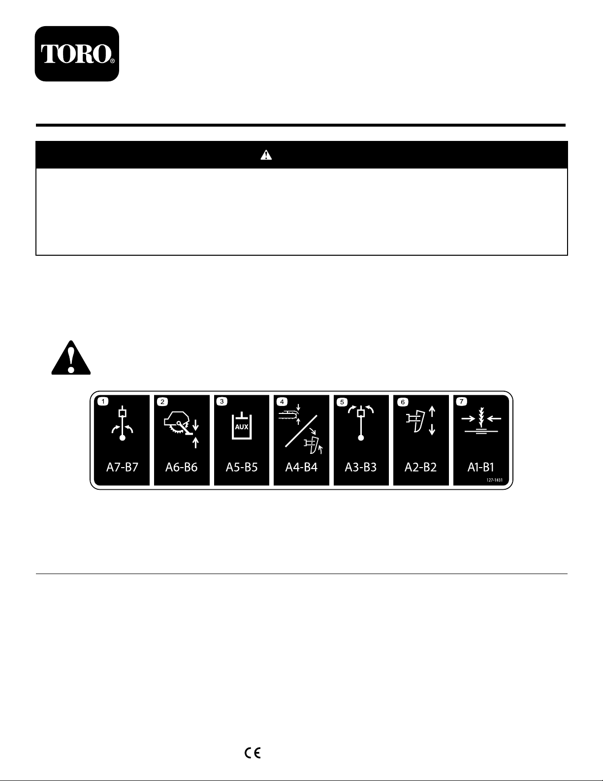
SafetyandInstructionalDecals
Safetydecalsandinstructionsareeasilyvisibletotheoperatorandarelocatednearanyareaofpotential
danger.Replaceanydecalthatisdamagedorlost.
127-1831
1.Plowswing5.Plow-headtilt
2.Rocksawstabilizerheight6.Plowheight
3.Auxiliaryfunction7.Sideshift
4.Crumberheight/Plowattitude
©2014—TheToro®Company
8111LyndaleAvenueSouth
Bloomington,MN55420
Registeratwww.T oro.com.
OriginalInstructions(EN)
PrintedintheUSA
AllRightsReserved
*3378-102*A
Page 2
LooseParts
Usethechartbelowtoverifythatallpartshavebeenshipped.
ProcedureDescription
1
2
3
4
5
6
Nopartsrequired
Rear-attachmenthydraulicvalve1
Valve-mountplate1
Hex-headscrew(12x30mm)
Rear-attachmenthydraulicvalve1
Nopartsrequired
Nopartsrequired
1
RemovingtheRear-cover PlateandtheCoverPlate
Qty.
–
2
–
–
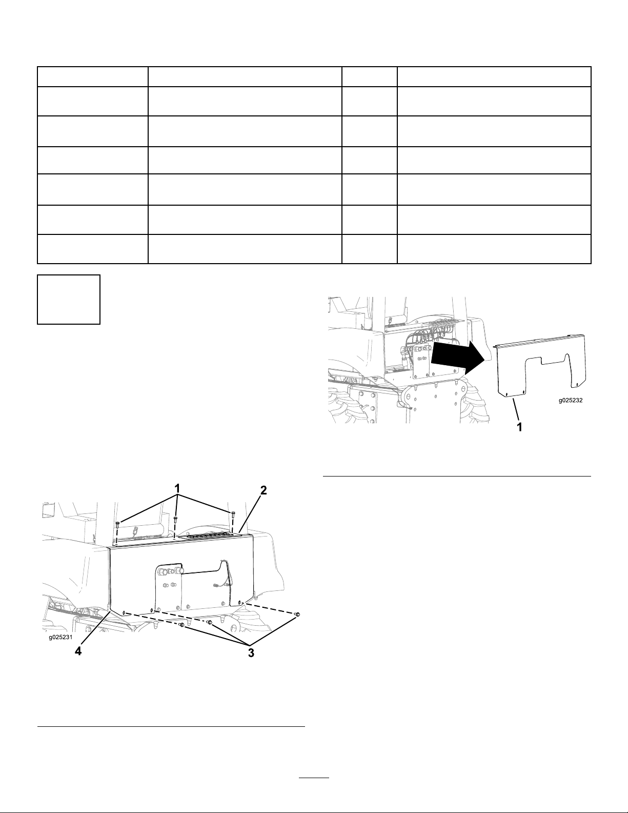
2.Removetherear-coverplate(Figure2).
Removetherear-coverplate.
Connectthehydrauliclinestothe
hydraulicttings.
Installthevalve-mountplate.
Connectthewiring-harnessconnectors
tothecoils.
Understandthehydraulicconnections.
Installtherear-coverplate.
Use
NoPartsRequired
Procedure
1.Removethe3hex-headscrews(10x30mm)from
thebulkheadandthe3hex-headscrews(12x30mm)
fromtherear-coverplate(Figure1).
Figure1
1.Hex-headscrews(10x30
mm)
2.Bulkhead4.Rear-coverplate
3.Hex-headscrews(12x30
mm)
Figure2
1.Rear-coverplate
3.Removethe2hex-headscrews(12x50mm)andthe
2locknuts(12mm)securingthecoverplatetothe
frame-mountplate(Figure3).
Note:Retainthe2locknuts(12mm).
2
Page 3
2
ConnectingtheHydraulic LinestotheHydraulicFittings
Partsneededforthisprocedure:
1Rear-attachmenthydraulicvalve
Figure3
1.Frame-mountplate
2.Coverplate
4.Removethecoverplate(Figure4).
1.Coverplate
3.Hex-headscrews(12x50
Figure4
Procedure
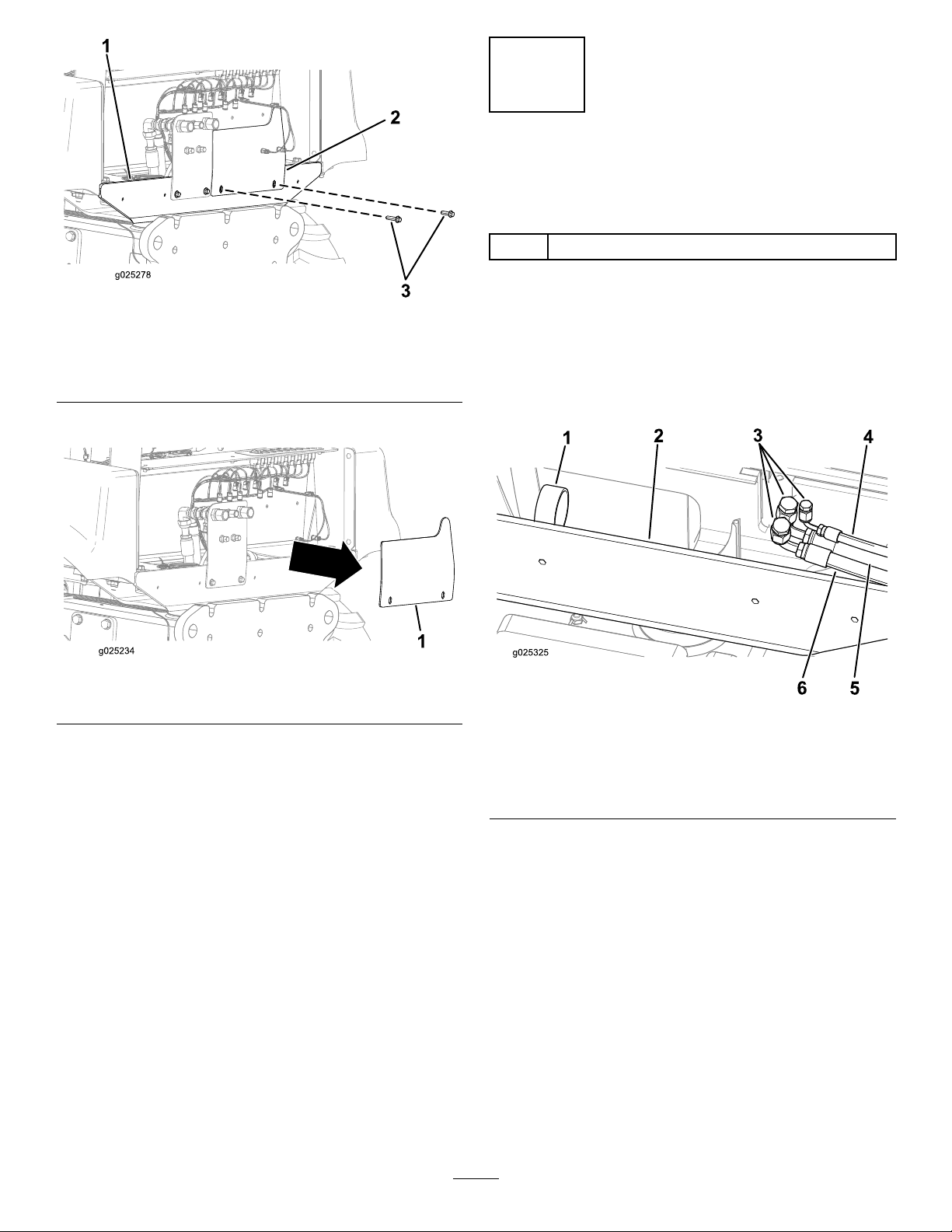
1.Removethe3hydrauliclines(pressure,return,andload
mm)
sense)fromtheclamp(behindtheframe-mountplate),
andmovethelinestotheright,towardtheproximityof
thehydraulicttingsontherear-attachmenthydraulic
Figure5).
valve(
Figure5
1.Clamp
2.Frame-mountplate5.Hydraulicpressureline
3.Plugsforthehydraulic
lines
4.Hydraulicloadsenseline
6.Hydraulicreturnline
2.Removetheplugsfromthe3hydrauliclines(Figure5).
Note:Checkthehydrauliclinesforanyleaks,butdo
nottouchthehydraulicuidwithyourhandsifaleak
exists.
3.Connectthehydraulic-pressurelinetothe
hydraulic-pressuretting(labeledPonthe
rear-attachmenthydraulicvalve)asshowninFigure6.
3
Page 4

1.Hydraulic-returntting
(labeledTonthe
rear-attachmenthydraulic
valve)
2.Hydraulicload-sense
tting(labeledLSonthe
rear-attachmenthydraulic
valve)
3.Hydraulic-pressure
tting(labeledPonthe
rear-attachmenthydraulic
valve)
Figure6
4.Hydraulic-pressureline
5.Hydraulicload-senseline
6.Hydraulic-returnline
3
InstallingtheValve-mount Plate
Partsneededforthisprocedure:
1Valve-mountplate
2
Hex-headscrew(12x30mm)
Procedure
1.Alignthe2holesintheframe-mountplatewiththe2
holesinthevalve-mountplate(Figure7).
2.Installthe2newhex-headscrews(12x30mm)and
the2locknuts(12mm)removedinstep
theRear-coverPlateandtheCoverPlateasshownin
Figure7.
3ofRemoving
4.Connectthehydraulicload-senselinetothehydraulic
load-sensetting(labeledLSontherear-attachment
hydraulicvalve)asshowninFigure6.
5.Connectthehydraulic-returnlinetothehydraulic-return
tting(labeledTontherear-attachmenthydraulic
valve)asshowninFigure6.
6.Installthevalve-mountplate;refertoInstallingthe
Valve-mountPlate.
Figure7
1.Valve-mountplate3.Frame-mountplate
2.Hex-headscrews(12x30
mm)
4
Page 5

4
Connectingthe Wiring-harnessConnectorsto theCoils
Partsneededforthisprocedure:
1Rear-attachmenthydraulicvalve
Procedure
Seethefollowinggureforconnectingthewiring-harness
connectorsintothefrontandbackofthecoilsonthe
rear-attachmenthydraulicvalve.
Note:Tomakesurethatthereisasolidconnection,ensure
thatthewiring-harnessconnectorsaresecurelyinsertedinto
theirrespectivecoilsontherear-attachmenthydraulicvalve.
Thewiring-harnessconnectorcorrespondtothecoilsonthe
rear-attachmenthydraulicvalveasshowninFigure8(from
lefttoright):
Figure8
1.Plowswingright
2.Reelcarrier
3.Plowsteerright
4.Plowup/plowdown9.Plowswingleft
5.Slidingoffset
6.Plow-boomoat
7.Plowsteerleft
8.Plow-swingoat
•Plowswingright
•Reelcarrier
•Plowsteerright
•Plowup/plowdown
•Slidingoffset
•Plow-boomoat
•Plowsteerleft
•Plow-swingoat
•Plowswingleft
5
Page 6

5
6
UnderstandingtheHydraulic Connections
NoPartsRequired
Procedure
Thehydraulicconnectionscorrespondtothenumbersonthe
rear-attachmenthydraulicvalveasfollows:
•A1-B1—Sideshift(Figure9)
•A2-B2—Plowheight(Figure9)
•A3-B3—Plow-headtilt(Figure9)
•A4-B4—Crumberheight/Plowaltitude(Figure9)
•A5-B5—Auxiliaryfunction(
•A6-B6—Rocksawstabilizerheight(Figure9)
•A7-B7—Plowswing(Figure9)
Figure9)
InstallingtheRear-coverPlate
NoPartsRequired
Procedure
1.Alignthe3holesontherear-coverplatewiththe
correspondingholesontheframe-mountplate(Figure
10).
Figure9
1.A5-B5(auxiliaryfunction)5.A4-B4(crumber
height/plowaltitude)
2.A3-B3(plow-headtilt)6.A6-B6(rocksawstabilizer
height)
3.A2-B2(plowheight)7.A7-B7(plowswing)
4.A1-B1(sideshift)
Figure10
1.Hex-headscrews(10x30
mm)
2.Bulkhead5.Frame-mountplate
3.Rear-coverplate
2.Installtherear-coverplateontotheframe-mountplate
withthe3hex-headscrews(12x30mm)removedin
step1ofRemovingtheRear-coverPlateandtheCover
Plate(Figure10).
3.Installthebulkheadwiththe3hex-headscrews(10x
30mm)removedinstep1ofRemovingtheRear-cover
PlateandtheCoverPlate(Figure10).
4.Hex-headscrews(12x30
mm)
6
Page 7

Notes:
7
Page 8

 Loading...