

Page 1

SlidingAttachmentKit
RT1200Trencher
ModelNo.25454—SerialNo.314000001andUp
ModelNo.25454E—SerialNo.314000001andUp
LooseParts
Usethechartbelowtoverifythatallpartshavebeenshipped.
FormNo.3377-984RevA
InstallationInstructions
Description
Slidemount
Pivotpin1
Boomcylinderpin1
Threadedrod2
HexNut4
FlatWasher(5/8inch)
Retainingring2
Screw(3/8inch)
Washer(3/8inch)
Nut(3/8inch)
Slideplate
Wearstrip2
Upperslideplate1
Idlerwheel2
Bearing2
Chainassembly
Rolleraxle2
Squareholewasher
Washer(21/2inch)
Washer(5/8inch)
Hexbolt(5/8x13/4inch)
Hexbolt(5/8x23/4inch)
Hydrauliccylinderboom1
Nopartsrequired
SideShift
Bolt6
Washer6
Nut6
Hydraulicline2
Qty.
10
12
Use
1
1
1
1
1
Assemblethekit
2
3
4
3
1
–
1
Preparethemachine.
Installthemountingframe.
Note:Additionalhydrauliccomponentsarerequiredforthe
operationofthiskit.PleaseseeyourAuthorizedToroDealer
foradditionalinformation.
©2014—TheT oro®Company
8111LyndaleAvenueSouth
Bloomington,MN55420
Registeratwww.T oro.com.
OriginalInstructions(EN)
PrintedintheUSA
AllRightsReserved
*3377-984*A
Page 2

WARNING
CALIFORNIA
Proposition65Warning
ThisproductcontainsachemicalorchemicalsknowntotheStateofCaliforniato
causecancer,birthdefects,orreproductiveharm.
2
Page 3
AssemblingtheSliding
1
2
3
1
g025743
1
5
2
6
7
8
4
2
g025744
3
4
AttachmentKit
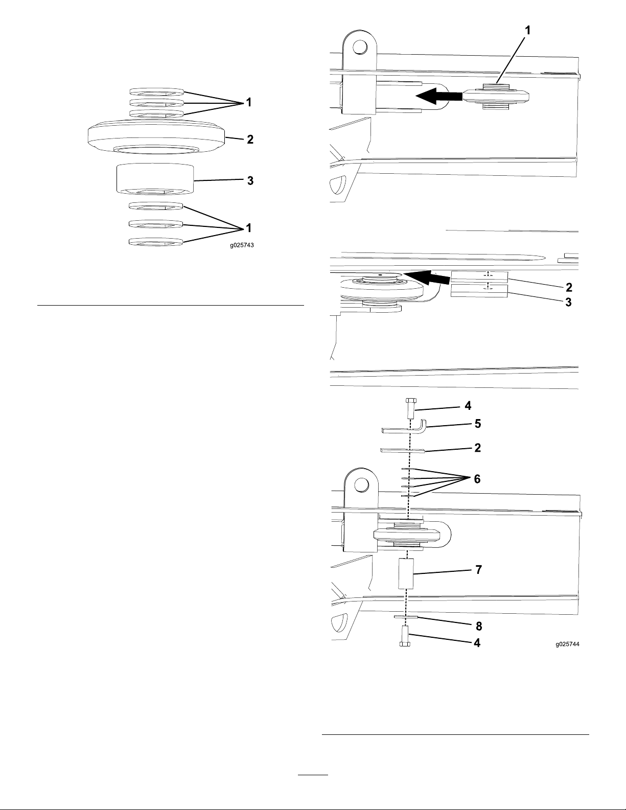
1.Stacktheboomidlerwheelassembly(Figure1).
Figure1
1.Square-holewasher
2.Idlerwheel
3.Bearing
2.Slidetheboom-idlerwheelintotheslidmount
assembly,andinserttheslideplateandwearstrip
(Figure2).
Figure2
1.Boomidlerwheel5.Wearstrip
2.Wearstrip6.Washer
3.Slideplate
4.Hexbolt(5/8x13/4inch)8.Washer(21/2inch)
7.Rolleraxle
3
Page 4

3.Slidethe-side-boomidlerwheelintothemount
1
g025745
1
2
3
4
2
1
g025746
1
2
2
1
3
g025747
assembly(Figure3).
Figure3
1.Side-boom-idlerwheel
4.Installtherolleraxletosecuretherollerintoplace
Figure4).
(
Note:Slidetheboomsothatyoucaninstallthetop
bolt.
Figure4
1.Hexbolt(5/8x13/4inch)
2.Washer(21/2inch)
3.Right-boom-idlerwheel
4.Rolleraxle
5.Installthethreadedrodstotheattachment(Figure5).
1.Hexnut
2.Threadedrod
4
Figure5
3.Attachmentframe
Page 5

6.Installthechainstotheframeoftheattachment
1
2
3
3
4
2
5 5
2
g025748
1
3
2
g025749
1 2
3
4
1
2
3
4
g025750
1
2
3
4
1
g025751
(Figure6).
8.Attachthechainassemblytothethreadedrods(Figure
8).
Figure8
1.Chainassembly3.Chainretainingpin
2.Chainpin
4.Threadedrod
9.Installthepistonmountingttingendofthehydraulic
cylindertotheattachmentframe(Figure9).
Figure6
1.Flatwasher(5/8inch)4.Attachmentframe
2.Chainpin5.Chain-retainingpin
3.Chainassembly
7.Routethechainassemblyaroundtheidlerwheelto
thethreadedrod(Figure7).
Figure7
1.Chainassembly
2.Threadedrod
3.Idlerwheel
1.Retainingpin
2.Pivotpin
Figure9
3.Pistonmountingtting
4.Attachmentframe
5
Page 6

10.Installthecylindermountingttingendofthehydraulic
1
2
1
2
3
4
5
6
g025752
cylindertotheattachmentframe(Figure10).
Figure10
1.Cylinder-mountingtting4.Washer(3/8inch)
2.Attachmentframe
3.Nut(3/8inch)6.Screw(3/8inch)
5.Boomcylinderpin
6
Page 7

PreparingtheMachine
3
1
2
2
g025682
4
1
2
3
g025683
g025686
1
2
1
2
1.Movethemachinetoalevelsurface.
2.Settheparkingbrakeandlowertheattachmentsto
theground
3.Stoptheengineandremovethekey .
4.Ifarear-mountedattachmentsuchasthebackhoeis
installedonthemachine,removetheattachment;refer
totheOperator’ sManualfortheattachment.
InstallingtheMountingFrame
Note:Yourliftingequipmentmusthavealiftcapacityof
136kg(300lb).
Note:Removeallexistingattachmentsandboltsfromthe
mountingframepriortoinstallationofthekit.
Note:Savebolts,washers,andnutstoattachthekit.
Figure12
Bottombolts
1.Nut3.Bolt
2.Washer
1.Applymedium-grade(serviceremovable)
thread-lockingcompoundtothethreadsofthebolts.
2.Placethe6boltsandwashersonthemachinesothey
stickoutofthemountingframe(Figure11andFigure
12).
Figure11
Topbolts
3.Useliftingequipmenttoraiseorlowerthesliding
attachmentassemblyuntiltheholesinthemounting
framealignwiththeholesonthemachine(Figure11
andFigure12).
4.Torquetheboltsto1220to1491N-m(900to1100
ft-lb).
5.Removetheliftingequipmentfromthemounting
frame.
6.Installthehydrauliclinestothemachine(
Note:Additionalhydrauliccomponentsarerequired
fortheoperationofthiskit.PleaseseeyourAuthorized
ToroDealerforadditionalinformation.
Figure13).
1.Nut3.Bolt
2.Washer
1.Lefthydraulicline(A1)2.Righthydraulicline(B1)
Figure13
Note:Installnewattachmentstothefrontofthemounting
faceoftheslidingattachmentkitasyouwouldtothefront
ofthemachine’smountingface.Longerhydrauliclineswill
beneeded.ContactyourAuthorizedToroDealerformore
information.
7
Page 8

 Loading...