

Page 1

FormNo.3397-318RevA
CenterTrencher
RT1200TractionUnit
ModelNo.25453—SerialNo.314000001andUp
ModelNo.25453E—SerialNo.314000001andUp
Registeratwww.T oro.com.
OriginalInstructions(EN)
*3397-318*A
Page 2
WARNING
CALIFORNIA
Proposition65Warning
Thisproductcontainsachemicalorchemicals
knowntotheStateofCaliforniatocausecancer,
birthdefects,orreproductiveharm.
Introduction
Thisattachmentisdesignedtodigtrenchesinsoiltobury
cablingandpipingforvariousapplications.Itisnotintended
tocutrock,wood,oranyothermaterialotherthansoil.
Readthisinformationcarefullytolearnhowtooperateand
maintainyourproductproperlyandtoavoidinjuryand
productdamage.Youareresponsibleforoperatingthe
productproperlyandsafely.
YoumaycontactTorodirectlyatwww .Toro.comforproduct
andaccessoryinformation,helpndingadealer,ortoregister
yourproduct.
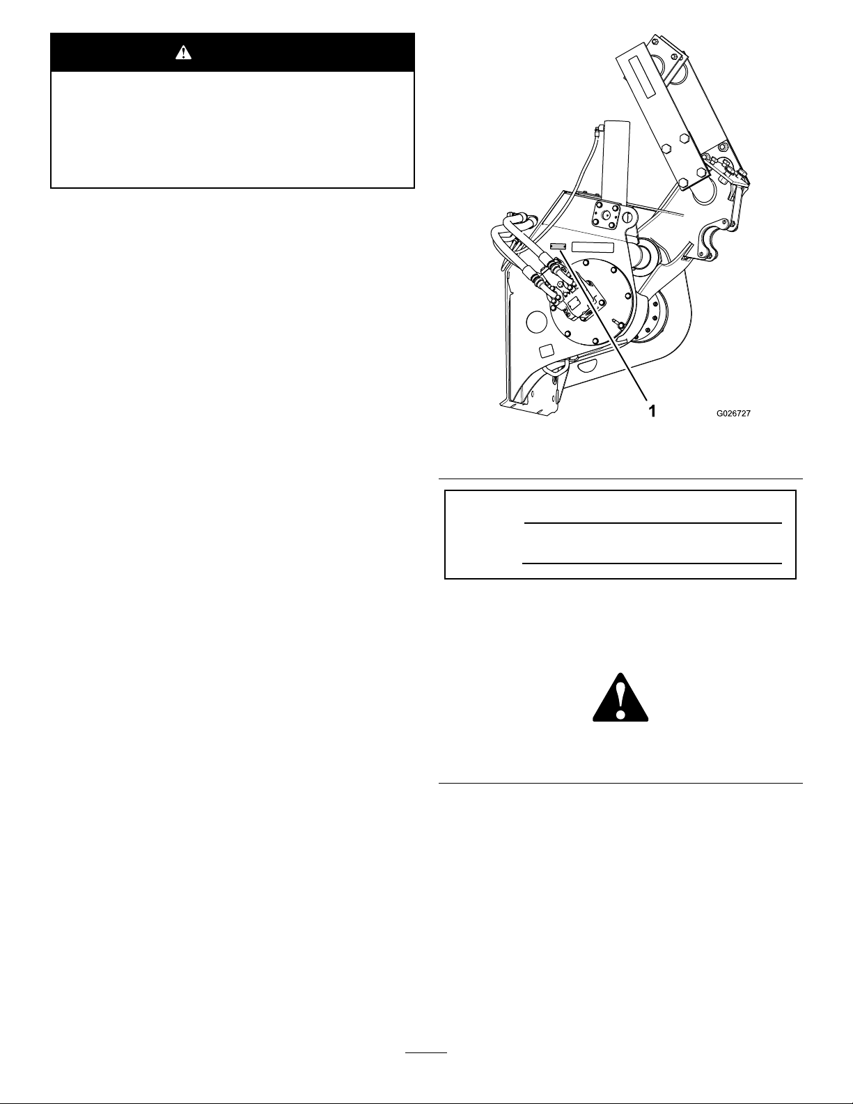
Figure1
1.Locationofthemodelandserialnumberplate
Wheneveryouneedservice,genuineT oroparts,oradditional
information,contactanAuthorizedToroServiceDealer
orToroCustomerServiceandhavethemodelandserial
numbersofyourproductready.Figure1illustratesthe
locationofthemodelandserialnumbersontheproduct.
Writethenumbersinthespaceprovided.
ModelNo.
SerialNo.
Thismanualidentiespotentialhazardsandhassafety
messagesidentiedbythesafety-alertsymbol(Figure2),
whichsignalsahazardthatmaycauseseriousinjuryordeath
ifyoudonotfollowtherecommendedprecautions.
Figure2
1.Safety-alertsymbol
Thismanualuses2wordstohighlightinformation.
Importantcallsattentiontospecialmechanicalinformation
andNoteemphasizesgeneralinformationworthyofspecial
attention.
©2015—TheToro®Company
8111LyndaleAvenueSouth
Bloomington,MN55420
Contactusatwww.Toro.com.
2
PrintedintheUSA
AllRightsReserved
Page 3

Contents
Safety
Safety...........................................................................3
SafetyandInstructionalDecals.................................4
Setup............................................................................5
1PreparingtoInstalltheTrencher.............................6
2InstallingtheSpeed-ShiftSwitch.............................6
3InstallingtheTrencherAttachment..........................8
4PreparingtheHydraulicMotor...............................11
5ConnectingtheLiftCylinderHoses........................12
6InstallingtheHydraulicHoses...............................13
7ConnectingtheWireHarnesstotheHydraulic
Motor...............................................................14
8PurgingAirfromtheHydraulicMotorandLift
Cylinder.............................................................15
9InstallingtheSprocket..........................................15
10InstallingtheAuger............................................16
11InstallingtheBoom............................................18
12AligningtheBoom.............................................19
13InstallingtheDiggingChain.................................21
14InstallingtheRestraintBar...................................21
Operation....................................................................22
SelectingtheProperComponentsfortheRock
Boom................................................................22
UsingtheTrencher.................................................24
OperatingTips......................................................27
Maintenance.................................................................28
GreasingtheTrencher.............................................28
GreasingtheRockBoom.........................................28
ServicingthePlanetaryDrive...................................29
ServicingtheTrencherDiggingChain.......................30
ReplacingtheDiggingChain....................................34
Storage........................................................................37
Troubleshooting...........................................................38
Improperlyusingormaintainingthisattachmentcan
resultininjury.Toreducethepotentialforinjury,
complywiththesesafetyinstructionsandthoseinthe
tractionunit
thesafetyalertsymbol,whichmeansCaution,Warning,
orDanger—personalsafetyinstruction.Failureto
complywiththeinstructionmayresultinpersonalinjury
ordeath.
Operator’ s Man ual
.Alwayspayattentionto
WARNING
Whentheengineisoff,attachmentsintheraised
positioncangraduallylower.Someonebelow
theattachmentmaybepinnedorinjuredbythe
attachmentasitlowers.
Alwayslowertheattachmenteachtimeyoushut
offthetractionunit.
WARNING
Lightningcancausesevereinjuryordeath.
Iflightningisseenorthunderisheardinthearea,
donotoperatethemachine;seekshelter.
CAUTION
Hydraulicttings,hydrauliclines/valves,and
hydraulicuidmaybehotandcanburnyouifyou
touchthem.
•Weargloveswhenmaintaininghydraulic
components.
•Allowthetractionunitandtrenchertocool
beforetouchinghydrauliccomponents.
•Donottouchhydraulicuidspills.
DANGER
Themovingteethandaugerwillcutorseveryour
hands,feet,orotherbodyparts.
•Keephands,feet,andanyotherpartofyour
bodyorclothingawayfrommovingteeth,auger,
orotherparts.
•Beforeadjusting,cleaning,repairing,or
inspectingthetrencher,lowerthetrencherto
theground,stoptheengine,waitforallmoving
partstostop,andremovethekey.
3
Page 4
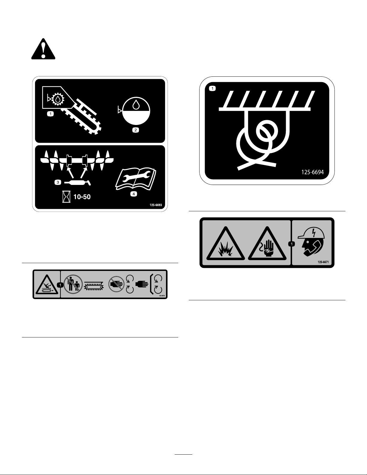
SafetyandInstructionalDecals
Safetydecalsandinstructionsareeasilyvisibletotheoperatorandarelocatednearanyareaofpotential
danger.Replaceanydecalthatisdamagedorlost.
125–6694
125-6693
1.Trencheroil3.Lubricatetheaugerevery
10to50operatinghours.
2.Gear-boxoil4.ReadtheOperator’s
Manualformaintenance
information.
125–6670
1.Cutting/dismembermenthazard,trencher—keep
bystandersawayfromthetrencher;keepawayfrommoving
parts;keepallguardsandsafetiesinplace.
1.Tie-downpoint
125-6671
1.Explosionhazard;electricshockhazard—calllocalutilities
beforedigging.
4
Page 5

Setup
LooseParts
Usethechartbelowtoverifythatallpartshavebeenshipped.
ProcedureDescription
1
2
3
4
5
6
7
Nopartsrequired
Speed-shiftswitch
Trencherattachment1
Bolt(1x5-1/2inch)
Flatwasher(1inch)
Locknut(1inch)
45°elbowtting(3/4inch)
90°anged-elbowtting(1inch)
O-ring
Flangeclamp4
Hex-headbolt(12x45mm)
Lockwasher(12mm)
45°elbowtting(3/8inch)
Hose(34-1/2inch)
Hose(40-1/2inch)
Hose(47inch)
Cabletie
Cabletie
Qty.
Use
–
1
5
7
6
1
2
2
8
8
2
1
1
1
1
1
Preparetoinstallthetrencher.
Installthespeed-shiftswitch.
Installthetrencher.
Preparethehydraulicmotor.
Connecttheliftcylinderhoses.
Installthehydraulichoses.
Connectthewireharnesstothe
hydraulicmotor.
8
9
10
11
Nopartsrequired
Sprocketsegment
Bolt(9/16x2-3/4inch)
Locknut(9/16inch)
Leftauger
Rightauger1
Augershaft
Augersprocket1
Bearing2
Key(1/2x5inch)
Hex-headbolt(3/4x4inch)
Locknut(3/4inch)
Hex-headbolt(5/8x2-1/2inch)
Locknut(5/8inch)
Nopartsrequired
–
2
8
8
1
1
1
2
2
4
4
–
Purgeairfromthehydraulicmotorand
liftcylinder.
Installthesprocket.
Installtheauger.
Installtheboom.
5
Page 6
ProcedureDescription
12
13
Boom1
Hex-headbolt(3/4x2-1/2inch)
Washer(3/4inch)
Locknut(3/4inch)
Hex-headbolt(1x2-1/2inch)
Washer(1inch)
Locknut(1inch)
Shim
Diggingchain1
Masterpin1
Safetypin
Qty.
Use
4
4
4
2
4
2
3
1
Installtheboom.
Installthediggingchain.
14
Restraintbar1Installtherestraintbar.
1
PreparingtoInstallthe Trencher
NoPartsRequired
Procedure
1.Movethemachinetoalevelsurfacethatisbelowthe
liftingequipment.
2.Ifthebackhoeisinstalledonthemachine,lowerthe
boomuntilthebucketisontheground.
3.Ensurethatthetiltfeatureofthemachineisleveland
thetilt-lockoutpinissecuretothechassis-lockout
bracket;refertotheOperator’sManualforthemachine.
2
InstallingtheSpeed-Shift Switch
Partsneededforthisprocedure:
1
Speed-shiftswitch
ConnectingtheSpeed-ShiftSwitch
1.Removethe6hex-angedbolts(12x30mm)that
securetherear-coverplatetotherearbulkheadofthe
machine,andremovethecoverplate(Figure3).
4.Shutoffthemachine,settheparkingbrake,and
removethekeyfromthekeyswitch.
Figure3
1.Bulkhead
2.Rear-coverplate
2.Removetheleftmostblankingplatefromthe
auxiliary-controlpanel(Figure4).
6
3.Hex-angedbolt(12x30
mm)
Page 7
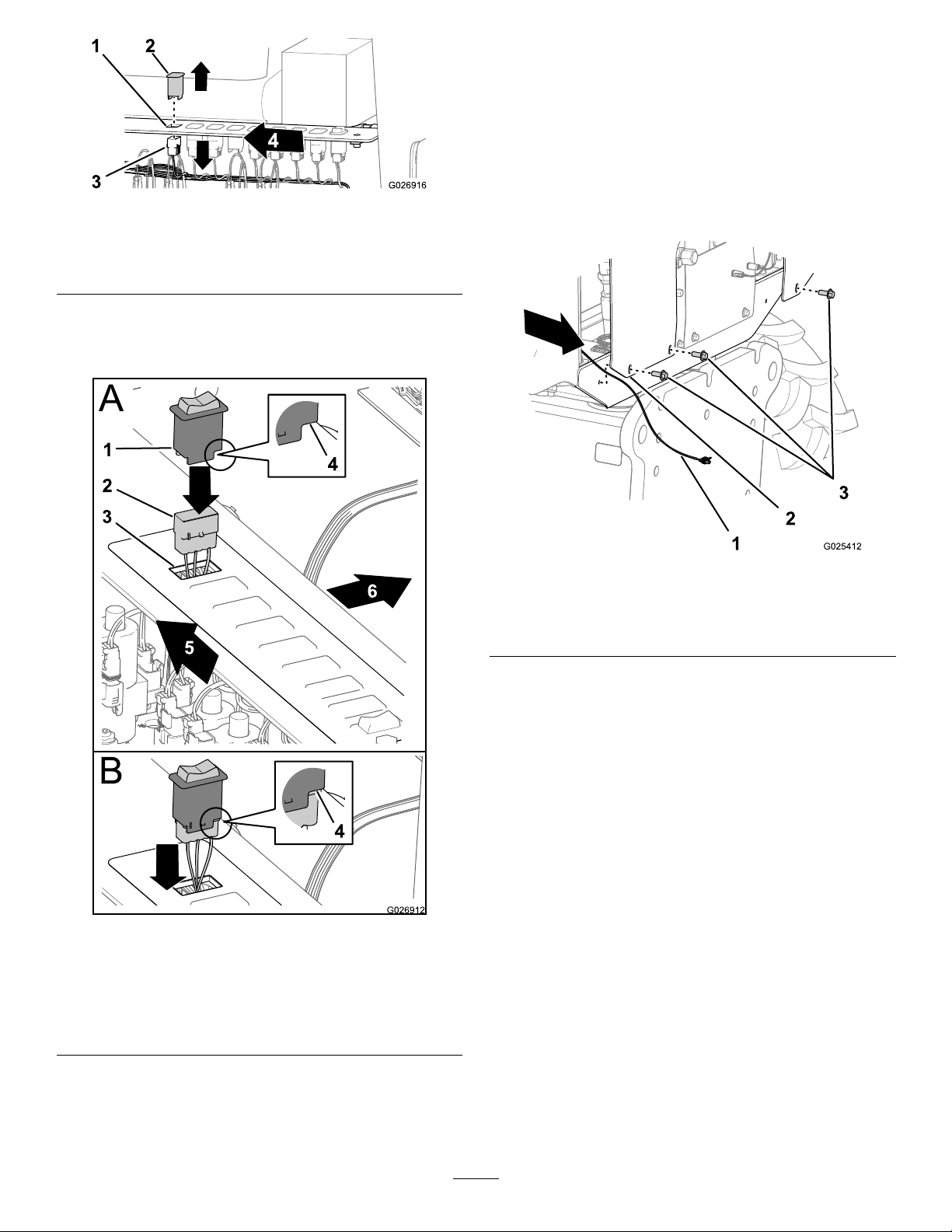
Figure4
1.Switchopening
(auxiliary-controlpanel)
2.Blankingplate
3.10-socketconnector
4.Left
3.Pullthe10-socketconnectoratthefarthestleftof
thewiringharnessofthemachinethroughtheswitch
openingwheretheblankingplugwaslocated(Figure5).
5.Alignthelargenotchinthebodyofthespeed-shift
switchsothatthenotchistowardthefrontofthe
machine,andsnaptheswitchintotheauxiliary-control
panel(Figure5).
RoutingtheSpeed-SwitchHarness
1.Locatetheharnesswiththe2-socketconnectorfor
thespeed-shiftsolenoidonthehydraulicmotorinthe
lowerleftcornerofthebulkheadinterior(Figure6).
Figure5
1.Speed-shiftswitch4.Largenotch(speed-switch
2.10-socketconnector
3.Switchopening
(auxiliary-controlpanel)
5.Leftsideofthemachine
6.Frontofthemachine
Figure6
1.Harness(speed-shift
solenoid)
2.Rear-coverplate
3.Hex-angedbolts(12x30
mm)
2.Removethecabletiethatsecuresthespeed-shiftwiring
leadtotheharnessofthemachine.
3.Routetheharnessrearward,betweentheleftrear
fenderandtherear-coverplateasshowninFigure6.
4.Aligntherear-coverplatetotherearbulkheadofthe
machine(Figure3).
5.Securethecoverplatetothebulkheadwiththe6
hex-angedbolts(12x30mm)thatyouremovedin
step1.
body)
4.Connectthe10-socketconnectorofthewiringharness
tothe10-pinconnectorofthespeed-shiftswitch
(Figure5).
7
Page 8
3
InstallingtheTrencher Attachment
Partsneededforthisprocedure:
1Trencherattachment
5
Bolt(1x5-1/2inch)
7
Flatwasher(1inch)
6
Locknut(1inch)
Procedure
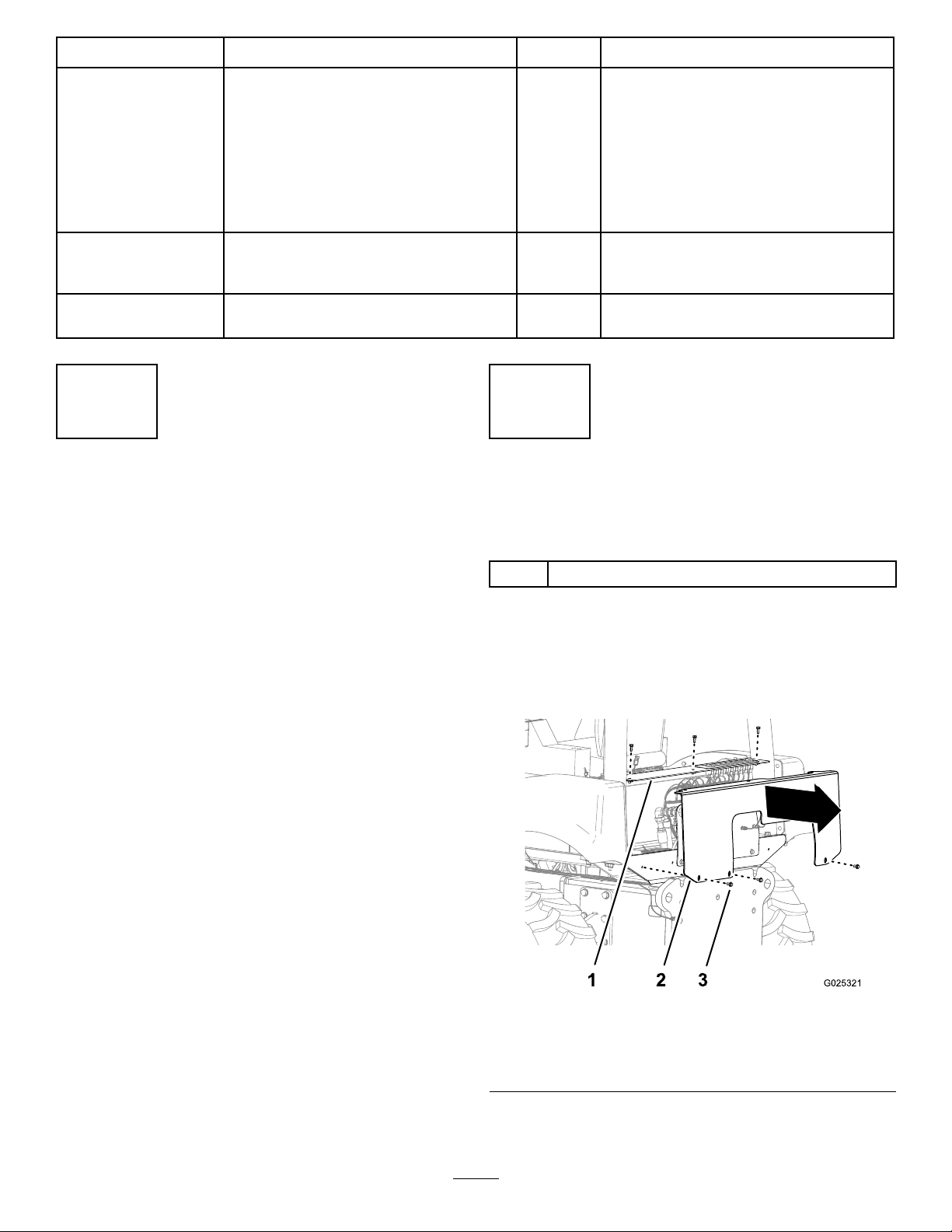
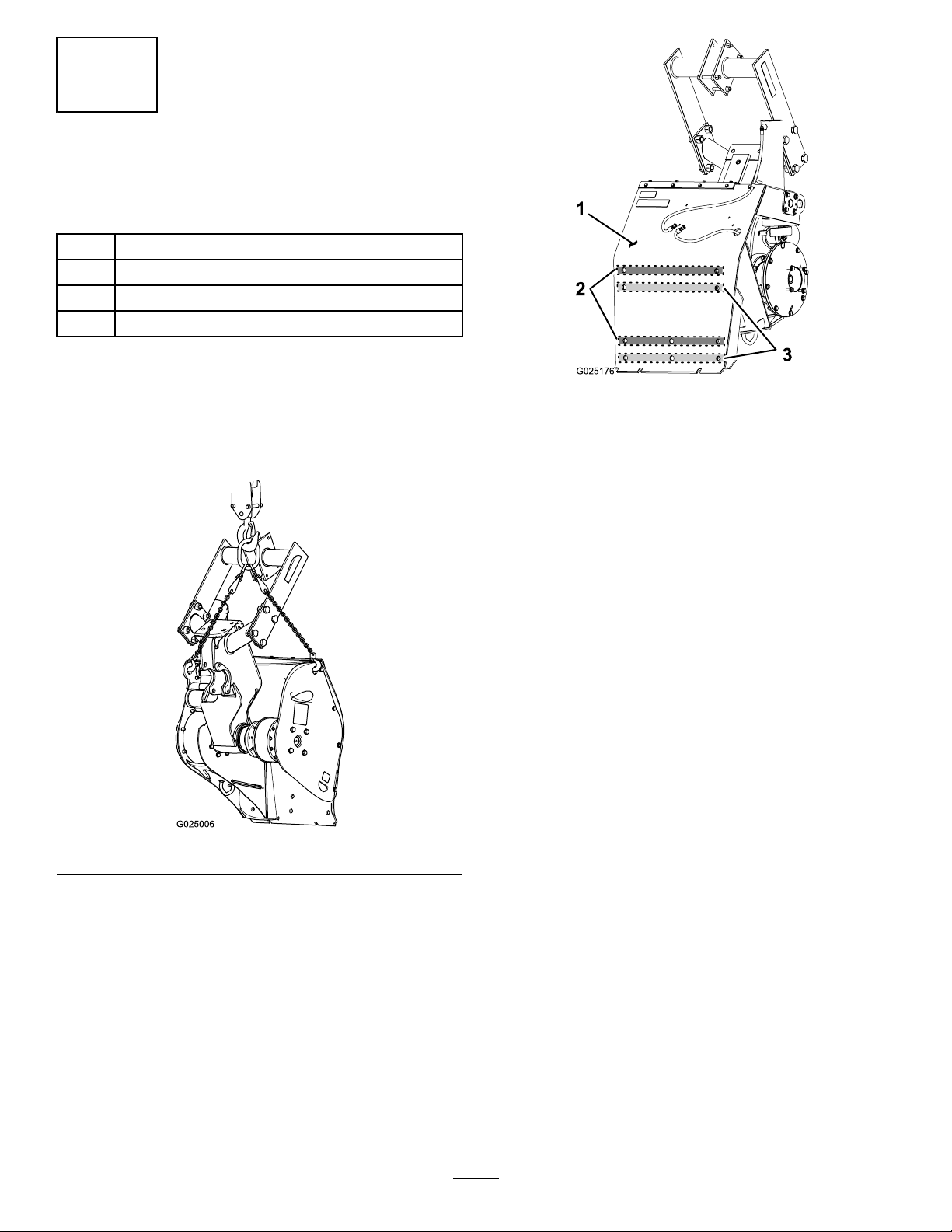
1.RaisetheattachmentofftheoorasshowninFigure7.
Important:Ensurethattheliftingequipmenthas
aliftingcapacityofatleast405kg(893lb).
Figure8
1.Mountingplate
2.Holes(rows1and3for
machineswithatrack
drive)
Note:Ifyourmachinehasatrackdrive,usetheholes
inrows1and3;refertoitem2inFigure8.
Ifyourmachinehaswheels,usetheholesinrows2
and4;refertoitem3inFigure8.
3.Insertalocknutintothenutretainerlocatedinsidethe
trencherattheholeinrow1(machineswithatrack
drive)orrow2(machineswithwheels)asshownin
Figure9.
3.Holes(rows2and4for
machineswithwheels)
Figure7
2.Locatethe2rowsofholesinthemountingplatethat
youwillusetosecuretheattachmenttothetraction
unit(Figure8).
8
Page 9
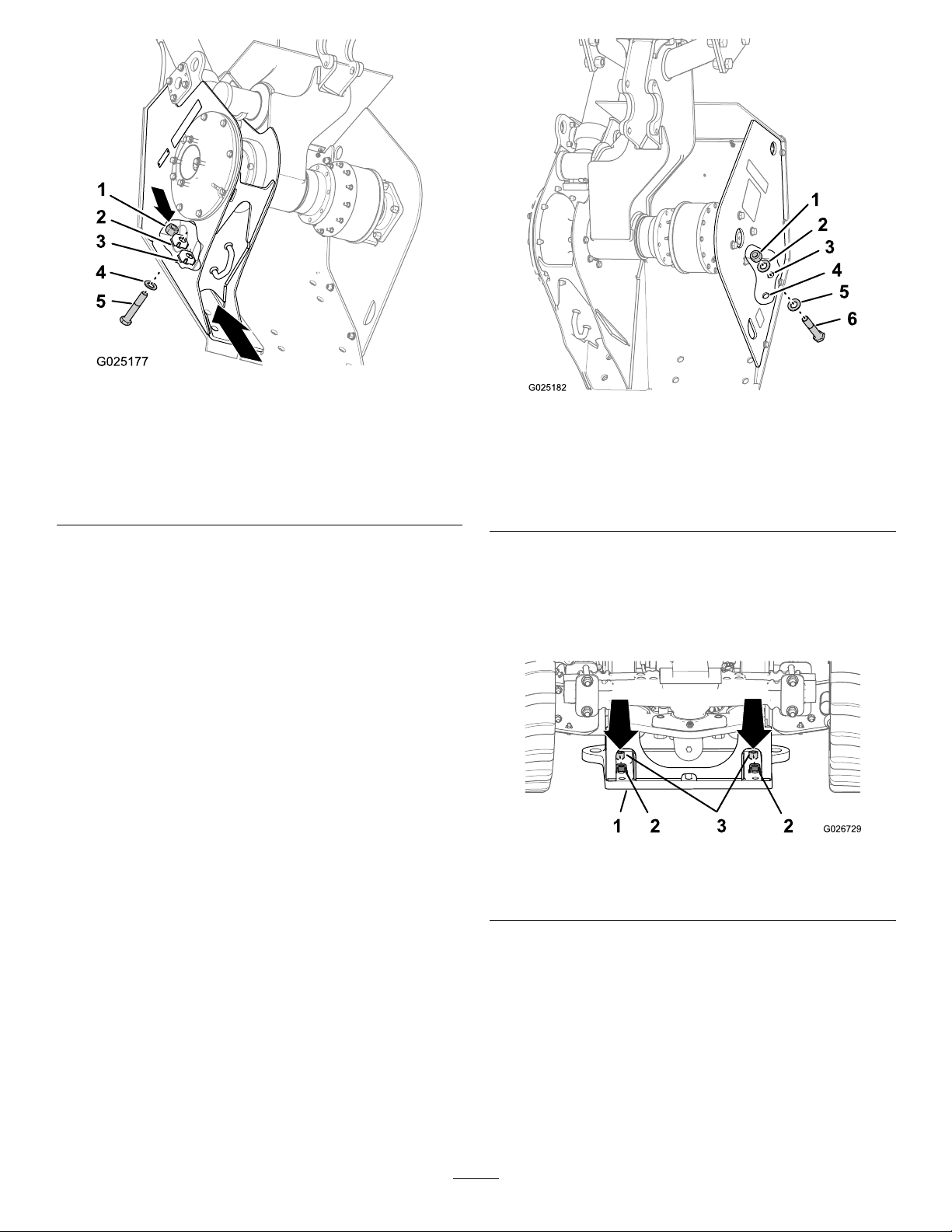
1.Locknut(1inch)
2.Upper-nutretainer
(machineswithatrack
drive)
3.Lower-nutretainer
(machineswithwheels)
Figure9
4.Washer
5.Bolt(1x5-1/2inch)
Figure10
1.Locknut(1inch)4.Hole(row2formachines
2.Washer5.Washer
3.Hole(row1formachines
withatrackdrive)
withwheels)
6.Bolt(1x5-1/2inch)
4.Slipawasherontoabolt(1x5-1/2inch)andpartially
threadtheboltintothenutthatyouinstalledinstep
3;refertoFigure9.
5.Slipawasherontoeachoftheremainingbolts(1
x5-1/2inch),andinsertthemfromoutsideofthe
trencher(Figure10)throughtheremainingholeinrow
1(machineswithatrackdrive)orrow2(machines
withwheels).
6.Slipawasherandpartiallythreadalocknutontothe
endofeachofthebolts.
7.Insert2locknutsintothe2nutretainerslocatedatthe
forwardsideoftherear-attachmentmountingplateof
themachine(Figure11).
Figure11
1.Mountingplate
2.Nutretainer
3.Locknut(1inch)
8.Positionthetrenchersothatitisattherearofthe
tractionunit.
9.Aligntherowofboltsonthetrenchersothattheyare
abovetheupperslotsinthemountingplateonthe
tractionunit(Figure12).
9
Page 10
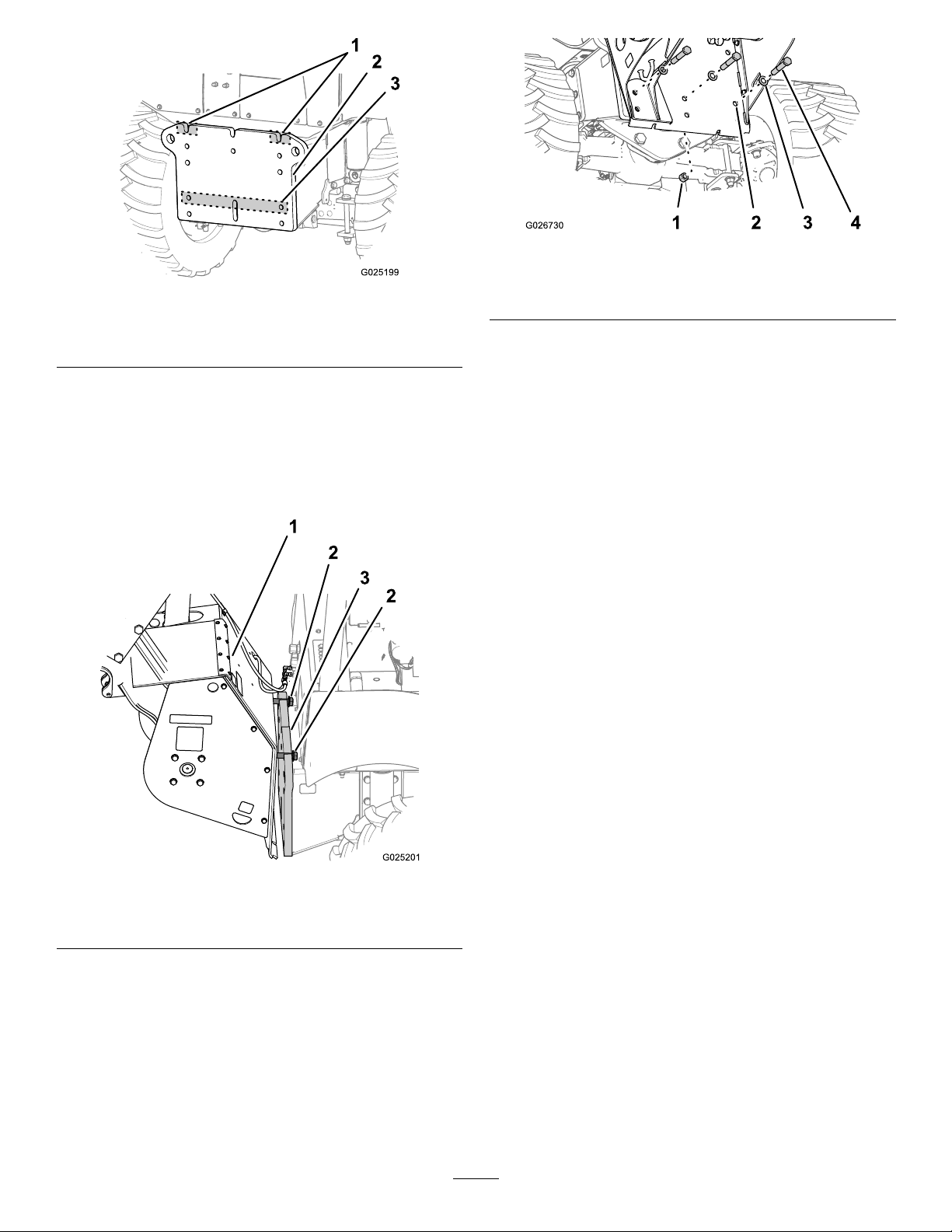
Figure14
Figure12
1.Upperslots3.Lowerholes
2.Mountingplate
10.Lowerthetrencherattachmentuntilitisalignedwith
themountingplateandtheboltstintheupperslots.
Note:Ensurethatthewashersontheboltsprojecting
throughthetrencherattachmentarealignedtothe
forwardsideofthemountingplateasyoulowerthe
trencherattachmentonthemachine;refertoFigure13.
1.Locknut(1inch)
2.Hole(trencherattachment)4.Bolt(1x5-1/2inch)
3.Washer
13.Attheforwardsideofthemountingplateforthe
machine,threadalocknutontothelower,centerbolt
(Figure14).
14.Torquetheboltsandthelocknutsto1341to1368N-m
(989to1009ft-lb).
Figure13
1.Trencher
2.Boltheadandwasher
3.Upperslot(2)
11.Handtightenalltheboltsandnuts.
12.Frominsidethetrencherattachment,installthe3bolts
(1x5-1/2inch)and3washersthroughtheholesin
row3(formachineswithatrackdrive)orthrough
theholesinrow4(formachinesformachineswith
wheels).RefertoFigure8)andFigure14.
10
Page 11
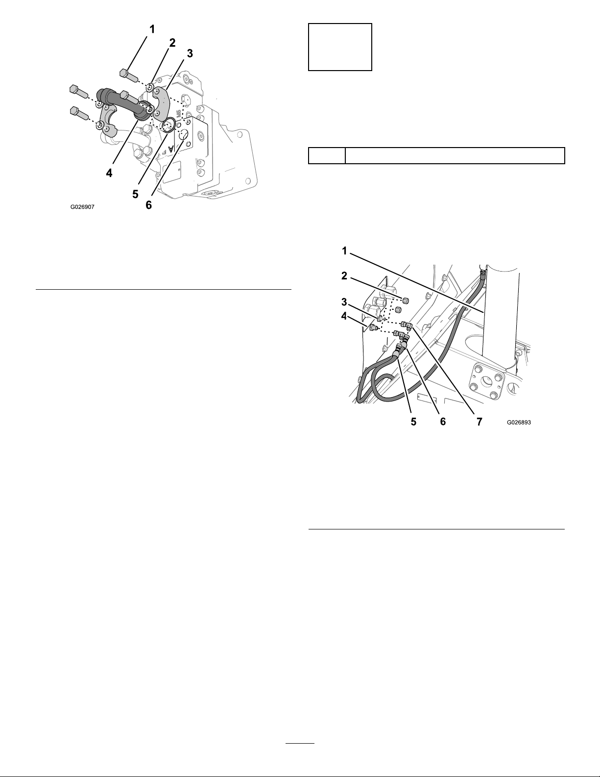
4
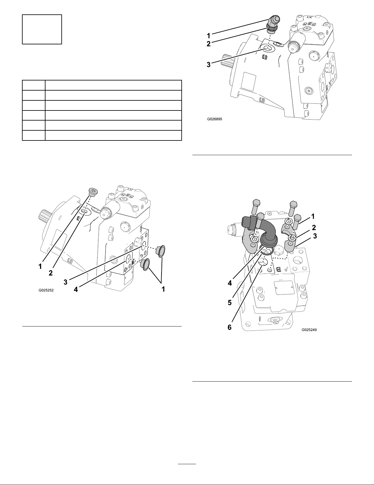
PreparingtheHydraulicMotor
Partsneededforthisprocedure:
1
45°elbowtting(3/4inch)
2
90°anged-elbowtting(1inch)
2
O-ring
4Flangeclamp
8
Hex-headbolt(12x45mm)
8
Lockwasher(12mm)
Procedure
1.RemoveanddiscardtheplugsfromtheportsA,B,and
L1ofthehydraulicmotorasshowninFigure15.
Figure16
1.45°elbowtting(3/4inch)
2.Jamnut
3.PortL1
3.PlacetheO-ringsintothegroovesintheangesofthe
90°anged-elbowttings.
4.AlignaangedelbowandO-ringoverportBofthe
hydraulicmotor(Figure17).
Figure15
1.Plug3.PortA
2.PortL14.PortB
2.Installthe45°elbowtting(3/4inch)intoPortL1as
showninFigure16.
Note:Tightenthejamnutfortheelbowttingnger
tight.
Figure17
1.Hex-headbolt(12x45
mm)
2.Lockwasher(12mm)5.O-ring
3.Flangeclamp(2)
4.90°anged-elbowtting
6.PortB
5.Securetheangedelbowtothehydraulicmotorwith
2angeclamps,4hex-headbolts(12x45mm),and4
lockwashers(12mm)asshowninFigure17.
Note:Tightenthehex-headboltsngertight.
6.AlignaangedelbowandO-ringoverportAofthe
hydraulicmotor(Figure18).
11
Page 12
5
ConnectingtheLiftCylinder Hoses
Partsneededforthisprocedure:
2
45°elbowtting(3/8inch)
Procedure
Figure18
1.Hex-headbolt(12x45
mm)
2.Lockwasher(12mm)5.O-ring
3.Flangeclamp(2)
7.Securetheangedelbowtothehydraulicmotorwith
2angeclamps,4hex-headbolts(12x45mm),and4
lockwashers(12mm)asshowninFigure18.
Note:Tightenthehex-headboltsngertight.
4.90°anged-elbowtting
6.PortA
1.Removethe2caps(3/8inch)fromthebulkhead
ttingsfortheextendandretractcircuitsforthelift
cylinder(Figure19).
Figure19
1.Liftcylinder5.45°elbowtting(3/8inch)
2.Cap(3/8inch)
3.Bulkheadtting(extend
circuit)
4.Bulkheadtting(retract
circuit)
6.Extendhose
7.Retracthose
2.Installthe2elbowttings(45°)ontothebulkhead
ttingsngertight(Figure19).
3.Connecttheextendhosetothe45°elbowtting
connectedtothebulkheadttingfortheextend
hydrauliccircuit(Figure19).
4.Connecttheretracthosetothe45°elbowtting
connectedtothebulkheadttingfortheretract
hydrauliccircuit(Figure19).
5.Tightentheelbowstothebulkheadttingsandthe
hosetotheelbowsto20to28N-m(15to21lb-ft).
12
Page 13

6
InstallingtheHydraulicHoses
Partsneededforthisprocedure:
1
Hose(34-1/2inch)
1
Hose(40-1/2inch)
1
Hose(47inch)
1
Cabletie
Procedure
1.Removethe2caps(1inch)andthe1cap(5/8inch)
fromthebulkheadttingsinthehydraulic-attachment
panel(Figure20).
1.Bulkheadtting
(pressure-hydraulic
circuit—A)
2.Bulkheadtting(case
drain)
3.Bulkheadtting
(return-hydraulic
circuit—B)
4.Pressurehose(88cmor
34-1/2inch)
Figure21
5.Case-drainhose(1 19cm
or47inch)
6.Returnhose(103cmor
40-1/2inch)
7.Cabletie
Figure20
1.Bulkheadtting
(pressure-hydrauliccircuit)
2.Bulkheadtting(case
drain)
3.Bulkheadtting
(return-hydrauliccircuit)
4.Hydraulic-attachment
panel
5.Caps
2.Installthepressurehose(88cmor34-1/2inch);
case-drainhose(119cmor47inch);andreturnhose
(103cmor40-1/2inch)betweenthettingsonthe
hydraulic-attachmentpanel(Figure21)andthettings
thatyouinstalledonthehydraulicmotorasshownin
Figure22.
Note:Ensurethattheangledttingonthepressure
hoseisconnectedtothebulkheadttingforthe
pressure-hydrauliccircuit.Alsoensurethattheangled
ttingonthereturnhoseisconnectedtothebulkhead
ttingforthereturn-hydrauliccircuitatthehydraulic
attachmentpanel.
Figure22
1.45°elbowtting(3/4inch,
casedrain)
2.90°anged-elbowtting(
pressure-hydrauliccircuit)
3.90°anged-elbowtting
(return-hydrauliccircuit)
4.Pressurehose(88cmor
34-1/2inch)
5.Case-drainhose(1 19cm
or47inch)
6.Returnhose(103cmor
40-1/2inch)
3.Securethe3hydraulichoseswithacabletie(Figure21).
4.Torquethehydraulicttingsandhoses;refertothe
tablebelow:
13
Page 14

Component
8hex-head
bolts(12x45
mm)
Jamnutfor
the45°elbow
tting(3/4
inch)
Casedrain
hose119cm
(47inch)
Pressure
hose88cm
(34-1/2inch)
andreturn
hose103cm
(40-1/2inch)
Torquevalue
(N-m)
80to10059to73Figure17and
142to175105to129Figure16
58to7243to53Figure21and
122to14990to1 10Figure21and
7
ConnectingtheWireHarness
Torquevalue
(lb-ft)
Figure18
Figure22
Figure22
2.Connectthe2-socketconnectorofthewireharnessto
the2-pinconnectorofthespeed-shiftsolenoidonthe
hydraulicmotor(Figure23).
3.Securethewiringharnesstothecase-drainhosewitha
cabletie(Figure23).
totheHydraulicMotor
Partsneededforthisprocedure:
1
Cabletie
Procedure
1.Routethewireharnessthatyouaccessedinsteps1
through3in1PreparingtoInstalltheTrencher(page
6)alongthecase-drainhosetothespeed-shiftsolenoid
(Figure23).
1.Cabletie
2.Case-drainhose
3.2-socketconnector
Figure23
4.2-pinconnector
(speed-shiftsolenoid)
5.Hydraulicmotor
14
Page 15

8
PurgingAirfromtheHydraulic MotorandLiftCylinder
sideoftheoperatorseat),andoperatethehydraulic
motorforwardandbackwardseveraltimestobleedthe
airfromthemotor(Figure24).
Note:Movejoystickinbothdirectionsuntilthehub
movessmoothlyinbothdirections.Haveanother
personobservethehubandtheboom-mountttingas
theymove.
NoPartsRequired
Procedure
CAUTION
Hydraulicuidescapingunderpressurecan
penetrateskinandcauseinjury.Fluidinjectedinto
theskinmustbesurgicallyremovedwithinafew
hoursbyadoctorfamiliarwiththisformofinjury;
otherwise,gangrenemayresult.
•Keepyourbodyandhandsawayfrompin-hole
leaksornozzlesthatejecthigh-pressure
hydraulicuid.
•Usecardboardorpapertondhydraulicleaks;
neveruseyourhands.
Note:Use2peoplewhenperformingthisprocedure.
1.Startthemachine;refertothetractionunitOperator’s
Manual.
2.Operatetheattachment-elevationswitchseveraltimes
ineachdirectiontoextendandretractthehydrauliclift
cylinder(Figure24).
4.While1personiswatchingthe2-piecedrivesprocket
thatyouinstalled,pressthespeed-shiftswitchtothe2
positions.(Figure25andFigure26).
Note:Noticethatthesprocketandplanetaryhub
changetherotationspeedbetweenslowandfast.
Figure25
1.Speed-shift
switch—fast-rotation
position
2.Speed-shift
switch—slow-rotation
position
Note:Moveelevationswitchinbothdirectionsuntil
theboom-mountttingmovessmoothlyinboth
directions.
Figure24
1.Trenchermotor/vibratory
plowjoystick
3.Liftthelockringatthebottomofthetrencher
motor/vibratoryplowjoystick(locatedontheright
2.Attachment-elevation
switch
Figure26
1.Planetaryhub
5.Movethetrenchermotor/vibratoryplowjoystickto
theNEUTRALposition(Figure24)andshutoffthe
machine.
6.Checkthehydraulicttingsandhosesforleaks.
15
Page 16

9
10
InstallingtheSprocket
Partsneededforthisprocedure:
2
Sprocketsegment
8
Bolt(9/16x2-3/4inch)
8
Locknut(9/16inch)
Procedure
1.Install1ofthe2sprocketsegmentsontothehubof
theplanetarydrivewith4bolts(9/16x2-3/4inch)
and4locknuts(Figure27).
InstallingtheAuger
Partsneededforthisprocedure:
1
Leftauger
1Rightauger
1
Augershaft
1Augersprocket
2Bearing
1
Key(1/2x5inch)
2
Hex-headbolt(3/4x4inch)
2
Locknut(3/4inch)
4
Hex-headbolt(5/8x2-1/2inch)
4
Locknut(5/8inch)
Pre-AssemblingtheAuger
1.Identifytheleftandrightaugers(Figure28).
Figure27
1.Bolt(9/16x2-3/4inch)
2.Sprocketsegment4.Locknut(9/16inch)
2.Starttheengineofthemachineandrotatetheplanetary
gearbymovingthetrencher/vibratoryplowjoystick
untiltheotherhalfofthehubisaccessible.
3.Repeatstep1toinstalltheothersprocketsegment
(Figure27).
4.Torquetheboltsandlocknutsto231to251N-m(170
to185ft-lb).
3.Hub
Figure28
1.Leftauger
2.Slideabearingontotheaugershaftwiththelocking
collaralignedoutward(Figure29).
Note:Donottightenthesetscrewforthelocking
collarofthebearing.
2.Rightauger
16
Page 17

Figure29
InstallingtheAuger
Augerweight:102kg(225lb)
1.Insertthe4hex-headbolts(5/8x2-1/2inch)halfway
throughthehexsocketsinthe2auger-mountingplates
(Figure30).
Note:Whenyouhaveinsertedtheboltscorrectly,the
threadedshankoftheboltspointsoutboard.
1.Leftauger
2.Key
3.Locknut(3/4inch)8.Hex-headbolt(3/4x4
4.Augersprocket9.Bearing
5.Hole(rightauger)10.Setscrew
6.Keyslot
7.Inboardhole(augershaft)
inch)
3.Attheendoftheshaftwhereyouinstalledthebearing,
aligntheholeintheleftaugerwiththeinboardhole
inaugershaft(Figure29).
4.Securetheaugertotheshaftwiththehex-headbolt
(3/4x4inch)andlocknutbyhand(Figure29).
5.Slidethebearingdowntheshaftuntilthelockcollarof
thebearingisagainsttheauger(Figure29).
6.Installthekeyinthekeyslotoftheaugershaft.
7.Slidetheaugersprocketoverthefreeendoftheshaft
andalignthekeyslotinthesprocketwiththekey
(Figure29).
Note:Thesprocketshouldbecenteredoverthekey.
8.Slidetheotherbearingovertheaugershaftwiththe
lockingcollaralignedoutward(Figure29).
Figure30
1.Hex-headbolt2.Hexsocket
(auger-mountingplate)
2.Slidebothbearingsoutwarduntilthelockingcollarsof
thebearingsareagainsttheinboardendofeachauger
(Figure31).
Note:Donottightenthesetscrewforthelocking
collarofthebearing.
9.Slidetherightaugeroverthefreeendoftheshaftand
aligntheholeintheaugerwiththeinboardholeinthe
shaft(Figure29).
10.Securetheaugertotheshaftwiththehex-headbolt
(3/4x4inch)andlocknut(Figure29).
11.Torquethehex-headbolts(3/4x4inch)andthe
locknutsto511to559N-m(377to413lb-ft).
Figure31
1.Inboardendoftheauger
2.Lockingcollar
3.Bearing
3.Usingliftingequipmentwitha102kg(225lb)lifting
capacity,lifttheaugerassemblyupandalignittothe
auger-mountingplate(Figure31andFigure32).
17
Page 18

1.Locknut(5/8inch)
2.Hex-headbolts(5/8x
2-1/2inch)
3.Setscrew(lockingcollar)
Figure32
Figure33
4.Bearing
5.Gap
1.Boom-mountingttingonthetrencher
3.Attachtheliftingequipmenttotherockboomandlift
theboom(Figure34).
4.Rotatethebearinguntilthemountingholesinthe
bearingarealignedwiththe4hex-headbolts(5/8x
2-1/2inch)asshowninFigure32.
5.Slideboltsoutwardandseattheheadoftheboltsinto
thehexsocketoftheauger-mountingplates(Figure
32).
6.Slidethebearinginboard,securethebearingstothe
auger-mountingplateswiththe4hex-headbolts(5/8
x2-1/2inch)andthe4locknuts(5/8inch)asshown
inFigure32.
7.Torquethenutsto203to223N-m(150to165lb-ft).
8.Ensurethatthegapbetweentheleftaugerandleft
bearingisthesamesizeasthegapbetweentheright
augerandrightbearing(Figure32).
9.Tightenthesetscrewsinthelockingcollarsforthe
bearingsandremovetheliftingequipment(Figure32).
11
InstallingtheBoom
NoPartsRequired
Important:Ensurethattheliftingequipmenthas
averticalliftcapacityofatleast212kg(466lb)for
the122cm(48inch)rockboomor239kg(526lb)
fora152cm(60inch)rockboom.
Note:Ensurethattheboomislevelwhenyouliftit.
Note:Ifadditionalclearanceisneededforthelifting
equipmentatthecrumbermount,removethebolts
andnuts.
Figure34
1.Boom-mountttingonthe
trencher
2.Mountingplateonthe
boom
3.Nut(crumbermount)
4.Bolt(crumbermount)
Procedure
122cm(48inch)Rockboomweight:212kg(466lb)
152cm(60inch)Rockboomweight:239kg(526lb)
1.Starttheengine;refertothetractionunitOperator’s
Manual.
2.Usetheattachment-elevationswitchtomovethe
boom-mountttingofthetrenchertothehorizontal
position(Figure33).
4.Positiontherockboomsothatthemountingplateof
theboomisushtotheboom-mountttingonthe
trencher,andtheholesintheplatearealignedwiththe
holesinthetting(Figure34).
5.Applymedium-grade(serviceremovable)
thread-lockingcompoundtothe4hex-headbolts(3/4
x2-1/2inch).
18
Page 19

6.Install2hex-headbolts(3/4x2-1/2inch),washers,
andnutsintotheverticalholesinthemountingplate
andtheboom-mounttting(Figure35).
7.Install2hex-headbolts(3/4x2-1/2inch),washers,
andnutsintothehorizontalholesinthemounting
plateandtheboom-mounttting(Figure35).
12
AligningtheBoom
Note:Ensurethatthemountingplateontheboomis
ushwiththeboom-mountttingonthetrencher.
Figure35
1.Nut(3/4inch)4.Boom-mounttting
(trencher)
2.Washer(3/4inch)5.Mountingplate(rock
boom)
3.Hex-headbolts(3/4x
2-1/2inch)
Partsneededforthisprocedure:
1Boom
4
Hex-headbolt(3/4x2-1/2inch)
4
Washer(3/4inch)
4
Locknut(3/4inch)
2
Hex-headbolt(1x2-1/2inch)
4
Washer(1inch)
2
Locknut(1inch)
3
Shim
Procedure
1.Checkthealignmentoftheboomandrecordyour
measurementsintheAlignmentWorksheetbelow:
•Left-offsetboom:iftheboomisalignedtothe
leftofthesprocketcenterline,placeastraight
edgeacrosstherightfaceofthedrivesprocket
andmeasurethegap(dimensionA)betweenthe
straightedgeandtheendroller(Figure36and
Figure37).
8.Torquetheboltsandnutsto203N-m(150lb-ft).
9.Removetheliftingequipment.
•Right-offsetboom:iftheboomisalignedtothe
rightofthesprocketcenterline,placeastraight
edgeacrosstheleftfaceofthedrivesprocket
andmeasurethegap(dimensionA)betweenthe
straightedgeandtheendroller(Figure36and
Figure37).
•Nooffset:theboomisaligned(Figure37).
Note:Ifthemeasureddimension-Agapis0to4.8
mm(0to0.1875inch),skiptostep7.
AlignmentWorksheet
YourMeasurement
(dimensionA)
Maximum-offsetgap4.8mm(0.1875inch)
Shim-correctiondimension
19
Page 20

ShimT able
1.DimensionAgap
2.Endroller
Leftoffsetshown
Figure36
3.Straightedge(83inchfor
the48-inchrockboom;96
inchforthe60-inchrock
boom)
4.Sprocket
NumberofShims
forCorrection
1
2
3
22cm(48inch)
RockBoom
Shim-correction
Dimension
7.1mm(0.28inch)9.4mm(0.37inch)
14.5mm(0.57
inch)
21.8mm(0.86
inch)
152cm(60inch)
RockBoom
Shim-correction
Dimension
19.6mm(0.77
inch)
29.5mm(1.16
inch)
4.Installtheliftingequipmenttotheboomandsupport
it.
5.Loosenthe4hex-headbolts(3/4x2-1/2inch)and
nuts(Figure38).
Figure37
1.Endroller(leftoffset)3.Endroller(rightoffset)
2.Sprocketcenterline
2.Usingthealignmentworksheet,determinethe
numberofshimsthatyouneedbysubtractingthe
maximum-offsetgap4.8mm(0.1875inch)fromyour
measurement(dimensionA).
Note:Theresultistheshim-correctiondimension.
3.Usetheshimtabletodeterminethenumberofshims
neededtoaligntheboomwithinthe4.8mm(0.1875
inch)maximum-offsetgap.
Figure38
Shiminstallationforaleft-offsetboom
1.Boom-mounttting
(trencher)
2.Nut(3/4inch)6.Shim(s)
3.Hex-headbolts(3/4x
2-1/2inch)
4.Locknut(1inch)8.Hex-headbolt(1x2-1/2
5.Washer(1inch)
7.Mountingplate(rock
boom)
inch)
6.Inserttheshimsasfollows:
•Foraleft-offsetboom,sliptheshimsbetweenthe
boom-mounttting(trencher)andthemounting
plate(rockboom)attheleftside(Figure38).
•Foraright-offsetboom,sliptheshimsbetween
theboom-mountttingandthemountingplateat
therightside(Figure38).
Note:Ensurethattheslotsintheshimalignwiththe
horizontalhex-headbolt(3/4x2-1/2inch)andthe25
mm(1inch)holesbelowthebolt.
20
Page 21

7.Applythread-lockingcompoundtothe2horizontal
bolts(1x2-1/2inch).
8.Assemblethe2horizontalbolts(1x2-1/2inch)and2
washerstothehorizontalholesinthemountttingand
mountingplate,andtightenthembyhand(Figure38).
Note:Ifyouuseshimstocorrecttheoffsetgap,
ensurethattheslotsintheshimsarealignedtobothof
thehorizontalbolts.
9.Torquethe4bolts(3/4x2-1/2inch)439to462N-m
(324to341ft-lb).
Torquethe2bolts(1x2-1/2inch)609to641N-m
(449to473ft-lb).
13
InstallingtheDiggingChain
Partsneededforthisprocedure:
1Diggingchain
1Masterpin
1
Safetypin
14
InstallingtheRestraintBar
Partsneededforthisprocedure:
1Restraintbar
Procedure
1.Loosenthe4bolts(5/8x5inch)and4nuts(5/8inch)
atthecrumbermount(Figure39).
Procedure
RefertoInstallingtheDiggingChain(page35).
Figure39
1.Decal
2.Restraintbar
3.Nut(5/8inch)
2.Aligntherestraintbarwiththesafetydecalpositioned
sothattheguresinthedecalarelegibleasshownin
Figure39.
3.Inserttherestraintbarbetweentheleftandright
crumbermounts(Figure39).
4.Torquethe4boltsand4nutsto257to313N-m(189
to231lb-ft).
4.Bolt(5/8x5inch)
5.Crumbermount
21
Page 22

Operation
SelectingtheProper ComponentsfortheRock Boom
Usingthecorrecttrenchercomponentshelpstoincreasethe
trenchingspeedandextendsthelifeofthetrencher.Contact
anAuthorizedT oroServiceDealerformoreinformationon
partsforyourtrencher.
SelectingtheProperChain
Itisimportanttohavethecorrectchainforthejob.The
soilconditionswilldeterminethetypeofchainthathasthe
strengthandtensionthatyouneed.Achainthatistoolight
wearsfastorbreaks;achainthatistooheavyincreasesthe
loadonthemachineandreducesthetrencherdiggingspeed;
however,aheavychainhasalongerwearlifethanalighter
chain.
Youcancongurethetrencherwithananti-backexdigging
chainthatisdesignedforharddiggingconditionsorawelded
H-platechainforextremeconditions.Thesideplatesofthe
anti-backexdiggingchainareclosetogether.Asthechain
leavesthesprocket,eachlinkcomestogetherandformsa
soliddiggingchannel.Thisactionkeepseachtoothatthe
correctdiggingangle.TheweldedH-platechainisfordigging
inthemostextremeconditions.
Important:Maintainthecorrectchaintension.Ifthe
chainistootightortooloose,thediggingefciency
decreasesandthepartswearmorequickly.Referto
CheckingtheChainTension(page30).
Note:Trencherchainsareratedbytheirtensilestrength;for
example,a34019kg(75,000lb)chaintakesaminimumof34
019kg(75,000lb)ofpulltobreakthechain.
Selectthechaintype;chooseeitheraanti-backexchainora
weldedH-platechain(Figure40andFigure41).
Figure41
1.H-platechain
SelectingtheProperDiggingTeeth
Themostimportantcomponentofthetrencherarethe
diggingteeth;thetypeofteeththatyouselectandthe
arrangementofteeththatyouusegreatlyaffectsthedigging
efciencyandtoothwear.
•Choosetheteethtype:
–cuppedteeth
–rock/frostbit
–sharkteeth
–cuppedteethandrock/frostbitcombination
–cuppedandsharkteethcombination
•Choosethetootharrangementwidth:
–152mm(6inch)
–177mm(7inch)
–203mm(8inch)
–254mm(10inch)
–205mm(12inch)
–356mm(14inch)
–406mm(16inch)
TypesofDiggingTeeth
Thetypesofdiggingteethareasfollows:
1.Anti-backexchain
•Cuppedteeth(Figure42)arethebestforcutting
throughlighttomediumsoil.Thecuppeddesignofthe
toothcutsthroughthesoilandthenmovesitupandout
ofthetrench.
Figure40
22
Page 23

1
G02191 1
Figure42
G021912
1
1
G021972
Figure44
1.Cuppedteeth
•Rockandfrostteeth(Figure43)orsharkteeth(Figure
1.Rockandfrosttooth
ArrangementsofDiggingTeeth
44)arebestforcuttinggroundthatisveryhard,rocky,or
frozen;itisalsousedforcuttingthroughasphalt.
Thearrangementofdiggingteethinvolvesbothwhereand
howeachtoothisattachedtothediggingchain.Usethe
followingguidelineswhenyouselectthearrangementsof
teeth:
•Installteeththatarethesamewidthandarespaced
equallyaroundthechain.
•Usefewerteethonthechainwhenyouareoperatingthe
trencherinwetclayorgumbo.
•Usemoreteethonthechainwhenyouareoperatingthe
trencherinsandyloamorrockyground.
Note:Youcanusedifferenttypesandcombinationsofteeth
toincreaseproductivityinvariousdiggingconditions.The
Figure43
1.Sharktooth
rockandfrostteethorthesharkteethpenetratethesoilwell,
andthecuppedteethhelptoremovethesoil.Tryseveral
combinationstodeterminetheonebestsuitedforyoursite.
CombinationsofBoom,Chain,andTeethforVariousSoilTypesandConditions
SoilTypeChainType
HeavyDuty
Anti-backex
Sand
SandyLoam
LooseShale
TopsoilX
Caliche(Hard)
Clay(Gumbo)
Coral
Rock(Loose)
AsphaltXXXX
HardClay
FrozenSoil
XXXXX
XX
XXXX
XXXX
XXXXX
XXXXX
H-Plate
CupCutterRock/Frost
X
X
XX
DiggingT eethT ype
MiningBit
Note:Youneedarockwheeltocutsolidrockorconcrete.
23
Shark
Mixed
Page 24

UsingtheTrencher
g021914
1
DANGER
Theremaybeburiedpower,gas,and/ortelephone
linesintheworkarea.Anelectricshockoran
explosionmayoccurifyoudigintoautilityline.
Havethepropertyorworkareamarkedforburied
linesanddonotdiginmarkedareas.Contactyour
localmarkingserviceorutilitycompanytohavethe
propertymarked(forexample,intheUnitedStates,
call811forthenationwidemarkingservice).
Note:Tooperatethetrencherattachment,youmustbe
seatedintheoperatorseat.
UsingtheTrencherControls
•Liftthelockringtounlockthepositionofthetrencher
motor/vibratoryplowjoystick(Figure46).
•Movethejoystickforwardtoactuatethediggingchainin
theforwarddirection(Figure46).
•Movetheleverfurtherforwardtoincreasethechain
speed.
•Movethejoystickrearwardtoactuatethediggingchain
inthereversedirection(Figure46).
WARNING
Whengoingupordownhill,themachinecould
overturniftheheavyendistowardthedownhill
side.Youcouldbepinnedorseriouslyinjuredby
themachineifitoverturns.
Operatethemachineupanddownslopeswith
theheavyendofthemachineuphill.Anattached
trenchermakesthebackendofthemachineheavy.
CheckingtheTooth-MountingBolts
ServiceInterval:Beforeeachuseordaily
Checkthemountingboltsofallthechainteeth(Figure45),
andtightentheboltsasneeded.
•Movetheleverfurtherrearwardtoincreasethechain
speed.
•MovethecontroltotheNEUTRALpositiontostopthe
chain(Figure46).
•Tolowerthetrencherboomtothedesireddepth,
pushthelefthalfoftheattachment-elevationswitch;
toraisethetrencherboom,pushtherighthalfofthe
attachment-elevationswitch.Whenyoureleasethe
switch,theboomelevationlocksatthatposition(Figure
46).
Figure45
1.Mountingbolts
PositioningtheSeatforTrenching
Fastentheseatbelt,rotatetheseat,andlockitintoposition
fortrenching;refertotheOperator’sManualforthemachine.
Figure46
1.Lockring5.Actuatethediggingchain
2.Trenchermotor/vibratory
plowjoystick
3.Attachment-elevation
switch
4.Actuatethediggingchain
intheforwarddirection
24
inthereversedirection
6.Lowerthetrencher
boom/vibplow
7.Raisethetrencher
boom/vibeplow
8.Unlockthejoystick
Page 25

UsingtheSpeed-ShiftSwitch
Usethespeed-shiftswitchtocontrolthewhichspeedrange
thatthediggingchainrotates.Thespeed-shiftswitchis
locatedattherearbulkheadattheleftsideofthemachine,
intheauxiliary-controlpanel.
•Pressthespeed-shiftswitchuptooperatethetrencher
chainintheFastrotationrange(Figure47).
Note:Usethefast-rotationpositionwhensoilissandy ,
muddy,orwet.Thisfasterchainspeedhelpswhenthe
soilfallsbackintothetrenchorstickstotheteethofthe
chain.
•Pressthespeed-shiftswitchdowntooperatethetrencher
chainintheSlowrotationrange(Figure47).
Note:Usetheslow-rotationpositionwhenthesoilis
hardorfrozen.
Figure48
Whenyouraisetheboomfromthefullydownposition,
thetrenchingloadpullsthemachinerearward.Thispulling
reducesthetractionandmaycausethemachinetobounce
andpullwhenthechaincontactsrootsorrocks.Therearward
pullofthetrenchingoperationalsoworksagainsttheground
drive,causingtheenginetoworkharder.
StartingaTrench
Figure47
1.Speed-shift
switch—fast-rotation
position
2.Speed-shift
switch—slow-rotation
position
PositioningtheBoomforTrenching
Forthebesttrenchingperformanceandthesmoothest
machineoperation,settheboominthefullydowntrenching
position(Figure48).Havingtheboominthispositionpulls
themachinedownforbettertraction.Thegrounddrive
simplypullsthetrencherteethintothefaceofthetrench.
WARNING
Seriousinjuryordeathcanresultfromcontactwith
thediggingchainwhenitismoving.
Ensurethatallpeopleareclearofthetrencherwhile
thechainismoving .
WARNING
Vibrationsfromthetrenchercancausethewallof
atrench,anoverhang,orahighbanktofalland
causeseriousinjuryordeath.
•Cleartheareaofallbystandersduringdigging
operations.
•Maintainaminimumsafezoneof15m(50ft)
aroundthemachinewhiledigging.
•Neverallowpeopleinthetrenchwhileyouare
digging.
•Whenthediggingoperationiscomplete,be
carefulwhenworkingalongthesidesofatrench.
Important:Locateallundergroundutilitiesbefore
operatingthemachineontheworksite.
1.Ensurethatallpersonsareawayfromthemachine
beforeyoustarttheengineandwhileyouaretrenching.
2.Starttheengine;refertothetractionunitOperator’s
Manual.
3.Runtheengineat1/4speeduntiltheenginereaches
theoperatingtemperature.
4.Movethecrumber(ifequipped)totheTRANSPORT
position(Figure49).
25
Page 26

Note:Rememberthatspeedonthetachometer.
12.Decreasethediggingchainspeedandlookatthe
tachometer.
Note:Iftheenginespeedincreases,pushthe
utility-tractionleverforwarduntiltheenginespeedis
thesameasinstep11.Repeatthissteptoobtainthe
besttrenchingspeed.
Note:Somehardsoilconditionswillallowyoutodig
atrenchfasterbyreducingthechainspeed.
WARNING
Operatingatrencherattachmentwithouta
restraintbaroracrumbercouldseverelyinjure
orkillyouifthechainbreaks.
Donotoperateatrencherattachmentwithout
arestraintbar.
Note:Thetrencheroperatesbestwhentheengine
isatfullspeed.Adjustthegroundspeedtokeepthe
enginefromlugging.
Figure49
1.Crumber(optional)
5.Whentheenginehasreachedtheoperating
temperature,movethemachinetotheworkareaand
positionthemachinetocutthetrench.
Note:Ensurethattheendofthetrencherboomis
severalfeetbeyondthestartingpointofthetrench.
6.Alignthemachinetothecenterlineofthenewtrench.
7.AdjusttheenginespeedtotheFULLthrottleposition,
andlowertheboomtojustabovetheground.
8.Startthediggingchainbymovingthetrencher
motor/vibratoryplowjoysticktowardthefrontofthe
machine.
Note:Tooperatethetrencherattachment,youmust
beseatedintheoperatorseat.
Note:Thecrumber(ifequipped)automaticallymoves
fromtheTRANSPORTpositionintotheOPERATING
positionwhenthetrencherattachmentreachesthe
maximumdigdepth.
9.Movetheutility-tractionjoystickforwarduntilthe
machinestartstomoveforward.
Important:Allsteeringshouldbegradual.Donot
makesharpturnswiththeboomintheground.
Markingsharpturnswhilediggingwiththe
trencherwilldamagethetrencher.
Note:Checkthechaintensionwhenyouarestartinga
newtrenchineachlocation;refertoOperator’sManual
fortherockboom.
CuttingaStraightTrench
Tocutastraighttrench,stretchastringlineparalleltothe
proposedtrenchontheoppositesideofthemachineauger.
Usingthetireasareferencepointonthemachine,movethe
trencherparalleltothestringline.Maintainanequaldistance
betweenthetireandthestringline,andthetrenchwillbe
straight.
CuttingaCurvedTrench
Important:Donotmakesharpturnswiththeboomin
theground.Markingsharpturnswhilediggingwiththe
trencherwilldamagethetrencher.
Youcanmakeagradualcurvebyusingtherear-wheelsteering
controlonlyasneededtoslightlyarticulatethemachine.Do
notmakesteeringcorrections,asthiswillswingtheboom
intothesideofthetrenchandundercutit.
10.Lowertheboomintotheground.
11.Whenthediggingchainisloweredtothedesireddepth,
movetheutility-tractionleverforwarduntiltheengine
speeddecreasesabout10%(200to300rpm).
StraighteningaCrookedTrench
Asthetrencherisdigging,itmayvaryslightlyfromastraight
line;thiscanoccurifyouarediggingtooquicklyforthesoil
26
Page 27

conditions.Tostraightenthetrench,raisetheboom,reverse
thegroundtravelandmovethetrencherforwarduntilthe
diggingchainclearsthetrench.Correctthealignmentofthe
trenchertothetrenchandlowertheboom.
FinishingtheTrench
1.Whenyoucompletethetrench,stopthemachine.
2.Slowlyraisetheboomuntilitisoutofthetrenchabout
15cm(6inches).
3.Movethetrenchermotor/vibratoryplowjoystickto
theNeutral(disengaged)positiontostopthedigging
chain.
4.Pushtherighthalfoftheattachment-elevationswitch
totheraisepositionuntiltheboomisintheTransport
position.
5.Movethemachinetothenextlocation.
6.Lowerthetrencheruntiltheboomisontheground.
7.MovethethrottletotheIdleposition,stoptheengine,
andremovethekey.
OperatingTips
•Cleantheareaoftrash,branches,androcksbefore
trenchingtopreventdamagingtheequipment.
•Alwaysselecttheshortestboom,thelightestchain,and
thelightestteethtohandlethejob.Inharddigging
conditions,selectahightensile-strengthchain,arock
boom,andananti-backexchainwithrockandfrost
teeth.
•Alwaysbegintrenchingwiththeslowestgroundspeed
possible.Increasethetrenchingspeedifconditions
permit.Ifthechainspeedslowsdown,reducetheground
speedtokeepthechainmovingatitsfastestrate.Donot
spinthewheelswhiletrenching.
•Alwaysusefullthrottle(maximumenginespeed)when
trenching.
•Alwaystrenchwhilethemachineismovingintheforward
direction.
•Trenchwiththechainata45-to60-degreeanglefor
bestresults.
•Youcandigatrenchfasterbycontrollingthedepthand
adjustingtheboomperiodically .
•Ifthetrencherbindsinthesoil,reversethechain
direction.Oncethechainisloose,changechaindirections
andcontinuetrenching.
•Ifyouneedthenishedtrenchtobecleanerthanwhatis
possiblewiththetrencher,youcanpurchaseacrumber
fromanAuthorizedToroServiceDealer.Thecrumber,
whichmountsinplaceoftherestraintbar,andscrapes
thetrenchcleanasyoudig.
•Ifthediggingspeedofthetrencheristooslowortoo
fast,adjustitbyincreasingordecreasingthetrencher
chainspeedcontroltomatchdiggingconditions..
•Usethecorrectchainforthegroundconditions;referto
Operator’sManualfortherockboom.
•Toobtainmaximumdiggingefciencyfromthetrencher,
alwayskeepgoodsharpteethatthenecessaryspaces.As
teethbecomeworn,replacethemimmediately.
•Somegroundconditionsmayrequireafasterchainspeed.
Movethechainspeedcontrolfurtherforwardfromthe
Neutralposition.Youcanreducethelifeofthedigging
chainbyusingitathigherchainspeedsforanextended
time.
27
Page 28

Maintenance
GreasingtheTrencher
ServiceInterval:Every50hours
Greasespecication:Lithium-basedgrease
1.Cleanthegreasettingswitharag.
2.Connectthegreaseguntothegreasettingforthe
bearingofthelowerlift-cylinder,andapply3pumps
ofgreasetothetting(Figure50).
GreasingtheRockBoom
ServiceInterval:Every50hours
1.Cleanthegreasettingswitharag.
2.Removethedustcapfromthegreasettingforthe
idler-wheelbearing(Figure51).
Figure50
1.Greasetting(lower-lift
cylinder)
2.Greasetting(pivot-boom
attachment)
3.Lifttherubberdirtdeectortoaccessthesupport
housingfortheboom.
4.Connectthegreaseguntothegreasettingforthe
pivotfortheboomattachment,andapply3pumpsof
greasetothetting(Figure50).
5.Connectthegreaseguntothegreasettingforthe
planetary-supportbearing,andapply3pumpsofgrease
tothetting(Figure50).
6.Wipeupanyexcessgrease.
3.Greasetting
(planetary-support
bearing)
Figure51
1.Greasetting(idler-wheel
bearing)
2.Dustcap
3.Connectthegreaseguntothegreasettingforthe
idlerwheelbearing,andapply3pumpsofgreaseto
thetting(Figure51).
4.Installthedustcap(Figure51).
5.Connectthegreaseguntothegreasettingforthe
left-augerbearing,andapply3pumpsofgreasetothe
tting(Figure51).
6.Connectthegreaseguntothegreasettingforthe
right-augerbearing,andapply3pumpsofgreaseto
thetting(Figure51).
7.Wipeupanyexcessgrease.
3.Greasetting(auger
bearing)
28
Page 29

ServicingthePlanetaryDrive
CheckingtheOilLevel
ServiceInterval:Every50hours
Oilspecication:SAE80W140APIclassicationlevelGL4
Transmissionoilcapacity:approximately1.7L(1.8USqt)
ToroPremiumGearOilisavailablefromanAuthorizedToro
ServiceDealer.Seethepartscatalogforpartnumbers.
1.Rotatetheplanetarydriveuntil1oftheplugsisatthe9
o’clockposition(Figure52).
ChangingtheOil
ServiceInterval:Every1,000hours/Yearly(whichever
comesrst)
Note:Changetheoilwhenitiswarm,ifpossible.
1.Raiseupandblocktheleftsideofthemachine.
2.Placeadrainpanbelowtheleftsideofthehousingof
theplanetarydrive(Figure53).
Figure52
Thediggingchainhasbeenremovedforclarity.
1.Planetarydrive3.Plug
2.Port(9o’clockposition)
2.Cleantheareaaroundtheplugwithacleaningsolvent.
3.Removetheplug(Figure52).
4.ExaminetheconditionoftheO-ringsontheplugs.
Note:ReplacetheO-ringifitiswornordamaged.
5.Checktheoilbylookingattheoillevelthroughthe
port(Figure52).
Note:Theoilleveliscorrectifitisuptothebottom
oftheoillevelplughole.
6.Addoilasneeded;refertostep10inChangingthe
Oil(page29).
7.Installtheoillevelplug.
Figure53
1.Port(6o’clockposition)
2.Planetarydrive5.Drainpan
3.Port(12o’clockposition)
4.Plug
3.Cleantheareaaroundtheoillevelplugswithacleaning
solvent.
4.Rotatetheplanetarydriveuntiloneoftheplugsisat
the6o’clockposition(Figure53).
Note:Thecapacityoftheplanetarydriveis
approximately1.7L(1.8USqt).
5.Removetheplugthatisatthe6o’clockposition,then
removetheplugthatisatthe12o’clockposition
(Figure53).
Note:Allowtheoilintheplanetarydrivetodrain
completely.
6.Examinetheendoftheplug(whichismagnetic)for
metalshavings.
Note:Iftheendoftheplugiscoveredwithmetal
shavings,contactanAuthorizedToroServiceDealer.
7.ExaminetheconditionoftheO-ringsontheplugs.
Note:ReplacetheO-ringifitiswornordamaged.
8.Installtheplugintheportthatisinthe6o’clock
positionoftheplanetarydrive(Figure53).
29
Page 30

9.Rotatetheplanetarydrivecounterclockwiseuntilthe
porthasmovedfromthe12o’clockpositiontothe9
o’clockposition(Figure54).
Figure55
Figure54
1.Plug4.Drainpan
2.Planetarydrive
3.Port(9o’clockposition)
10.Filltheplanetarydrivewithoiluntiltheoilleveliseven
withthethreadsatthebottomoftheport(Figure54).
11.Installtheplugintheportatthe9o’clockpositionof
theplanetarydrive(Figure54).
5.Oilservicingequipment
ServicingtheTrencherDigging Chain
CheckingtheChainTension
ServiceInterval:Aftertherst10hours
Beforeeachuseordaily
1.Starttheengine.
1.Lowerwearstrip
2.51to76mm(2to3inch)
gap
5.Stoptheengineandremovethekey.
6.Measurethedistancebetweenthechainandthebottom
ofthelowerwearstrip(Figure55).
3.Chain
•Ifthegapbetweenthelowerwearstripandthe
chainis51to76mm(2to3inches),thechain
tensioniscorrect(Figure55).
•Ifthegapissmallerthat51mm(2inches),the
chaintensiontootight;refertoDecreasingthe
ChainTension(page31).
•Ifthegapislargerthat76mm(3inches),thechain
tensiontooloose;referto(page).
Note:Thechaintensionhasasignicantaffecton
theproductivityofthemachine;setthechaintension
aslooseaspossible.
2.Makeatrenchabout3m(10ft)long.
3.Stopthetrencherchainandlifttheboomoutofthe
trench.
4.Movetheboomtothehorizontalposition(Figure55).
30
Page 31

DecreasingtheChainTension
WARNING
Ifyouremovethegreasettingfromtheboom
beforeyoureleasethepressureinthesystem,
personalinjurymayresult.
Beforeremovingthegreasetting,loosen(butdo
notremove)theplugontheoppositesideofthe
boom.
1.Attherightsideoftheboom,loosenthe6boltsthat
securethelockbarsandthesideplates(Figure56).
Figure57
1.Bleedplug
3.Slowlyrotatethebleedplugcounterclockwise2or3
revolutions,andallowthegreasetoowfromaround
theplug(Figure57).
Note:Thechaintensionwilldecreaseasthegap
betweenthechainandthewearstripincreases.
4.Whenyouachievea51to76mm(2to3inch)gap
betweenthechainandthewearstrip,tightentheplug
(Figure55andFigure57).
2.SidePlate(left)
Figure56
1.Bolt
2.Lockbars
2.Locatethebleedplug(hex-socket)atthesideplateon
theleftsideoftheboom(Figure57).
3.Sideplate
5.Torquethe4bolts(Figure56)thatsecurethelockbars
andthesideplatesto257to313N-m(189to231ft-lb).
6.PerformthestepsinCheckingtheChainTension(page
30).
IncreasingtheChainTension
WARNING
Ifyouremovethegreasettingfromtheboom
beforeyoureleasethepressureinthesystem,
personalinjurymayresult.
Beforeremovingthegreasetting,loosen(butdo
notremove)theplugontheoppositesideofthe
boom.
GreaseType:Lithiumgrease
1.Locatethecapforthegreasettingatthesideplateon
therightsideoftheboom(Figure58).
31
Page 32

1
2
g021975
Figure59
Figure58
1.Lockbar
2.Bolts
3.Dustcap
4.Greasetting
5.Sideplate(right)
2.Cleantheareaaroundthedustcapwithacleaning
solvent(Figure58).
3.Useaneedle-noseplierstorotatethedustcap
counterclockwiseandremovethecapfromthegrease
tting(Figure58).
4.Loosenthe4boltsthatsecurethelockbarsandthe
sideplatesontheleftsideoftheboom(Figure58).
5.Connectagreasegunwiththespeciedgreasetothe
greasetting(Figure58).
6.Whileobservingthechaingap,pumpthegreasegun
untilthegapbetweenthewearstripandthechainis51
to76mm(2to3inches);refertoFigure55.
1.Sprocket
2.Boltandnut
CheckingtheTrencher-Chain-Wear
StripandWearChannel
ServiceInterval:Beforeeachuseordaily
1.Liftthechainatthewearstripatthetopoftheboom,
andchecktheshortandlongsegmentsofthewear
stripforsignsofdamageorexcessivewear(Figure60).
Note:Theshort-wearstripsegmentislocatedon
topoftheboom-mountttingofthetrencher.The
long-wearstripsegmentislocatedontopoftherock
boom.
Note:Ifthewearstrip(s)iswornthroughtothe
frameoftheboom,replacethewearstrip(s);referto
ReplacingtheTrencher-Chain-WearStrip(page33).
7.Removethegreasegunfromthettingandinstallthe
dustcap.
8.Torquethe4bolts(Figure58)thatsecurethelockbars
andthesideplatesto257to313N-m(189to231ft-lb).
9.PerformthestepsinCheckingtheChainTension(page
30).
TorquingtheFastenersonthe
Chain-DriveSprocket
ServiceInterval:Aftertherst10hours
Aftertherst25hours
Torquethe8boltsandnutsthatsecurethesprocketforthe
diggingchaintotheplanetarydrivehousingto205to251
N-m(151to185ft-lb);referto(Figure59).
Note:Thetorquespecicationsarefordrythreadsonly.
1.Boom-mounttting
2.Wearstrip(short)
3.Wearstrip(long)
32
Figure60
4.Boom
(trencher)
5.Wearchannel
Page 33

2.Checkthewearchannelatthebottomoftheboomfor
signsofdamageandexcessivewear(Figure60).
Note:Ifthewearchanneliswornthroughtothe
bracketofthechannel,replacethewearchannel;refer
toReplacingtheTrencher-WearChannel(page34).
ReplacingtheTrencher-Chain-Wear
Strip
1.Loosenthetrencherchain;refertoDecreasingthe
ChainTension(page31).
2.Liftthechainatthetopoftheboom,andinstallwood
blocksbetweenthechainandtheboom(Figure61).
Note:Supportingthechainatthebottomofthe
boomhelpsbyliftingthechainabovethewearstrip.
Figure62
48inchboomshown;thediggingchainhasbeenremoved
forclarity.
Figure61
1.Wearstrip(short)4.Support
2.Blocks5.Diggingchain
3.Wearstrip(long)
6.Wearchannel
3.Removethefollowingtopwearstripsasneeded:
•Removethe2bolts(3/8x3/4inch)thatsecure
theshortsegmentofwearstriptothetopofthe
boom-mounttting(Figure62).
1.Bolt(3/8x3/4inch)4.Wearstrip(short)
2.Bolt(3/8x1inch)5.Wearstrip(long)
3.Lockwasher
•48inchrockboom—removethe4bolts(3/8
x1inch)andlockwashersthatsecurethelong
segmentofthewearstriptothetopoftheboom.
•60inchrockboom—removethe5bolts(3/8
x1inch)andlockwashersthatsecurethelong
segmentofthewearstriptothetopoftheboom.
4.Removethewearstrip(s)(Figure62).
5.Cleanthethreadsofthebolts.
6.Applymedium-grade(serviceremovable)
thread-lockingcompoundtothethreadsofthebolts.
7.Aligntheholesofthenewwearstrip(s)withtheholes
inthetopoftheboom-mounttting,boom,orboth
(Figure62).
8.Securethewearstriptothetopoftheboomwiththe
boltsthatyoupreviouslyremoved(Figure62).
9.Removethewoodblocksandlowerthechainontothe
boom.
10.Adjustthechaintensionofthetrencher;referto
IncreasingtheChainTension(page31).
33
Page 34

ReplacingtheTrencher-WearChannel
1.Loosenthetrencherchain;refertoDecreasingthe
ChainTension(page31).
2.Removethe10hex-headboltsandwashers(48inch
boom)or14hex-headboltsandwashers(60inch
boom)thatsecurethewearchanneltothebottomleft
andbottomrightsidesoftheboom(Figure63).
Figure63
48inchboomshown;thediggingchainhasbeenremoved
forclarity.
5.Installthebleedcap.
6.Starttheengineofthemachine,movetheboomto
thehorizontalposition,stoptheengineandremove
thekey.
RemovingtheMasterPinintheDiggingChain
1.Countingfromthemasterpin,looptheliftingstrap
aroundthechainatthediggingtoothofthefthor
sixthlinkbelowandforwardoftheidlerwheel(Figure
64).
1.Hex-headbolt(3/8x1-1/4
inch)
2.Washer4.Boom
3.Wearchannel
3.Removethetrencherwearchannel(Figure63).
4.Cleanthethreadsofthebolts.
5.Applymedium-grade(serviceremovable)
thread-lockingcompoundtothethreadsofthebolts.
6.Aligntheholesofthenewwearchannelwiththeholes
inthebottomleftandbottomrightsidesoftheboom
(Figure63).
7.Securethewearchanneltothebottomoftheboom
withtheboltsthatyoupreviouslyremoved(Figure63).
8.Adjustthechaintensionofthetrencher;referto
IncreasingtheChainTension(page31).
ReplacingtheDiggingChain
RemovingtheDiggingChain
PreparingtoRemovetheDiggingChain
1.Starttheengineofthemachineandmovetheboomto
thefullyupposition.
2.Rotatethediggingchainuntilthemasterpinis
positionedatthetopoftheidlerwheeloftheboom
(Figure65).
3.Stoptheengineandremovethekey.
4.Removethebleedplugfromthechaintensionerofthe
boom;refertoDecreasingtheChainTension(page31).
Figure64
1.Chainclamp
2.Masterpinhole
2.Withthestrapattachedtotheliftingequipment,raise
theliftingstrapenoughtosupportthediggingchain.
3.Clamptheendsofthechainwithachainclampatthe
linkrollersateithersideoftheinnerandouterplatesat
themasterpin(Figure64).
4.Straightenorcutoffthetailofthesafetypin,and
removethepin(Figure65).
Note:Theidlerwheeloftheboomshouldmove
forwardanddownasthechaintensiondecreases.
34
Page 35

Figure65
1.Masterpin
2.Safetypin
3.Safetypin(bent30°to
45°)
Note:Discardthesafetypin.
5.Removethemasterpinandtherollerforthemaster
pin(Figure65).
Note:Retainthemasterpinandtherollerfor
installingthereplacementchain.
RemovingtheDiggingChainfromtheMachine
1.Lowertheliftingequipmentuntiltheendofthedigging
chainislayingontheground(Figure69).
2.Removetheliftingstrap.
3.Starttheengineofthemachineandlowertheboom
untilthebottomidlerwheelispositioned30.5to35.6
cm(12to14inches)abovetheground(Figure66).
5.Whenthediggingchainhasclearedthedrivesprocket,
movethetrenchermotor/vibratoryplowjoystickto
theNEUTRALposition,stoptheengine,andremove
thekey(Figure66).
6.Wraptheliftingstraparoundthediggingchainat
theidlerwheel,andattachthestraptothelifting
equipment(Figure66).
7.Raisetheliftingequipmentandremovethedigging
chainfromtheboom(Figure66).
InstallingtheDiggingChain
PreparingtoInstalltheDiggingChain
1.Starttheengineofthemachineandmovetheboomto
thefullupposition.
2.Settheparkingbrake,stoptheengine,andremovethe
key.
3.Removethebleedplugfromthechaintensionerofthe
boom;refertoDecreasingtheChainTension(page31).
4.Movetheidlerwheeloftheboomforwardanddown.
5.Installthebleedcap.
6.Starttheengineofthemachine,movetheboomto
thehorizontalposition,stoptheengine,andremove
thekey.
7.Laythediggingchainonthegroundinastraightline,
belowtheliftingequipmentsuchasahoist,andwith
thecuttingfaceoftheteethpointingtowardthepath
whereyouwillmovethemachine(forward)toposition
itoverthediggingchain(Figure67).
Figure66
1.Diggingchain
2.Idlerwheel
3.Liftingstrap
4.Clearance30.5to35.6cm
(12to14inches)
4.Movethetrenchermotor/vibratoryplowjoystickto
theslowforwardchainspeedposition.
Figure67
1.Liftingstrap2.Diggingchain(teethdown
andforward)
8.Attheforwardendofthechain,loopa3.65m(12
foot)liftingstrapwithaliftingcapacityof181.4kg
(400lb)aroundthechainatthediggingtoothofthe
thirdorfourthlinkofthechain(Figure67).
9.Starttheengineofthemachineandpositionitwith
trencheroverthediggingchainandwiththelifting
strapforwardofthedrivesprocketofthetrencher
(Figure67).
Note:Whenpositionedcorrectly,theboomofthe
trencherisalignedwiththediggingchain.
35
Page 36

10.Stoptheengineandremovethekey.
AligningtheDiggingChain
Thisprocedurerequires2peopletoalignthediggingchainto
themachine.
1.Routetheendsoftheliftingstrapforwardofthe
sprockethub,oneithersideofthedrivesprocket,and
uppastthedirtdeector(Figure68).
Note:Movethedirtdeectorupandawayfromthe
liftingstrap.
Figure69
Figure68
1.Liftingstrap
2.Dirtdeector
3.Diggingchain
4.Drivesprocket
5.Upperwearstrip
2.Connecttheendsoftheliftingstraptothelifting
equipment,andraisetheendofthechainuntilthe
drivepinsengagethedrivesprocket(Figure68).
3.Starttheengineofthemachineandmovethetrencher
motor/vibratoryplowjoysticktotheslowforward
chainspeedposition.
Important:Ifthechainisnotalignedorengaged
withthedrivesprocket,stoptheengine,remove
thekey,andalignthechaintothedrivesprocket.
Note:Themachinewilldrivethechainontotheupper
wearstripoftheboom.
Note:Maintaintensiononthestrapuntiltheendof
thechainisontheupperwearstrip.
4.Lowertheliftingstrapasthechainmovesaroundthe
sprocketandintopositionontheupperwearstrip.
5.Movethetrenchermotor/vibratoryplowjoystick
totheNeutralpositionwhentheendofthechain
ispositionedontopoftheidlerwheeloftheboom
(Figure69).
1.Liftingstrap
2.Diggingchain
3.Idlerwheel
6.Stoptheengineandremovethekey.
7.Removetheliftingstrapfromthemachine.
LinkingtheDiggingChain
1.Attheendofthechainlayingontheground,loopthe
liftingstraparoundthechainatthediggingtoothof
thefthorsixthlinkofthechain(Figure69).
2.Raisethechainandpositionitaroundtheidlerwheel
(Figure69andFigure64).
Note:Rotatetheaugerasnecessarytoengagethe
teethofaugerdrivesprocketwiththediggingchain.
3.Clamptheendsofthechainwithachainclampatthe
linkrollersateithersideoftheinnerandouterplatesat
themasterpin(Figure64).
4.Aligntheholeofalinkrollerwiththeholesintheinner
platesattheendofthechain(Figure65).
5.Aligntheholesintheinnerplatesandtherollerofthe
chainwiththeholesintheouterplatesoftheotherend
ofthechain(Figure65).
6.Alignthemasterpinwiththeholeinthepinparallel
withthechainplatesforwardoftheidlerwheel(Figure
65).
7.Insertthemasterpinthroughthediggingchainplates.
8.Insertthesafetypinthroughthemasterpinwiththe
headofthepintowardtheidlerwheel(Figure65).
Important:Donotinstallausedsafetypin.Use
onlyanewsafetypin.
9.Removetheliftingstrapandthechainclamp.
10.Bendthetailofthesafetypindown30°to45°(Figure
65).
11.Adjustthetensionofthediggingchain;referto
IncreasingtheChainTension(page31).
36
Page 37

Storage
1.Beforestoringthemachine,brushoffthedirtfrom
theattachment.
2.Checktheconditionofthediggingchain.Adjustand
lubricatethechain.Replaceanywornordamaged
parts.
3.Checkandtightenallbolts,nuts,andscrews.Repairor
replaceanypartthatisdamagedorworn.
4.Ensurethatallhydrauliccouplersareconnected
togethertopreventcontaminatingthehydraulicsystem.
5.Paintallscratchedorbaremetalsurfaceswithpaint
availablefromanAuthorizedServiceDealer.
6.Storetheattachmentinaclean,drygarageorstorage
area.Coverthetrenchertoprotectitandkeepitclean.
7.Coatthechaincomponentswithchainlubricant.
37
Page 38

Troubleshooting
Problem
Thechaindoesnotturn.
Thetrencherdoesnotdigfastenough.
Thechainturnsinthewrongdirection.1.Thehydraulichosesarereversed.1.Disconnectthereversedhosesand
1.Ahydraulicttingisnotcompletely
connected.
2.Ahydraulicttingisdamaged.2.Replacethedamagedtting.
3.Thereisanobstructioninahydraulic
hose.
4.Anauxiliaryvalveonthemachineis
notopening.
5.Theboom-endbearinghasfailed.
6.Thediggingchainistootight.6.Adjustthetensiononthediggingchain.
7.Thereissandbuildupinthetoothroot
ofthedrivesprocket.
8.Thehydraulicmotororthechaindrive
hasfailed.
1.Theteethareworn.1.Replaceanywornteeth.
2.Thereisarestrictioninahydraulic
hose.
3.Thehydraulicsystemistoohot.
4.Thereliefvalveissetbelow
specications.
PossibleCauseCorrectiveAction
1.Checkandtightenallttings.
3.Findandremovetheobstruction.
4.Repairthevalve.
5.Replacethebearing.
7.Raisethetrencher,runthechain
backward,thendecreasethechain
tension.
8.ContactanAuthorizedServiceDealer.
2.Checkthehosesandrepairany
problemsfound.
3.Shutdownthesystemandallowitto
cool.
4.ContactanAuthorizedServiceDealer.
installthemcorrectly .
Thebearingcaselubeiscontaminated.
1.Thellplugisleaking.1.Ifthereismoisturearoundthewheel
plug,changetheoilandreplacethe
plugandtheplugO-ring.
2.TheO-ringonthemotorhasfailed.2.ContactanAuthorizedServiceDealer.
3.Thesealhasfailed.3.ContactanAuthorizedServiceDealer .
38
Page 39

Notes:
39
Page 40

TheToroUndergroundWarranty
ALimitedWarranty
Underground
Equipment
ConditionsandProductsCovered
TheToroCompanyanditsafliate,T oroWarrantyCompany,pursuant
toanagreementbetweenthem,jointlywarrantyourToroUnderground
Equipment(“Product”)tobefreefromdefectsinmaterialsorworkmanship.
Whereawarrantableconditionexists,wewillrepairtheProduct
atnocosttoyouincludingdiagnostics,labor,andparts.
ThefollowingwarrantyappliesfromthedatetheProductisdeliveredtothe
originalretailpurchaserorrentalowner.
ProductsWarrantyPeriod
RT600,RT1200,DD2024,and
DD4045
AllOtherEnginePoweredBase
UnitsandFluidMixers
AllSerializedAttachments
RockHammer6months
Engines
2yearsor1500operatinghours,
whicheveroccursrst
1yearor1000operatinghours,
whicheveroccursrst
1year
Throughenginemanufacturers:
2yearsor2000operatinghours,
whicheveroccursrst
InstructionsforObtainingWarrantyService
YouareresponsiblefornotifyingtheUndergroundDealerfromwhomyou
purchasedtheProductassoonasyoubelieveawarrantablecondition
exists.IfyouneedhelplocatingaUndergroundDealer ,orifyouhave
questionsregardingyourwarrantyrightsorresponsibilities,youmay
contactusat:
ToroCustomerCare
ToroWarrantyCompany
811 1LyndaleAvenueSouth
Bloomington,MN55420-1196
TollFreeat855-493-0088(U.S.Customers)
1-952-948-4318(InternationalCustomers)
OwnerResponsibilities
AstheProductowner,youareresponsibleforrequiredmaintenanceand
adjustmentsstatedinyourOperator'sManual.Failuretoperformrequired
maintenanceandadjustmentscanbegroundsfordisallowingawarranty
claim.
ItemsandConditionsNotCovered
Notallproductfailuresormalfunctionsthatoccurduringthewarranty
periodaredefectsinmaterialsorworkmanship.Thiswarrantydoesnot
coverthefollowing:
•Productfailureswhichresultfromtheuseofnon-T ororeplacement
parts,orfrominstallationanduseofadd-on,ormodiednon-Toro
brandedaccessoriesandproducts.Aseparatewarrantymaybe
providedbythemanufactureroftheseitems.
•Productfailureswhichresultfromfailuretoperformrecommended
maintenanceand/oradjustments.Failuretoproperlymaintainyour
ToroproductpertheRecommendedMaintenancelistedinthe
Operator’sManualcanresultinclaimsforwarrantybeingdenied.
•ProductfailureswhichresultfromoperatingtheProductinanabusive,
negligent,orrecklessmanner.
•Partssubjecttoconsumptionthroughuseunlessfoundtobedefective.
Examplesofpartswhichareconsumed,orusedup,duringnormal
Productoperationinclude,butarenotlimitedto:brakes,lters,lights,
bulbs,belts,tracksortires,diggingteeth,diggingbooms,digging,
drive,ortrackchains,trackpads,drivesprockets,idlers,rollers,
blades,cuttingedges,orothergroundengagingcomponents.
•Failurescausedbyoutsideinuence.Conditionsconsideredtobe
outsideinuenceinclude,butarenotlimitedto,weather,storage
practices,contamination,useofunapprovedfuels,coolants,lubricants,
additives,water,orchemicals,etc.
•Failureorperformanceissuesduetotheuseoffuels(e.g.gasoline,
diesel,orbiodiesel)thatdonotconformtotheirrespectiveindustry
standards.
•Normalnoise,vibration,wearandtear ,anddeterioration.
•Normal“wearandtear”includes,butisnotlimitedto,damagetoseats
duetowearorabrasion,wornpaintedsurfaces,scratcheddecals,etc.
•Haulingexpenses,traveltime,mileage,orovertimeassociatedwith
transportingproducttotheauthorizedT orodealer.
Parts
Partsscheduledforreplacementasrequiredmaintenanceinthe
Operator’sManual,arewarrantedfortheperiodoftimeuptothescheduled
replacementtimeforthatpart.Partsreplacedunderthiswarrantyare
coveredforthedurationoftheoriginalproductwarrantyandbecomethe
propertyofT oro.T orowillmakethenaldecisionwhethertorepairany
existingpartorassemblyorreplaceit.Toromayuseremanufacturedparts
forwarrantyrepairs.
MaintenanceisatOwner’sExpense
Enginetune-up,lubrication,cleaningandpolishing,replacementoflters,
coolant,andcompletingrecommendedmaintenancearesomeofthe
normalservicesT oroproductsrequirethatareattheowner’sexpense.
GeneralConditions
RepairbyanAuthorizedToroUndergroundDealerisyoursoleremedy
underthiswarranty.
NeitherTheToroCompanynorToroWarrantyCompanyisliablefor
indirect,incidentalorconsequentialdamagesinconnectionwiththe
useoftheToroProductscoveredbythiswarranty,includingany
costorexpenseofprovidingsubstituteequipmentorserviceduring
reasonableperiodsofmalfunctionornon-usependingcompletion
ofrepairsunderthiswarranty.ExceptfortheEmissionswarranty
referencedbelow,ifapplicable,thereisnootherexpresswarranty.All
impliedwarrantiesofmerchantabilityandtnessforusearelimitedto
thedurationofthisexpresswarranty.
Somestatesdonotallowexclusionsofincidentalorconsequential
damages,orlimitationsonhowlonganimpliedwarrantylasts,sotheabove
exclusionsandlimitationsmaynotapplytoyou.Thiswarrantygivesyou
speciclegalrights,andyoumayalsohaveotherrightswhichvaryfrom
statetostate.
Noteregardingenginewarranty:
TheEmissionsControlSystemonyourProductmaybecoveredby
aseparatewarrantymeetingrequirementsestablishedbytheU.S.
EnvironmentalProtectionAgency(EP A)and/ortheCaliforniaAirResources
Board(CARB).Thehourlimitationssetforthabovedonotapplytothe
EmissionsControlSystemWarranty.RefertotheEngineEmissionControl
WarrantyStatementsuppliedwithyourproductorcontainedintheengine
manufacturer’sdocumentationfordetails.
CountriesOtherthantheUnitedStatesorCanada
CustomerswhohavepurchasedT oroproductsexportedfromtheUnitedStatesorCanadashouldcontacttheirT oroDistributor(Dealer)toobtain
guaranteepoliciesforyourcountry ,province,orstate.IfforanyreasonyouaredissatisedwithyourUndergroundDealer’sserviceorhavedifculty
obtainingguaranteeinformation,contacttheToroimporter.
AustralianConsumerLaw:AustraliancustomerswillnddetailsrelatingtotheAustralianConsumerLaweitherinsidetheboxoratyourlocalT oro
Dealer.
374-0292RevA
 Loading...