

Page 1
FormNo.3407-770RevA
48in,60in,and72inHydraulicCrumber
RT1200TractionUnit
ModelNo.25446
ModelNo.25446E
ModelNo.25447
ModelNo.25447E
ModelNo.25448
ModelNo.25448E
InstallationInstructions
Safety
WARNING
CALIFORNIA
Proposition65Warning
ThisproductcontainsachemicalorchemicalsknowntotheStateofCaliforniato
causecancer,birthdefects,orreproductiveharm.
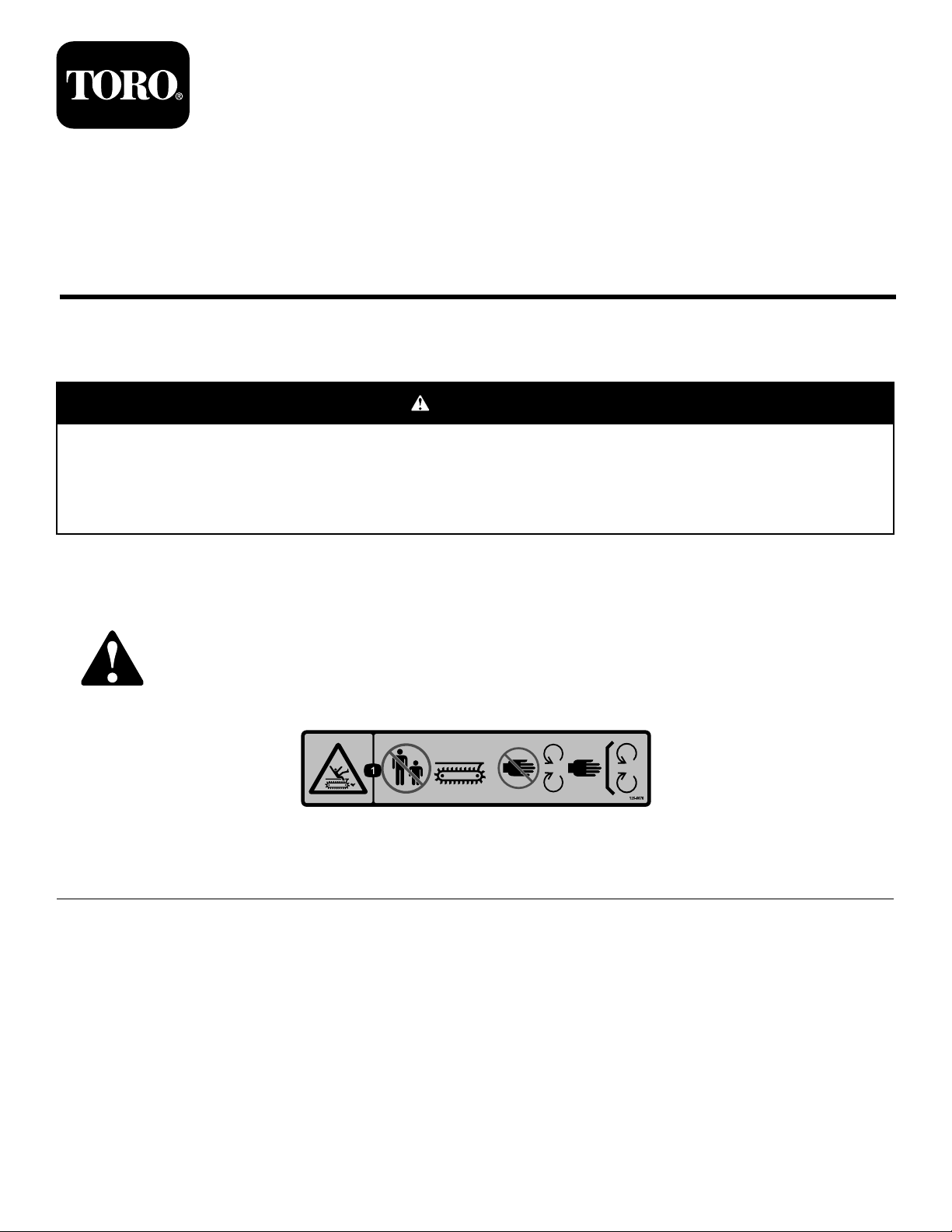
SafetyandInstructionalDecals
Safetydecalsandinstructionsareeasilyvisibletotheoperatorandarelocatednearanyareaofpotential
danger.Replaceanydecalthatisdamagedormissing.
125-6670
1.Cutting/dismembermenthazard,trencher—keepbystandersawayfromthetrencher;keepawayfrommovingparts;keepall
guardsandsafetiesinplace.
decal125-6670
©2016—TheT oro®Company
8111LyndaleAvenueSouth
Bloomington,MN55420
Registeratwww.T oro.com.
OriginalInstructions(EN)
PrintedintheUSA
AllRightsReserved
*3407-770*A
Page 2

Installation
LooseParts
Usethechartbelowtoverifythatallpartshavebeenshipped.
ProcedureDescription
1
2
3
4
Nopartsrequired
Crumber-tubeassembly
Crumber-plateassembly
Adapterttings
Hydraulichoses2
Hose-mountclamp2
Bolt(1/2x2-1/4inches)
Tubeclamp4
Coverplate
Bolt(5/16x1-1/2inches)
Bolt(3/8x2-1/2inches)
Hexnut(3/8inch)
Upperangleconduit1
Lowerangleconduit1
Tall,frontangleconduit
Tall,rearangleconduit1
Angletie1
Washer2
Bolt(1x2-1/2inches)
Hexnut(1/2inch)
Bolt(3/8x2-1/2inches)
Bolt(3/8-16x1inch)
Bolt(3/8x2-3/4inches)
Qty.
Use
–
1
1
2
4
2
2
3
3
1
2
5
3
1
1
Preparethemachine.
Installthecrumbertubeandplate
assembly.
Installthehydraulichoses.
Securethehydraulichoses.
5
Switch
1Installtheswitch.
2
Page 3
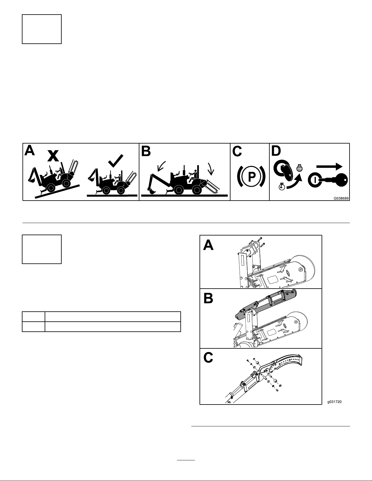
1
PreparingtheMachine
NoPartsRequired
Procedure
1.Parkthemachineonalevelsurface.
2.Lowertheattachments.
3.Engagetheparkingbrake.
4.Shutofftheengineandremovethekeyfromtheignitionswitch.
Figure1
g038689
2
InstallingtheCrumberTube andPlateAssembly
Partsneededforthisprocedure:
1
Crumber-tubeassembly
1
Crumber-plateassembly
Procedure
Important:Youshouldhaveeither2peopleorlifting
equipmenttoperformthisprocedure.
1.Loosenandremovethe4boltsandthe4locknutsthat
securethecrumber-mountingbracketstotheboom
(Figure2).
g031720
Figure2
2.Installthecrumber-tubeassemblyusingthe4locknuts
and4boltsthatyouremovedpreviously(Figure2).
3
Page 4

3.Securethecrumber-plateassemblytothecrumber-tube
assemblyasshowninFigure2.
3
InstallingtheHydraulicHoses
Partsneededforthisprocedure:
2
Adapterttings
2Hydraulichoses
2Hose-mountclamp
4
Bolt(1/2x2-1/4inches)
Procedure
g038691
Figure4
1.Installthe2adapterttingsontothemachine(Figure
3).
Figure3
6.Routetheotherhosefromtheupperportonthe
cylindertotherightportonthemachine(Figure5).
g038690
Figure5
g038692
2.Removethe4bolts,washers,andnuts(Figure3).
Note:Discardthebolts.
3.Securethehose-mountclampusing4bolts(1/2x
2-1/4inches)and4washersandthenutspreviously
removedasshowninFigure3.
4.Torquetheboltsto127to157N∙m(94to116ft-lb).
5.Route1ofthehosesfromthelowerportonthe
cylindertotheleftportonthemachine(Figure4).
4
Page 5

4
SecuringtheHydraulicHoses
Partsneededforthisprocedure:
4Tubeclamp
2
Coverplate
2
Bolt(5/16x1-1/2inches)
3
Bolt(3/8x2-1/2inches)
3
Hexnut(3/8inch)
1Upperangleconduit
1Lowerangleconduit
1
Tall,frontangleconduit
1Tall,rearangleconduit
1Angletie
2Washer
2
Bolt(1x2-1/2inches)
5
Hexnut(1/2inch)
3
Bolt(3/8x2-1/2inches)
1
Bolt(3/8-16x1inch)
1
Bolt(3/8x2-3/4inches)
Procedure
1.Securethehydraulichosestothetrencherdrivecover
using4tubeclamps,2coverplates,and2bolts(5/16x
1-1/2inches)asshowninFigure6.
g038693
Figure6
2.Torquetheboltsto31to37N∙m(23to28ft-lb).
3.Securetheupperandlowerangleconduitstothe
boom-mountplateontheframeusing3bolts(3/8x
2-1/2inches)and3hexnuts(3/8inch)asshownin
Figure7.
Note:Whentheboomisup,thereshouldnotbeany
slackinthehoses.
Note:Theboltsshouldbebehindthehydraulichoses.
g038694
Figure7
5
Page 6

4.Torquethe3bolts(3/8x2-1/2inches)to51to65
N∙m(38to48ft-lb).
5.Removetheboltsandnutsfromthecrumber-bracket
bar(Figure8).
Note:Discardthebolts.
11.Torquethe3bolts(3/8x2-1/2inches)to51to65
N∙m(38to48ft-lb).
12.Securetheangletietotheupperandlowerangle
conduitassemblyusing1bolt(3/8x2-3/4inches)and
1nut(3/8inch)asshowninFigure8.
13.Torquethebolt(3/8x2-3/4inches)to60to76N∙m
(44to56ft-lb).
5
InstallingtheSwitch
Partsneededforthisprocedure:
1
Switch
Procedure
1.Removethe6hex-angedbolts(12x30mm)that
securetherear-coverplatetotherearbulkheadofthe
machine,andremovethecoverplate(Figure9).
Figure8
6.Securetheangletietothetall,frontangleconduitusing
1bolt(3/8x1inch)and1nut(3/8inch)asshown
inFigure8.
7.Torquethebolt(3/8x1inch)to51to65N∙m(38to
48ft-lb).
8.Securethetall,frontangleconduittothecrumber
bracketusing2washersand2bolts(1x2-1/2inches)
andthe2boltspreviouslyremoved(Figure8).
9.Torquethe2bolts(1x2-1/2inches)to732to894
N∙m(540to660ft-lb).
10.Securethetall,rearangleconduittothetall,frontangle
conduitusing3bolts(3/8x2-1/2inches)and3nuts
(3/8inch)asshowninFigure8.
g031726
1.Bulkhead
2.Rear-coverplate
2.Cutthecabletiestoallowthewireharnessenough
slack.
6
Figure9
3.Hex-angedbolt(12x30
mm)
g025321
Page 7

3.Removetheplugandinstalltheswitch(Figure10).
Figure10
4.Connectthewireharnesslabeled“plowtilt”tothe
switch.
5.Testtheattachment:
•Pushtheswitchtowardtherearofthemachineto
lowertheattachment.
g031727
•Pushtheswitchtowardthefrontofthemachine
toraisetheattachment.
6.Checkforhydraulicleaks.
7.Installtherear-coverplatetotherearbulkhead
removedinstep1ofthisprocedure.
7
Page 8

 Loading...