

Page 1

BackhoeDriveReleaseKit
RT600TractionUnitwithBackhoe
ModelNo.25433
ModelNo.25433E
LooseParts
Usethechartbelowtoverifythatallpartshavebeenshipped.
FormNo.3377-954RevB
InstallationInstructions
Description
Valveassembly1
Hydraulictting(90degree)
Elbowtting(90degree)
Valvebracket1
Flange-headbolt(1/4x1-3/4inches)
Flangenut(1/4inch)
Flange-headbolt(M8x1-1/4inch)
Orice(0.080inch)
Elbowtting(45degree)
Hydraulichose2
Cabletie
Valveswitch1
Switchmountingbracket
Bolt(1/4x1/2inch)
Bolt(5/16x1inch)
Washer2
Nut(5/16inch)
10Ampfuse
Cableties
WARNING
Qty.
Use
2
1
2
2
2
1
2
5
1
2
2
2
1
5
Installthevalveassembly .
Installingthehydraulichoses.
Installthevalveswitch.
1.Parkthemachineonarm,levelsurface.
2.Lowerallattachmentstotheground.
CALIFORNIA
Proposition65Warning
Thisproductcontainsachemicalorchemicals
knowntotheStateofCaliforniatocausecancer,
birthdefects,orreproductiveharm.
InstallingtheValveAssembly
WARNING
Iftheenginehasbeenrunning,thehydraulicuid
andcomponentsmaybehotandcouldburnyou.
Allowthemachinetocoolbeforeperformingthis
procedure.
©2014—TheToro®Company
8111LyndaleAvenueSouth
Bloomington,MN55420
Registeratwww.T oro.com.
3.Turnofftheengine,removethekey,andallowthe
machinetocoolcompletely.
4.Removetheleft-side,enginecover;refertotheRT600
TractionUnitOperator’ sManualforinstructions.
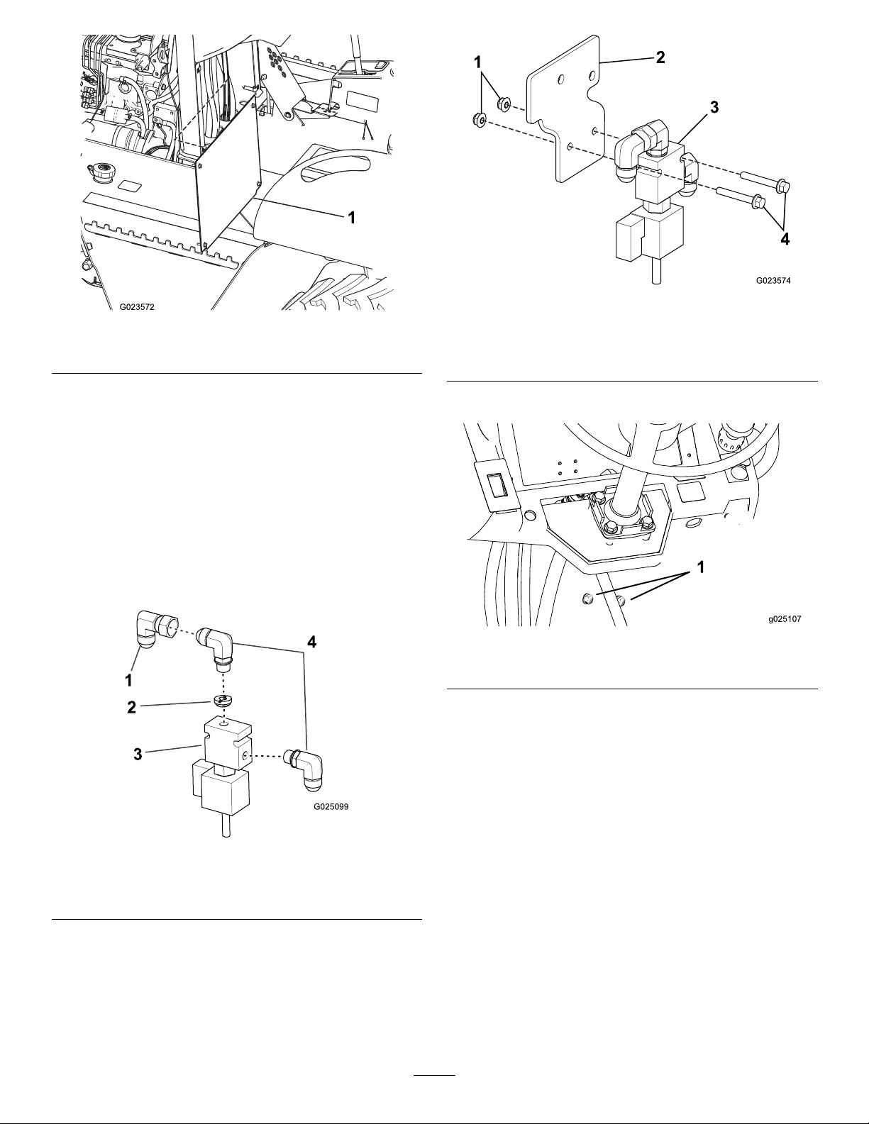
5.Loosenthe4boltssecuringtheaccesspanelinfrontof
thetractionunitseat,andremovethepanel(
OriginalInstructions(EN)
PrintedintheUSA
AllRightsReserved
*3377-954*B
Figure1).
Page 2
2
4
G025099
3
Figure3
1
g025107
Figure1
1.Accesspanel
6.Installtheoriceontothevalveassemblyasshownin
Figure2andhandtighten.
7.Installa90-degreeelbowttingintothesideofthe
valveassemblywiththeopenendpointingdown
(Figure2).
8.Installa90-degreeelbowttingintothetopofthe
valveassemblywiththeopenendpointingtotheleft
(Figure2).
9.Installa90-degreehydraulicttingontothetop,
90-degree,elbowttingwiththeopenendpointing
down(Figure2).
1.Flangenut(1/4inch)
2.Valvebracket
3.Valveassembly
4.Flange-headbolt(1/4x
1-3/4inches)
11.Removetheexistinghardwareandsetaside.
Figure4
1.Existinghardware
12.Installthevalvebrackettothemachineframebehind
theverticalhosesusing2ange-headbolts(M8x
1-1/4inch)andpreviouslyremovednutsasshownin
Figure5.
Figure2
1.90-degreehydraulictting
2.Orice4.90-degreeelbowtting
3.Valveassembly
10.Installthevalveassemblytothevalvebracketusing
2ange-headbolts(1/4x1-3/4inches)and2ange
nuts(1/4inch)(Figure3).
2
Page 3
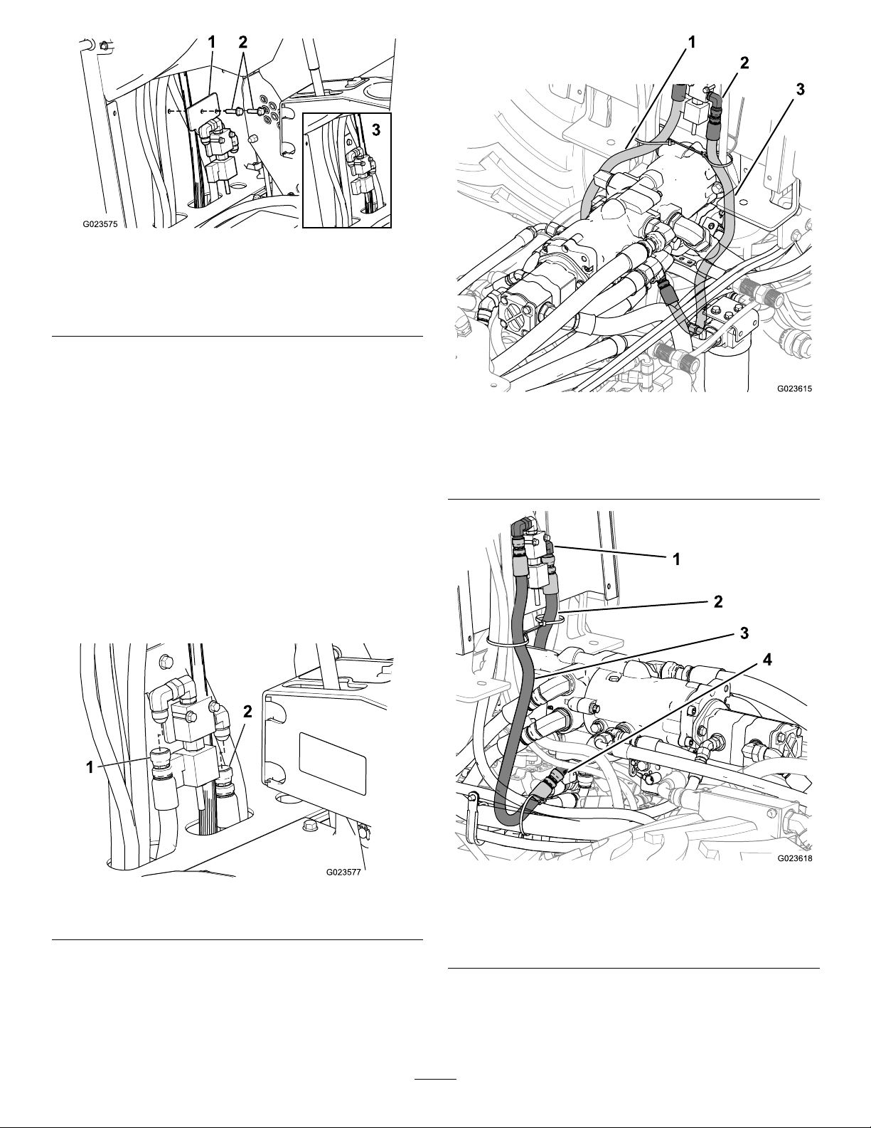
Figure5
1.Valvebracket3.Installbehindthevertical
hosesandcables
2.Flange-headbolt(M8x
1-1/4inch)
InstallingtheHydraulicHoses
1.Placealargedrainpanunderthecenterofthemachine
tocatchanyhydraulicuidthatdrainsoutduringthis
procedure.
2.Removetheooraccesspanelandfootpedal;refer
totheRT600TractionUnitOperator’sManualfor
instructions.
3.Threadthehydraulichosesdownthroughtheopenings
intheoorunderthevalve(Figure6),routingoneon
eachsideofthemainhydraulicmanifoldunderthe
oor.
4.Connecttheendsofthehosestotheopenendsofthe
90-degreettingsonthevalve(Figure6).
1.Lefthydraulichose
2.Valveassembly
Figure7
RightView
3.Righthydraulichose
Figure6
1.Hydraulichose—left
2.Hydraulichose—right
5.Routethelefthosethroughtheotherhosesunder
theunittotheleftplugonthebottomofthemain
hydraulicmanifold(Figure7andFigure8).
Figure8
LeftView
1.Valveassembly
2.Righthydraulichose
3.Lefthydraulichose
4.45-degreeelbowtting
6.Ensurethatthehosedoesnotcontactanyhard
surfaces,andsecureittotheotherhosesatthelevelof
theoorplatewithacabletie(Figure7andFigure8).
3
Page 4
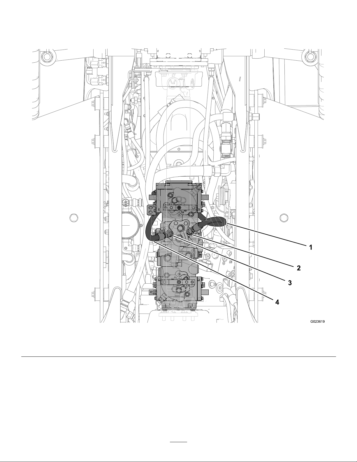
7.Removetheleftplugandallowanyescapinghydraulic
uidtodrainintothepan(Figure9).
8.Installa45-degreeelbowttingintotheopening,and
connectthelefthydraulichosetothetting(Figure9).
9.Repeatsteps5through8fortherighthydraulichose,
replacingtherightplugonthebottomofthemain
hydraulicmanifold.
Figure9
1.Lefthydraulichose3.Rightmanifoldport
2.Leftmanifoldport
4.Righthydraulichose
4
Page 5
InstallingtheValveSwitch
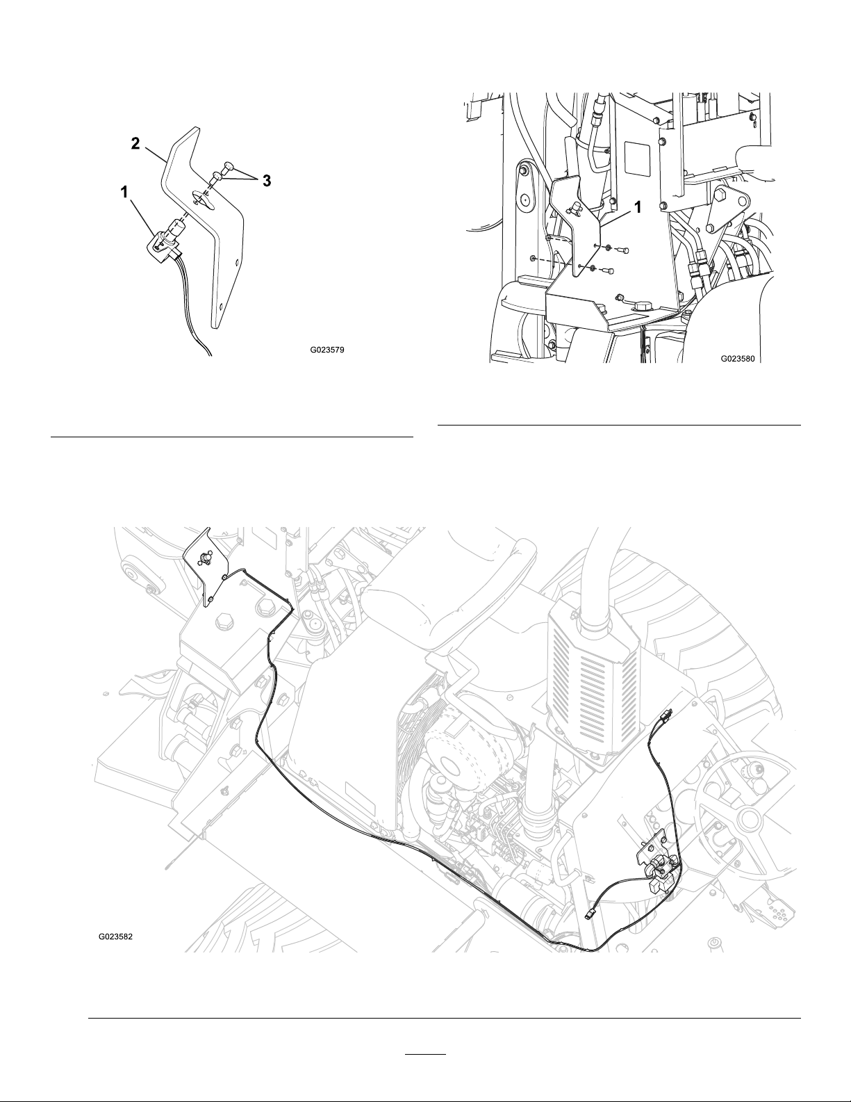
1.Installthevalveswitchontotheswitchmounting
bracketwith2bolts(1/4x1/2inch)asshowningure
Figure10.
Important:Ensurethatyoudonotpinchthe
wiresfromtheswitchbetweentheframeandthe
bracket.
Figure10
1.Valveswitch
2.Switchmountingbracket
3.Bolt(1/4x1/2inch)
2.Installtheswitchmountingbrackettothebackhoe
frametotheleftofthecontrolpanelusing2bolts
(5/15x1inch),2washers,and2nuts(5/16inch).
Figure11
1.Switchmountingbracket
3.Routethewiresfromtheswitchbehindandunder
thebackhoe,alongthesideofthetractionunit,into
theenginecompartmentalongwiththecurrentwiring
harness,andupintothecontrolconsoleofthetraction
unitasshowninFigure12andFigure13.
Topviewofmachine
Figure12
5
Page 6
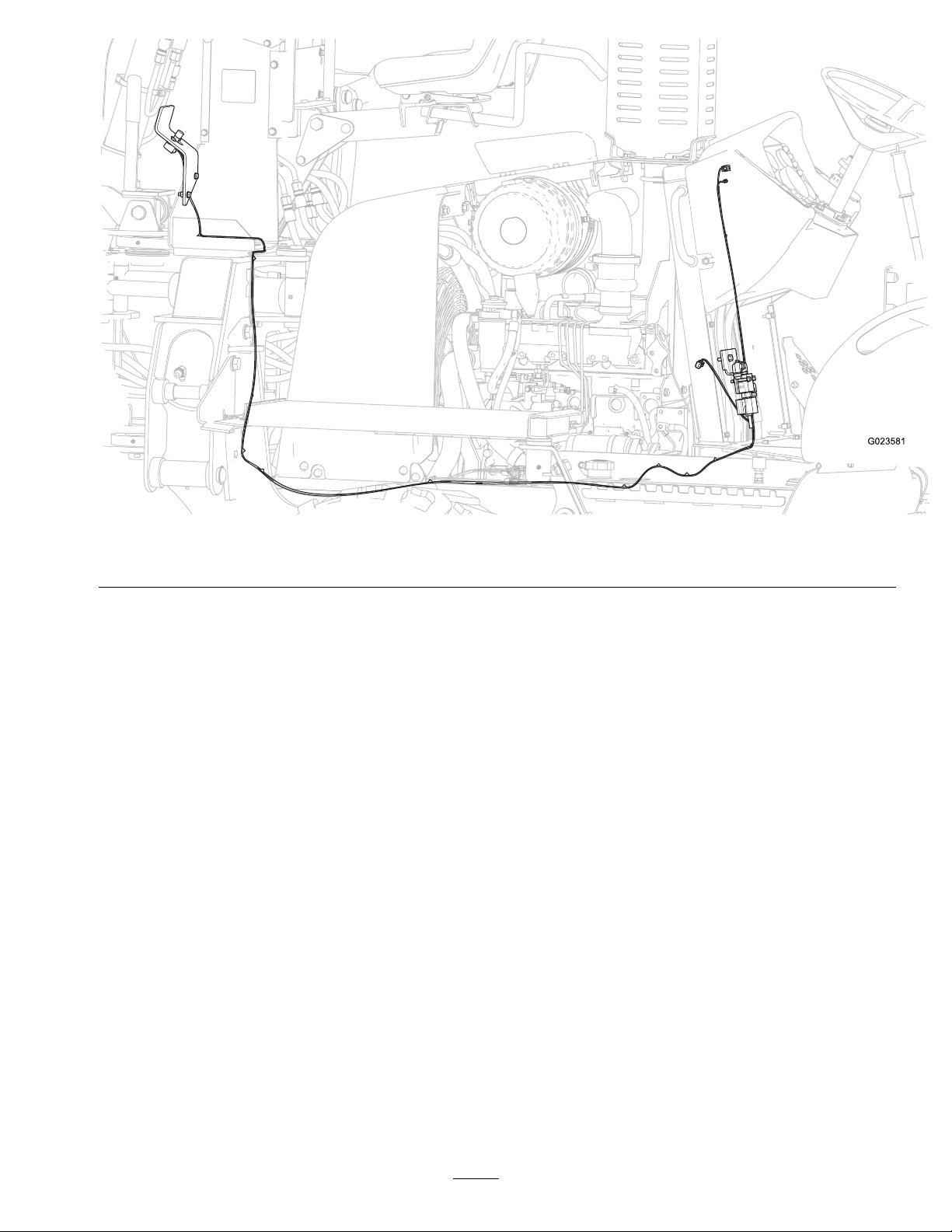
4.Secureharnessusingprovidedcableties.
Important:Makesuretoavoidsharpedgesand
movingparts.
5.Connectthetwo-pinconnectorfromthekitharnessto
thepreviouslyinstalledvalve.
6.Connectthespadeterminalattheendoftheharness
tothematingconnectoratthefuseblock.
7.Installthe10Ampfuseintotheappropriateopen
positioninthefuseblock.
8.Attachtheringterminaltothegroundblocknearthe
fuseblock.
9.Installthefootpedalandooraccesspanel.
Figure13
Sideviewofmachine
6
Page 7

Operation
UsingtheValve
Openingthevalveallowshydraulicuidtobypassthe
traction–unitdrivesystem,allowingyoutomovethemachine
usingthebackhoedipperstickandbucket,asfollows:
1.Raisethebackhoestabilizers.
2.Pressandholdthevalveswitchbuttontoreleasethe
parkingbrake.
Important:Releasingthevalveswitch
engagetheparkingbrake.
Presstheemergencystopbuttonifthemachine
beginstorolldownahill.
3.Usethebackhoedipperstickandthebuckettomove
themachineintoposition.
4.Releasethevalveswitchtoclosethevalve,lockingthe
traction–unitdrivesystem.
5.Lowerthebackhoestabilizers.
does not
WARNING
Ifyoudigwiththebackhoewiththestabilizers
raisedandthevalveopen,thetractionunitcould
moveortip,seriouslyinjuringyouorbystanders.
Alwaysclosethevalveandlowerthestabilizers
beforediggingwiththebackhoe.
7
Page 8

 Loading...