

Page 1

Installation
LooseParts
FormNo.3403-231RevA
QuadTrackKit
RT1200Trencher
ModelNo.25429
ModelNo.25429E
InstallationInstructions
WARNING
CALIFORNIA
Proposition65Warning
ThisproductcontainsachemicalorchemicalsknowntotheStateofCaliforniato
causecancer,birthdefects,orreproductiveharm.
Usethechartbelowtoverifythatallpartshavebeenshipped.
ProcedureDescription
1
2
3
Nopartsrequired
Bottomkingpin4
Socket-headbolt(14x40mm)
Kingpinshim—0.005inch(optional)
Kingpinshim—0.010inch(optional)
Kingpinshim—0.015inch(optional)
Socket-headbolt
Greasetting(90°elbow)
Nipple4
Coupler
Greasetting
Qty.
12
Use
–
4
8
8
8
4
4
4
Preparethemachine.
Installthebottomkingpin.
Installthegreasettingonthe
frame-mountbracket.
©2016—TheToro®Company
8111LyndaleAvenueSouth
Bloomington,MN55420
Registeratwww.T oro.com.
OriginalInstructions(EN)
PrintedintheUSA
AllRightsReserved
*3403-231*A
Page 2

ProcedureDescription
4
5
6
7
Topmountingplate(front,leftorrear,
right)
Topmountingplate(front,rightorrear,
left)
Frame-mountbracket(front,leftorrear,
right)
Frame-mountbracket(front,rightor
rear,left)
Mounting-plateshim(16gauge)
Mounting-plateshim(26gauge)
Bolt(16x60mm)
Bolt(14x70mm)
Bolt(14x60mm)
Bolt(14x55mm)
Bolt(14x30mm)
Flatwasher(14mm)
Nut(14mm)
Bolt(16x70mm)
Jamnut(16mm)
Locknut(16mm)
Bolt(14x40mm)
Jamnut(14mm)
Directionlimiter4
Direction-limitershim(16gauge)
Direction-limitershim(18gauge)
Direction-limitershim(26gauge)
Shim(11gauge)
Shim(16gauge)
Shim(18gauge)
Shim(26gauge)
Threadedrod4
Hex-headbolt(12x130mm)
Jamnut(16mm)
Flatwasher(16mm)
Locknut(16mm)
Flatwasher(12mm)
Locknut(12mm)
Boltlockingplate(16mm)
Boltlockingplate(14mm)
Lockwasher(10mm)
Bolt(10x20mm)
Chassisframe
Pivotaxle4
Pivot-axleplate4
Spacer
Retainingring4
Bolt(16x60mm)
Locknut(16mm)
Qty.
16
16
16
40
20
12
12
24
12
16
16
24
24
Use
2
2
2
2
8
Installtheframe-mountbracket,top
4
8
8
8
8
8
8
8
4
8
4
4
8
8
8
8
8
4
4
8
8
mountingbracket,andboltstops.
Installthedirectionlimiter.
Installtheboltlockingplates.
Installthechassisframe.
2
Page 3
ProcedureDescription
g028884
1
2
3
4
5
8
Sprocketthird
Bolt(16x40mm)
Washer48
Hexnut(16mm)
Track4
Qty.
12
24
24
Use
Installthesprocketthirdsandthetrack.
9
10
11
Note:Determinetheleftandrightsidesofthemachinefromthenormaloperatingposition.
Nopartsrequired
Nopartsrequired
Nopartsrequired
1
PreparingtheMachine
NoPartsRequired
Procedure
1.Parkthemachineonahard,levelsurface.
2.Setthefrontandrearwheelssothattheyarestraight
forward.
–
–
–
Checkandadjustthetoeofthetracks.
Alignthetracks.
Checkthetensionofthetracks.
3.Lowertheattachments,shutofftheengine,waitforall
movingpartstostop,andremovethekey.
4.Raisethemachineuntilallthewheelsareatleast15cm
(6inches)offtheground,andsupportthemachine
withjackstands.
Note:Usejackstandsratedforyourmachineand
attachment.RefertotheOperator’sManualforyour
machineandeachattachmenttodeterminethetotal
weight.
5.Removethelugnuts,washers,andwheelsfromthe
machine.
Note:Savethelugnutsandwheels.
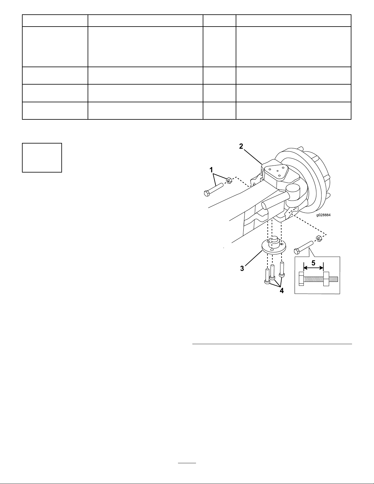
6.Measureandrecordthelengthoftheexposedbolton
eachsteeringlimiter(Figure1).
Note:Retainthesemeasurementstoinstallthebolt
andnutontoeachsteeringlimiterlater.
1.Boltandnut(2)
2.Steeringlimiter
3.Bottomkingpin(existing)
7.Removetheboltsandnutsfromthesteeringlimiter
(Figure1).
Note:Savetheboltsandnuts.
8.Supportthewheelhub.
9.Removethebottomkingpinbyremovingthe3bolts
thatholdit(Figure1).
Note:Savethebottomkingpinandthebolts.
Figure1
4.Boltssecuringthebottom
kingpin
5.Recordthismeasurement.
3
Page 4
2
g037538
1
g037890
1
2
2
InstallingtheBottomKingpin
Partsneededforthisprocedure:
4Bottomkingpin
4
Socket-headbolt(14x40mm)
8
Kingpinshim—0.005inch(optional)
8
Kingpinshim—0.010inch(optional)
8
Kingpinshim—0.015inch(optional)
12
Socket-headbolt
Procedure
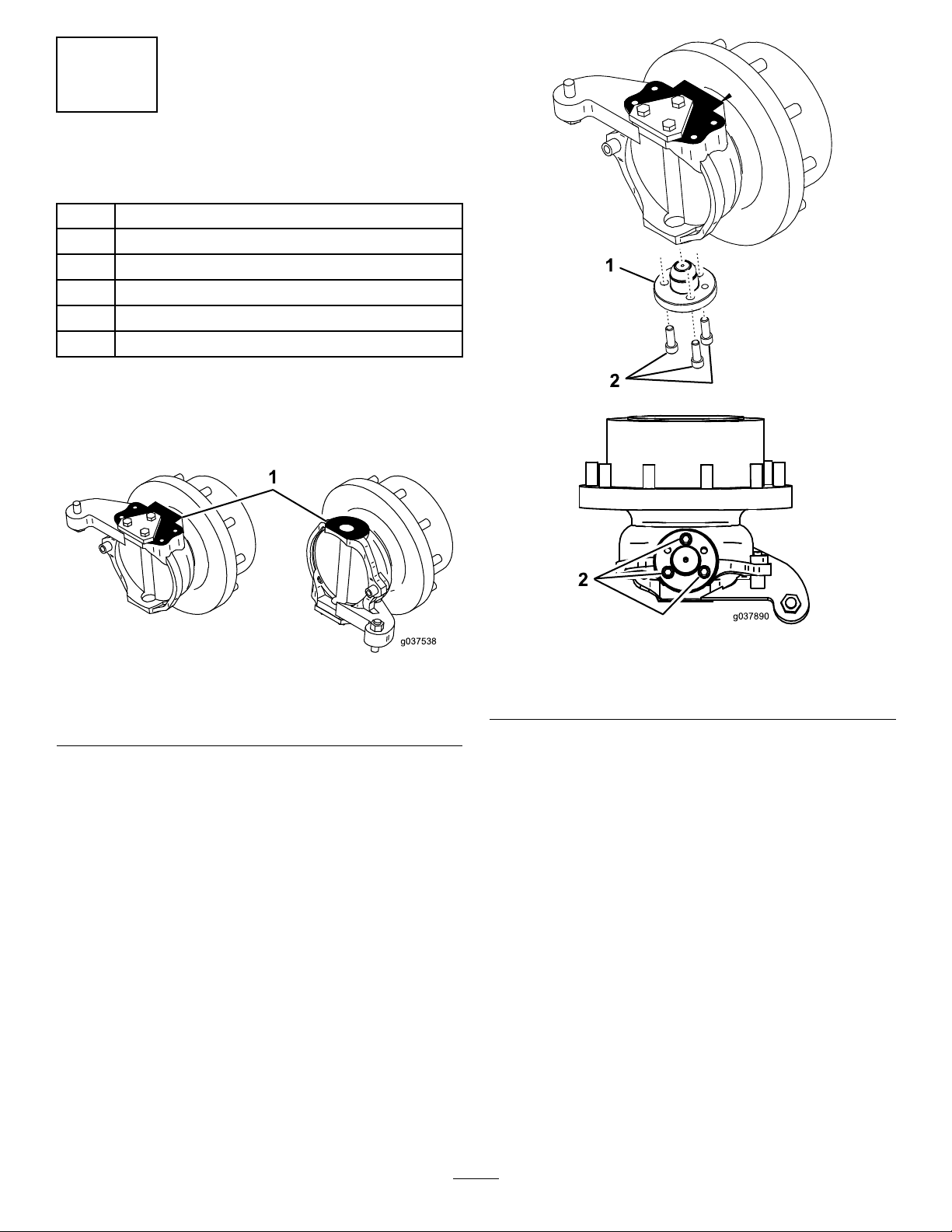
1.Removeanypaintandcleantheupperandlower
surfacesonthehubinthelocationsshowninFigure2.
Figure2
Top(left)andBottom(right)ViewsoftheHub
1.Cleanhere.
2.Installthebottomkingpintothebottomofthehub
with3socket-headboltsasshowninFigure3.
Figure3
Rear(above)andBottom(below)ViewsoftheHub
1.Bottomkingpin
3.Torquethesocket-headboltsto135to165N∙m(100
to120ft-lb).
4.Adjustthebottomkingpinaccordingtothe
manufacturer’sinstructions.
5.Removeanddiscard2ofthe3socket-headboltsfrom
thebottomkingpinatthelocationsshowninFigure4.
2.Socket-headbolts
4
Page 5
g037589
1
2
3
g037959
2
3
4
5
InstallingtheGreaseFittingon
theFrame-MountBracket
Partsneededforthisprocedure:
4
Greasetting(90°elbow)
4Nipple
4
Coupler
4
Greasetting
Procedure
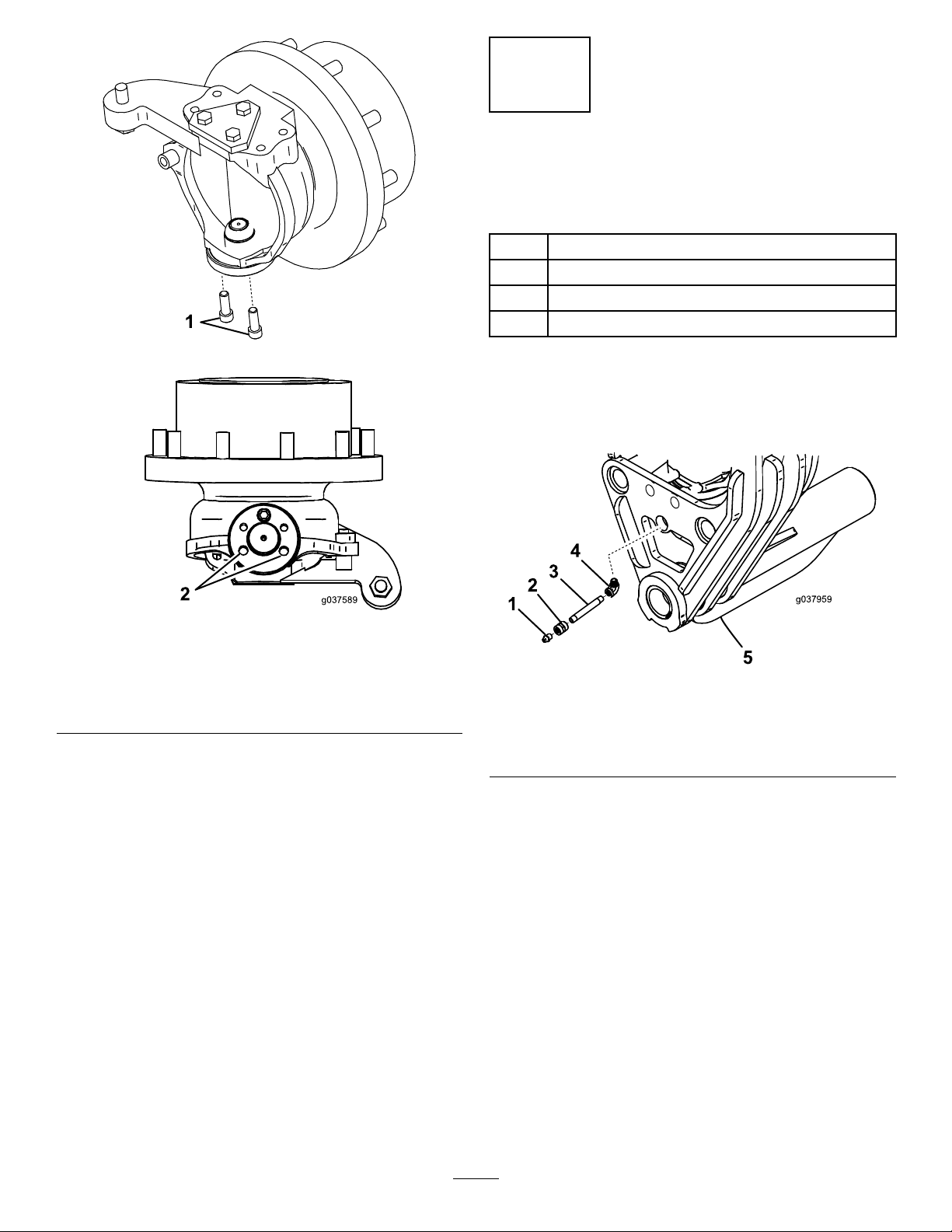
Assemblethegrease-ttingcomponentsandinstallthe
assemblyintotheframe-mountbracketasshowninFigure5.
Figure4
Rear(above)andBottom(below)ViewsoftheHub
1.Removethese2
socket-headbolts.
2.Thesearetheholesfrom
whichyouremovethe2
socket-headbolts.
Figure5
1.Greasetting4.90°elbowtting
2.Coupler
3.Nipple
5.Frame-mountbracket
5
Page 6

4
g037590
1
2
InstallingtheFrame-Mount
Bracket,TopMounting
Bracket,andBoltStops
Partsneededforthisprocedure:
2
Topmountingplate(front,leftorrear,right)
2
Topmountingplate(front,rightorrear,left)
2
Frame-mountbracket(front,leftorrear,right)
2
Frame-mountbracket(front,rightorrear,left)
8
Mounting-plateshim(16gauge)
16
Mounting-plateshim(26gauge)
16
Bolt(16x60mm)
16
Bolt(14x70mm)
4
Bolt(14x60mm)
8
Bolt(14x55mm)
8
Bolt(14x30mm)
40
Flatwasher(14mm)
20
Nut(14mm)
8
Bolt(16x70mm)
8
Jamnut(16mm)
8
Locknut(16mm)
8
Bolt(14x40mm)
8
Jamnut(14mm)
InstallingtheFrame-MountBracket
Note:Thereare2typesofframe-mountbrackets,abracket
forthefront,lefttrackandtherear,righttrack;andtheother
bracketforthefront,righttrackandtherear,lefttrack.
Figure6
1.Bolts—14x60mm(4)
2.Topmountingplate
2.Looselyinstalltheframe-mountbracketontothehub
usingabolt(14x70mm)andanut(14mm)through
thetopmountingframeand2bolts(14x55mm)and
2bolts(14x30mm)upthroughthebottomkingpinas
showninFigure7.
Note:Removethepaintfromthetopsurfaceofthe
frame-mountbracketifnecessary(seetheblackareaon
thetopsurfaceofthebracketasshowninFigure7).
Note:Useaoorjacktoholdtheframe-mount
bracketinplacewhileyouinstallit.
Important:Y ouwillneed2peopletoperformthis
procedure.
1.Looselyinstallthetopmountingplatetothehubwith
4bolts(14x60mm)asshowninFigure6.
Note:Removethepaintfromthebottomofthetop
mountingplateifnecessary.
Note:Donottorquethebolts.
6
Page 7

g037910
1
2
3
4
5
6
X
X
g037541
1
2
Figure8
BottomViewofHub
Figure7
1.Bolt(14x70mm)5.Bolt(14x55mm)
2.Topmountingplate
3.Nut(14mm)7.Bolt(14x30mm)
4.Frame-mountbracket
3.Removethetopmountingplatebyremovingthe4
bolts(14x60mm)and1bolt(14x70mm)and1nut
(14mm)thatyouinstalledinsteps1and2.Retainthe
topmountingplateandfastenerstoinstalllater.
4.Ensurethatthehubfaceisparallelwiththeedgeofthe
tubeontheframe-mountbrackettowithin1.6mm
(1/16inch);notethedimension“X”oneithersideof
thehubinFigure8.
6.Bolt(14x30mm)
8.Bolt(14x55mm)
1.Hubface2.Edgeofthetubeonthe
frame-mountbracket
5.Torquethe2bolts(14x55mm)and2bolts(14x30
mm)to135to165N∙m(100to120ft-lb).
InstallingtheTopMountingBracket
1.Insertthemounting-plateshims(16gaugeand26
gauge)asneededtofullyllthegapbetweenthetop
offrame-mountbracketandthebottomofthetop
mountingbracketasshowninFigure9.
7
Page 8

g037592
1
2
3
4
5
6
7
8
4
InstallingtheBoltStops
g03791 1
1
2
3
4
5
Installthe2bolts(14x40mm),2jamnuts(14mm),2bolts
(16x70mm),2jamnuts(16mm),and2locknuts(16mm)
intotheframe-mountbracketfromtheinboardsideasshown
inFigure10.
Figure10
1.Bolts(16x60mm)
2.Bolt(14x60mm)6.Shims(16gauge)
3.Bolts(14x70mm)7.Shimplates(useas
4.Flatwasher—(14mm)8.Locknut(14mm)
Figure9
5.Topmountingplate
needed)
2.Installthetopmountingplatetotheframe-mount
bracketusing4bolts(16x60mm)thatyoutemporarily
usedintheprevioussetupprocedure,1bolt(14x60
mm),4bolts(14x70mm),10atwashers(14mm),
and5nuts(14mm)asshowninFigure9.
3.Torquethefastenersasfollows:
•Bolt(16x60mm):220to260N∙m(160to190
ft-lb)
1.Jamnut—14mm(2)4.Jamnut—16mm(2)
2.Bolt—14x40mm(2)5.Locknut—16mm(2)
3.Bolt—16x70mm(2)
•Bolt(14x60mm):135to165N∙m(100to120
ft-lb)
•Bolt(14x70mm),atwasher(14mm),andnut
(14mm):135to165N∙m(100to120ft-lb)
Important:Ensurethatthereisfullcontact
betweenallthepartsafteryoutorquethefasteners.
8
Page 9

5
12
1
2
3
4
5
6
7
8
9
10
11
5
10
g037960
InstallingtheDirectionLimiter
Partsneededforthisprocedure:
4Directionlimiter
4
Direction-limitershim(16gauge)
8
Direction-limitershim(18gauge)
4
Direction-limitershim(26gauge)
4
Shim(11gauge)
8
Shim(16gauge)
8
Shim(18gauge)
8
Shim(26gauge)
4Threadedrod
12
Hex-headbolt(12x130mm)
8
Jamnut(16mm)
8
Flatwasher(16mm)
12
Locknut(16mm)
24
Flatwasher(12mm)
12
Locknut(12mm)
Procedure
1.Installthedirectionlimiterusingthehardwareand
shimsasshowninFigure11.
Note:Usetheshimsasrequiredtoensurethatthere
isfullcontactbetweenallsurfacesbeforetorquingthe
fasteners.Removeanypaintfromtheinsidesurfacesof
theframe-mountbracketthatcontacttheshims.You
mayneedtoremovematerialfromtheshim(s)toll
anygapsaroundtheframe-mountbracket.
Figure11
1.Shims(1 1,16,18,and26
gauge;useasneeded)
2.Direction-limitershim(16
gauge)
3.Direction-limitershims(26
gauge)
4.Direction-limitershim(18
gauge)
5.Locknut(16mm)12.Bolt—12x130mm(3)
6.Flatwasher(16mm)
7.Threadedrod
8.Jamnut(16mm)
9.Locknut(12mm)
10.Flatwasher—12mm(6)
11.Directionlimiter
13.Direction-limiterassembly
(detail)
2.Torquethebolts(12x130mm)to85to105N∙m(60
to75ft-lb).
9
Page 10

6
g037594
1
2
3
4
1
2
InstallingtheBoltLocking
Plates
Partsneededforthisprocedure:
16
Boltlockingplate(16mm)
16
Boltlockingplate(14mm)
24
Lockwasher(10mm)
24
Bolt(10x20mm)
Procedure
1.Installthe4boltlockingplates(16mm)and4bolt
lockingplates(14mm)overtheboltssecuringthetop
mountingbrackettotheframe-mountbracketusing
thehardwareshowninFigure12.
Note:Ifalockingplatedoesnotalignwiththebolts,
iptheplateoveranditshouldalign.
Figure12
1.Bolt—10x20mm(6)
2.Lockwasher—10mm(6)
2.Torquethebolts(10x20mm)to50to60N∙m(35
to45lb-ft).
3.Boltlockingplate—16mm
(4)
4.Boltlockingplate—14mm
(4)
10
Page 11

7
1
g037595
1
g037602
g037597
1
g037598
1
3
4
5
6
7
8
InstallingtheChassisFrame
Partsneededforthisprocedure:
4
Chassisframe
4Pivotaxle
4Pivot-axleplate
4
Spacer
4Retainingring
8
Bolt(16x60mm)
8
Locknut(16mm)
Procedure
1.Positionthechassisframesothatthetrackadjusters
arelocatedawayfromthecenterofthemachineas
showninFigure13andFigure14.
Note:Figure13andFigure14showonlytheouter
trackadjusters;theinnertrackadjustersarenotshown.
Figure15
Onlytheoutertrackeradjusterisshown.
1.Track-adjusterbolt(2)
3.Installthechassisframeontotheframe-mountbracket
usingthepivotaxle(Figure16).
Note:Useahoisttoliftandpositionthechassisframe.
Note:Ensurethatthegreasettingsonthechassis
framefaceoutward.
Forthefront,lefttrackandtherear,righttrack
1.Outertrackadjuster(2)
Forthefront,righttrackandtherear,lefttrack
1.Outertrackadjuster(2)
Figure13
Figure14
Figure16
1.Retainingring
2.Spacer
3.Tubeoftheframe-mount
bracket
4.Locknut—16mm(2)8.Bolt—16x60mm(2)
5.Chassisframe
6.Pivotaxle
7.Pivot-axleplate
4.Installthepivotaxleisfullythroughthechassisframe
(Figure16).
5.Installthespacerandretainingringontheendofthe
pivotaxle(Figure16).
6.Securetheoutsideendoftheaxlepivotwiththe
pivot-axleplate,2bolts(16x60mm)and2locknuts
(16mm).
2.Turnboththeinnerandoutertrack-adjusterbolts
(Figure15)sothattheadjustersmoveinward,making
iteasiertoinstallthetracklater.
Note:Torquethe2boltsand2nutsto255to311
N-m(188to230ft-lb).
7.Repeatthisprocedurefortheremaining3tracks.
11
Page 12

8
InstallingtheSprocketThirds
andtheTrack
Partsneededforthisprocedure:
12
Sprocketthird
24
Bolt(16x40mm)
48Washer
24
Hexnut(16mm)
4Track
Procedure
Figure18
1.Nut3.Wheellug
2.Sprocketthird
1.Alignthe3sprocketthirdstogetherontheoor
(Figure17).
Note:Thisisanecessarystepbecausethesprocket
thirdsarenotsymmetricalandthereforettogether
only1way.
Figure17
2.Assembleasprocketthirdontothewheellugsand
looselyinstallthelugnuts(Figure18).
Note:Itiseasiertoslidethesprocketthirdbetween
themaintubeandthetrack-adjustermechanism.
3.Installthetrackoverthesprocketsandunderthe
chassisframe.
Note:Notetheorientationofthetrackpattern.To
makeinstallingthetrackeasier,applysoapywateror
mineraloiltotheteethofthetrack.
Note:Usingahoisttoliftthetrackmakesinstalling
iteasier.
4.Startthemachineandrotatethesprocketthirdtothe
topposition.
5.Assembleanothersprocketthird,rotateittotheside
position,andlooselyinstallthelugnuts.
6.Assemblethenalsprocketthirdandlooselyinstall
thelugnuts.
7.Securethesprocketstogetherusing6setsoffasteners
thatconsistofabolt(16x40mm),2washers,anda
hexnut(16mm)each(Figure19).
Note:Torquetheboltsandnutsto255to311N-m
(188to230ft-lb).
12
Page 13

Figure19
g029074
1
2
3
4
Thenalsprocketthirdisnotshownforthepurposeof
clarity.
9
CheckingandAdjustingthe
ToeoftheTracks
NoPartsRequired
Procedure
Note:Checktoensurethatthecenterlinesofthetrackson
eachaxleareapproximatelyparallel,withouttoe-inortoe-out.
Iftheyarenot,performtheprocedurethatfollows.
1.Spocketthird4.Nut(16mm)
2.Bolt(16x40mm)5.Onesetoffasteners—bolt
(1),washers(2),andnut
(1)
3.Washers
8.Checkthetensionofthetrack;referto11Checking
theTensionoftheTracks(page15).
9.Turnboththeinnerandoutertrack-adjusterbolts
outward(Figure20)thesameamountsothatthe
tensionacrossthetrackisequalwhileyousecurethe
trackinplace.
Forpropertension,thereshouldbeagapbetweenthe
bottomoftheframerailandtheinsideofthetrack
of8.3cm(3-1/4inches).
1.Placeawrenchontheatsurfacesonthetie-rodend
(Figure21).
Figure21
1.Threadedadjuster3.Holdawrenchhereonthe
2.Jamnut
tierodend.
4.Steeringlimiter
Figure20
1.Trackadjusterbolt(2)
10.Repeatthisprocedurefortheremaining3tracks.
2.Movethetrackadjuster
boltsevenlyoutward
2.Useasecondwrenchtoloosenthejamnut(Figure21).
3.Movethesecondwrenchtotheatsurfacesofthe
threadedadjuster(Figure21)androtatethethreaded
adjusterinwardoroutwarduntilthetracksare
approximatelyparallel.
Note:Rotatethethreadedadjusterclockwiseto
shortenit;rotateitcounterclockwisetolengthenit.
4.Withtherstwrenchstillinplace,tightenthejamnut
securely.
5.Adjustthesteeringlimiter(Figure21)asneededto
preventthetrackfrominterferingwiththemachine.
Note:Thedistancefromthebaseofthecastingto
theendoftheboltshouldbeapproximately13.7cm
(5-3/8inches).
6.Lowerthemachinetotheground.
13
Page 14

10
1
2
3
g028918
5
1
2
3
4
g028917
6
AligningtheTracks
NoPartsRequired
Procedure
Todeterminewhetherthetracksarecorrectlyaligned,start
theengine,rotatethetrackatleast6times,andcheckwhether
thewheelsremaincenteredbetweentheteethofthetrack
(Figure22).
Note:Thewheelsshouldremaincenteredbetweentheteeth
ofthetrack.
Figure23
Backviewoftrack
1.Directionoftrackmigration4.Outsidetrackadjuster
2.Exteriorside5.Insidetrackadjuster
3.Interiorside6.Track
Figure22
1.Trackmigration3.Wheels
2.Teeth
Ifthetrackbeginstomigrateoffthewheels,increasethe
tensiononthesideofthetrackwhereittendstomigrate
(Figure23)usingthefollowingprocedure:
1.Movethetrackadjusteronthesidewherethetrackis
migratingoffthewheelsbyturningthetrack-adjuster
boltoutward6mm(1/4inch);refertoFigure24.
Figure24
Sideviewoftrack
1.Track-adjusterbolt(2)
2.Movethetrackadjuster
outward6mm(1/4inch)
2.Starttheengine,rotatethetrackatleast6times,and
14
checkwhetherthewheelsremaincenteredbetween
theteethofthetrack.
Note:Ifthetrackisalreadystretchedtoitsmaximum,
reducethetensionby6mm(1/4inch)ontheinner
trackadjuster.
Page 15

3.Repeatthisprocedureuntilthewheelsremaincentered
g037558
1
2
betweentheteethofthetrack.
11
CheckingtheTensionofthe
Tracks
NoPartsRequired
Figure25
Procedure
Important:Itisnormalforthetrackstostretchthe
rsttimethatyouusethem.Adjustthetensionofthe
tracksaftertherst25operatinghourstopreventthe
componentsfromwearingprematurely.Improperly
tensionedtrackscanleadtoprematurewearingorloss
oftrackcomponents.Checkthetensionofthetracks
regularly.
TrackTension
ToolooseThetrack
TootightThetracklosesa
Signs
disengagesinthe
tractionteethofthe
sprocketwheel.
Thereisa
signicantincrease
invibration.
signicantamount
ofpowerand
revolutionspeed.
1.Raisethemachineandpositionithorizontally.
Possible
Consequences
Thetrackteeth
wearprematurely .
Thetrack
losestraction.
Thereisarisk
ofthetrackcoming
off.
Thetrack,ball
bearings,sprocket
wheelstems,
andplanetary
gearboxallwear
prematurely.
1.Gap—83to89mm(3-1/4
to3-1/2inches)
2.Roundbar
5.Repeatthismeasurement5pitchesaheadand5pitches
afterthelocationofthemodel/serialnumberplate.
Note:Rotatethetracksothatallthesepositionsare
locatedbetweenthe2smallerwheels.
Note:Themaximumallowabledistanceshouldbe
within83to89mm(3-1/4to3-1/2inches)fromthe
trackinnersurfaceandthetrackbeam.
6.Adjusttheadjustersforthetrackasneeded.
7.Lowerthemachinetotheground.
2.Rotatethetracksothatthemodel/serialnumberplate
ofthetrackisbetweenthesmallerwheels.
3.Puta45kg(100lb)roundbarintothetrackbetween
thelugsandbetweenthe2smallerwheels.
Note:Asteelbar6.35cm(2-1/2inches)indiameter
and183cm(72inches)longworks.
4.Measurethedistance(gap)betweentheinnersurface
ofthetrackandthetrackbeam(Figure25).
15
Page 16

TheToroWarranty
AOne-YearLimitedWarranty
CompactUtilityEquipment
(CUE)Products
ConditionsandProductsCovered
TheT oroCompanyanditsafliate,T oroW arrantyCompany,pursuantto
anagreementbetweenthem,jointlywarrantyourT oroCompactUtility
Equipment(“Product”)tobefreefromdefectsinmaterialsorworkmanship.
Thefollowingtimeperiodsapplyfromthedateofpurchase:
ProductsWarrantyPeriod
ProSneak
CompactT oolCarriers,
Trenchers,StumpGrinders,
andAttachments
KohlerEngines3years
AllotherEngines2years
Whereawarrantableconditionexists,wewillrepairtheProductatnocost
toyouincludingdiagnosis,labor,andparts.
*
SomeenginesusedonToroProductsarewarrantedbytheenginemanufacturer .
1yearor1000operatinghours,
whicheveroccursrst
*
*
InstructionsforObtainingWarrantyService
IfyouthinkthatyourToroProductcontainsadefectinmaterialsor
workmanship,followthisprocedure:
1.ContactanyAuthorizedT oroCompactUtilityEquipment(CUE)
ServiceDealertoarrangeserviceattheirdealership.T olocatea
dealerconvenienttoyou,accessourwebsiteatwww.T oro.com.Y ou
mayalsocallourToroCustomerCareDepartmenttollfreeatthe
numberbelow.
2.Bringtheproductandyourproofofpurchase(salesreceipt)tothe
ServiceDealer.
3.IfforanyreasonyouaredissatisedwiththeServiceDealer’s
analysisorwiththeassistanceprovided,contactusat:
SWSCustomerCareDepartment
ToroW arrantyCompany
811 1LyndaleAvenueSouth
Bloomington,MN55420-1196
TollFree:888-384-9940
OwnerResponsibilities
YoumustmaintainyourT oroProductbyfollowingthemaintenance
proceduresdescribedintheOperator’sManual.Suchroutinemaintenance,
whetherperformedbyadealerorbyyou,isatyourexpense.Parts
scheduledforreplacementasrequiredmaintenance(“MaintenanceParts”),
arewarrantedfortheperiodoftimeuptothescheduledreplacementtime
forthatpart.Failuretoperformrequiredmaintenanceandadjustmentscan
begroundsfordisallowingawarrantyclaim.
ItemsandConditionsNotCovered
Notallproductfailuresormalfunctionsthatoccurduringthewarrantyperiod
aredefectsinmaterialsorworkmanship.Thisexpresswarrantydoesnot
coverthefollowing:
•Productfailureswhichresultfromtheuseofnon-T ororeplacement
parts,orfrominstallationanduseofadd-on,modied,orunapproved
accessories
•Productfailureswhichresultfromfailuretoperformrequired
maintenanceand/oradjustments
•ProductfailureswhichresultfromoperatingtheProductinanabusive,
negligentorrecklessmanner
•Partssubjecttoconsumptionthroughuseunlessfoundtobedefective.
Examplesofpartswhichareconsumed,orusedup,duringnormal
productoperationinclude,butarenotlimitedto,belts,wipers,spark
plugs,tires,lters,gaskets,wearplates,seals,O-rings,drivechains,
clutches.
•Failurescausedbyoutsideinuence.Itemsconsideredtobeoutside
inuenceinclude,butarenotlimitedto,weather,storagepractices,
contamination,useofunapprovedcoolants,lubricants,additives,or
chemicals,etc.
•Normal“wearandtear”items.Normal“wearandtear”includes,butis
notlimitedto,wornpaintedsurfaces,scratcheddecals,etc.
•Repairsnecessaryduetofailuretofollowrecommendedfuel
procedure(consultOperator'sManualformoredetails)
–Removingcontaminantsfromthefuelsystemisnotcovered
–Useofoldfuel(morethanonemonthold)orfuelwhichcontains
morethan10%ethanolormorethat15%MTBE
–Failuretodrainthefuelsystempriortoanyperiodofnon-use
overonemonth
•Anycomponentcoveredbyaseparatemanufacturer’swarranty
•Pickupanddeliverycharges
GeneralConditions
RepairbyanAuthorizedT oroCompactUtilityEquipment(CUE)Service
Dealerisyoursoleremedyunderthiswarranty .
NeitherTheToroCompanynorToroWarrantyCompanyisliablefor
indirect,incidentalorconsequentialdamagesinconnectionwiththe
useoftheToroProductscoveredbythiswarranty,includingany
costorexpenseofprovidingsubstituteequipmentorserviceduring
reasonableperiodsofmalfunctionornon-usependingcompletionof
repairsunderthiswarranty .Allimpliedwarrantiesofmerchantability
andtnessforusearelimitedtothedurationofthisexpresswarranty.
Somestatesdonotallowexclusionsofincidentalorconsequential
damages,orlimitationsonhowlonganimpliedwarrantylasts,sothe
aboveexclusionsandlimitationsmaynotapplytoyou.
Thiswarrantygivesyouspeciclegalrights,andyoumayalsohaveother
rightswhichvaryfromstatetostate.
ExceptfortheenginewarrantycoverageandtheEmissionswarranty
referencedbelow,ifapplicable,thereisnootherexpresswarranty.The
EmissionsControlSystemonyourProductmaybecoveredbyaseparate
warrantymeetingrequirementsestablishedbytheU.S.Environmental
ProtectionAgency(EPA)ortheCaliforniaAirResourcesBoard(CARB).
ThehourlimitationssetforthabovedonotapplytotheEmissions
ControlSystemWarranty.RefertotheCaliforniaEmissionControl
WarrantyStatementsuppliedwithyourProductorcontainedintheengine
manufacturer’sdocumentationfordetails.
CountriesOtherthantheUnitedStatesorCanada
CustomerswhohavepurchasedT oroproductsoutsidetheUnitedStatesorCanadashouldcontacttheirT oroDistributor(Dealer)toobtainguarantee
policiesforyourcountry ,province,orstate.IfforanyreasonyouaredissatisedwithyourDistributor'sserviceorhavedifcultyobtainingguarantee
information,contacttheT oroimporter.Ifallotherremediesfail,youmaycontactusatT oroWarrantyCompany .
AustralianConsumerLaw:AustraliancustomerswillnddetailsrelatingtotheAustralianConsumerLaweitherinsidetheboxoratyourlocalT oro
Dealer.
374-0261RevG
 Loading...