

Page 1

FormNo.3394-785RevA
Back-UpAlarmKit
RT1200Trencher
ModelNo.25427
ModelNo.25427E
InstallationInstructions
Note:InstallsoftwarerevisionGorhigherbeforeinstallingthiskit.RefertoyourAuthorizedToroDealerforthesoftware
update.
WARNING
CALIFORNIA
Proposition65Warning
ThisproductcontainsachemicalorchemicalsknowntotheStateofCaliforniato
causecancer,birthdefects,orreproductiveharm.
Installation
LooseParts
Usethechartbelowtoverifythatallpartshavebeenshipped.
Description
Bracket1
Alarm1
Bolt(M6-1x20)
Nut(M6-1)
Wireharness1
Cableties
Nopartsrequired
Qty.
Use
2
2
6
–
Installthealarm.
Installthewireharness.
Checkthealarm.
©2015—TheToro®Company
8111LyndaleAvenueSouth
Bloomington,MN55420
Registeratwww.T oro.com.
OriginalInstructions(EN)
PrintedintheUSA.
AllRightsReserved
*3394-785*A
Page 2
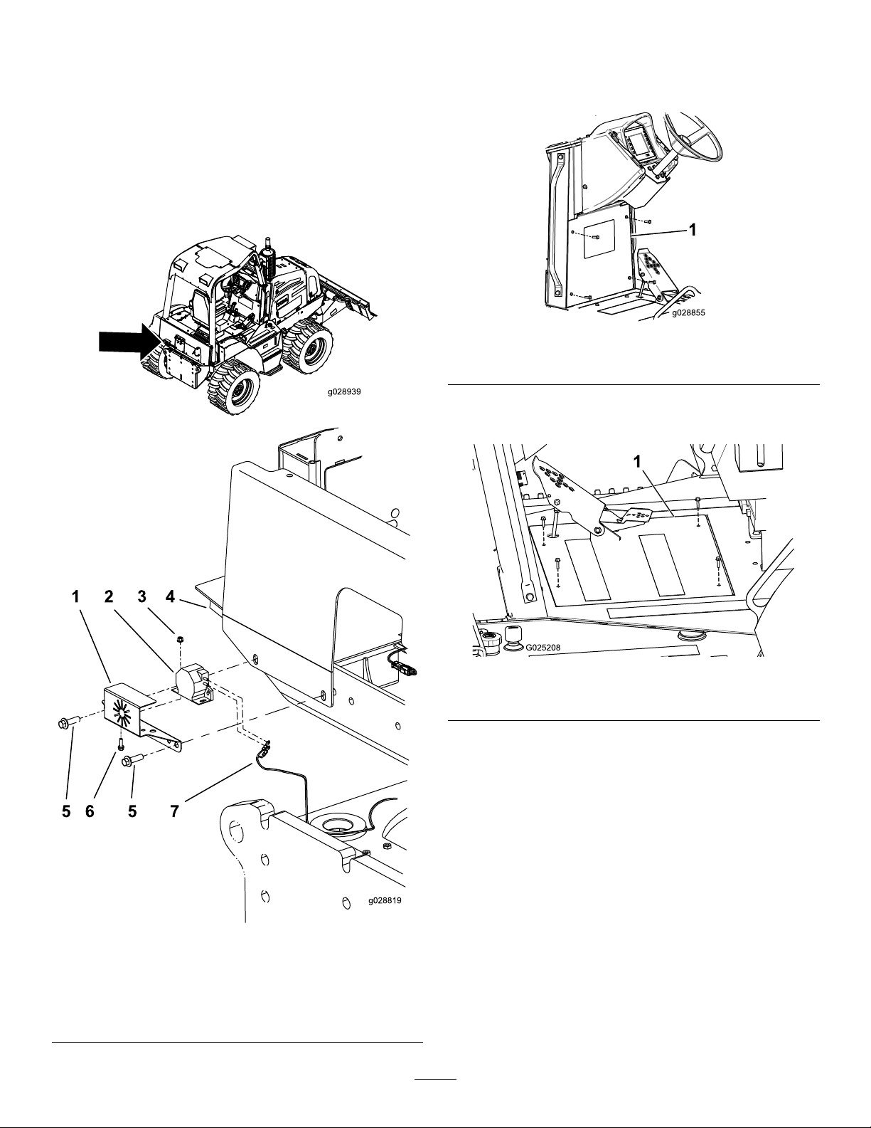
InstallingtheAlarm
g028939
InstallingtheWireHarness
1.Removetheexistingboltsfromthebackofthe
machine(Figure1).
2.Installthealarmtothebracketwith2bolts(M6-1x20)
and2nuts(M6-1)(Figure1).
3.Applythread-lockingcompoundontotheexisting
bolts(Figure1).
4.Installthebrackettotherearofthemachinewiththe
existingbolts(Figure1).
1.Removethefourboltssecuringthekickplatetothe
frameandremovetheplate(Figure2)
Figure2
1.Kickplate
2.Removethefourboltssecuringthefootplatetothe
frameandremovetheplate(Figure3).
Figure1
1.Bracket5.Existingbolts
2.Alarm
3.Nut(M6-1)
4.Leftrearofthemachine
6.Bolt(M6-1x20)
7.Wireharness
Figure3
1.Footplate
3.Installthewireharnesstothealarm(Figure1).
4.Routetheharnessunderthecabanduptothearea
underthesteeringcolumn(Figure4).
2
Page 3

g025945
6.Securetheharnessunderthecabtothemainharness
withthecableties.
7.Installthekickplateandfootplate.
CheckingtheAlarm
•Checkandensurethealarmisworkingbyturningthe
ignitionkeytoon(donotstartthemachine)andpushthe
tractionpedaltothereverseposition.
•Withtheignitionkeyon,movethetractionjoystickin
thereversedirection.
Note:Thealarmshouldsoundwhenthejoystickand
tractionpedalareactivated.Itifdoesnotsound,ensure
thesoftwareisupdatedtorevisionGorhigherandthe
harnessconnectionsaresecure.
Figure4
1.Routethewireharness
underthecab
2.Usethecabletiesto
securetheharness
5.Installtheharnessconnectorstothemainharness
(Figure5).
Note:Oneconnectorinthewireharnessisnotused
forthiskit(Figure5).
Figure5
1.Connectors
2.Thisconnectorisnotused
forthiskit.
3
Page 4

 Loading...