

Page 1

22inReelCarrier
ProSneak360and365VibratoryPlow
ModelNo.25419
ModelNo.25419E
Installation
LooseParts
Usethechartbelowtoverifythatallpartshavebeenshipped.
FormNo.3386-754RevB
InstallationInstructions
ProcedureDescription
1
2
Reel-carrierarms2
Reel-carrierpipe1
Stopcollar
Setscrew(3/8inch)
Clevispin
Cotterpin
ROPS-cable-guidebracket
U-bolt(4inches)
Locknut(3/8inch)
Spacers
Hood-cable-guidebracket(model25400
only)
Nut(5/16)(model25400only)
Bolt(5/16x3/4inch)(model25400only)
Benthood-cable-guidebracket(model
25403only)
Bolt(5/16x1inch)(model25403only)
Qty.
Use
4
4
4
4
1
1
2
4
1
2
2
1
2
Installthereelcarrier .
Installthecableguides.
©2014—TheToro®Company
8111LyndaleAvenueSouth
Bloomington,MN55420
Registeratwww.T oro.com.
OriginalInstructions(EN)
PrintedintheUSA.
AllRightsReserved
*3386-754*B
Page 2
1
InstallingtheReelCarrier
Partsneededforthisprocedure:
2Reel-carrierarms
1Reel-carrierpipe
4
Stopcollar
4
Setscrew(3/8inch)
4
Clevispin
4
Cotterpin
1.Insertthereelcarrierarmsintothechannelsoneach
sideofthemachineasshowninFigure1andsecure
thearmswithacotterpinandclevispin.
Figure1
1.Clevispin2.Cotterpin
2.Installthe2stopcollarsonthereel-carrierpipe,and
placethepipeonthereel-carrierbracketsothatthe
stopcollarsareontheinsideofthebracketguide
(Figure2).
Figure2
1.Clevispin
2.Cotterpin5.StopCollar
3.Setscrew(3/8inch)
3.Installthe2outsidestopcollarsonthereel-carrier
pipe,andsecurethestopcollarswith4setscrews(3/8
inch)asshowninFigure2.
4.Insertthe2clevispinstolockinthereelcarrierpipe
andsecurethemwiththe2cotterpins(Figure2).
4.Reelcarrierpipe
2
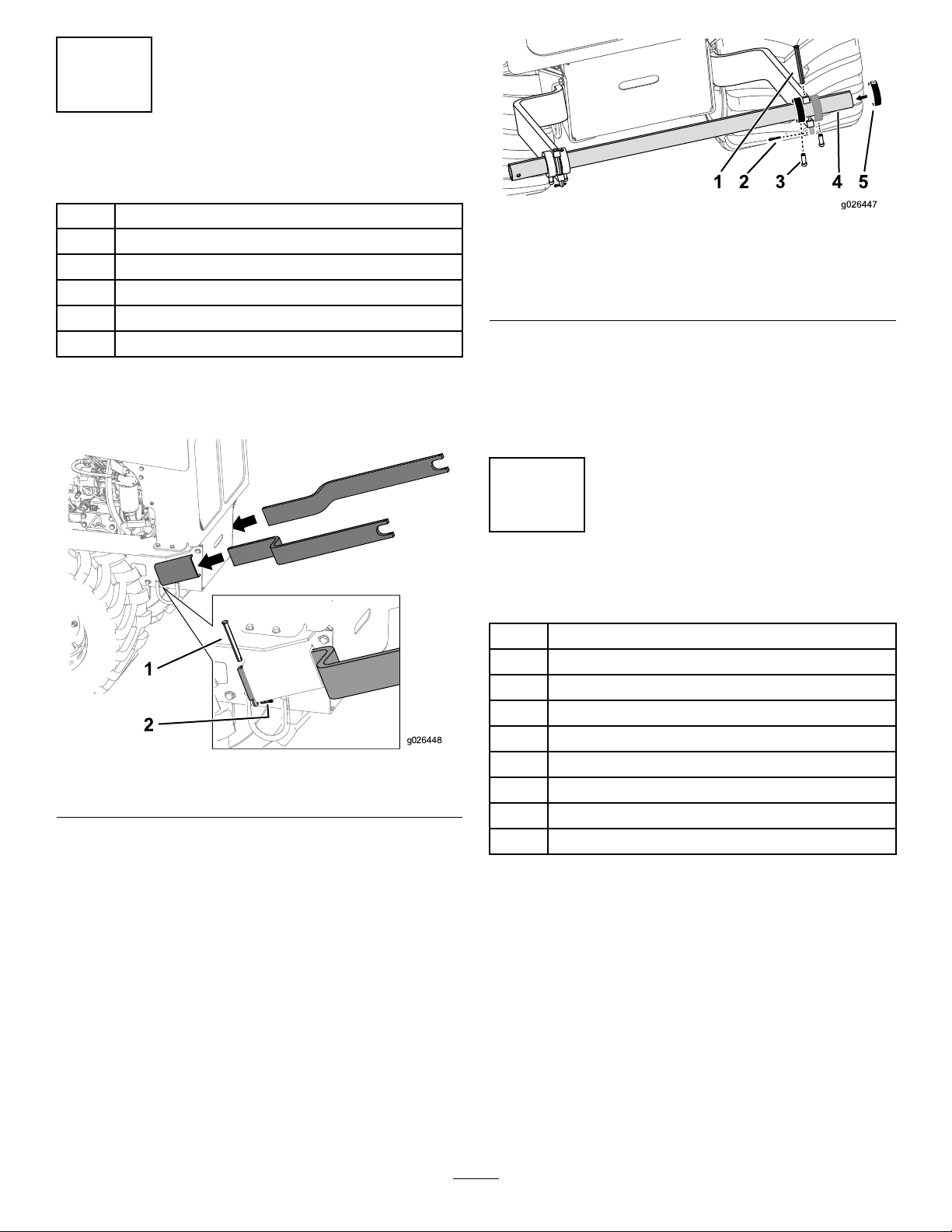
InstallingtheCableGuides
Partsneededforthisprocedure:
1
ROPS-cable-guidebracket
1
U-bolt(4inches)
2
Locknut(3/8inch)
4
Spacers
1
Hood-cable-guidebracket(model25400only)
2
Nut(5/16)(model25400only)
2
Bolt(5/16x3/4inch)(model25400only)
1
Benthood-cable-guidebracket(model25403only)
2
Bolt(5/16x1inch)(model25403only)
InstallingtheCableGuidesforthe
ProSneak360
1.Raisethehoodofthemachineandsupportthehood
withtheproprod.
2.Mountthehood-cable-guidebracketontheoutside
ofthehoodandplacethe2bolts(5/16x3/4inch)
throughtheholesonthebracketandthemachine,and
securethebracketwiththe2nuts(5/16inch)onthe
insideofthehood(Figure3).
2
Page 3

1
2
3
g022154
Figure3
3 4
1
2
3
g026715
g026714
1.Bolt(5/16x3/4inch)3.Nut(5/16inch)
2.Hood-cable-guidebracket
InstallingtheCableGuidesforthe
ProSneak365
1.Opentherightorleftsidepanelsofthemachinehood.
2.Removetheexistingboltsandnutsbetweenthefront
noseconeandthecenterstrip.
Note:Donotdiscardthenuts.
3.Securethebentcable-guidebracketbetweenthecenter
stripandthefrontnoseconeusing2bolts(5/16x1
inch)andthe2nutspreviouslyremoved(Figure5).
3.SecuretheROPS-cable-guidebracketusing1U-bolt(4
inches),4spacers,and2locknuts(3/8inch)asshown
inFigure6.
1.Nuts3.Bolts
2.Bracket
Figure5
4.SecuretheROPS-cable-guidebracketusing1U-bolt(4
inches),2spacers,and2locknuts(3/8inch)asshown
inFigure6.
Figure4
1.ROPS-cable-guide
bracket
2.U-bolt
3.Spacers
4.Locknut(3/8inch)
1.Locknut
2.Spacer
Figure6
3.ROPS-cable-guide
bracket
4.U-bolt
3
Page 4

Operation
1
g023496
Important:Determinethelocationofunderground
linesbeforestarting.
UsingtheReelCarrier
1.Removethechutegateandinsertthecableortubing.
2.Installthechutegate.
Note:Checkthechutelinksforwearandfreedomof
movement.
3.Lowerthebladetothegroundandanchortheendof
thecableasnecessary.
4.Removetheplowsinglockingpinandinsertitinto
theholebytheseat.
5.Slowlylowerthebladeintothegroundandstart
movingthemachineforwardslowly,usingthe
creep-controllever.
Anoptionalstartingmethodisasfollows:
A.Digaholetothebuildingandlowerthebladeto
fulldepth.
MakingaServiceConnection
1.Digaholetothedepththecableisbeinglaidandno
widerthan0.6m(2ft).
2.Asyoupassovertheholewiththemachine,stopthe
plowvibrationandinserttheplow-swinglock(Figure
7).
B.Threadthecableortubingintothechuteand
pushitthroughthewall.
C.Securethecableendandslowlymovethemachine
forward.
6.Starttheplowvibrationafterthebladeentersthe
ground.
Note:Whenusingabladewithchutelinks,besure
thatthechutelinksarehorizontalasthebladeenters
theground.Youwilldamagethecableandchuteifthe
bladeisforcedintothegroundtoofast.Iftheground
isveryhard,youcanpowerthebladedown.
7.Increasethecreepspeed.
Note:Donotallowtirestoslipbecausethiswilllower
theefciencyofthemachine.
8.Ifyouencounteranundergroundobstacle,increase
vibrationspeedandmaintainslightforwardpressure
withthemachine.
Note:Thisletstheobstaclemovetoonesideor
allowstheplowbladetomovearoundtheobstacle.Be
surethattheplowswinglockisremoved(Figure7).
Figure7
1.Plow-swinglock
3.Plowintotheholeandstopthemachine.
4.Connectthecables,makealoopintheconnected
cablesandsecureit.
5.Movethemachineforwardwhilepushingthecable
downthechute.
6.Removetheplowsinglockingpinandinsertitinto
theholebytheseat.
7.Starttheplowvibrationafterthebladeentersthe
ground.
Note:Whenyouuseachuteblade,checkitforwear
andfreedomofmovementdaily.Replacethelinks
beforetheywearout.
4
 Loading...