

Page 1
FormNo.3377-939RevB
HydraBorer
ProSneak360VibratoryPlow
ModelNo.25418—SerialNo.313000001andUp
ModelNo.25418E—SerialNo.313000001andUp
Operator'sManual
Safety
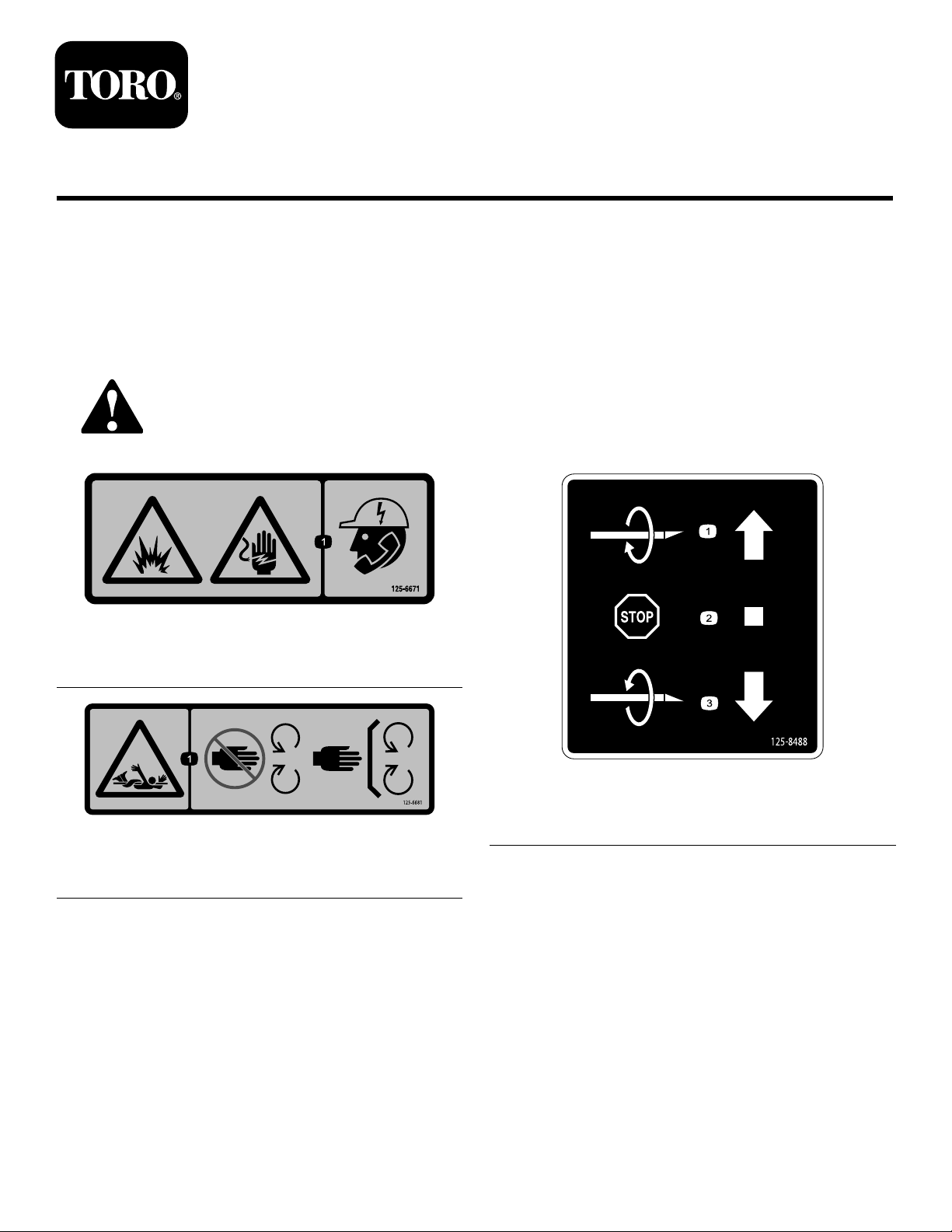
SafetyandInstructional
Decals
Safetydecalsandinstructionsareeasilyvisibletotheoperatorandarelocatednearanyareaofpotential
danger.Replaceanydecalthatisdamagedorlost.
125-6671
1.Explosionhazard;electricshockhazard—calllocalutilities
beforedigging.
125–6681
1.Entanglementhazard—keepawayfrommovingparts;keep
allguardsinplace.
125–8488
1.Turnclockwise3.Turncounterclockwise
2.Stoprotation
©2013—TheToro®Company
8111LyndaleAvenueSouth
Bloomington,MN55420
Registeratwww.Toro.com.
OriginalInstructions(EN)
PrintedintheUSA
AllRightsReserved
*3377-939*B
Page 2

Setup
LooseParts
Usethechartbelowtoverifythatallpartshavebeenshipped.
ProcedureDescription
1
2
3
Motor1
Adapter1
Retaineradapter1
Lockwasher1
Bolt(1/2x1-1/4inches)
90-degree,elbowtting
Hose,114.3cm(45inches)
Bracket1
Bolt(1/2x1-3/4inch)
Flatwasher(1/2inch)
Locknut(1/2inch)
Jointassembly1
Nut(3/8inch)
Bolt(3/8x2-1/2inch)
Bracket1
Controlvalve
90-degree,elbowtting
45-degree,elbowtting
Straighttting
Bolt(3/8x1inch)
Flatwasher(3/8inch)
Nut(3/8inch)
Bolt(5/16x2-1/2inch)
Bolt(5/16x2-1/4inch)
Flatwasher(0.344inch)
Locknut(5/16inch)
Clevispin
Cotterpin
Controllever
Linkassembly1
Snapclip
Hose,114.3cm(45inches)
Hose,91.44cm(36inches)
Hose,37.44cm(14.74inches)
Hoseconnector1
Qty.
Use
1
2
2
8
8
8
1
1
1
1
2
1
2
4
2
1
1
2
2
1
1
1
1
2
1
1
InstalltheHydraBorerMotor
Installthecontrolvalveandhandle.
Installthehoses.
2
Page 3
1
1
2
3
4
g021919
5
g021920
g021921
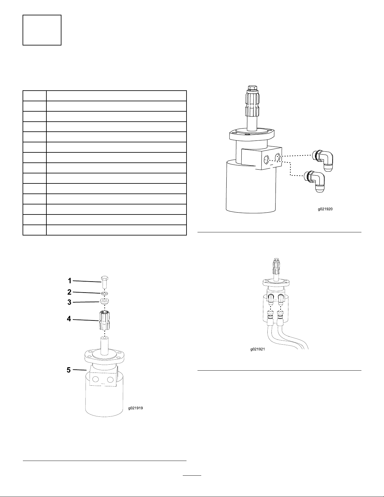
InstallingtheHydraBorer Motor
Partsneededforthisprocedure:
1Motor
1Adapter
1Retaineradapter
1Lockwasher
1
Bolt(1/2x1-1/4inches)
2
90-degree,elbowtting
2
Hose,114.3cm(45inches)
1Bracket
8
Bolt(1/2x1-3/4inch)
8
Flatwasher(1/2inch)
8
Locknut(1/2inch)
1Jointassembly
1
Nut(3/8inch)
1
Bolt(3/8x2-1/2inch)
2.Puttheretaineradapterontheadapter.
3.Placethewasherontheboltandapplythread-locking
adhesivetothebolt.
4.Securethebolttotheadapters;torqueto160to165
N-m(118to122ft-lb).
5.Install2ofthe90-degree,elbowttingsintotheports
onthemotor(
Figure2).
Figure2
6.Attachthe114.3cm(45inch)hosestotheelbow
Procedure
ttingsonthemotor(Figure3).
1.Greasetheshaftofthemotorandplacetheadapter
ontothemotor(Figure1).
Figure3
Figure1
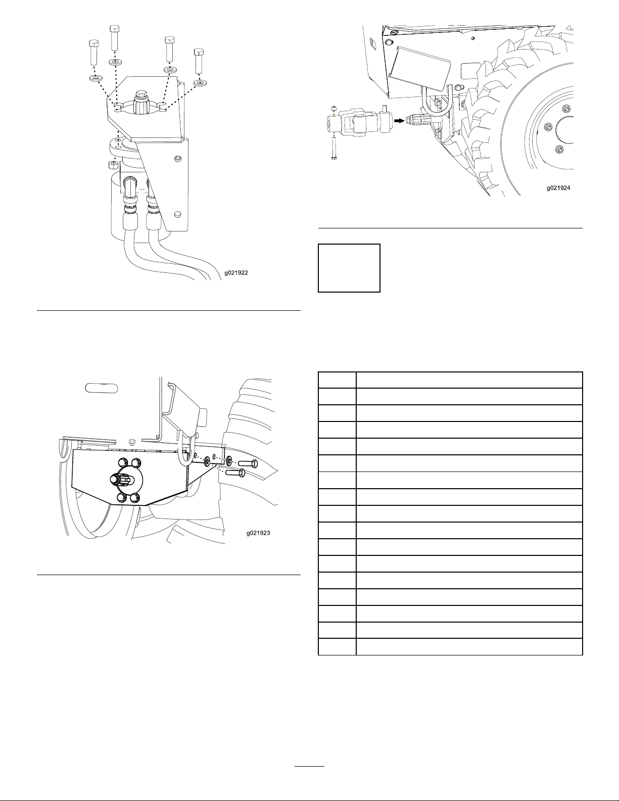
7.Securethebrackettothemotorusingthe4bolts(1/2
x13/4inch),the4atwashers(1/2inch),andthe4
locknuts(1/2inch)(Figure4);torqueto140to144
N-m(100to110ft-lb).
1.Bolt(1/2x1-1/4inch)
2.Lockwasher5.Motor
3.Retaineradapter
4.Adapter
3
Page 4
g021922
g021923
g021924
Figure6
Figure4
8.Securethemotorassemblytothemachineusing2
bolts(1/2x1-3/4inch),2atwashers(1/2inch),and
2locknuts(1/2inch);torqueto142N-m(105ft-lb).
(
Figure5).
Figure5
9.Installthejointassemblytothemotorassembly.Secure
withthebolt(3/8inch)andthenut(3/8x2-1/2inch)
(Figure6);torqueto55to63N-m(40to45ft-lb).
2
InstallingtheControlValve andHandle
Partsneededforthisprocedure:
1Bracket
1
Controlvalve
1
90-degree,elbowtting
2
45-degree,elbowtting
1
Straighttting
2
Bolt(3/8x1inch)
4
Flatwasher(3/8inch)
2
Nut(3/8inch)
1
Bolt(5/16x2-1/2inch)
1
Bolt(5/16x2-1/4inch)
2
Flatwasher(0.344inch)
2
Locknut(5/16inch)
1
Clevispin
1
Cotterpin
1
Controllever
1Linkassembly
1
Snapclip
4
Page 5

Procedure
g021925
1
2
3
g021926
5
2
3
4
g021927
1
6
1
2
3
g021928
4
1.InstallthettingsasshowninFigure7.
Figure7
2.Installthebracketandsecurewiththe2nuts(3/8
inch),the2washers(3/8inch),andthe2bolts(3/8
inch)(Figure8);torqueto38to43N-m(28to32ft-lb).
Figure9
Figure8
1.Nut(3/8inch)3.Bolt(3/8inch)
2.Flatwasher(3/8inch)
3.Installthecontrolvalveontothebracketandsecure
withthe2bolts(5/16x2-1/4inchand5/16x2-1/2
inch),the2atwashers(0.344inch)andthe2locknuts
(5/16inch)(Figure9);torqueto32to35N-m(280
to310in-lb).
1.Bolt(2-1/4inch)
2.Bolt(2-1/2inch)5.Controlvalve
3.Washer(0.344inch)6.Locknut(5/16inch)
4.Bracket
4.Placethehydra-borer-controlleverbetweentheguide
onthebracketattachedtothemachinesothatthe
holeslineup.Securethecontrolleverwiththelink
assemblyandsnapclip(Figure10).
1.Cotterpin
2.Clevispin4.Snapclip
5.Securetheupperholeofthecontrolleverwiththe
clevispinandthecotterpin(Figure10).
5
Figure10
3.Linkassembly
Page 6

3
1
2
3
4
3
g0 219 79
2
g021980
1
2
3
4
2
g021981
1
3
InstallingtheHoses
Partsneededforthisprocedure:
2
Hose,114.3cm(45inches)
1
Hose,91.44cm(36inches)
1
Hose,37.44cm(14.74inches)
1Hoseconnector
InstallingtheHosesonallMachines
Figure12
1.PortAonthemotor3.PortAonthe
hydra-borer-controlvalve
2.PortBonthemotor4.PortBonthe
hydra-borer-controlvalve
2.Routetheother114.3cm(45inch)hosefromportB
onthemotortoportBonthehydra-borer-control
valve(Figure11andFigure12).
InstallingtheHosesonaMachine
withoutaTrencherAttached
Figure11
ControlValveViews
1.45-degreetting(B
port/45-inchhosefrom
Motor)
2.90-degreetting(HoseB
(14.74-inchhose)toPlow
Valve)
1.Routea114.3cm(45inch)hosefromportAonthe
motortoportAonthehydra-borer-controlvalve
(
Figure12).
3.45-degreetting(A
Port/45-inchhosefrom
Motor)
4.Straighttting(Hose
C/36-inchhose)
Note:Routethehosesundertheframe.
Usethisprocedureifyouhaveamachinethatdoesnothave
atrencherattached.Ifyouhaveamachinehastrencher
attached,gotoInstallingtheHosesonaMachinewitha
TrencherAttached(page7).
Figure13
Currenthoserouting
1.HydraulicPump3.Plow-controlvalve
2.HoseA(currentlyinstalled
onthemachine)
6
Page 7

1.ConnecthoseB(14.74inches)tothe90-degreetting
1
2
4
g021983
3
5
1
g021984
3
2
1
2
4
g021983
3
5
onthecontrolvalve(Figure11andFigure14).
Figure14
1.Hoseconnector4.Plow-controlvalve
2.Hydra-borer-controlvalve
3.HoseA
5.HoseB(14.74inches)
2.DisconnecthoseAfromthehydraulicpump,addthe
hoseconnector,andconnecthoseBtotheotherend
oftheconnector(Figure13andFigure14).
InstallingtheHosesonaMachinewith
aTrencherAttached
Usethisprocedureifyouhaveamachinethathasatrencher
attached.Ifyouhaveamachinethatdoesnothaveatrencher
attached,gotoInstallingtheHosesonaMachinewithouta
TrencherAttached(page6).
Figure16
Currenthoseroutingonamachinewithatrencherinstalled.
3.ConnecthoseC(36inches)tothestraightttingon
thecontrolvalve(Figure11andFigure15).
1.HoseE(trencherhose)
2.Hydraulicpump
3.HoseA(sameashoseA
inpreviousgures)
4.Plow-controlvalve
5.HoseD(trencherhose)
6.Hoseconnector
1.DisconnecthoseAfromhoseD ,leavingthehose
connectorattachedtohoseA(Figure16).
2.ConnecthoseBtothe90-degreettingonthe
hydra-borer-controlvalve(Figure11andFigure17).
Figure15
1.Hydra-borer-controlvalve
2.Hydraulicpump
4.ConnecthoseCtothehydraulicpump(wherehoseA
waspreviouslyattached).
3.HoseC(36inches)
Figure17
1.Hoseconnector4.Plow-controlvalve
2.Hydra-borer-controlvalve
3.HoseA
5.HoseB(14.74inches)
3.ConnecthoseBtothehoseconnectorattachedto
hoseA.
7
Page 8

4.ConnecthoseCtothestraightttingonthe
1
2
3
g021985
4
5
hydra-borer-controlvalve(Figure11andFigure18).
Figure18
1.HoseC(36inches)
2.Hydra-borer-controlvalve5.Trencher-controlvalve
3.Hoseconnector
5.ConnectthehoseconnectortohoseDandconnectto
hoseCtothehoseconnector(
4.HoseD
Figure18).
Operation
Figure19
1.Entrancetrench3.Exittrench
2.Sidewalk
BoringtheHole
Important:Boringisatwopersonoperation.Donot
attempttoperformthisoperationbyyourself.
1.Positionthemachinewiththedriveheadatthe
beginningofthetrenchandlowerittotheappropriate
depth.
2.Stoptheengineandwaitforallmovingpartstostop.
3.Connectarodandboringbitontothedrivehead.
4.Connecttherodguidetooltotherodjustbehindthe
boringbit(Figure20).
BoringaHole
DiggingtheTrenches
Beforedrillingunderawalkordriveway,youmustmakean
entranceandanexittrenchoneithersideofthedrillingarea.
Bothtrenchesmustbeatleast15.24cm(6inches)wideand
45.72cm(18inchesdeep).Theentrancetrenchmustbeat
least213.36cm(7feet)longandtheexittrench91.44to
182.88cm(3to6feet)long.Theentrancetrenchshouldbe
perpendiculartothewalkordrivewayandtheexittrench
shouldbeparalleltothewalkordriveway.Theexittrench
shouldbecenteredacrossfromtheentrancetrench(Figure
19).
Figure20
1.Sidewalkordriveway
2.Entrancetrench5.Rodguidetool
3.Boringbit
5.Withthepersonguidingtheboringbitpositionedto
therightofthetrench(Figure20),starttheengine,
movethepumpselectorvalvetoslow ,positionthe
throttletowithinthemiddleoftheRPMrange,and
pushthehydra-borer-controlleverforwardtostartthe
forwardrotationoftheboringbit.
6.Slowlymovethemachineforward,whiletheperson
withtherodguidetoolguidestheboringbitintothe
soil(Figure20).
4.Rod
8
Page 9

7.Oncetheentiredrillbitisinthesoil,pushthecontrol
leverintoneutral.
8.Stoptheengineandwaitforallmovingpartstostop.
9.Checkthegradeoftherod.
Iftherodisnotwithinthegradetolerancesforthejob
beingperformed,starttheengine,anddrivebackward
topulltheboringbitoutofthesoil,thenrepeatsteps
through9,makingadjustmentstocorrectthegrade.
10.Removetherodguidetool.
11.Starttheengineandpullthecontrolleverrearwardto
starttheboringbit.
5
12.Slowlymovethemachineforwardastheboringbit
digsintothesoil.
Important:Donotdrivetoofast,forcingthebit
intothesoil.Allowthebittoprogressatitsown
rate.Donotpushorpullthebitthroughthesoil
whenthedriveheadisnotturning.
13.Whenabout15cm(6inches)ofrodareleftshowingin
theentrancetrenchorwhentheboringbitcompletely
entersandboresintothefarsideoftheexittrench,
stopthemachine,pushthecontrolleverintoneutral,
andstoptheengine.
14.Iftheboringbithasnotyetenteredtheexittrench,
completethefollowing:
A.Detachtherodfromthedrivehead.
B.Starttheengineandbackuptotheendofthe
entrancetrench.
C.Stopengineandwaitforallmovingpartstostop.
D.Connectanotherrodandrepeatsteps
11through
14.
ReamingtheHole
1.Withashovel,carefullydigaroundtheboringbit
clearingitofsoiluntilitcanberemoved(Figure21).
Figure21
1.Sidewalkordriveway
2.Exittrench
3.Shoveldugareaaround
bit
4.Reamer
5.Swivel
2.Removetheboringbitandattachthereamer(Figure
21).
3.Attachthecableorpipingbeinginstalledtotheswivel
ontheendofthereamer(Figure21).
4.Starttheengineandpullthecontrolleverrearwardto
startthereamer.
5.Slowlymovethemachinerearwardasthereamerdigs
intothesoil.
Important:Donotdrivetoofast,forcingthe
reamerintothesoil.Allowthereamertoprogress
atitsownrate.Neverpushorpullthereamer
throughthesoilwhenthedriveheadisnotturning.
6.Whenarodcouplingisabout15cm(6inches)intothe
entrancetrenchorwhenthereamercompletelyenters
thetrenchwithabout15cm(6inches)ofthecableor
piping,stopthemachine,pullthecontrolleverinto
neutral,andstoptheengine.
7.Ifthereamerhasnotyetenteredtheexittrench,
completethefollowing:
A.Detachtherodfromthedriveheadandrodstill
inthesoil.
B.Starttheengineandmovetothefrontofthe
entrancetrench.
C.Stoptheengineandwaitforallmovingpartsto
stop.
D.Connectthedriveheadtotherodshaftinthesoil.
E.Repeatsteps
4through7.
8.Withthereamerandcable/pipingintheentrance
trench,removethecableorpipingfromthereamer.
9
Page 10

Storage
1.Beforelongtermstorage,washtheattachmentwith
milddetergentandwatertoremovedirtandgrime.
2.Checktheconditionofthehydraulichoses.Replace
anydamagedhoses.
3.Ensurethatallhydrauliccouplersareconnected
togethertopreventcontaminationofthehydraulic
system.
4.Checkandtightenallbolts,nuts,andscrews.Repairor
replaceanydamagedorwornpart.
5.Paintallscratchedorbaremetalsurfaces.Paintis
availablefromyourAuthorizedServiceDealer.
6.Storetheattachmentinaclean,drygarageorstorage
area.Coverittoprotectitandkeepitclean.
10
Page 11

Troubleshooting
Problem
Theboredriveheadwillnotrotate.
PossibleCauseCorrectiveAction
1.Thehydrauliccouplerisnotcompletely
connected.
2.Ahydrauliccouplerisdamaged.
3.Thereisanobstructioninahydraulic
hose.
4.Ahydraulichoseiskinked.4.Replacethekinkedhose.
5.Theauxiliaryvalveonthemachineis
notopening.
6.Ahydraulicmotorisdamagedorworn.6.Replaceorrepairthemotor.
1.Checkandtightenallcouplers.
2.Checkthecouplersandreplaceany
thataredamaged.
3.Findandremovetheobstruction.
5.Repairthevalve.
11
Page 12

TheT oroUndergroundWarranty
ALimitedWarranty
AstecBrandProduct
Soldafter
November1,2012
ConditionsandProductsCovered
TheT oroCompanyanditsafliate,T oroWarrantyCompany ,pursuant
toanagreementbetweenthem,jointlywarrantyourT oroUnderground
product(“Product”)tobefreefromdefectsinmaterialsorworkmanship.
Whereawarrantableconditionexists,wewillrepairtheProduct
atnocosttoyouincludingdiagnostics,labor,andparts.
ThefollowingwarrantyappliesfromthedatetheProductisdeliveredto
theoriginalretailpurchaserorrentalowner.
ProductsWarrantyPeriod
RT600,RT800,RT1000,RT1200,
DD2024,andDD4045
AllOtherEnginePoweredBase
UnitsandFluidMixers
AllSerializedAttachments
RockHammer6months
Engines
2yearsor1500operatinghours,
whicheveroccursrst
1yearor1000operatinghours,
whicheveroccursrst
1year
Throughenginemanufacturers:
2yearsor2000operatinghours,
whicheveroccursrst
InstructionsforObtainingWarrantyService
YouareresponsiblefornotifyingtheUndergroundDealerfromwhomyou
purchasedtheProductassoonasyoubelieveawarrantablecondition
exists.IfyouneedhelplocatingaUndergroundDealer,orifyouhave
questionsregardingyourwarrantyrightsorresponsibilities,youmay
contactusat:
ToroCustomerCare
ToroWarrantyCompany
811 1LyndaleAvenueSouth
Bloomington,MN55420-1196
TollFreeat855-493-0088(U.S.Customers)
1-952-948-4318(InternationalCustomers)
OwnerResponsibilities
AstheProductowner,youareresponsibleforrequiredmaintenance
andadjustmentsstatedinyourOperator'sManual.Failuretoperform
requiredmaintenanceandadjustmentscanbegroundsfordisallowinga
warrantyclaim.
ItemsandConditionsNotCovered
Notallproductfailuresormalfunctionsthatoccurduringthewarranty
periodaredefectsinmaterialsorworkmanship.Thiswarrantydoesnot
coverthefollowing:
•Productfailureswhichresultfromtheuseofnon-T ororeplacement
parts,orfrominstallationanduseofadd-on,ormodiednon-T oro
brandedaccessoriesandproducts.Aseparatewarrantymaybe
providedbythemanufactureroftheseitems.
•Productfailureswhichresultfromfailuretoperformrecommended
maintenanceand/oradjustments.Failuretoproperlymaintainyour
ToroproductpertheRecommendedMaintenancelistedinthe
Operator’sManualcanresultinclaimsforwarrantybeingdenied.
•ProductfailureswhichresultfromoperatingtheProductinan
abusive,negligent,orrecklessmanner.
•Partssubjecttoconsumptionthroughuseunlessfoundtobe
defective.Examplesofpartswhichareconsumed,orusedup,during
normalProductoperationinclude,butarenotlimitedto:brakes,
lters,lights,bulbs,belts,tracksortires,diggingteeth,diggingbooms,
digging,drive,ortrackchains,trackpads,drivesprockets,idlers,
rollers,blades,cuttingedges,orothergroundengagingcomponents.
•Failurescausedbyoutsideinuence.Conditionsconsideredtobe
outsideinuenceinclude,butarenotlimitedto,weather,storage
practices,contamination,useofunapprovedfuels,coolants,
lubricants,additives,water ,orchemicals,etc.
•Failureorperformanceissuesduetotheuseoffuels(e.g.gasoline,
diesel,orbiodiesel)thatdonotconformtotheirrespectiveindustry
standards.
•Normalnoise,vibration,wearandtear,anddeterioration.
•Normal“wearandtear”includes,butisnotlimitedto,damagetoseats
duetowearorabrasion,wornpaintedsurfaces,scratcheddecals,etc.
•Haulingexpenses,traveltime,mileage,orovertimeassociatedwith
transportingproducttotheauthorizedT orodealer.
Parts
Partsscheduledforreplacementasrequiredmaintenanceinthe
Operator’sManual,arewarrantedfortheperiodoftimeuptothescheduled
replacementtimeforthatpart.Partsreplacedunderthiswarrantyare
coveredforthedurationoftheoriginalproductwarrantyandbecomethe
propertyofToro.Torowillmakethenaldecisionwhethertorepairany
existingpartorassemblyorreplaceit.T oromayuseremanufactured
partsforwarrantyrepairs.
MaintenanceisatOwner’sExpense
Enginetune-up,lubrication,cleaningandpolishing,replacementoflters,
coolant,andcompletingrecommendedmaintenancearesomeofthe
normalservicesT oroproductsrequirethatareattheowner’sexpense.
GeneralConditions
RepairbyanAuthorizedT oroUndergroundDealerisyoursoleremedy
underthiswarranty.
NeitherTheToroCompanynorToroWarrantyCompanyisliablefor
indirect,incidentalorconsequentialdamagesinconnectionwiththe
useoftheT oroProductscoveredbythiswarranty ,includingany
costorexpenseofprovidingsubstituteequipmentorserviceduring
reasonableperiodsofmalfunctionornon-usependingcompletion
ofrepairsunderthiswarranty .ExceptfortheEmissionswarranty
referencedbelow,ifapplicable,thereisnootherexpresswarranty .
Allimpliedwarrantiesofmerchantabilityandtnessforuseare
limitedtothedurationofthisexpresswarranty.
Somestatesdonotallowexclusionsofincidentalorconsequential
damages,orlimitationsonhowlonganimpliedwarrantylasts,sothe
aboveexclusionsandlimitationsmaynotapplytoyou.Thiswarranty
givesyouspeciclegalrights,andyoumayalsohaveotherrightswhich
varyfromstatetostate.
Noteregardingenginewarranty:
TheEmissionsControlSystemonyourProductmaybecoveredby
aseparatewarrantymeetingrequirementsestablishedbytheU.S.
EnvironmentalProtectionAgency(EPA)and/ortheCaliforniaAir
ResourcesBoard(CARB).Thehourlimitationssetforthabovedonot
applytotheEmissionsControlSystemWarranty .RefertotheEngine
EmissionControlWarrantyStatementsuppliedwithyourproductor
containedintheenginemanufacturer’sdocumentationfordetails.
CountriesOtherthantheUnitedStatesorCanada
CustomerswhohavepurchasedT oroproductsexportedfromtheUnitedStatesorCanadashouldcontacttheirToroDistributor(Dealer)toobtain
guaranteepoliciesforyourcountry,province,orstate.IfforanyreasonyouaredissatisedwithyourUndergroundDealer’sserviceorhavedifculty
obtainingguaranteeinformation,contacttheT oroimporter.
AustralianConsumerLaw:AustraliancustomerswillnddetailsrelatingtotheAustralianConsumerLaweitherinsidetheboxoratyourlocalT oro
Dealer.
374-0291RevA
 Loading...