

Page 1
BeaconLightKit
RT600orRT1200Trencher
ModelNo.25415
ModelNo.25415E
FormNo.3394-714RevA
InstallationInstructions
Note:Determinetheleftandrightsidesofthemachine
fromthenormaloperatingposition.
Safety
WARNING
CALIFORNIA
Proposition65Warning
Thisproductcontainsachemicalorchemicals
knowntotheStateofCaliforniatocausecancer,
birthdefects,orreproductiveharm.
Installation
LooseParts
SafetyandInstructional
Decals
Safetydecalsandinstructionsareeasily
visibletotheoperatorandarelocatednear
anyareaofpotentialdanger.Replaceany
decalthatisdamagedorlost.
120–0771
1.BeaconLight
Usethechartbelowtoverifythatallpartshavebeenshipped.
ProcedureDescription
1
2
3
4
5
Nopartsrequired
Decal1
BeaconLight1
BeaconLightMount(RT600only)
Bolt3/8x6inches(RT600only)
Washerhardened(RT600only)
Flangenut(RT600only)
WiringHarness1
Switch
SwitchBoot
Qty.
Use
–
1
2
2
2
1
1
Preparingthemachine.
Locatingmountingholesanddecal
placement.
Mountingthebeaconlight.
Connectingthewiringharnesstothe
machine.
ConnectingOn/Offswitchandrouting
thewiringharnesstobeaconlight.
©2015—TheT oro®Company
8111LyndaleAvenueSouth
Bloomington,MN55420
Registeratwww.T oro.com.
OriginalInstructions(EN)
PrintedintheUSA
AllRightsReserved
*3394-714*A
Page 2
1
PreparingtheMachine
NoPartsRequired
Procedure
1.Movethemachinetoalevelsurface.
2.Settheparkingbrake,shutofftheengine,andremove
thekeyfromthekeyswitch.
3.Removetherightsidepanel;refertotheOperator’s
Manual.
4.Disconnectthebattery;refertotheOperator’ sManual.
2
LocatingMountingHolesand DecalPlacement
Partsneededforthisprocedure:
1Decal
Procedure
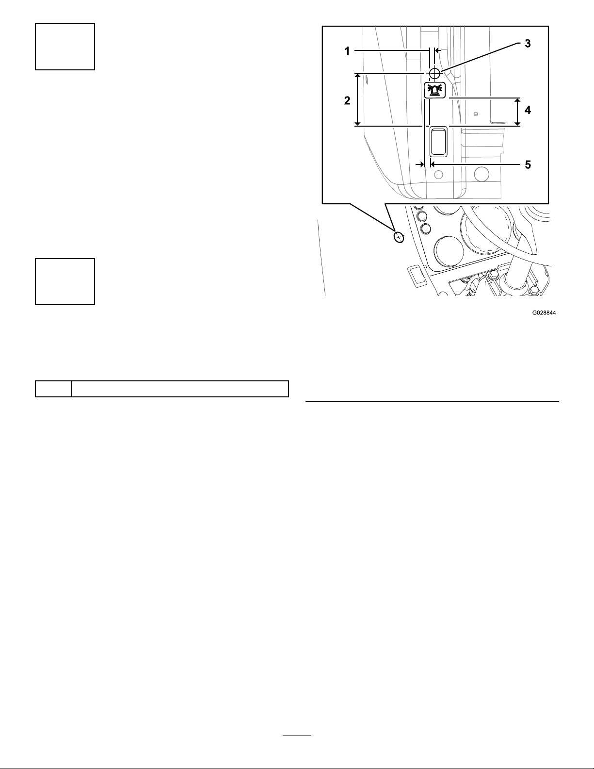
1.Locateandmarktheswitchholelocationforyour
specicmodel(Figure1orFigure2).
2.Drilltheindicatedholesizeatthelocationyoumarked.
3.Locatethepositionandapplythebeaconlightdecal
foryourspecicmodel(Figure1orFigure2).
Note:Stopdrillingimmediatelyaftercompletely
penetratingthesurface.
Figure1
RT600
1.6mm(0.25inch)4.35mm(1.375inch)
2.66mm(2.5inch)5.6mm(0.25inch)
3.13mm(0.5inchDiameter)
2
Page 3
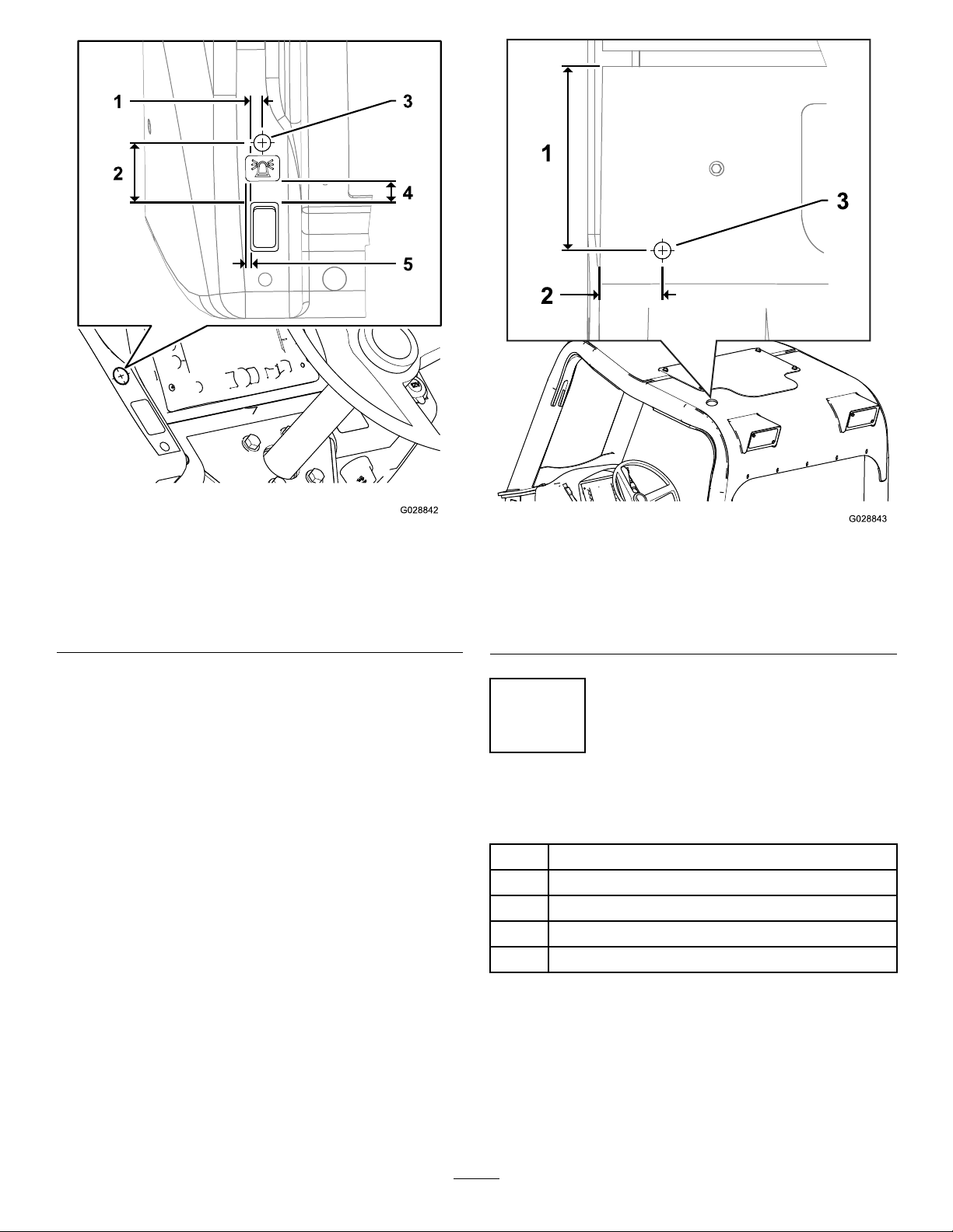
Figure2
RT1200
1.9mm(0.35inch)4.16mm(0.625inch)
2.44mm(1.75inch)5.4mm(0.15inch)
3.13mm(0.5inch)
1.Locateandmarkthebeaconholelocation(Figure3).
2.Drilltheindicatedholesizeatthemarkedlocation.
Figure3
RT1200
1.318mm(12.5inch)3.22mm(0.875inch
diameter)
2.127mm(5inch)
Note:Stopdrillingimmediatelyaftercompletely
penetratingthesurface.
3
MountingtheBeaconLight
Partsneededforthisprocedure:
1BeaconLight
1
BeaconLightMount(RT600only)
2
Bolt3/8x6inches(RT600only)
2
Washerhardened(RT600only)
2
Flangenut(RT600only)
MountingthebeaconlighttotheRT600
1.Usetheincludedhardwaretomountthebeaconlight
mountingbrackettoptheROPS(Figure4).
2.Removethemountinghardwarefromthethreaded
shaftonthebeaconlightandinserttheshaftintothe
beaconlightmounthole(Figure4).
3
Page 4

3.Installthemountinghardwarebackontothethreaded
shaftandtightenuntilsecure.Donotover-tightenthe
retaininghardware.
Figure5
RT1200
Figure4
RT600
1.Beaconlight4.Washerhardened
2.Beaconlightmounting
bracket
3.Flangenut(3/8inch)
5.Bolt(3/8x6inches)
Mountingthebeaconlighttothe
RT1200
1.Removethemountinghardwarefromthethreaded
shaftonthebeaconlight.
2.Placetheshaftofthebeaconlightthroughthe
mountingholeinthecanopy(Figure5).
3.Installthemountinghardwarebackontothethreaded
shaftandtightenuntilsecure.Donotover-tightenthe
retaininghardware.
1.Beaconlightthreaded
shaft
2.Beaconlightmounting
hole
4
ConnectingtheWiring HarnesstotheMachine
Partsneededforthisprocedure:
1WiringHarness
Procedure
1.Behindthebattery-disconnectswitchontherightside
ofthemachine,removeoneinsulatorlug,nut,and
lock-washerfromtheterminalfurthestawayfromthe
engine(Figure6orFigure7).
2.Usingthehardwareremoved,attachoneringterminal
ofthewireharnesstotheterminalfurthestawayfrom
theengine(Figure6orFigure7).
4
Page 5

Figure6
RT600
1.InsulatorLug4.Ring-terminal
2.Nut5.Positiveterminal
3.Lock-washer6.Batery-disconnectswitch
Figure7
RT1200
1.InsulatorLug4.Ring-terminal
2.Nut5.Positiveterminal
3.Lock-washer6.Batery-disconnectswitch
3.Removetheboltattachedtotheengineground.(Figure
8orFigure9).
4.Usingtheboltyouremoved,attachtheotherring
terminaltotheengineground(Figure8orFigure9).
5
Page 6

Figure8
RT600
1.Bolt3.Engineground
2.Ringterminal
5
ConnectingOn/OffSwitchand RoutingtheWiringHarnessto BeaconLight
Partsneededforthisprocedure:
1
Switch
1
SwitchBoot
Procedure
1.Ifequipped,removethepanelbeneaththedashboard
(Figure10).
Figure9
RT1200
1.Battery-disconnectswitch3.Engineground
2.Bolt4.Ringterminal
Figure10
1.Bolt2.Kickerpanel
2.Routethewiringharnesstotheoperatorareaand
underneaththedashboard(Figure12orFigure13).
3.Removethemountinghardwarefromthethreaded
shaftoftheswitch,androutetheswitchtothe
undersideofthemountinghole.
4.Installthemountinghardwarebackontothethreaded
shaftandtightenuntilsecure.Donotover-tighten
retainingthehardware.
5.Installtheswitchbootoverthetoggle.
6
Page 7

Figure11
RT1200Shown
1.SwitchBoot2.BeaconLightSwitch
6.Routetheremainderofthewiringharnessunderneath
theoperatorareaandconnectittothebeaconlight
(Figure12orFigure13).Ifnecessary,removethefoot
plate;refertotheOperator’ sManual.
7.Usetheprovidedmagneticcabletiemountsand
additionalcabletieswhererequiretoproperlysecure
thewiringharness.
Figure12
RT600
1.RecommendedwiringharnessroutefortheRT600.
Figure13
RT1200
1.RecommendedwiringharnessroutefortheRT1200.
8.Installanypartsyouremoved,reconnectthebattery,
androtatethebattery-disconnectswitchtotheOn
position,ifequipped.
7
Page 8

Operation
UsingtheBeaconLight
1.ToggletheswitchfromtheOffpositiontoturnthe
beaconlighton.
2.ReturntheswitchtotheOffpositiontoturnthe
beaconlightoff.
Note:Rotatethebeaconlightswitch180degreestoachieve
thedesireOnorOffposition.
8
 Loading...