

Page 1
HornKit
RT600orRT1200Trencher
ModelNo.25409
ModelNo.25409E
Note:Determinetheleftandrightsidesofthemachinefromthenormaloperatingposition.
Safety
WARNING
CALIFORNIA
Proposition65W arning
ThisproductcontainsachemicalorchemicalsknowntotheStateofCaliforniato
causecancer,birthdefects,orreproductiveharm.
FormNo.3394-706RevB
InstallationInstructions
SafetyandInstructionalDecals
Safetydecalsandinstructionsareeasilyvisibletotheoperatorandarelocatednearanyareaofpotential
danger.Replaceanydecalthatisdamagedorlost.
104-6957
1.Horn
Installation
LooseParts
Usethechartbelowtoverifythatallpartshavebeenshipped.
ProcedureDescription
Qty.
Use
1
2
3
©2015—TheToro®Company
8111LyndaleAvenueSouth
Bloomington,MN55420
Nopartsrequired
Wiringharness1Routethewireharness.
Horn1
Mountingbracket1
Threadlocker1
Registeratwww.T oro.com.
–
Preparethemachine.
Mountthehorn(RT600unitsonly).
OriginalInstructions(EN)
PrintedintheUSA
AllRightsReserved
*3394-706*B
Page 2
ProcedureDescription
4
5
Horn1
Mountingbracket1
Threadlocker1
Hornswitch1
Decal1
Cableties
Qty.
Use
Mountthehorn(RT1200unitsonly).
Installthehornswitch.
6
6
Nopartsrequired
1
PreparingtheMachine
NoPartsRequired
Procedure
1.Movethemachinetoalevelsurface.
2.Settheparkingbrakeandlowertheattachmentsto
theground.
3.Shutoffthemachineandremovethekey.
CAUTION
Ifyouleavethekeyintheignitionswitch,
someonecouldaccidentlystarttheengineand
seriouslyinjureyouorotherbystanders.
–
Testthehornfunction.
2
RoutingtheWireHarness
Partsneededforthisprocedure:
1Wiringharness
Procedure
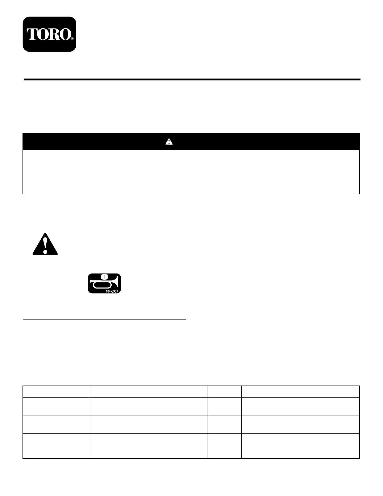
1.Behindthebattery-disconnectswitchontheright
sideofthemachine,remove1insulatorlug,nut,and
lockwasherfromthepositiveterminal(Figure1or
Figure2).
2.Usingthehardwareremoved,attach1ringterminal
ofthewiringharnesstothepositiveterminal(Figure
1orFigure2).
Removethekeyfromtheignitionswitch
beforeyoudoanymaintenance.
4.Disconnectthebattery.RefertoyourOperator’sManual.
5.Removetherightsidepanelandthenosepanel.Refer
toyourOperator’ sManual.
Figure1
RT600
1.Insulatorlug4.Ringterminal
2.Nut5.Positiveterminal
3.Lockwasher6.Battery-disconnectswitch
2
Page 3
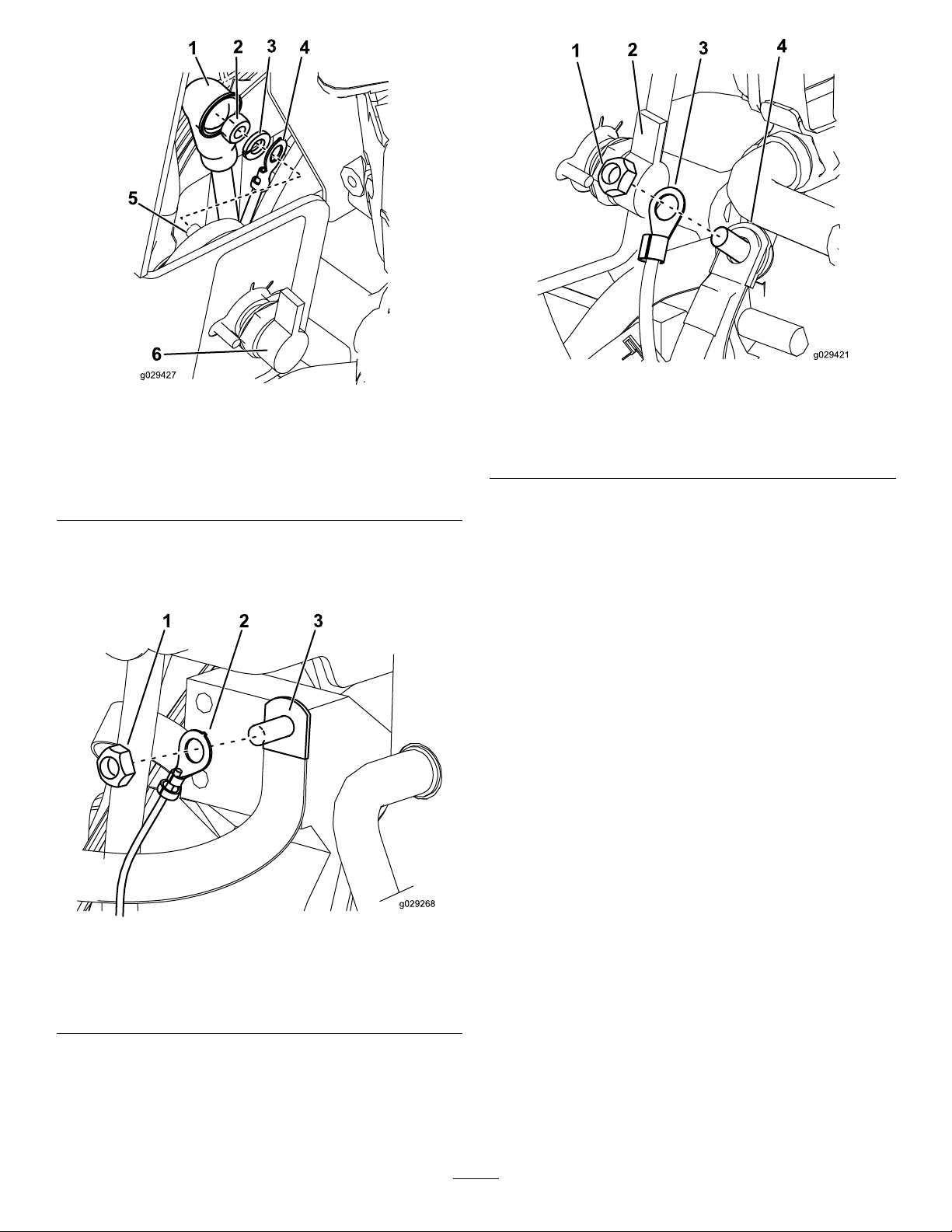
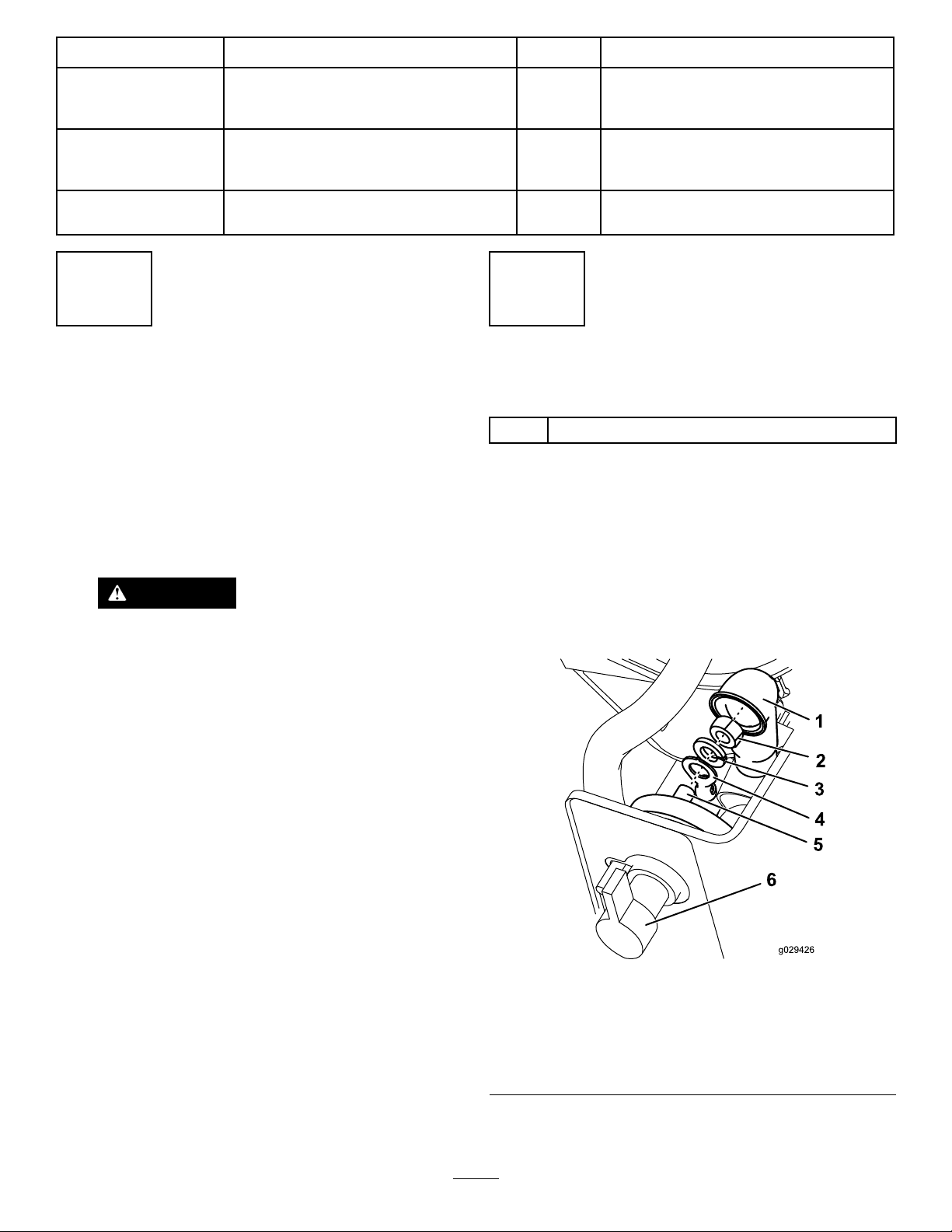
Figure2
RT1200
1.Insulatorlug4.Ringterminal
2.Nut5.Positiveterminal
3.Lockwasher6.Battery-disconnectswitch
3.Removethenutattachedtotheengineground.
4.Usingthenutyouremoved,attachtheotherring
terminaltotheengineground(Figure3orFigure4).
Figure4
RT1200
1.Nut3.Ringterminal
2.Battery-disconnectswitch4.Engineground
5.Routethewiringharnessbeneaththesideledgetoward
thenoseofthemachine.
Figure3
RT600
1.Nut3.Engineground
2.Ringterminal
3
Page 4

3
MountingtheHorn(RT600 UnitsOnly)
Partsneededforthisprocedure:
1Horn
1Mountingbracket
1Threadlocker
Procedure
1.Removethemountingstrapandnutfromthehorn.
Note:Discardthemountingstrap.
2.Applythethreadlockertothehornstud.
3.Installthehornontothemountingbracketandtorque
to7.73to12.8N-m(5.7to9.5ft-lb)(Figure5).
Note:Orientthehornopeningdownward.
Figure6
1.Mountingbracket3.Nut
2.Bolt
5.Connectthewireharnesstothehornposts(Figure7).
Figure5
1.Mountingbracket3.Nut
2.Horn
4.Removetheforwardboltfromtheexistingbracket,
anduseittoinstallthemountingbracket(Figure6).
Figure7
Mountingbracketnotshown
1.Hornpost
4
Page 5

4
MountingtheHorn(RT1200
UnitsOnly)
Partsneededforthisprocedure:
1Horn
1Mountingbracket
1Threadlocker
Procedure
1.Removethemountingstrapandnutfromthehorn.
Discardthemountingstrap.
2.Applythethreadlockertothehornstud.
3.Installthehornontothemountingbracketandtorque
to7.73to12.8N-m(5.7to9.5ft-lb)(Figure8).
Note:Orientthehornopeningdownward.
Figure8
Figure9
1.Bolt3.Existingbracket
2.Mountingbracket
5.Connectthewiringharnesstothehornposts(Figure
10).
1.Horn3.Nut
2.Mountingbracket
4.Removetheforwardboltfromtheexistingbracket,
anduseittoinstallthemountingbracket(Figure9).
Figure10
Mountingbracketnotshown
1.Hornpost
5
Page 6

5
InstallingtheHornSwitch
Partsneededforthisprocedure:
1Hornswitch
1Decal
6
Cableties
Procedure
1.Ontheleftsideofthesteeringcolumn,removethe
plugshowninFigure11.
Figure12
1.Bolt2.Kickpanel
Figure11
1.Plug
2.Removethekickpanelbeneaththedashboard(Figure
12).
3.Connectthewiringharnesstothehornswitch(Figure
13).
Figure13
1.Hornswitch2.Wireharness
4.Unscrewtherubberbuttonfromthehornswitch.
5.Routehornswitchandwiringharnessupthroughthe
dashboardtotheholeinthedashboardandscrewthe
buttonbackontotheswitch(Figure14).
6
Page 7

Figure14
6
TestingtheHornFunction
NoPartsRequired
Procedure
Conrmthatthehornsoundswhenyoupressthehorn
buttonandstopswhenyoureleaseit.
Note:Ifthehorndoesnotsound,ensurethatthewiring
harnessconnectorsaresecure.
1.Decal
2.0.25cm(0.10inch)
6.InstallthedecalinthelocationshowninFigure14.
7.Connectthebattery.RefertoyourOperator’ sManual.
8.Turnthemainpowerdisconnectswitchandthe
ignitionkeytotheOnposition.
9.Securethewiringharnesstothetractionunitwiththe
cableties.Ensurethewiringharnesswillnotinterfere
withanymovingpartsandwillnotcontactpartsofthe
machinethatwillgethot.
10.Installthekickpanel(Figure12).
11.Installtherightsideandnosepanels.Refertoyour
Operator’sManual.
3.1.37cm(0.54inch)
4.Rubberbutton
7
Page 8

 Loading...