

Page 1
FormNo.3389-747RevA
ProSneak365VibratoryPlow
ModelNo.25403—SerialNo.314000001andUp
ModelNo.25403A—SerialNo.314000001andUp
ModelNo.25403C—SerialNo.314000001andUp
Registeratwww.T oro.com.
OriginalInstructions(EN)
*3389-747*A
Page 2
WARNING
CALIFORNIA
Proposition65Warning
Thisproductcontainsachemicalorchemicals
knowntotheStateofCaliforniatocausecancer,
birthdefects,orreproductiveharm.
Dieselengineexhaustandsomeofits
constituentsareknowntotheStateof
Californiatocausecancer,birthdefects,
andotherreproductiveharm.
Important:Thisengineisnotequippedwithaspark
arrestermufer.ItisaviolationofCaliforniaPublic
ResourceCodeSection4442touseoroperatetheengine
onanyforest-covered,brush-covered,orgrass-covered
land.Otherstatesorfederalareasmayhavesimilarlaws.
Theenclosed
Engine Owner's Man ual
issuppliedfor
informationregardingtheUSEnvironmentalProtection
Agency(EPA)andtheCaliforniaEmissionControl
Regulationofemissionsystems,maintenance,and
warranty.Replacementsmaybeorderedthroughthe
enginemanufacturer.
Introduction
Readthisinformationcarefullytolearnhowtooperateand
maintainyourproductproperlyandtoavoidinjuryand
productdamage.Youareresponsibleforoperatingthe
productproperlyandsafely.
YoumaycontactTorodirectlyatwww .Toro.comforproduct
andaccessoryinformation,helpndingadealer,ortoregister
yourproduct.
Wheneveryouneedservice,genuineT oroparts,oradditional
information,contactanAuthorizedServiceDealerorToro
CustomerServiceandhavethemodelandserialnumbersof
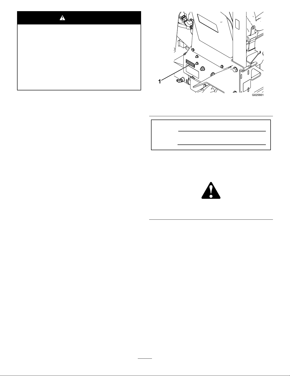
yourproductready.Figure1identiesthelocationofthe
modelandserialnumbersontheproduct.Writethenumbers
inthespaceprovided.
Figure1
1.Modelandserialnumberlocation
ModelNo.
SerialNo.
Thismanualidentiespotentialhazardsandhassafety
messagesidentiedbythesafetyalertsymbol(Figure2),
whichsignalsahazardthatmaycauseseriousinjuryordeath
ifyoudonotfollowtherecommendedprecautions.
Figure2
1.Safetyalertsymbol
Thismanualuses2wordstohighlightinformation.
Importantcallsattentiontospecialmechanicalinformation
andNoteemphasizesgeneralinformationworthyofspecial
attention.
©2014—TheToro®Company
8111LyndaleAvenueSouth
Bloomington,MN55420
Contactusatwww.Toro.com.
2
PrintedintheUSA
AllRightsReserved
Page 3

Contents
Safety
Safety...........................................................................3
SafeOperatingPractices...........................................3
SafetyandInstructionalDecals.................................6
ProductOverview.........................................................12
Controls...............................................................12
Specications........................................................14
Attachments/Accessories........................................14
Operation....................................................................15
AddingFuel...........................................................15
FillingtheFuelTank...............................................15
StartingandStoppingtheEngine..............................16
OperatingtheVibratoryPlow..................................16
RotatingtheWheels................................................18
CheckingtheInterlockSystem.................................18
TransportingtheMachine........................................19
Maintenance.................................................................20
RecommendedMaintenanceSchedule(s)......................20
PremaintenanceProcedures........................................21
OpeningtheHood.................................................21
Lubrication...............................................................21
GreasingtheMachine.............................................21
EngineMaintenance..................................................22
ServicingtheAirCleaner.........................................22
ServicingtheEngineOil..........................................23
ServicingtheDieselParticulateFilter(DPF)...............24
FuelSystemMaintenance...........................................25
CheckingtheFuelLinesandConnections..................25
DrainingtheFuelFilter/WaterSeparator...................25
ReplacingtheFuelFilterCanister..............................26
DrainingtheFuelTank...........................................26
ElectricalSystemMaintenance....................................26
ServicingtheBattery...............................................26
DriveSystemMaintenance.........................................27
ServicingtheTires..................................................27
ServicingtheTransmissionandAxles........................28
CoolingSystemMaintenance......................................29
ServicingtheCoolingSystem...................................29
BeltMaintenance......................................................30
CheckingtheAlternatorDriveBeltTension...............30
ReplacingtheDriveBelt..........................................30
ControlsSystemMaintenance.....................................31
CheckingtheParkingBrake.....................................31
AdjustingtheTractionDriveforNeutral....................31
CleaningtheDirectionalControlsLinkage
Assembly...........................................................32
HydraulicSystemMaintenance....................................32
ServicingtheHydraulicSystem.................................32
ROPSMaintenance....................................................36
CheckingandServicingtheROPS.............................36
Cleaning...................................................................37
RemovingDebrisfromtheMachine..........................37
CleaningtheChassis...............................................37
Storage........................................................................37
Troubleshooting...........................................................38
Improperuseormaintenancebytheoperatororowner
canresultininjury.Toreducethepotentialforinjury,
complywiththesesafetyinstructionsandalways
payattentiontothesafetyalertsymbol,which
means:
instruction.Failuretocomplywiththeinstructionmay
resultinpersonalinjuryordeath.
Caution
,
W ar ning
,or
Danger
—personalsafety
SafeOperatingPractices
Thisproductiscapableofamputatinghandsandfeet.Always
followallsafetyinstructionstoavoidseriousinjuryordeath.
WARNING
Engineexhaustcontainscarbonmonoxide,an
odorless,deadlypoisonthatcankillyou.
Donotruntheengineindoorsorinanenclosed
area.
Training
•ReadtheOperator'sManualandothertrainingmaterial.If
theoperator(s)ormechanic(s)cannotreadEnglish,itis
theowner'sresponsibilitytoexplainthismaterialtothem.
•Becomefamiliarwiththesafeoperationoftheequipment,
operatorcontrols,andsafetysigns.
•Alloperatorsandmechanicsshouldbetrained.The
ownerisresponsiblefortrainingtheusers.
•Neverletchildrenoruntrainedpeopleoperateorservice
theequipment.Localregulationsmayrestricttheageof
theoperator.
•Theowner/usercanpreventandisresponsiblefor
accidentsorinjuriesoccurringtopeople,ordamageto
property.
Preparation
•Evaluatetheterraintodeterminewhataccessoriesand
attachmentsareneededtoproperlyandsafelyperform
thejob.Onlyuseaccessoriesandattachmentsapproved
bythemanufacturer.
•Wearappropriateclothingincludinghardhat,safety
glasses,longpants,safetyshoes,reectorvests,
respirators,andhearingprotection.Longhair,loose
clothingorjewelrymaygettangledinmovingparts.
•Inspecttheareawheretheequipmentistobeusedand
removeallobjectssuchasrocks,toys,andwirewhichcan
bethrownbythemachine.
•Useextracarewhenhandlingfuels.Theyareammable
andvaporsareexplosive.
–Useonlyanapprovedcontainer
–Neverremovethefuelcaporaddfuelwiththeengine
running.Allowtheenginetocoolbeforerefueling.
Donotsmoke.
3
Page 4

–Neverrefuelordrainthemachineindoors.
–Knowthehandsignalsusedonyourjob.Followthe
instructionsoftheagmen,signals,etc.
•Checkthattheoperator'spresencecontrols,safety
switches,andshieldsareattachedandfunctioning
properly.Donotoperateunlesstheyarefunctioning
properly.
Operation
•Beforedigging,havetheareamarkedfor
undergroundutilities,anddonotdiginmarked
areas.
•Neverrunanengineinanenclosedarea.
•Beforestartingeachday,checkthemachineforoiloruid
leaks.Replacealldamaged,loose,wornormissingparts
andfollowthelubricationandmaintenanceprocedures
showninthismanual.
•Onlyoperateingoodlight,keepingawayfromholesand
hiddenhazards.
•Besurealldrivesareinneutralandparkingbrakeis
engagedbeforestartingtheengine.Onlystarttheengine
fromtheoperator'sposition.
•Slowdownanduseextracareonhillsides.Ground
conditionsmayadverselyaffectthestabilityofthe
machine.Usecautionwhenworkingonnewlydisturbed
earth.
•Allowadequatespacewhenturningthisunit.
•Slowdownandusecautionwhenmakingturnsandwhen
changingdirectionsonslopes.
•Neveroperatewithouttheguardssecurelyinplace.Be
sureallinterlocksareattached,adjustedproperly ,and
functioningproperty.
•Stoponlevelground,lowerimplements,disengagethe
auxiliaryhydraulics,engageparkingbrake,andshutoff
theenginebeforeleavingtheoperator'spositionforany
reason.
•Keephandsandfeetawayfrommovingattachments.
•Lookbehindanddownbeforebackinguptobesureof
aclearpath.
•Nevercarrypassengersandkeeppetsandbystanders
away.
•Slowdownandusecautionwhenmakingturnsand
crossingroadsandsidewalks.
•Donotoperatethemachineundertheinuenceof
alcoholordrugs.
•Usecarewhenloadingorunloadingthemachineintoa
trailerortruck.
•Usecarewhenapproachingblindcorners,shrubs,trees,
orotherobjectsthatmayobscurevision.
•Readallattachmentmanuals.
•Ensurethattheareaisclearofotherpeoplebefore
operatingthemachine.Stopthemachineifanyoneenters
thearea.
•Neverleavearunningmachineunattended.Alwaysstop
theengine,settheparkingbrake,andremovethekey
beforeleaving.
•Neverjerkthecontrols;useasteadymotion.
•Watchfortrafcwhenoperatingnearorcrossing
roadways.
•Donottouchpartswhichmaybehotfromoperation.
Allowthemtocoolbeforeattemptingtomaintain,adjust,
orservice.
•Checkforoverheadclearances(i.e.branches,doorways,
electricalwires)beforedrivingunderanyobjectsanddo
notcontactthem.
•Ensurethatyouoperatethemachineinareaswhere
therearenoobstaclesincloseproximitytotheoperator.
Failuretomaintainadequatedistancefromtrees,walls,
andotherbarriersmayresultininjuryasthemachine
backsupduringoperationiftheoperatorisnotattentive
tothesurroundings.Onlyoperatetheunitinareaswhere
thereissufcientclearancefortheoperatortosafely
maneuvertheproduct.
•Neverallowanyoneinthetrenchwhileoperatingthe
machine.
•Locatethepinchpointareasmarkedonthemachineand
attachmentsandkeephandsandfeetawayfromthese
areas.
•Beforeoperatingthemachinewithanattachment,ensure
thattheattachmentisproperlyinstalled.
•Lightningcancausesevereinjuryordeath.Iflightning
isseenorthunderisheardinthearea,donotoperate
themachine;seekshelter.
SlopeOperation
Slopesareamajorfactorrelatedtoloss-of-controland
tip-overaccidents,whichcanresultinsevereinjuryordeath.
Allslopesrequireextracaution.
•Avoidoperatingthismachineonslopes.
•Removeobstaclessuchasrocks,treelimbs,etc.fromthe
workarea.Watchforholes,ruts,orbumps,asuneven
terraincouldoverturnthemachine.Tallgrasscanhide
obstacles.
•UseonlyToro-approvedattachments.Attachmentscan
changethestabilityandtheoperatingcharacteristics
ofthemachine.Warrantymaybevoidedifusedwith
unapprovedattachments.
•Keepallmovementsonslopesslowandgradual.Donot
makesuddenchangesinspeedordirection.
•Avoidstartingorstoppingonaslope.Ifthemachine
losestraction,proceedgradually,straightdowntheslope.
•Avoidturningonslopes.Ifyoumustturn,turnslowly
andkeeptheheavyendofthemachineuphill.
•Donotoperateneardrop-offs,ditches,orembankments.
Themachinecouldsuddenlyturnoverifawheelgoes
overtheedgeofaclifforditch,orifanedgecavesin.
4
Page 5

•Donotoperateonwetgrass.Reducedtractioncould
causesliding.
connectingordisconnectingitfromthebattery.W ear
protectiveclothinganduseinsulatedtools.
•Donotparkthemachineonahillsideorslopewithout
loweringtheattachmenttotheground,settingtheparking
brake,andchockingthewheels.
•Onlyoperatethemachineonlevelgroundwhenthe
machineisinthenarrowwheelconguration.
RolloverProtectionStructure(ROPS)
System
•BeforeoperatingamachinewithaROPS(rollover
protectionstructure),ensurethattheseatbeltisingood
conditionandissecurelyattachedtothemachine.
•Alwayswearaseatbeltwhenoperatingamachinewith
aROPS.
•InspecttheROPSattheintervalrecommendedinthis
manualorwhentheROPShasbeeninanaccident.
•RepairadamagedROPSusingonlygenuineToro
replacementparts;donotrepairormodifytheROPS.
•Checkcarefullyforoverheadclearances(i.e.branches,
doorways,electricalwires)beforedrivingunderany
objectsanddonotcontactthem.
•DonotremovetheROPSexceptwhenservicingor
replacingit.
•Donotaddweighttothemachinethatexceedsthegross
weightdisplayedontheROPSlabel.
•Keepallpartsingoodworkingconditionandallhardware
tightened.Replaceallwornordamageddecals.
•Keepnutsandboltstight.Keepequipmentingood
condition.
•Nevertamperwithsafetydevices.
•Keepthemachinefreeofgrass,leaves,orotherdebris
build-up.Cleanupoilorfuelspillage.Allowthemachine
tocoolbeforestoring.
•Useextracarewhenhandlingfuels.Theyareammable
andvaporsareexplosive.
–Useonlyanapprovedcontainer.
–Neverremovethefuelcaporaddfuelwhenthe
engineisrunning.Allowtheenginetocoolbefore
refueling.Donotsmoke.
–Neverrefuelthemachineindoors.
–Neverstorethemachineorfuelcontainerinside
wherethereisanopename,suchasnearawater
heaterorfurnace.
–Neverllacontainerwhileitisinsideavehicle,trunk,
pick-upbed,oranysurfaceotherthantheground.
–Keepcontainernozzleincontactwiththetankduring
lling.
•Stopandinspecttheequipmentifyoustrikeanobject.
Makeanynecessaryrepairsbeforerestarting.
MaintenanceandStorage
•Disengagetheauxiliaryhydraulics,lowertheattachment,
settheparkingbrake,stoptheengine,andremovethe
key.Waitforallmovementtostopbeforeadjusting,
cleaning,orrepairing.
•Cleandebrisfromattachments,drives,mufers,and
enginetohelppreventres.Cleanupoilorfuelspillage.
•Lettheenginecoolbeforestoringanddonotstorenear
ame.
•Donotstorefuelnearamesordrainindoors.
•Parkthemachineonlevelground.Neverallowuntrained
personneltoservicethemachine.
•Usejackstandstosupportcomponentswhenrequired.
•Carefullyreleasepressurefromcomponentswithstored
energy.
•Disconnectthebatterybeforemakinganyrepairs.
Disconnectthenegativeterminalrstandthepositive
last.Reconnectpositiverstandnegativelast.
•Keephandsandfeetawayfrommovingparts.Ifpossible,
donotmakeadjustmentswiththeenginerunning.
•UseonlygenuineTororeplacementpartstoensurethat
originalstandardsaremaintained.
•Batteryacidispoisonousandcancauseburns.Avoid
contactwithskin,eyes,andclothing.Protectyourface,
eyes,andclothingwhenworkingwithabattery.
•Batterygasescanexplode.Keepcigarettes,sparksand
amesawayfromthebattery.
•Keepyourbodyandhandsawayfrompinholeleaks
ornozzlesthatejecthighpressurehydraulicuid.Use
cardboardorpapertondhydraulicleaks;neveruse
yourhands.Hydraulicuidescapingunderpressurecan
penetrateskinandcauseinjuryrequiringsurgerywithina
fewhoursbyaqualiedsurgeonorgangrenemayresult.
•Chargebatteriesinanopenwellventilatedarea,away
fromsparkandames.Unplugthechargerbefore
5
Page 6
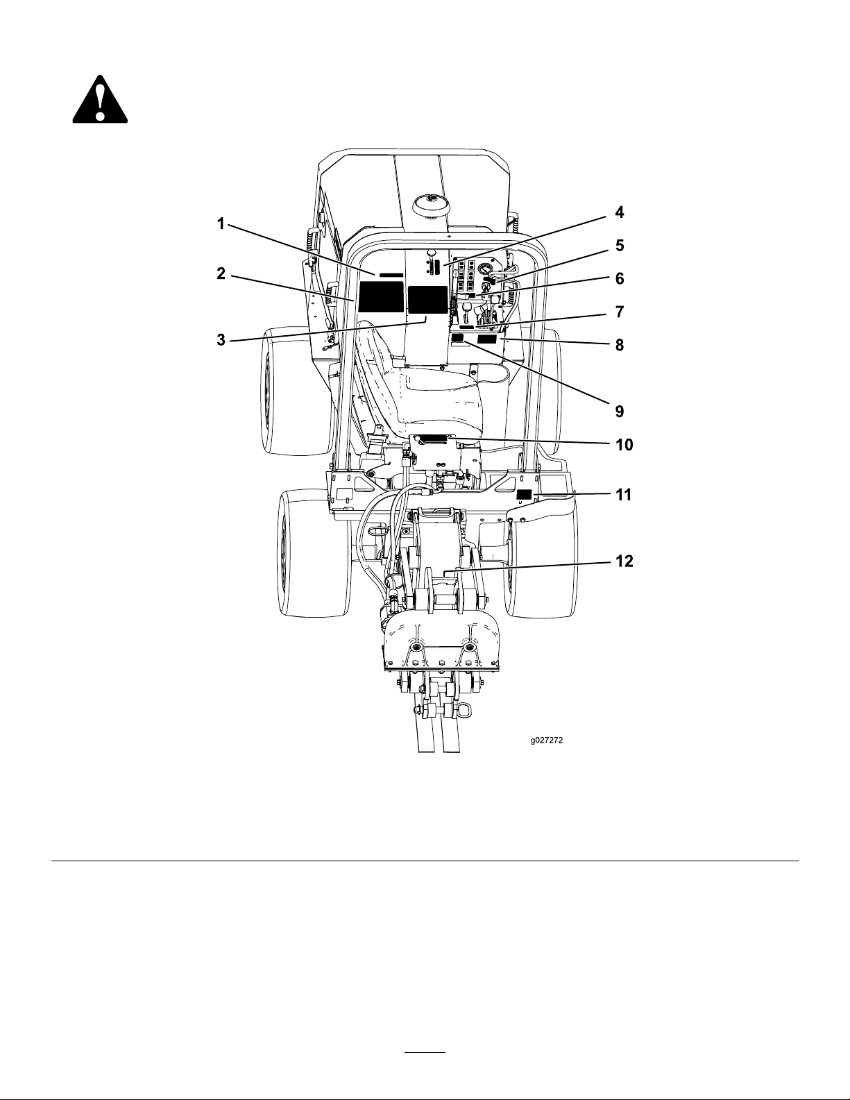
SafetyandInstructionalDecals
Safetydecalsandinstructionsareeasilyvisibletotheoperatorandarelocatednearanyareaofpotential
danger.Replaceanydecalthatisdamagedorlost.
Figure3
1.Decal117-27185.Decal130-73609.Decal125-6674
2.Decal130-43436.Decal130-434110.Decal127-1822
3.Decal127-18247.Decal130-736111.Decal125-4967
4.Decal130-43408.Decal125-668012.Decal125-6671
6
Page 7
g0272 73
1 2
10 11 1 2 13 1 4 2
3 4 5 6 7 8 9 1
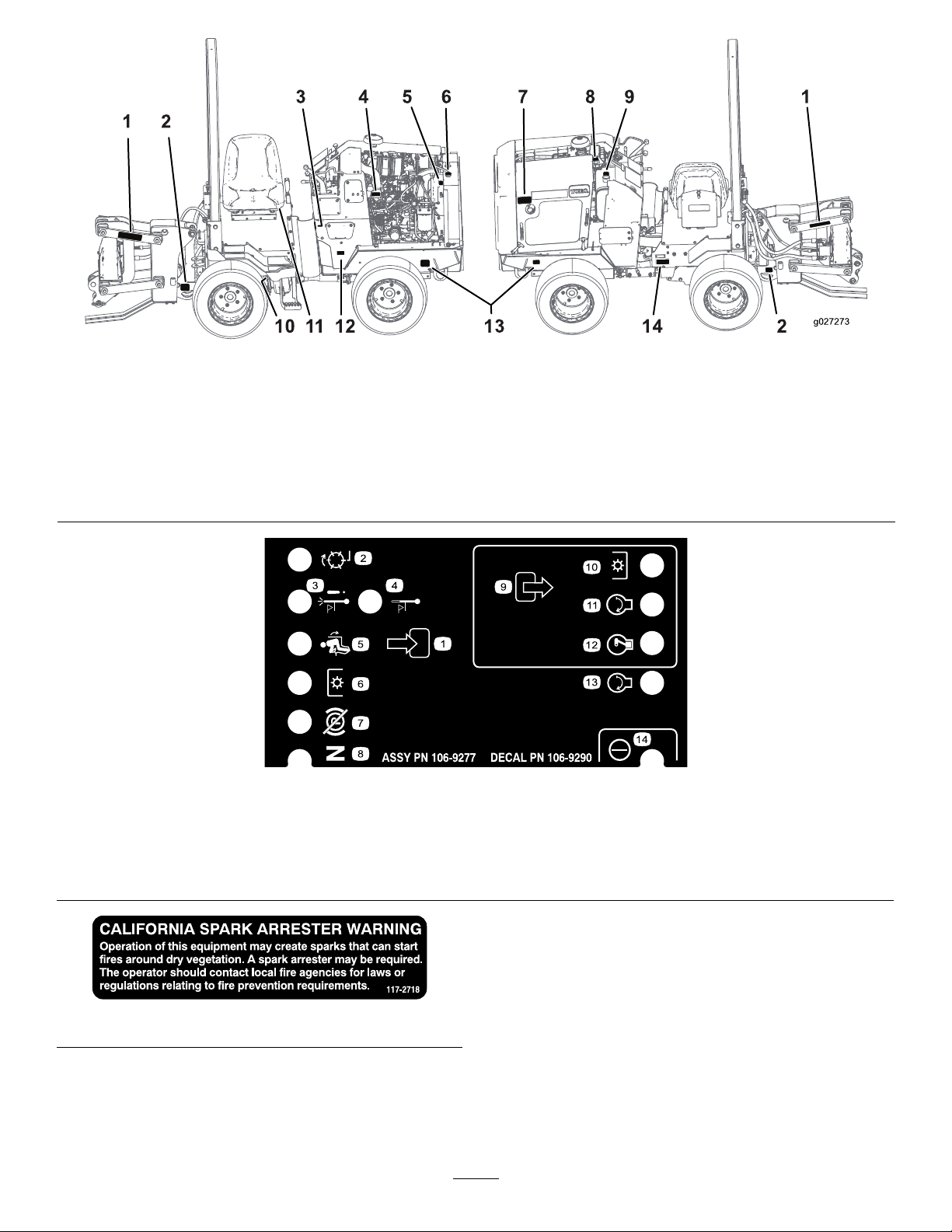
Figure4
1.Decal125-66846.Decal117-3276
2.Decal125-66947.Decal125-4963
3.Decal125-8491(behindtherubber
guard)
4.Decal125-66889.Decal125-848314.Decal125-6672
5.Decal120-0627(bothsidesof
machine)
8.Decal130-429113.Decal125-6694
10.Decal125-8487(behindthestep)
11.Decal125-6135(undertheseat)
12.Decal106-9290(insideofmachine)
106-9290
1.Inputs5.Inseat
2.Notactive
3.Hightemperatureshutdown
4.Hightemperaturewarning8.Neutral
6.PowerTake-off(PTO)10.PowerTakeOff(PTO)
7.ParkingbrakeOff11.Start
9.Outputs13.Start
12.EnergizetoRun(ETR)
14.Power
117-2718
7
Page 8
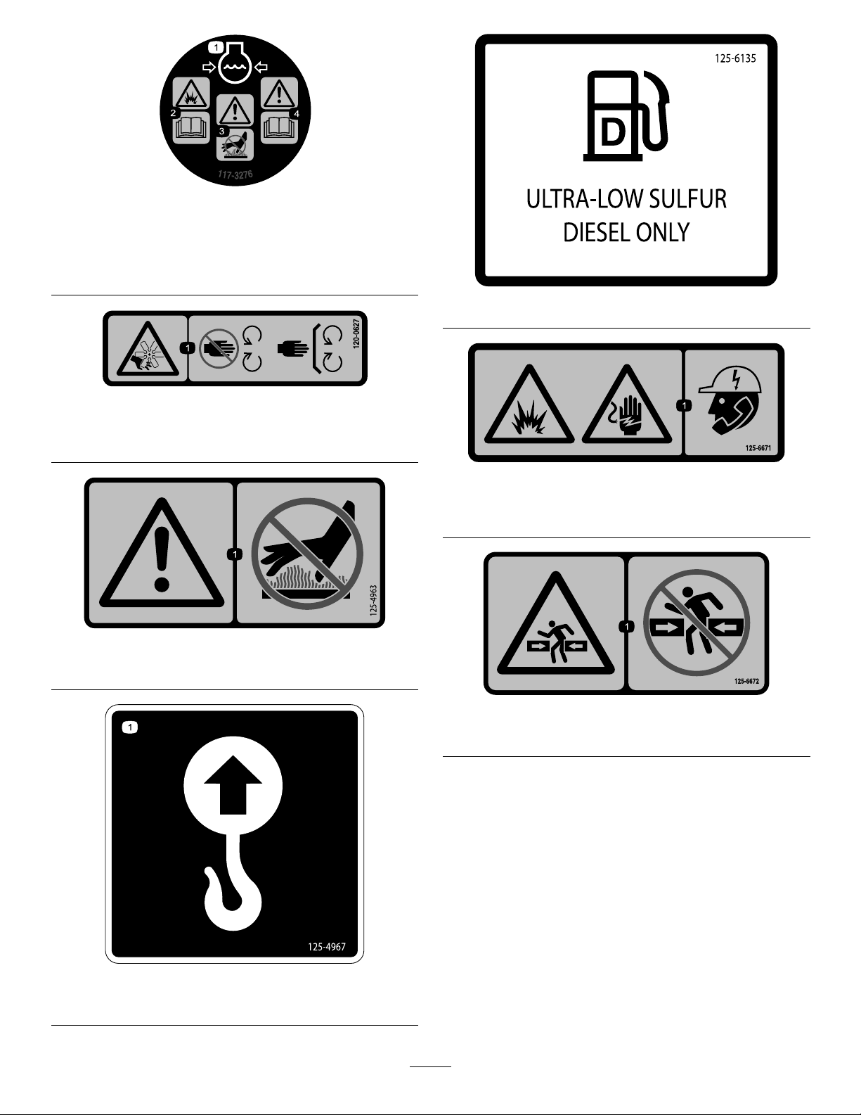
117-3276
1.Enginecoolantunder
pressure
2.Explosionhazard—read
theOperator'sManual.
3.Warning—donottouchthe
hotsurface.
4.Warning—readthe
Operator'sManual.
120-0627
1.Cutting/dismembermenthazard,fan—stayawayfrom
movingparts,keepallguardsandshieldsinplace.
125–6135
125-6671
1.Explosionhazard;electricshockhazard—calllocalutilities
beforedigging.
125–4963
1.Warning—keephandsawayfromhotsurfaces
125–4967
1.Liftpoint
125–6672
1.Crushinghazard—stayawayfromarticulatedjoints.
8
Page 9
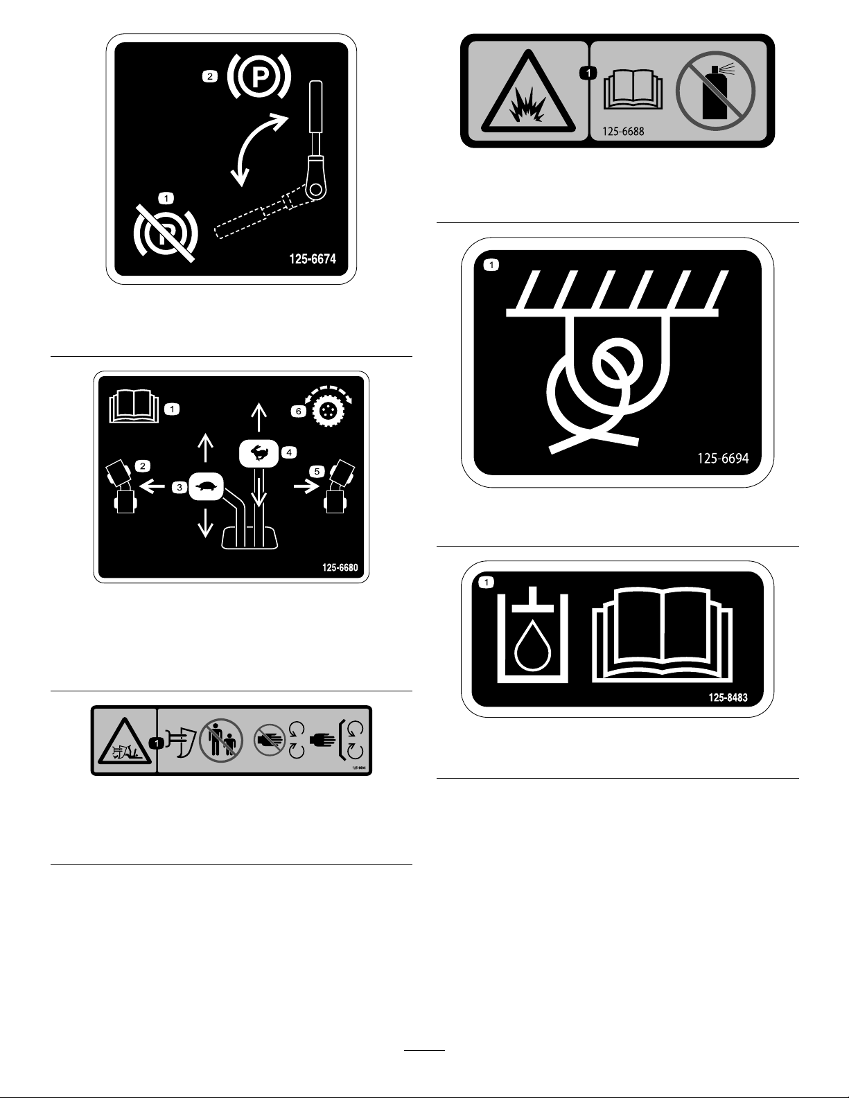
125–6688
1.Explosionhazard—ReadtheOperator’sManual;Donot
usestartinguid.
125–6674
1.Disengagetheparking
brake.
1.ReadtheOperator’s
Manual.
2.Turnleft
3.Slow
2.Engagetheparkingbrake.
125–6694
1.Tiedownlocation
125–6680
4.Fast
5.Turnright
6.Tractioncontrol
125–6684
1.Cutting/dismembermenthazard,plow—keepbystanders
awayfromtheplow;stayawayfrommovingparts;keepall
guardsandsafetiesinplace.
125–8483
1.Hydraulicuid;readtheOperator’sManual.
9
Page 10
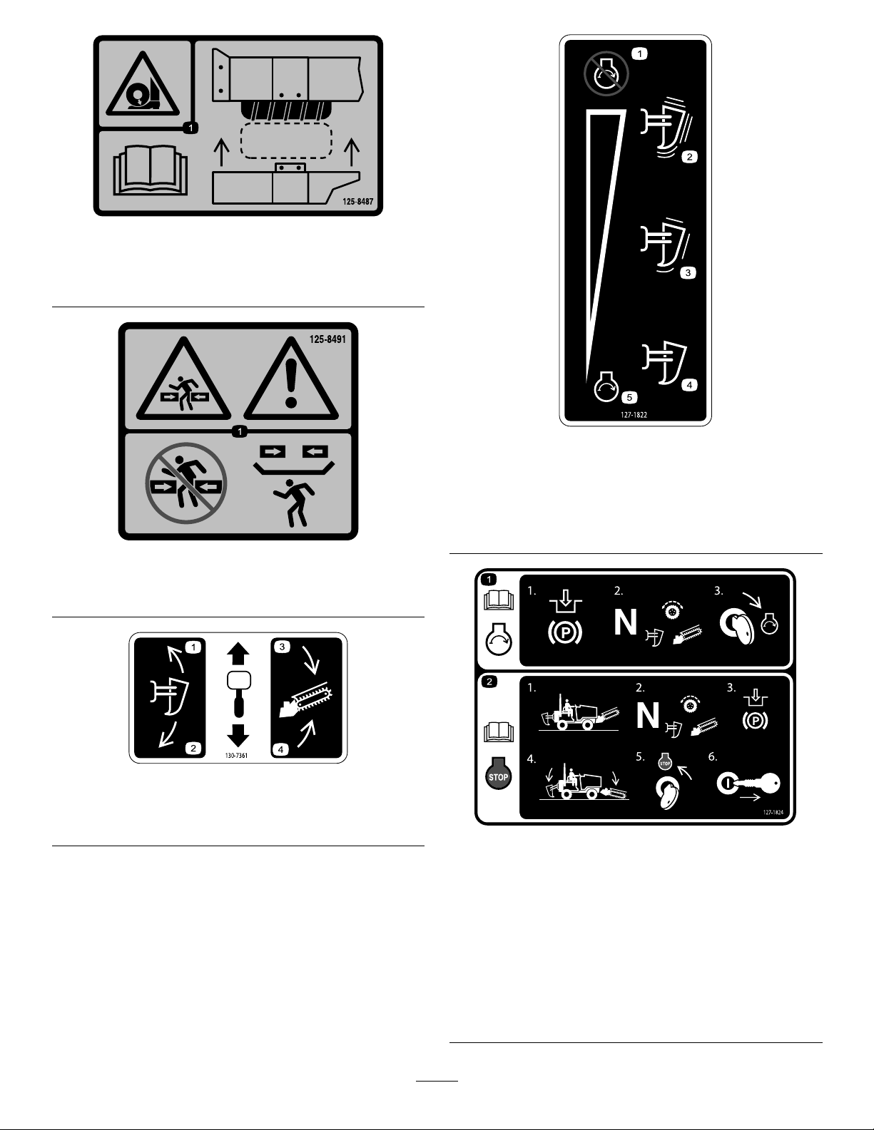
125–8487
1.Crushinghazard,tire—readtheOperator’sManual;the
extensionstepmustbeattachedwhenthetiresareinwide
ordoubledconguration.
127-1822
125–8491
1.Crushinghazard,warning—keepawayfromarticulated
joints;replacemissingsafetyshields.
130-7361
1.Raisetheplow3.Lowerthetrencher
2.Lowertheplower4.Raisethetrencher
1.Theenginecannotstart
withtheplowactive.
2.Highvibration5.Theenginecanstartwith
3.Lowvibration
4.Novibration
theplowinactive.
127-1824
1.Formoreinformationon
startingtheengine,read
theOperator'sManual—1)
Engagetheparkingbrake;
2)Settheplow,trencher,
anddrivetoneutral;3)
Turnthekeytotheengine
startposition.
2.Formoreinformationon
stoppingtheengine,read
theOperator'sManual—1)
Parkthemachineona
levelsurface;2)Setthe
plow,trencher,anddrive
toneutral;3)Engagethe
parkingbrake;4)Lower
allattachments;5)Turn
thekeytotheenginestop
position;6)Removethe
keyfromtheignition.
10
Page 11
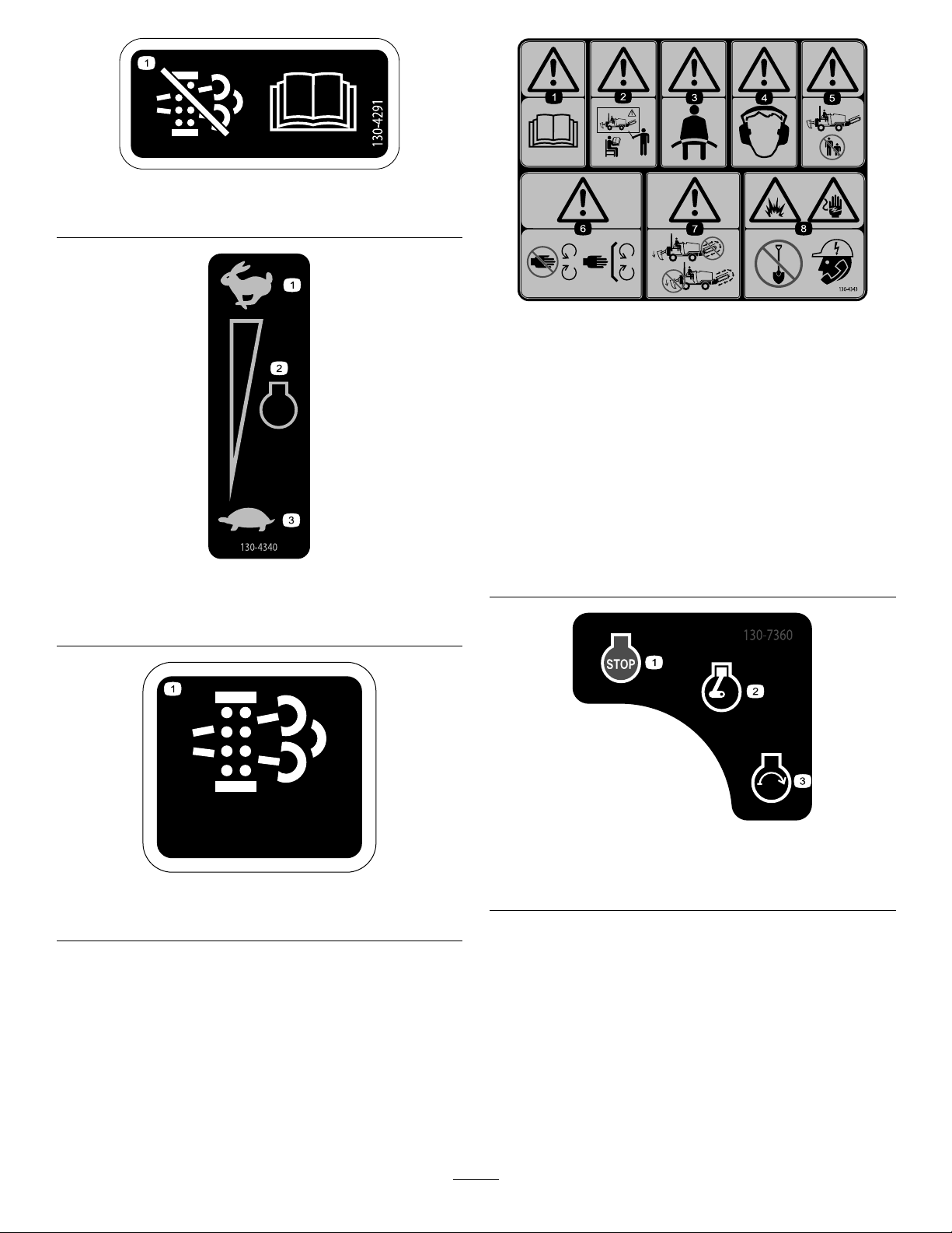
130-4291
130-4341
ACK
1.Regenerationinhibit—readtheOperator'sManual.
130-4343
1.Fast
2.Enginespeed
1.Warning—readthe
Operator'sManual.
2.Warning—donotoperate
themachineunlessyou
havereceivedinstruction.
3.Warning—wearaseatbelt.7.Warning—donotoperate
4.Warning—wearear
protection.
130-4340
3.Slow
5.Warning—keep
bystandersaway.
6.Warning—keepaway
frommovingparts;keep
allguardsandshieldsin
place.
thetrencherwhileusing
theplow;donotoperate
theplowwhileusingthe
trencher.
8.Explosionhazard;shock
hazard—beforedigging,
callthelocalutilities
service.
1.Regenerationacknowledge
130-7360
1.Engine—stop3.Engine—start
130-4341
2.Engine—run/warming
11
Page 12
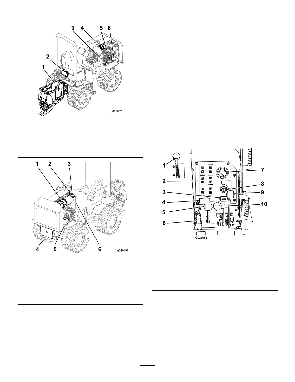
ProductOverview
1
2
3 4 5 6
g025662
1 2 3
4 5 6
1.Vibratoryplow
2.Vibratory-plow
control
Figure5
Right-sideview
3.Engine-oillter
4.Airlter6.Fuellter/water
5.Engine-oilcap
separator
Controls
Becomefamiliarwithallofthecontrolsbeforeyoustartthe
engineandoperatethemachine.
Throttle
Thethrottlecontrolstheenginespeed.Pushtheknobto
increasetheenginespeed.Pulltheknobtodecreasethe
enginespeed.
ParkingBrakeLever
Tosettheparkingbrake,pulltheleverupandpushitforward.
Toreleasetheparkingbrake,pulltheleverbackanddown.
AttachmentControlLever
Theattachmentcontrolleverhas2positions:raiseandlower.
Thecongurationofthemachinedetermineswhichdirect
raisesorlowerstheattachment;refertotheOperator’ sManual
foryourattachmenttocongureyourmachine.
1.Diesel-particulatelter
(DPF)
2.Regeneration-inhibit
switch
3.Fuses6.Hydraulictank
Figure6
Left-sideview
4.Battery
5.Coolant-expansiontank
Figure7
1.Throttle6.Parkingbrake
2.Indicatorlights7.Fuelgauge
3.Hourmeter8.Keyswitch
4.Regeneration-acknowledge
switch
5.Attachment-controllever
9.Traction-controllever
10.Creep-controllever
Traction-ControlLever
Thetractioncontrollevercontrolsthedirectionandspeedof
themachineduringtransport.Togoforward,pushthelever
forward.Toreverse,pulltheleverbackward.Thefurtheryou
pushorpullthelever,thefasterthemachinewilltravel.T o
turn,pushthelevertotheleftorright.
12
Page 13
Creep-ControlLever
Thecreepcontrollevercontrolsthedirectionandspeedof
themachinewhiletheattachmentsareinuse.Togoforward,
pushtheleverforward.Toreverse,pulltheleverbackward.
Thefurtheryoupushorpullthelever,thefasterthemachine
willtravel.Thecreep-controlleverwillnotreturntothe
Neutralpositiononitsown.
HourMeter
Thehourmeterdisplaysthenumberofhoursofoperation
thathavebeenloggedonthemachine.
KeySwitch
Thekeyswitch,usedtostartandstoptheengine,has3
positions:Off,On/Preheat,andStart.Tostarttheengine,
rotatethekeytotheOn/Preheatposition.Oncethe
glowplugindicatorlightisoff,rotatethekeytotheStart
position.Releasethekeywhenenginestartsanditwillmove
automaticallytotheOnposition.Tostoptheengine,rotate
thekeytotheOffposition.
FuelGauge
Thefuelgaugemeasurestheamountoffuelinthefueltank.
Vibratory-PlowControlLever
Thislevercontrolsthevibratoryplow.Toincreasethe
agitation,pushtheleverforward.Todecreasetheagitation,
pulltheleverback.Ifthevibratoryplowisinuse,usethe
creep-controllevertodrive.
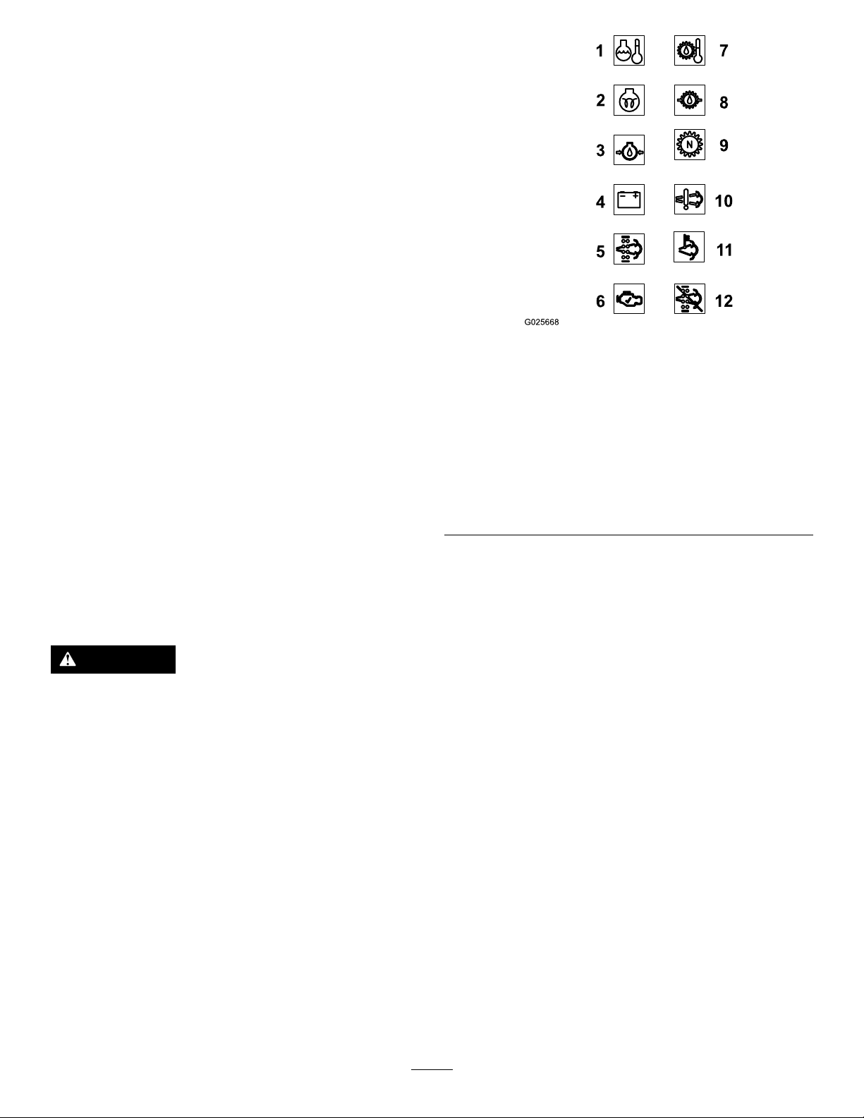
Diesel-ParticulateFilter(DPF)
Figure8
1.Engine-coolant-temperature
light
2.Glow-plugindicator
3.Engine-oil-pressurelight9.Neutralindicator
4.Chargeindicator10.Air-lterlight
5.Regeneration-requestlight11.High-temperature-exhaust
6.Check-enginelight
7.Hydraulic-oil-temperature
light
8.Hydraulic-oil-pressure
light
indicator
12.Regenerationinhibit
indicator
Engine-Coolant-TemperatureLight
Thislightwillilluminateiftheengineoverheats.Ifthelight
illuminateswhentheengineisrunning,stoptheengine,
removethekey,andcheckforapossiblecause.
CAUTION
Duringregeneration,thedieselparticulatelter
becomesextremelyhotandcancauseserious
burns.
Keepyourbodyandhandsawayfromtheengine
duringregeneration.
Thedieselparticulatelter(DPF)removesparticulatematter
fromtheexhaustandpreventsitfrombeingdischargedinto
theair.Astheparticulatescollectinthelter,theengine
performsaregenerationtopreventclogginganddecreased
engineperformance.Mostregenerationsareperformed
inthebackgroundandwillnotimpactoperation.These
backgroundregenerationshappenautomatically,unlessthe
regenerationinhibitswitchisactivated.
Overtime,ashaccumulatesintheDPFandabackground
regenerationisnotsufcienttounclogthelter.Whenthis
occurs,theregenerationrequestandcheckenginelights
illuminateonthecontrolpanel.Atthistime,thelterrequires
astationaryregenerationorneedstobeserviced;contactyour
AuthorizedServiceDealerformoreinformation.
Glow-PlugIndicator
Thislightwillilluminatewhiletheglowplugsareactive.
Whenthelightisoff,itissafetostartyourmachine.
Engine-Oil-PressureLight
Thislightilluminatesiftheengineoilpressuredropsbelowa
safelevelwhiletheengineisrunning.Ifthelightickersor
remainson,stopthevehicle,turnofftheengine,andcheck
theoillevel.Iftheoillevelwaslow ,butaddingoildoesnot
causethelighttogooutwhentheengineisrestarted,turnthe
engineoffimmediatelyandcontactyourAuthorizedService
Dealerforassistance.
ChargeIndicator
Thislightilluminateswhenthebatteryisbeingdischarged.If
thelightilluminatesduringoperation,stopthemachine,turn
offtheengine,andcheckforpossiblecauses.
13
Page 14

Regeneration-RequestLight
Regeneration-AcknowledgeSwitch
Thislightilluminatesalongwiththehigh-temperature-exhaust
indicatorwhenaregenerationisinprocess.Ifthislightis
illuminatedonitsown,astationaryregenerationispossible.
Whenaregenerationisrequestedbuttheregenerationinhibit
switchisactive,thislightwillblink.Ifthislightisilluminated
alongwiththecheckenginelight,yourDPFneedsservicing;
contactyourAuthorizedServiceDealerformoreinformation.
Check-EngineLight
Thislightilluminateswhenthereisanengineproblem.Ifthe
lightilluminateswhentheengineisrunning,stoptheengine,
removethekey ,andcheckforapossiblecause.Ifthislight
isilluminatedalongwiththeregenerationrequestlight,your
DPFneedsservicing;contactyourAuthorizedServiceDealer
formoreinformation.
Hydraulic-Oil-TemperatureLight
Thislightwillilluminateifthehydraulicsystemoverheats.
Ifthelightilluminateswhentheengineisrunning,stopthe
engine,removethekey ,andcheckforapossiblecause.
Hydraulic-Oil-FilterLight
Thislightilluminatesifthehydraulicoillterisinneedof
service.Ifthislightilluminateswhentheengineisrunning,
stoptheengine,removethekey,andservicethelter.
Thisswitchmanuallyactivatesastationaryregeneration.
Thislightontheswitchwillilluminatewhenastationary
regenerationisinprogress.Iftheregenerationrequestlight
andthelightontheswitcharebothblinking,theregeneration
inhibitswitchmustbeturnedoffforabackground
regenerationtooccur.Iftheregenerationrequestlightis
illuminatedandthelightontheswitchisblinking,contact
yourAuthorizedServiceDealerformoreinformation.
Regeneration-InhibitSwitch
Thisswitchwilldisabletheautomaticbackground
regeneration.
Specications
Note:Specicationsanddesignaresubjecttochange
withoutnotice.
Width
Width(narrowwheels)91cm(36inches)
Length(withvibratoryplow)291cm(114inches)
Height
Weight
Operatingcapacity251kg(553lb)
Tippingcapacity
Wheelbase
117cm(46inches)
216cm(85inches)
1,329kg(2,930lb)
717kg(1,580lb)
122cm(48inches)
NeutralIndicator
ThislightilluminateswhenallcontrolleversareintheNeutral
position.
Air-FilterLight
Thislightilluminatesiftheairlterisinneedofservice.If
thislightilluminateswhentheengineisrunning,stopthe
engine,removethekey ,andservicetheaircleaner.
High-Temperature-ExhaustIndicator
ThislightilluminateswhentheDPFisundergoing
regeneration.
Regeneration-InhibitIndicator
Thislightilluminateswhenautomaticbackground
regenerationhasbeenturnedoff.
Attachments/Accessories
AselectionofToroapprovedattachmentsandaccessoriesis
availableforusewiththemachinetoenhanceandexpand
itscapabilities.ContactyourAuthorizedServiceDealeror
Distributororgotowww .Toro.comforalistofallapproved
attachmentsandaccessories.
Important:UseonlyToroapprovedattachments.
Otherattachmentsmaycreateanunsafeoperating
environmentordamagethemachine.
14
Page 15

Operation
FillingtheFuelTank
Note:Determinetheleftandrightsidesofthemachine
fromthenormaloperatingposition.RefertoProduct
Overview(page12).
Important:Beforeoperating,checkthefuelandoil
level,andremovedebrisfromthemachine.Also,ensure
thattheareaisclearofpeopleanddebris.Y oushould
alsoknowandhavemarkedthelocationsofallutility
lines.
AddingFuel
Useultralowsulfurdieselfuel(ULSD)intheengineofthis
machine.Theuseofotherfuelscancausethelossofengine
powerandhighfuelconsumption.Thedieselfuelusedin
thismachinemustmeetthespecicationsofD975ofASTM
International.Seeyourdieselfueldistributor.TheD975
standarddenes2ULSDstandards,GradeNo.2-DS15
(regularULSD)andGradeNo.1-DS15(ahighervolatility
ULSDfuelwithalowergellingtemperaturethanregular
ULSD).
Fueltankcapacity:26.9L(7.1USgallons)
Usesummergradedieselfuel(No.2-D)attemperatures
above20°F(-7°C)andwintergrade(No.1-DorNo.
1-D/2-Dblend)belowthattemperature.Useofwintergrade
fuelatlowertemperaturesprovideslowerashpointand
coldowcharacteristicswhichwilleasestartingandreduce
fuellterplugging.
Useofsummergradefuelabove20°F(-7°C)willcontribute
towardlongerfuelpumplifeandincreasedpowercompared
towintergradefuel.
Important:Donotusekeroseneorgasolineinsteadof
dieselfuel.Failuretoobservethiscautionwilldamage
theengine.
WARNING
Fuelisharmfulorfatalifswallowed.Long-term
exposuretovaporscancauseseriousinjuryand
illness.
•Avoidprolongedbreathingofvapors.
•Keepfaceawayfromnozzleandfueltankor
conditioneropening.
•Keepfuelawayfromeyesandskin.
DANGER
Incertainconditions,fuelisextremelyammable
andhighlyexplosive.Areorexplosionfromfuel
canburnyouandothersandcandamageproperty.
•Fillthefueltankoutdoors,inanopenarea,when
theengineiscold.Wipeupanyfuelthatspills.
•Neverllthefueltankinsideanenclosedtrailer.
•Neversmokewhenhandlingfuel,andstayaway
fromanopenameorwherefuelfumesmaybe
ignitedbyaspark.
•Storefuelinanapprovedcontainerandkeepit
outofthereachofchildren.Neverbuymore
thana30-daysupplyoffuel.
•Donotoperatewithoutentireexhaustsystemin
placeandinproperworkingcondition.
DANGER
Incertainconditionsduringfueling,static
electricitycanbereleasedcausingasparkwhich
canignitethefuelvapors.Areorexplosionfrom
fuelcanburnyouandothersandcandamage
property.
•Alwaysplacefuelcontainersonthegroundaway
fromyourvehiclebeforelling.
•Donotllfuelcontainersinsideavehicleoron
atruckortrailerbedbecauseinteriorcarpets
orplastictruckbedlinersmayinsulatethe
containerandslowthelossofanystaticcharge.
•Whenpractical,removeequipmentfromthe
truckortrailerandrefueltheequipmentwithits
wheelsontheground.
•Ifthisisnotpossible,thenrefuelsuchequipment
onatruckortrailerfromaportablecontainer,
ratherthanfromafueldispensernozzle.
•Ifafueldispensernozzlemustbeused,keepthe
nozzleincontactwiththerimofthefueltank
orcontaineropeningatalltimesuntilfuelingis
complete.
15
Page 16

1.Parkthemachineonalevelsurface,lowerany
attachments,stoptheengine,andremovethekey.
2.Lifttheoperatorseattoaccessthefueltank.
Note:Iftheoutdoortemperatureisbelowfreezing,
storethemachineinagaragetokeepitwarmerand
aidinstarting.
3.Removethefueltankcap(Figure9).
Figure9
1.Fuel-tankcap
4.Fillthetanktoabout2.5cm(1inch)belowthetopof
thetank,notthellerneck,withdieselfuel.
5.Installthefuel-tankcap.
StoppingtheEngine
1.MovethethrottlelevertotheSlowposition.
2.Loweranyattachmentstotheground.
3.SetallcontrolstotheNeutralposition.
4.Settheparkingbrake.
5.TurntheignitionkeytotheOffposition.
Note:Iftheenginehasbeenworkinghardorishot,
letitidlefor5minutesbeforeturningtheignitionkey
off.Thishelpscooltheenginebeforeitisstopped.In
anemergency,youcanstoptheengineimmediately.
OperatingtheVibratoryPlow
Plowing
1.Removetherotationpin,placeitinthestorage
location,andstarttheengine(Figure10).
StartingandStoppingthe Engine
StartingtheEngine
1.Adjusttheseatandfastentheseatbelt.
2.EnsurethatallofthecontrolleversareintheNeutral
position.
3.MovethethrottlelevertotheSlowpositions.
4.RotatethekeytotheOn/Preheatposition.
5.Oncetheglowplugindicatorlightisoff,rotatethe
keytotheStartposition.Releasethekeywhenengine
startsanditwillmoveautomaticallytotheOnposition.
Important:Donotengagethestarterformore
than10secondsatatime.Iftheenginefailsto
start,allowa30secondcool-downperiodbetween
attempts.Failuretofollowtheseinstructionscan
burnoutthestartermotor.
6.Movethethrottlelevertodesiredsetting.
Important:Iftheengineisrunathighspeeds
whenthehydraulicsystemiscold(i.e.,whenthe
ambientairtemperatureisnearfreezingorlower),
hydraulicsystemdamagecouldoccur.When
startingtheengineincoldconditions,allowthe
enginetorunintheSlowpositionforatleast5
minutesbeforemovingthethrottletoFast(rabbit).
Figure10
1.Rotationpin
2.Whentheengineiswarm,pushthethrottleleverup
tofullthrottle.
3.Ifthemachineisequippedwithatrencher,movethe
attachmentselectorlevertothecableplowposition.
4.Usetheattachmentcontrollevertolowertheplowto
theground.
Note:Theenginewillturnoffin1secondifthe
operatorsseatisemptyandthedirectioncontrol,
trencher-digging-control,vibratory-plowlever,or
creep-controlleversaremovedfromtheNeutral
position.
5.Releasetheparkingbrake.
2.Storagelocation
16
Page 17

Note:Donotstarttheplowvibrationuntiltheblade
G025774
1
2
3
4
g021986
5
tiphasenteredtheground.
6.Movethevibratory-plowlevertostarttheplow
vibration.
7.Slowlylowertheplowbladeintothegroundasthe
machinemovesforward.
8.Usethecreepcontrollevertocontrolthedirectionand
speedofthemachineduringplowing.Themachinewill
moveinthesamedirectionthatyoumovethelever.
Note:ThemoreyoupushtheleverfromtheNeutral
position,thefasterthemachinewilltravel.Thelever
willstayinthispositionwhenyoureleasethelever.
MovethelevertotheNeutralpositiontostopthe
machinetravel.
9.Usethedirectionorcreepcontrolleverstosteerthe
machinetotheleftorright.
Important:Donotreversethemachinewiththe
plowbladeintheground.
Important:Slowlylifttheplowbladeoutofthe
groundasthemachinemovesforward.
Note:Decreasethemachinespeedifthetiresslip
orthebladeraisesoutofthegroundduringplow
operation.
10.Reducethespeedofthemachineandpullthe
vibratory-plowlevertostoptheplowvibrationbefore
raisingthebladeoutoftheground.
ChangingthePlowBlade
Figure11
1.Snap-ringpin
2.Pin
3.Pullthe2pinsoutoftheblade.
Note:Theplowbladesareheavy.Makesurethat1
personisholdingthebladewhiletheotherpersonis
removingthepins.
4.Placethenewbladeintotheplowbladeassemblyand
secureitwith2pinsand2snap-ringpins.
RemovingandInstallingtheSkidShoes
1.Raisetheplowabout91cm(36inches)offtheground.
2.Stoptheengineandremovethekey.
3.Removethe4bolts,4nuts,and8washersfromthe
skidshoes(Figure12).
Theplowbladesareheavy;use2peopletocompletethis
procedure.
1.Parkthemachineonalevelsurface,lowerany
attachments,andstoptheengine.
Note:Ensurethatthevibratoryplowisraisedhigh
enoughforthebladetobechanged.
2.Flipthe2circularsnapringsoverandremovethe
snap-ringpin(Figure11).
Figure12
1.Nut4.Washer
2.Washer5.Bolt
3.Skidshoes
4.Installthenewskidshoesandsecurethemwiththe
previouslyremovedhardware(Figure12).
17
Page 18

RotatingtheWheels
g022223
g023499
Thewheelscanbeinstalledtoprovideanarroworawide
overallwidthofmachine.Installthewheelswiththedeep
concavetowardthemachineforoperationintightareasor
theshallowconcavetowardthemachineforwiderstability.
Important:Onlyoperateonlevelgroundwiththe
narrowwheelconguration.
TireSize
23x10.5x12413820
26x12x12820730
PlyRating
Pressure
kPapsi
1.Parkthemachineonalevelsurface,lowerany
attachments,andstoptheengine.
2.Removetherearwheels.
3.Removethestepextensionfromthemachine(Figure
13).
Figure13
Figure14
CheckingtheInterlockSystem
Beforeusingthemachine,makethefollowinginterlock
systemchecks.Ifanyofthesechecksfails,contactyour
AuthorizedServiceDealerformoreinformation.
•Theengineshouldstartwiththetractioncontrolleverin
theNeutralpositionandtheparkingbrakeengaged.
•Theengineshouldstartwiththetractioncontrolleverin
theNeutralpositionandtheoperatorintheseat.
•Theengineshouldnotcrankwiththetractioncontrol
leveroutoftheNeutralpositionandtheoperatorinseat
and/ortheparkingbrakeengaged.
•Theengineshouldkillifthetractioncontrolleveris
movedoutoftheNeutralpositionwiththeengine
runningandtheparkingbrakeset.
4.Installthewheelsontheoppositesideofthemachine
fromwhicheachwasremoved.
5.Removethefrontwheelsandinstallthemonthe
oppositesideofthemachine.
Note:Besuretokeepthetreadgoinginthesame
direction(Figure14).
•Theenginemustkillifthetractioncontrolleverismoved
outoftheNeutralpositionwiththeenginerunningand
theoperatorisnotintheseat.
•Theenginemustkillifthevibratoryplowisengagedwith
theenginerunningandoperatornotintheseat.
•Theenginemuststopinapproximately1secondifthe
operatorleavestheseatedpositionwiththevibratory
plowengagedand/ordirectionalcontrolleveroutofthe
Neutralposition.
18
Page 19

TransportingtheMachine
1
g018921
1
g018922
LoadingtheMachine
Important:Ensurethatthetrailerandrampcan
supportbothyourweightplustheweightofthemachine
withanyattachments.
1.Starttheengine.
2.Movetheattachmentstotransportposition.
3.Securethetrailerhitchtoyourvehicleandputablock
atthefrontandrearofthetrailerwheels.
4.Movethemachineslowlyontothetrailer.
5.Lowertheattachmentsontothetrailerandsetthe
parkingbrake.
6.Stoptheengineandremovethekey.
7.Putblocksatthefrontandrearofeachtireofthe
machine.
8.Fastenthefronttie-downloopsofthemachinetothe
trailer(Figure15).
Figure15
1.Fronttie-downloop
9.Fastentherearofthemachinetothetrailerusing
chainsandabinder.
Figure16
1.Reartie-downloop
10.Measurethedistancefromthegroundtothehighest
pointofthemachinetodeterminetheclearanceheight.
11.Removetheblocksfromthefrontandrearofthe
trailerwheels.
Important:Aftertransportingthemachineafewmiles,
stopthetruck,ensurethatthetie-downsarestilltight
andthatthemachinehasnotmovedonthetrailer.
UnloadingtheMachine
1.Putablockatthefrontandrearofthemachineand
trailerwheels.
2.Removetheties,thenremovetheblocksfromthe
machine.
3.Starttheengineandreleasetheparkingbrake.Referto
StartingandStoppingtheEngine(page16).
4.Ensurethattheattachmentsareinthetransport
position.
5.Slowlymovethemachineoffofthetrailer.
Note:Usethereartie-downloop(Figure16)tosecure
themachine.
19
Page 20

Maintenance
Note:Determinetheleftandrightsidesofthemachinefromthenormaloperatingposition.RefertoProductOverview
(page12).
Important:Refertoyourengine
additionalmaintenanceprocedures.
Operator's Man ual
for
Note:DownloadafreecopyoftheElectricalSchematicor
HydraulicSchematicforyourmachinebyvisitingwww .Toro.com
andsearchingforyourmachinefromtheManualslinkon
thehomepage.
CAUTION
Ifyouleavethekeyintheignitionswitch,someonecouldaccidentlystarttheengineandseriouslyinjure
youorotherbystanders.
Removethekeyfromtheignitionbeforeyoudoanymaintenance.
RecommendedMaintenanceSchedule(s)
MaintenanceService
Interval
Aftertherst25hours
Aftertherst50hours
Aftertherst250hours
Beforeeachuseordaily
MaintenanceProcedure
•Replacethehydrauliclter.
•Changetheengineoilandlter.
•Changethehydraulicuid.
•Greasethemachine(Greaseimmediatelyaftereverywashing).
•Checktheairlterserviceindicatorlight(morefrequentlyifconditionsaredusty
orsandy).
•Checktheengineoil
•Checkthefuellter/waterseparator.
•Checkthetirepressure.
•Checkthelugnuts.
•Checkandrelltheenginecoolant.
•Checkthehydraulic-uidlevel.
•Removedebrisfromthemachineandscreens.
•Checkforloosefasteners.
Every50hours
Every100hours
Every250hours
Every400hours
Every500hours
•Drainwaterandothercontaminantsfromthefuellter/waterseparator.
•Checkthebatteryelectrolytelevel(replacementbatteryonly).
•Checktheaxleoillevels.
•Checkthecoolingsystemhoses.
•Checkthehydrauliclinesforleaks,loosettings,kinkedlines,loosemounting
supports,wear,weather,andchemicaldeterioration.
•Checkfordirtbuild-upinthechassis.
•Removetheaircleanercover,cleanoutanydebris,andchecktheairlterservice
indicatorlight(morefrequentlyifconditionsaredustyorsandy).
•Changetheengineoilandlter
•Drainandcleanthefueltank.
•Checkthebatterycableconnections.
•Checkthetransmissionoil.
•Cleantheradiator.
•Checkthefuellinesandconnectionsfordeterioration,damage,orlooseconnections.
•Replacetheairlter(morefrequentlyifconditionsaredustyorsandy).
•Replacethefuellter/waterseparator.
•CheckandmaintaintheROPS;checkitafteranaccident.
20
Page 21

MaintenanceService
g021987
Every1,000hours
Interval
MaintenanceProcedure
•Changethetransmissionoil.
•Changetheenginecoolant(SeeanAuthorizedServiceDealer).
•Checkthealternatordrivebelttension.
•Replacethehydrauliclter.
•Changethehydraulicuid.
Every1,500hours
Every2,000hours
Every3,000hours
Every4,000hours
Monthly
Yearlyorbeforestorage
•Replaceallmovinghydraulichoses.
•Replacethefuellinesandconnections.
•Cleanorreplacethedieselparticulatelter.
•Replacethealternatordrivebelt.
•Cleanthedirectionalcontrolslinkageassembly .
•Changetheengineoilandlter.
•Drainandcleanthefueltank.
•T ouchupchippedpaint.
Premaintenance
Procedures
Beforeopeninganyofthecovers,stoptheengineandremove
thekey.Allowtheenginetocoolbeforeopeninganycovers.
OpeningtheHood
Pulltherubberhoodlatch(oneachsideofthehood)from
thehoodbracket(Figure17)andopenthehood.
Lubrication
GreasingtheMachine
ServiceInterval:Beforeeachuseordaily(Grease
immediatelyaftereverywashing).
GreaseType:General-purposegrease.
1.Cleanthegreasettingswitharag.
2.Connectagreaseguntoeachtting(Figure18,Figure
19,andFigure20.
1.Hoodlatches
Figure17
Figure18
21
Page 22

g023247
EngineMaintenance
1 2 3 4 5 6 7
8
g026666
ServicingtheAirCleaner
ServiceInterval:Beforeeachuseordaily—Checkthe
airlterserviceindicatorlight(more
frequentlyifconditionsaredustyor
sandy).
Every250hours—Removetheaircleanercover,clean
outanydebris,andchecktheairlterserviceindicator
light(morefrequentlyifconditionsaredustyorsandy).
Every500hours—Replacetheairlter(more
frequentlyifconditionsaredustyorsandy).
Figure19
ServicingtheAir-cleanerCoverand
Body
Important:Servicetheaircleanerlteronlywhen
theserviceindicatorisilluminatedwhiletheengine
isrunning,after1000hoursofoperationoreachyear,
whicheveroccursrst.Changingtheairlterbeforeit
isnecessaryonlyincreasesthechanceofdirtentering
theenginewhenyouremovethelter.
1.Lowertheattachment,stoptheengine,andremove
thekey.
2.Checktheaircleanerbodyfordamagewhichcould
causeanairleak.Checkthewholeintakesystemfor
leaks,damage,orloosehoseclamps.Replaceorrepair
anydamagedcomponents.
3.Releasethelatchesontheaircleaner,andpullthe
air-cleanerhousingofftheaircleanerbody(Figure21).
Important:Donotremovetheairlters.
Figure20
Undersideview
1.Greasettings
3.Pumpgreaseintothettings(approximately3pumps).
4.Wipeupanyexcessgrease.
Figure21
1.Latch
2.Dustcap
3.Gasket
4.Bracket8.Dustvalve
5.Airlter
6.Safetylter
7.Air-cleanerhousing
4.Removethedustcapandcleantheinsidewith
compressedair.
5.Installthedustcapensuringthatthedustvalveonthe
bottomofthedustcapispointingdown.
6.Tightenthelatch.
22
Page 23

ReplacingtheFilters
g022272
-40 -30 -20 -10 0 10 20 30 40 50 C
-40 -22 -4 14 32 50 68 86 104 122 F
o
o
SAE 20W -50
SAE 15W -40
SAE 10W -30
SAE 5W -30
SAE 0W -30
Iftheairlterlightilluminates,performthefollowingsteps.
1.Gentlyslidetheprimarylteroutoftheaircleaner
body(Figure21).
Note:Avoidknockingthelterintothesideofthe
body.
2.Inspectthenewlter(s)fordamagebylookinginto
thelterwhileshiningabrightlightontheoutsideof
thelter.
Note:Holesinthelterwillappearasbrightspots.
Inspecttheelementfortears,anoilylm,ordamageto
therubberseal.Ifthelterisdamaged,donotuseit.
3.Cleantheairlterhousingwithamoistcloth.
4.Installthenewairlterelementensuringthatthe
elementisfullyseatedinsidetheairlterhousing.
5.Installthedustcapensuringthatthedustvalveonthe
bottomofthedustcapispointingdown.
6.Tightenthelatch.
ServicingtheSafetyFilter
Replacethesafetylter,nevercleanit.
Important:Neverattempttocleanthesafetylter.
Ifthesafetylterisdirty,thentheprimarylteris
damaged.Replacebothlters.
ServicingtheEngineOil
ServiceInterval:Aftertherst50hours—Changethe
engineoilandlter.
Beforeeachuseordaily—Checktheengineoil
Figure22
CheckingtheEngine-OilLevel
Theengineisshippedwithoilinthecrankcase;however,the
oillevelmustbecheckedbeforeandaftertheengineisrst
started.
Thebesttimetochecktheengineoiliswhentheengineis
coolbeforeithasbeenstartedfortheday.Ifithasalready
beenrun,allowtheoiltodrainbackdowntothesumpforat
least10minutesbeforechecking.Iftheoillevelisatorbelow
the‘add’markonthedipstick,addoiltobringtheoillevelto
theFullmark.Donotoverll.Iftheoillevelisbetweenthe
FullandAddmarks,nooiladditionisrequired.
1.Parkthemachineonalevelsurface,lowerany
attachments,stoptheengine,andremovethekey.
2.Unlocktheenginecoverlatchesandopentheengine
cover.
3.Removethedipstick,wipeitclean,installthedipstick
intothetube,andpullitoutagain.
Theoillevelshouldbeinthesaferange(Figure23).
Every250hours—Changetheengineoilandlter
Note:Changeoilandoilltermorefrequentlywhen
operatingconditionsareextremelydustyorsandy.
Theengineisshippedwithoilinthecrankcase;however,the
oillevelmustbecheckedbeforeandaftertheengineisrst
started.
Thecrankcasecapacityisapproximately5.2L(5.5quarts)
withthelter.
Usehigh-qualityengineoilthatmeetsthefollowing
specications:
OilType:Detergentdieselengineoil(APIserviceCJ-4or
higher)
Important:UsingnonCJ-4orhigheroilwillcauseDPF
plugginganddamagetheengine.
CrankcaseCapacity:w/lter,5.2L(5.5qt)
Viscosity:SeeFigure22.
Figure23
1.Dipstick
2.Oil-llcap
4.Iftheoilisbelowthesaferange,removethellcap
(Figure23)andaddoiluntilthelevelreachestheFull
mark.Donotoverll.
23
Page 24

Note:Whenusingdifferentoil,drainalloldoilfrom
thecrankcasebeforeaddingnewoil.
5.Installtheoilllcapanddipstick.
6.Closetheenginecoverandsecureitwiththelatches.
ChangingtheEngineOil
1.Starttheengineandletitrunfor5minutes.This
warmstheoilsoitdrainsbetter.
2.Parkthemachineonlevelground,lowerany
attachments,settheparkingbrake,stoptheengine,and
removethekey.
CAUTION
Componentswillbehotifthemachinehas
beenrunning.Ifyoutouchhotcomponents
youmaybeburned.
Allowthemachinetocoolbeforeperforming
maintenanceortouchingcomponentsunder
thehood.
3.Removethellercapandthedrainplug(Figure24).
Figure24
1.Oildrainplug
4.Whentheoilhasdrainedcompletely,installthedrain
plug.
Note:Disposeoftheusedoilatacertiedrecycling
center.
5.Slowlypourapproximately80%ofthespecied
amountofoilinthroughthevalvecover.
6.Checktheoillevel;refertoCheckingtheEngine-Oil
Level(page23).
7.Slowlyaddadditionaloiltobringtheleveltotheupper
holeonthedipstick.
8.Replacethellcap.
ChangingtheOilFilter
1.Draintheoilfromtheengine;refertoChangingthe
EngineOil(page24).
2.Placeashallowpanorragundertheltertocatchthe
oil.
3.Removetheoldlter(Figure25)andwipethesurface
ofthegasketsealonthelterhead.
Figure25
1.Oillter
4.Applyathinlayerofcleanoiltothegasketsealofthe
newoillter.
5.Applyathincoatofthecleanoilofthepropertype
throughthecenterholeofthelter.
6.Allow2minutesfortheoiltobeabsorbedbythelter
material,thenpouroffanyexcessoil.
7.Installthereplacementoilltertothelteradapterby
turningtheoillterclockwiseuntiltherubbergasket
contactsthelteradapter,thentightenthelteran
additional1/2turn.
8.Fillthecrankcasewiththepropertypeofnewoil;refer
toServicingtheEngineOil(page23).
9.Starttheengineandletitrunfor30seconds.Stopthe
engineandletthemachinecool.
10.Checktheengineoillevel;refertoCheckingthe
Engine-OilLevel(page23).
ServicingtheDiesel ParticulateFilter(DPF)
ServiceInterval:Every3,000hours
Overtime,ashaccumulatesintheDPFandabackground
regenerationisnotsufcienttounclogthelter.Whenthis
occurs,theregenerationrequestandcheckenginelights
illuminateonthecontrolpanel.Atthistime,thelterrequires
astationaryregenerationorneedstobereplaced;contact
yourAuthorizedServiceDealerformoreinformation.
Whentheashaccumulationreaches50g/L,theenginewill
de-rateitspowerto85%.Atthistime,theDPFneedstobe
24
Page 25

removedandreplacedwithacleanDPF .IftheDPFisnot
cleanedatthe50g/Llevel,theenginewillcontinuetorun
atthede-rated85%powerleveluntiltheashaccumulation
reaches60g/L.Whentheashlevelreaches60g/L,the
enginewillde-rateto50%power.Atthistime,theDPFis
fullypluggedandneedstoberemovedandreplacedwitha
cleanDPF;contactyourAuthorizedServiceDealerformore
information.
FuelSystem
Maintenance
DANGER
Undercertainconditions,dieselfuelandfuel
vaporsarehighlyammableandexplosive.Are
orexplosionfromfuelcanburnyouandothersand
cancausepropertydamage.
•Useafunnelandllthefueltankoutdoors,in
anopenarea,whentheengineisoffandiscold.
Wipeupanyfuelthatspills.
•Donotllthefueltankcompletelyfull.Addfuel
tothefueltankuntilthelevelis25mm(1inch)
belowthebottomofthellerneck.Thisempty
spaceinthetankallowsthefueltoexpand.
•Neversmokewhenhandlingfuel,andstayaway
fromanopenameorwherefuelfumesmaybe
ignitedbyaspark.
•Storefuelinaclean,safety-approvedcontainer
andkeepthecapinplace.
CheckingtheFuelLinesand Connections
ServiceInterval:Every400hours/Yearly(whichever
comesrst)—Checkthefuellinesand
connectionsfordeterioration,damage,
orlooseconnections.
Every2,000hours/Every2years(whichevercomes
rst)—Replacethefuellinesandconnections.
Inspectthefuellinesandconnectionsfordeterioration,
damage,orlooseconnections.Tightenanylooseconnections
andcontactyourAuthorizedServiceDealerforassistance
inxingdamagedfuellines.
DrainingtheFuelFilter/Water Separator
ServiceInterval:Beforeeachuseordaily—Checkthefuel
lter/waterseparator.
Every50hours—Drainwaterandothercontaminants
fromthefuellter/waterseparator.
1.Locatethefuellterontherightsideoftheengineand
placeacleancontainerunderit.
2.Loosenthedrainvalveonthebottomofthelter
canisterandallowthewatertodrain.
3.Whennished,tightenthedrainvalve.
25
Page 26

ReplacingtheFuelFilter Canister
ServiceInterval:Every500hours—Replacethefuel
lter/waterseparator.
1.Cleanthelterheadandtheoutsideofthefuellter.
2.Turntheltercounterclockwiseandremovethelter
fromthelterhead.
3.Lubricatethegasketonthenewltercanisterwith
cleanoil.
4.Installtheltercanisterbyhanduntilthegasket
contactsthelterhead,thenrotateitanadditional
1/2turn.
ElectricalSystem
Maintenance
ServicingtheBattery
ServiceInterval:Every100hours—Checkthebattery
electrolytelevel(replacementbattery
only).
Every250hours—Checkthebatterycable
connections.
WARNING
5.Starttheengineandcheckforleaks.
DrainingtheFuelTank
ServiceInterval:Every250hours
HaveanAuthorizedServiceDealerdrainandcleanthefuel
tank.
CALIFORNIA
Proposition65Warning
Batteryposts,terminals,andrelated
accessoriescontainleadandleadcompounds,
chemicalsknowntotheStateofCalifornia
tocausecancerandreproductiveharm.
Washhandsafterhandling.
Important:Thefollowingproceduresapplywhen
servicinga(dry)batterythathasreplacedtheoriginal
battery.Theoriginal(wet)batterydoesnotrequire
service.
Alwayskeepthebatterycleanandfullycharged.Useapaper
toweltocleanthebatterycase.Ifthebatteryterminalsare
corroded,cleanthemwithasolutionof4partswaterand
1partbakingsoda.Applyalightcoatingofgreasetothe
batteryterminalstoreducecorrosion.
Voltage:12V ,1000ColdCrankingAmps
ChargingtheBattery
WARNING
Chargingthebatteryproducesgassesthatcan
explode.
Neversmokenearthebatteryandkeepsparksand
amesawayfrombattery.
Important:Alwayskeepthebatteryfullycharged(1.265
specicgravity).Thisisespeciallyimportanttoprevent
batterydamagewhenthetemperatureisbelow0°C
(32°F).
1.Chargethebatteryfor10to15minutesat25to30
ampsor30minutesat4to6amps(Figure26).
Note:Donotoverchargethebattery.
26
Page 27

G025670
Figure26
g023497
1
4
3
5
2
1.Positivebatterypost
2.Negativebatterypost
3.Red(+)chargerlead
4.Black(-)chargerlead
2.Whenthebatteryisfullycharged,unplugthecharger
fromtheelectricaloutlet,thendisconnectthecharger
leadsfromthebatteryposts(Figure26).
3.Replacethebatterycover.
DriveSystem
Maintenance
ServicingtheTires
CheckingtheTiresandLugNuts
ServiceInterval:Beforeeachuseordaily—Checkthetire
pressure.
Beforeeachuseordaily—Checkthelugnuts.
•Donotexceedtheratedtirepressure.Toensurelongtire
lifeandsafehandling,checktirepressuredaily,referto
CheckingtheTirePressure(page27).
•Inspecttiresforcuts,slashes,orbulges.Tireswithdefects
needtobereplacedorrepairedforproperhandlingand
safety.
•Checkdailytoensurethatalllugnutsaretight.Torque
thelugnutsto81-95N-m(60-70ft-lb).
Figure27
CheckingtheTirePressure
Maintaintheairpressureinthetiresasspecied.Checkthe
tireswhentheyarecoldtogetthemostaccuratereading.
TireSize
23x10.5x12413820
26x12x12820730
PlyRating
Note:Usealowertirepressurewhenoperatinginsandysoil
conditionstoprovidebettertractionintheloosesoil.
Pressure
kPapsi
27
Page 28

ServicingtheTransmission
1
2
g022229
1
2
g022229
1
g026665
andAxles
Transmissionoilspecication:SAE80W140API
classicationlevelGL5
Transmissionoilcapacity:approximately0.47L(0.5qt)
Axleoilspecication:SAE80W140APIclassicationlevel
GL5
Frontaxleoilcapacity:approximately2.4L(2.5USqt)
Rearaxleoilcapacity:approximately2.4L(2.5USqt)
ToroPremiumGearOilisavailablefromanAuthorizedToro
ServiceDealer.Seethepartscatalogforpartnumbers.
CheckingtheTransmissionOil
ServiceInterval:Every250hours
1.Parkthemachineonalevelsurface,lowerany
attachments,andstoptheengine.
2.Cleantheareaaroundthellplugwithacleaning
solvent(Figure28).
ChangingtheTransmissionOil
ServiceInterval:Every1,000hours/Yearly(whichever
comesrst)
1.Parkthemachineonalevelsurface,lowerany
attachments,andstoptheengine.
2.Cleantheareaaroundthellplugwithacleaning
solvent(Figure29).
Figure29
1.Fillplug2.Drainplug
Figure28
1.Fillplug2.Drainplug
3.Removethellplug.
4.Checktheoillevel.
Note:Thelevelshouldbeevenwiththebottomof
thellplug
5.Iftheoillevelisbelowthebottomofthellplughole,
addoiltoraisetheleveluptothebottomofthell
plughole.
6.Installthellplug.
3.Removethellanddrainplug.
4.Drainthetransmissionoilintoacontainer.
5.Insertthedrainplug.
6.Fillthetransmissionuntiltheoillevelisevenwiththe
bottomofthellplughole.
CheckingtheAxleOilLevels
ServiceInterval:Every100hours
1.Parkthemachineonalevelsurface,lowerany
attachments,andstoptheengine.
2.Removethellplugfromoneoftheaxledifferentials
(Figure30).
Figure30
1.Fillplug
3.Checktheoillevel.
28
Page 29

Note:Theoillevelshouldbeevenwiththebottom
2
1
g026668
ofthellplughole.
CoolingSystem
4.Addoiltoraisetheoilleveluptothebottomofthe
llplughole.
5.Installthellplug.
6.Repeatfortheotherdifferential.
ChangingtheAxleOil
1.Placeadrainpanunderthepinionhousingoftheaxle.
2.Parkthemachineonalevelsurface,lowerany
attachments,andstoptheengine.
3.Removetheboltssecuringthecover,andremovethe
coverandgasket.
Figure31
1.Cover
4.Cleanthesurfacesandinstallanewgasket.
5.Installthecoveranddrainplug.
6.Removethellplug.
2.Drainpan
Maintenance
ServicingtheCoolingSystem
ServiceInterval:Beforeeachuseordaily—Checkandrell
theenginecoolant.
Every100hours—Checkthecoolingsystemhoses.
Every250hours—Cleantheradiator.
Every1,000hours/Y early(whichevercomes
rst)—Changetheenginecoolant(SeeanAuthorized
ServiceDealer).
Coolantspecication:amixtureof50%ethyleneglycol
and50%water
EngineandRadiatorcoolantcapacity:10.2L(10.8qt)
DANGER
Iftheenginehasbeenrunning,thepressurized,hot
coolantcanescapeandcausesevereburns.
•Donotremovetheradiatorcapwhentheengine
ishot.Alwaysallowtheenginetocoolatleast
15minutesoruntiltheradiatorcapiscool
enoughtotouchwithoutburningyourhand
beforeremovingtheradiatorcap.
•Donottouchradiatorandsurroundingparts
thatarehot.
•Usearagwhenopeningtheradiatorcap,and
openthecapslowlytoallowsteamtoescape.
7.Fillwithdifferentialoiluntiltheoilislevelwiththe
bottomofthellplughole.
8.Installthellplug.
9.Repeattheprocedurefortheotherdifferential.
DANGER
Rotatingshaftandfancancausepersonalinjury.
•Donotoperatethemachinewithoutthecovers
inplace.
•Keepngers,handsandclothingclearof
rotatingfananddriveshaft.
•Shutofftheengineandremovetheignitionkey
beforeperformingmaintenance.
CAUTION
Swallowingenginecoolantcancausepoisoning.
•Donotswallowenginecoolant.
•Keepoutofreachfromchildrenandpets.
29
Page 30

CheckingtheEngineCoolantLevel
1
G025771
1
2
3
4
g019025
Checklevelofcoolantatthebeginningofeachday.Capacity
ofthesystemis8.5L(9qt).
1.Carefullyremovetheradiatorcap.
BeltMaintenance
CheckingtheAlternatorDrive BeltTension
CAUTION
Iftheenginehasbeenrunning,the
pressurized,hotcoolantcanescapeandcause
burns.
•Donotopentheradiatorcapwhenthe
engineisrunning.
•Usearagwhenopeningtheradiatorcap,
andopenthecapslowlytoallowsteamto
escape.
ServiceInterval:Every1,000hours
1.Pushthedrivebeltwithyourthumbintheareashown
tocheckthetension(Figure33).
Note:Thedeectionshouldbebetween7to10mm
(1/4to3/8inch)underloadof98N-m(22ft-lb).If
thedeectionislessthan7mm(1/4inch)ormore
than10mm(3/8inch),adjustthetension.
Figure33
Figure32
1.Expansiontank
2.Checkthecoolantlevelintheradiator.
Note:Theradiatorshouldbelledtothetopofthe
llerneckandtheexpansiontanklledtotheFull
mark(Figure32).
3.Ifthecoolantislow ,adda50/50mixtureofwaterand
ethyleneglycolantifreeze.
Note:Donotusewateronlyoralcohol/methanol
basecoolants.
4.Installtheradiatorcapandexpansiontankcap.
ChangingtheEngineCoolant
HaveanAuthorizedServiceDealerchangetheenginecoolant
yearly.
Ifyouneedtoaddenginecoolant,refertoCheckingthe
EngineCoolantLevel(page30).
1.Checkthetensionofthe
belthere.
2.Pivotbolt4.Pivotbolt
2.Loosenthepivotandadjustingbolts.
3.Pullthealternatorawayfromtheenginetoincreasebelt
tensionortowardtheenginetodecreasebelttension,
thentightentheadjustingbolts.
4.Checkthebelttension.Ifthetensioniscorrect,tighten
thepivotbolts.
ReplacingtheDriveBelt
ServiceInterval:Every4,000hours—Replacethealternator
drivebelt.
1.Loosenthepivotbolts,theadjustingbolt,andmovethe
alternatortowardtheenginetoloosenthebelttension.
2.Removethedrivebeltandinstallthenewdrivebelt.
3.Adjustthebelttensiontobetween5to8mm(3/16to
5/16inch)underloadof98N-m(22ft-lb).
3.Adjustingbolt
30
Page 31

4.Runtheenginefor5minutesandcheckthetension;
thetensionshouldbebetween7to10mm(1/4to3/8
inch)underloadof98N-m(22ft-lb).
ControlsSystem
Maintenance
Thefactoryadjuststhecontrolsbeforeshippingthemachine
However,aftermanyhoursofuse,youmayneedtoadjust
thecontrols.
Important:Toadjustthecontrolsproperly,complete
eachprocedureintheorderlisted.
CheckingtheParkingBrake
MovetheparkingbrakelevertotheOnposition.Ifthereis
littleornoresistance,completethefollowingprocedure:
1.Parkthemachineonaatsurface,lowerany
attachments,stoptheengine,andremovethekey.
2.PuttheparkingbrakeintheOffposition.
3.Rotatethehandleoftheparkingbrakelever2or3
timesclockwise.
4.Applytheparkingbrake.
•Iftherewasresistance,theadjustmentiscorrect.
•Iftherewaslittleornoresistance,seean
AuthorizedServiceDealer.
AdjustingtheTractionDrive forNeutral
Whenpositionedonalevelsurface,themachinemustnot
creepwhenthetractionpedalisreleased.Ifitdoescreep,
adjustasfollows:
1.Parkthemachineonalevelsurface,stoptheengine,
andlowerthecuttingunittotheoor.
2.Blockthetires.
3.Loosenthejamnutsoneachendoftherod.
4.Adjustthemiddlenutdependingonwhichwaythe
machineiscreeping:
•Ifthemachineiscreepingforward,turnthemiddle
nutcounterclockwise.
•Ifthemachineiscreepingbackward,turnthe
middlenutclockwise.
31
Page 32

Figure34
g026710
1.Adjustmentnut
5.Tightenthejamnutsoneachendoftherod.
6.Testthemachinetoseeiffurtheradjustmentisneeded.
CleaningtheDirectional ControlsLinkageAssembly
ServiceInterval:Monthly
HydraulicSystem
Maintenance
ServicingtheHydraulic System
Hydraulicuidreservoircapacity:25.8L(6.8USgallons)
Useonlyoneofthefollowinguidsinthehydraulicsystem:
ToroPremiumAllSeasonHydraulicFluid(Availablein
5-gallonpailsor55-gallondrums.SeePartsCatalogoran
AuthorizedServiceDealerforpartnumbers.)
Alternateuids:IftheTorouidisnotavailable,otheruids
maybeusedprovidedtheymeetallthefollowingmaterial
propertiesandindustryspecications.W edonotrecommend
theuseofsyntheticuid.Consultwithyourlubricant
distributortoidentifyasatisfactoryproduct.
Note:Torowillnotassumeresponsibilityfordamage
causedbyimpropersubstitutions,souseonlyproducts
fromreputablemanufacturerswhowillstandbehindtheir
recommendation.
HighViscosityIndex/LowPourPoint
Anti-wearHydraulicFluid,ISOVG46
Spraythedirectioncontrolslinkageassemblywithcompressed
airasshowninFigure35.
Figure35
MaterialProperties:
St@40°C44to48 Viscosity,ASTMD445
St@100°C7.9to8.5
ViscosityIndexASTM
D2270
PourPoint,ASTMD97-34°Fto-49°F
FZG,Failstage
Watercontent(newuid)500ppm(maximum)
IndustrySpecications:VickersI-286-S(QualityLevel),
VickersM-2950-S(Quality
Level),DenisonHF-0
140to160
11orbetter
ReplacingtheHydraulicFilter
ServiceInterval:Aftertherst25hours
Every1,000hours
Important:Donotsubstituteanautomotiveoillteror
severehydraulicsystemdamagemayresult.
1.Positionthemachineonalevelsurface.
2.Loweranyattachments,stoptheengine,andremove
thekey.
3.Placeapanunderthehydraulicltertocatchtheuid.
4.Turnthehydraulic-oilltercounterclockwise,remove
anddiscardthelter(Figure36).
32
Page 33

1
g018923
Figure36
1.Hydraulic-oillter
5.Applyathincoathydraulicuidtotherubbergasket
onthereplacementlter.
6.Fillthehydrauliclterwithcleanhydraulicuid.
7.Installthereplacementhydrauliclterontothelter
head.Tightenitclockwiseuntiltheltercontactsthe
lterhead,thentightenthelteranadditional3/4turn.
CAUTION
Duringregeneration,thedieselparticulate
lterbecomesextremelyhotandcancause
seriousburns.
Keepyourbodyandhandsawayfromthe
engineduringregeneration.
5.Removethecapfromthellerneckandchecktheuid
levelonthedipstick(Figure37).
Theuidlevelshouldbebetweenthemarksonthe
dipstick.
8.Cleanupanyspilleduid.
9.Starttheengineandletitrunforabout2minutesto
purgeanyairfromthesystem.
10.Stoptheengineandcheckforleaks.
WARNING
Hydraulicuidescapingunderpressurecan
penetrateskinandcauseinjury.Fluidinjected
intotheskinmustbesurgicallyremoved
withinafewhoursbyadoctorfamiliarwith
thisformofinjuryorgangrenemayresult.
•Keepyourbodyandhandsawayfrom
pinholeleaksornozzlesthatejecthigh
pressurehydraulicuid.
•Usecardboardorpapertondhydraulic
leaks,neveruseyourhands.
CheckingtheHydraulic-FluidLevel
ServiceInterval:Beforeeachuseordaily
Important:Alwaysusethecorrecthydraulicuid.
Unspecieduidswilldamagethehydraulicsystem.
Figure37
1.Fillerneck2.Dipstick
6.Ifthelevelislow ,addenoughuidtoraiseittothe
properlevel.
7.Installthecaponthellerneck.
8.Closethehood.
ChangingtheHydraulicFluid
ServiceInterval:Aftertherst250hours
Every1,000hours/Yearly(whichevercomesrst)
1.Positionthemachineonalevelsurface.
2.Removetheupperleftpaneloftheconsole(Figure38).
1.Parkthemachineonalevelsurface,andlowerany
attachments.
2.Stoptheengine,removethekey,andallowtheengine
tocool.
3.Openthehood.
4.Cleantheareaaroundthellerneckofthehydraulic
tank.
33
Page 34

1.Hoseclamp
g026707
Figure40
Figure38
1.Upperleftpanel
2.Hydraulictank
3.Placealargedrainpan(capableofholding57liters(15
USgallons)onthegroundunderthehydraulictank.
4.Removethehydraulictankcapanduseapumpto
emptythehydraulictank.
5.Removethelowerrightsidecoverplateandloosenthe
hoseclampholdingthesuctionhosetothehydraulic
tank(Figure39).
7.Disconnecttheelectricalleadtotheoiltemperature
sendingunitatthebottomofthereservoir.
8.Loosenthehydraulictankstrapsandremovethe
hydraulictankfromthemachine(Figure41).
Figure41
9.Flushthereservoirwithcleaningsolvent.
Figure39
1.Hoseclamp
6.Removetheleftsidecoverplateandloosenthe3hose
clampsunderthehydraulictank(Figure40).
10.Removetheelbowadaptersandremoveandcleanthe
lterscreenswithcompressedair(Figure42).
34
Page 35

g026671
Figure42
11.Putthreadsealantonthethreadsofthesuctionscreen
andinstallthescreen,elbow,hose,andclamp.
12.Connecttheelectricalleadtotheoiltemperature
sendingunitatthebottomofthereservoir.
CheckingtheHydraulicLines
ServiceInterval:Every100hours—Checkthehydraulic
linesforleaks,loosettings,kinkedlines,
loosemountingsupports,wear,weather,
andchemicaldeterioration.(Make
necessaryrepairsbeforeoperating.)
Every1,500hours/Every2years(whichevercomes
rst)—Replaceallmovinghydraulichoses.
WARNING
Hydraulicuidescapingunderpressurecan
penetrateskinandcauseinjury.Fluidinjectedinto
theskinmustbesurgicallyremovedwithinafew
hoursbyadoctorfamiliarwiththisformofinjury
organgrenemayresult.
•Keepyourbodyandhandsawayfrompinhole
leaksornozzlesthatejecthighpressure
hydraulicuid.
•Usecardboardorpapertondhydraulicleaks;
neveruseyourhands.
13.Installthehosetothetankandsecuretheclamps.
14.Installthehydraulictankassembly.
15.Fillthehydraulictankwithapproximately25.8L(6.8
USgallons)ofToropremiumallseasonhydraulicuid
ISOVG46.
Disposeoftheusedoilatacertiedrecyclingcenter.
16.Installthedipstickcap.
17.Starttheengineandletitrunforafewminutes.
18.Stoptheengine.
19.Checkthehydraulicuidlevelandtopitoffif
necessary;refertoCheckingtheHydraulic-FluidLevel
(page33).
35
Page 36

ROPSMaintenance
CheckingandServicingthe ROPS
CheckingandCaringfortheSeatBelt
Beforeyouoperatethemachine,alwaysensurethattheROPS
andtheseatbeltareproperlyinstalledandingoodworking
order.
1.Checktheseatbeltfordamage,andreplaceallparts
thataredamaged.
2.Ensurethatthemountingboltsfortheseatbeltsare
tight.
3.Keeptheseatbeltscleanusingonlysoapandwater.
Note:Donotimmersetheseatbeltsinbleachordye,
becausethisweakensthebeltmaterial.
2.Checkthattheboltsandnutsthatattachtheseat-belt
retractorandbuckletotheseataretorquedto104to
115N-m(77to85ft-lb);refertoFigure43.
Note:Replaceanypartsthatarewornordamaged.
3.InspecttheROPSforcracks,rust,orholesinthe
ROPSandcomponentparts.
Note:Age,weather,andaccidentscausedamageto
theROPSandROPSparts.Ifyouhaveanydoubts
abouttheROPSsystem,contactanAuthorizedToro
ServiceDealer.
ReplacingaDamagedROPSSystem
IftheROPSsystemhasbeendamagedinanaccident,such
asarolloverorhittinganoverheadobjectduringtransport,
replaceanydamagedROPScomponentstorestoretheROPS
systemtoitsoriginallevelofprotection.
Afteranaccident,checkthefollowingitemsfordamage:
CheckingandMaintainingtheROPS
ServiceInterval:Every500hours
Important:IfanypartoftheROPSsystemisdamaged,
replaceitbeforeyouoperatethemachine.
1.Checkthatthe4boltsthatsecuretheROPSbartothe
chassisofthemachinearetorquedto203to223N-m
(150to165ft-lb);refertoFigure43.
•TheROPSbar
•Operatorseat
•Seatbeltmounting
•Seatbelt
Beforeyouoperatethemachine,replacealldamagedROPS
components;contactanAuthorizedToroServiceDealer.
Important:Donottrytoweldorstraightenadamaged
ROPSbar.
Figure43
1.Seatbeltbolt3.ROPSbolts
2.Seatbeltretractorendbolt
36
Page 37

Cleaning
RemovingDebrisfromthe
Storage
1.Loweranyattachments,stoptheengine,andremove
thekey.
Machine
ServiceInterval:Beforeeachuseordaily
Important:Operatingtheenginewithblockedscreens
and/orcoolingshroudsremoved,willresultinengine
damagefromoverheating.
1.Parkthemachineonalevelsurface,lowerany
attachments,andstoptheengine.
2.Removethekeyandallowtheenginetocool.
3.Openthehood.
4.Cleananydebrisfromthefrontandsidescreens.
5.Wipeawayanydebrisfromtheaircleaner.
6.Cleananydebrisbuild-upontheengineandintheoil
coolernswithcompressedair.
Important:Itispreferabletoblowdirtout,rather
thanwashingitout.Ifwaterisused,keepitaway
fromelectricalitemsandhydraulicvalves.Do
notuseahigh-pressurewasher.High-pressure
washingcandamagetheelectricalsystemand
hydraulicvalvesordepletegrease.
7.Cleandebrisfromthehoodopening,mufer,andheat
shields.
8.Closethehood.
2.Removedirtandgrimefromtheentiremachine.
Important:Youcanwashthemachinewithmild
detergentandwater.Donotpressurewashthe
machine.Avoidexcessiveuseofwater,especially
nearthecontrolpanel,engine,hydraulicpumps,
andmotors.
3.Servicetheaircleaner;refertoServicingtheAir
Cleaner(page22).
4.Greasethemachine;refertoGreasingtheMachine
(page21).
5.Changethecrankcaseoil;refertoChangingtheEngine
Oil(page24).
6.Chargethebattery;refertoChargingtheBattery(page
26).
7.Checkandtightenallbolts,nuts,andscrews.Repairor
replaceanypartthatisdamaged.
8.Paintallscratchedorbaremetalsurfacesandreplace
anymissingordamageddecals.Paintanddecalsare
availablefromyourAuthorizedServiceDealer.
9.Drainthefuelfromthefueltank;refertoFuelSystem
Maintenance(page25).
10.Storethemachineinaclean,drygarageorstoragearea.
Removethekeyfromtheignitionswitchandkeepitin
amemorableplace.
CleaningtheChassis
ServiceInterval:Every100hours—Checkfordirtbuild-up
inthechassis.
Overtime,thechassisundertheenginecollectsdirtand
debristhatmustberemoved.Usingaashlight,openthe
hoodandinspecttheareaundertheengineonaregularbasis.
Whenthedebrisis2to5cm(1to2inches)deep,havean
AuthorizedServiceDealerremovetherearofthemachine,
fueltank,andbatteryandushthechassisclean.
11.Coverthemachinetoprotectitandkeepitclean.
37
Page 38

Troubleshooting
Problem
Thestarterdoesnotcrank.
Theenginecranks,butwillnotstart.
PossibleCauseCorrectiveAction
1.Thecontrolsarenotintheneutral
position.
2.Theelectricalconnectionsare
corrodedorloose.
3.Afuseisblownorloose.3.Correctorreplacethefuse.
4.Thebatteryisdischarged.
5.Therelayorswitchisdamaged.
6.Adamagedstarterorstartersolenoid.
7.Seizedinternalenginecomponents.7.ContactyourAuthorizedService
1.Thestartingprocedurewasperformed
incorrectly.
2.Thefueltankisempty.2.Fillthefueltankwithfreshfuel.
3.Thefuelshut-offvalveisclosed.3.Openthefuelshutoffvalve.
4.Dirt,water,stalefuel,orincorrectfuel
isinthefuelsystem.
5.Thefuellineisclogged.5.Cleanorreplacethefuelline.
6.Thereisairinthefuel.6.Bleedthenozzlesandcheckforair
7.Theglowplusareinoperative.
8.Thecrankingspeedistooslow.
9.Theaircleanerltersaredirty.9.Servicetheairlters.
10.Thefuellterisclogged.10.Replacethefuellter.
11.Thedieselparticularlterisclogged.11.ContactyourAuthorizedService
12.Improperfuelgradeisbeingusedfor
coldweatheruse.
13.Thecompressionislow.
14.Theinjectionnozzlesorpumpsare
malfunctioning.
15.TheETRsolenoidisbroken.
1.MoveallofthecontrolstotheNeutral
position.
2.Checktheelectricalconnectionsfor
goodcontact.
4.Chargethebatteryorreplaceit.
5.ContactyourAuthorizedService
Dealer.
6.ContactyourAuthorizedService
Dealer.
Dealer.
1.RefertoStartingandStoppingthe
Engine.
4.Drainandushthefuelsystem;add
freshfuel.
leaksatthefuelhoseconnections
andttingsbetweenthefueltankand
engine.
7.Checkthefuse,glowplugs,andwiring.
8.Checkthebattery,oilviscosity ,and
startingmotor(contactyourAuthorized
ServiceDealer).
Dealer.
12.Drainthefuelsystemandreplace
thefuellter.Addfreshfuelof
propergradeforambienttemperature
conditions.Youmayneedtowarmthe
entiremachine.
13.ContactyourAuthorizedService
Dealer.
14.ContactyourAuthorizedService
Dealer.
15.ContactyourAuthorizedService
Dealer.
38
Page 39

Problem
PossibleCauseCorrectiveAction
Theenginestarts,butdoesnotkeep
running.
Theengineruns,butknocksormisses.
1.Thefueltankventisrestricted.1.Loosenthecap.Iftheenginerunswith
2.Thereisdirtorwaterisinthefuel
system.
3.Thefuellterisclogged.3.Replacethefuellter.
4.Thereisairinthefuelsystem.4.Bleedthenozzlesandcheckforair
5.Improperfuelgradeisbeingusedfor
coldweatheruse.
6.Thesparkarrestorscreenisclogged.
7.Thefuelpumpisdamaged.7.ContactyourAuthorizedService
1.Thereisdirt,water,stalefuel,or
incorrectfuelisinthefuelsystem.
2.Theengineisoverheating.
3.Thereisairinthefuelsystem.3.Bleednozzlesandcheckforairleaksat
4.Theinjectionnozzlesaredamaged.
5.Thecompressionislow.
6.Theinjectionpumptimingisincorrect.
7.Thereisexcessivecarbonbuild-up.
8.Thereisinternalwearordamage.
thecaploosened,replacethecap.
2.Drainandushthefuelsystem;add
freshfuel.
leaksatfuelhoseconnectionsand
ttingsbetweenthefueltankand
engine.
5.Drainthefuelsystemandreplace
thefuellter.Addfreshfuelof
propergradeforambienttemperature
conditions.
6.Cleanorreplacethesparkarrestor
screen.
Dealer.
1.Drainandushthefuelsystem;add
freshfuel.
2.RefertotroubleshootingitemThe
engineoverheats.
thefuelhoseconnectionsandttings
betweenthefueltankandengine.
4.ContactyourAuthorizedService
Dealer.
5.ContactyourAuthorizedService
Dealer.
6.ContactyourAuthorizedService
Dealer.
7.ContactyourAuthorizedService
Dealer.
8.ContactyourAuthorizedService
Dealer.
Theenginewillnotidle.
1.Thefueltankventisrestricted.1.Loosenthecap.Iftheenginerunswith
2.Thereisdirt,water,stalefuel,or
incorrectfuelisinthefuelsystem.
3.Theaircleanerltersaredirty.3.Servicetheairlters.
4.Thefuellterisclogged.4.Replacethefuellter.
5.Thereisairinthefuel.5.Bleedthenozzlesandcheckforair
6.Thefuelpumpisdamaged.6.ContactyourAuthorizedService
7.Thecompressionislow.
thecaploosened,replacethecap.
2.Drainandushthefuelsystem;add
freshfuel.
leaksatfuelhoseconnectionsand
ttingsbetweenthefueltankand
engine.
Dealer.
7.ContactyourAuthorizedService
Dealer.
39
Page 40

Problem
PossibleCauseCorrectiveAction
Theengineoverheats.
Excessiveblacksmokefromexhaust.
1.Morecoolantisneeded.
2.Thereisrestrictedairowtothe
radiator.
3.Thecrankcaseoillevelisincorrect.
4.Theengineloadistooexcessive.4.Reducetheload;uselowerground
5.Thereisincorrectfuelisinthefuel
system.
6.Thethermostatisdamaged.
7.Thefanbeltislooseorbroken.7.ContactyourAuthorizedService
8.Theinjectiontimingisincorrect.
9.thecoolantpumpisdamaged.
1.Theengineloadistooexcessive.1.Reducetheload;uselowerground
2.Theaircleanerltersaredirty.2.Servicetheairlters.
3.Thereisincorrectfuelisinthefuel
system.
4.Theinjectionpumptimingisincorrect.
5.Theinjectionpumpisdamaged.
6.Theinjectionnozzlesaredamaged.
1.Checkandaddcoolant.
2.Inspectandcleanthesidepanel
screenswitheveryuse.
3.Fillordraintheoiltothefullmark.
speed.
5.Drainandushthefuelsystem;add
freshfuel.
6.ContactyourAuthorizedService
Dealer.
Dealer.
8.ContactyourAuthorizedService
Dealer.
9.ContactyourAuthorizedService
Dealer.
speed.
3.Drainthefuelsystemandrellwith
speciedfuel.
4.ContactyourAuthorizedService
Dealer.
5.ContactyourAuthorizedService
Dealer.
6.ContactyourAuthorizedService
Dealer.
Excessivewhitesmokefromexhaust.
1.Thekeywasturnedtothestartposition
beforetheglowpluglightturnedoff.
2.Theenginetemperatureislow.
3.Theglowplugsareinoperative.
4.Theinjectionpumptimingisincorrect.
5.Theinjectionnozzlesaredamaged.
6.Thecompressionislow.
1.Turnthekeytotherunpositionand
allowtheglowpluglighttoturnoff
beforestartingtheengine.
2.Checkthethermostat.
3.Checkthefuse,glowplugsandwiring.
4.ContactyourAuthorizedService
Dealer.
5.ContactyourAuthorizedService
Dealer.
6.ContactyourAuthorizedService
Dealer.
40
Page 41

Problem
PossibleCauseCorrectiveAction
Theenginelosespower.
Themachinedoesnotdrive.
1.Theengineloadisexcessive.1.Reducetheload;uselowerground
2.Thecrankcaseoillevelisincorrect.
3.Theaircleanerltersaredirty.3.Servicetheairlters.
4.Thereisdirt,water,stalefuel,or
incorrectfuelisinthefuelsystem.
5.Theengineisoverheating.
6.Thedieselparticulatelterneeds
servicing.
7.Thesparkarrestorscreenisclogged.
8.Thereisairinthefuel.8.Bleedthenozzlesandcheckforair
9.Thecompressionislow.
10.Thefueltankventisrestricted.10.ContactyourAuthorizedService
11.Theinjectionpumptimingisincorrect.
12.Theinjectionpumpisdamaged.
1.Theparkingbrakeison.1.Releasetheparkingbrake.
2.Thehydraulicuidlevelislow.2.Addhydraulicuidtothereservoir .
3.Thepumpand/orwheelmotoris
damaged.
4.Thereliefvalveisdamaged.4.ContactyourAuthorizedService
speed.
2.Fillordraintothefullmark.
4.Drainandushthefuelsystem;add
freshfuel.
5.RefertotroubleshootingitemThe
engineisoverheating.
6.ContactyourAuthorizedService
Dealer.
7.Cleanorreplacethesparkarrestor
screen.
leaksatfuelhoseconnectionsand
ttingsbetweenthefueltankand
engine.
9.ContactyourAuthorizedService
Dealer.
Dealer.
11.ContactyourAuthorizedService
Dealer.
12.ContactyourAuthorizedService
Dealer.
3.ContactyourAuthorizedService
Dealer.
Dealer.
41
Page 42

Notes:
42
Page 43

Notes:
43
Page 44

ToroCompactUtilityEquipmentWarranty
AOne-Y earLimitedWarranty
CompactUtilityEquipment
(CUE)Products
ConditionsandProductsCovered
TheT oroCompanyanditsafliate,T oroWarrantyCompany,pursuantto
anagreementbetweenthem,jointlywarrantyourToroCompactUtility
Equipment(“Product”)tobefreefromdefectsinmaterialsorworkmanship.
Thefollowingtimeperiodsapplyfromthedateofpurchase:
ProductsWarrantyPeriod
ProSneak
CompactUtilityLoaders,
Trenchers,StumpGrinders,
andAttachments
KohlerEngines3years
AllotherEngines2years
Whereawarrantableconditionexists,wewillrepairtheProductatnocost
toyouincludingdiagnosis,labor,andparts.
*
SomeenginesusedonToroProductsarewarrantedbytheenginemanufacturer .
1yearor1000operatinghours,
whicheveroccursrst
*
*
InstructionsforObtainingWarrantyService
IfyouthinkthatyourT oroProductcontainsadefectinmaterialsor
workmanship,followthisprocedure:
1.ContactanyAuthorizedT oroCompactUtilityEquipment(CUE)
ServiceDealertoarrangeserviceattheirdealership.T olocatea
dealerconvenienttoyou,accessourwebsiteatwww .Toro.com.You
mayalsocallourToroCustomerCareDepartmenttollfreeatthe
numberbelow.
2.Bringtheproductandyourproofofpurchase(salesreceipt)tothe
ServiceDealer.
3.IfforanyreasonyouaredissatisedwiththeServiceDealer’s
analysisorwiththeassistanceprovided,contactusat:
SWSCustomerCareDepartment
ToroWarrantyCompany
811 1LyndaleAvenueSouth
Bloomington,MN55420-1196
TollFree:888-384-9940
OwnerResponsibilities
YoumustmaintainyourToroProductbyfollowingthemaintenance
proceduresdescribedintheOperator’sManual.Suchroutinemaintenance,
whetherperformedbyadealerorbyyou,isatyourexpense.Parts
scheduledforreplacementasrequiredmaintenance(“MaintenanceParts”),
arewarrantedfortheperiodoftimeuptothescheduledreplacementtime
forthatpart.Failuretoperformrequiredmaintenanceandadjustmentscan
begroundsfordisallowingawarrantyclaim.
ItemsandConditionsNotCovered
Notallproductfailuresormalfunctionsthatoccurduringthewarrantyperiod
aredefectsinmaterialsorworkmanship.Thisexpresswarrantydoesnot
coverthefollowing:
•Productfailureswhichresultfromtheuseofnon-T ororeplacement
parts,orfrominstallationanduseofadd-on,modied,orunapproved
accessories
•Productfailureswhichresultfromfailuretoperformrequired
maintenanceand/oradjustments
•ProductfailureswhichresultfromoperatingtheProductinanabusive,
negligentorrecklessmanner
•Partssubjecttoconsumptionthroughuseunlessfoundtobedefective.
Examplesofpartswhichareconsumed,orusedup,duringnormal
productoperationinclude,butarenotlimitedto,belts,wipers,spark
plugs,tires,lters,gaskets,wearplates,seals,O-rings,drivechains,
clutches.
•Failurescausedbyoutsideinuence.Itemsconsideredtobeoutside
inuenceinclude,butarenotlimitedto,weather,storagepractices,
contamination,useofunapprovedcoolants,lubricants,additives,or
chemicals,etc.
•Normal“wearandtear”items.Normal“wearandtear”includes,butis
notlimitedto,wornpaintedsurfaces,scratcheddecals,etc.
•Repairsnecessaryduetofailuretofollowrecommendedfuel
procedure(consultOperator'sManualformoredetails)
–Removingcontaminantsfromthefuelsystemisnotcovered
–Useofoldfuel(morethanonemonthold)orfuelwhichcontains
morethan10%ethanolormorethat15%MTBE
–Failuretodrainthefuelsystempriortoanyperiodofnon-use
overonemonth
•Anycomponentcoveredbyaseparatemanufacturer’swarranty
•Pickupanddeliverycharges
GeneralConditions
RepairbyanAuthorizedT oroCompactUtilityEquipment(CUE)Service
Dealerisyoursoleremedyunderthiswarranty .
NeitherTheToroCompanynorToroWarrantyCompanyisliablefor
indirect,incidentalorconsequentialdamagesinconnectionwiththe
useoftheToroProductscoveredbythiswarranty,includingany
costorexpenseofprovidingsubstituteequipmentorserviceduring
reasonableperiodsofmalfunctionornon-usependingcompletionof
repairsunderthiswarranty .Allimpliedwarrantiesofmerchantability
andtnessforusearelimitedtothedurationofthisexpresswarranty.
Somestatesdonotallowexclusionsofincidentalorconsequential
damages,orlimitationsonhowlonganimpliedwarrantylasts,sothe
aboveexclusionsandlimitationsmaynotapplytoyou.
Thiswarrantygivesyouspeciclegalrights,andyoumayalsohaveother
rightswhichvaryfromstatetostate.
ExceptfortheenginewarrantycoverageandtheEmissionswarranty
referencedbelow,ifapplicable,thereisnootherexpresswarranty .The
EmissionsControlSystemonyourProductmaybecoveredbyaseparate
warrantymeetingrequirementsestablishedbytheU.S.Environmental
ProtectionAgency(EPA)ortheCaliforniaAirResourcesBoard(CARB).
ThehourlimitationssetforthabovedonotapplytotheEmissions
ControlSystemWarranty.RefertotheCaliforniaEmissionControl
WarrantyStatementsuppliedwithyourProductorcontainedintheengine
manufacturer’sdocumentationfordetails.
CountriesOtherthantheUnitedStatesorCanada
CustomerswhohavepurchasedT oroproductsoutsidetheUnitedStatesorCanadashouldcontacttheirT oroDistributor(Dealer)toobtainguarantee
policiesforyourcountry,province,orstate.IfforanyreasonyouaredissatisedwithyourDistributor'sserviceorhavedifcultyobtainingguarantee
information,contacttheT oroimporter.Ifallotherremediesfail,youmaycontactusatT oroWarrantyCompany.
AustralianConsumerLaw:AustraliancustomerswillnddetailsrelatingtotheAustralianConsumerLaweitherinsidetheboxoratyourlocalT oro
Dealer.
374-0261RevE
 Loading...