

Page 1
FormNo.3389-759RevA
P85VibratoryPlow
RT600TractionUnit
ModelNo.25401—SerialNo.313000001andUp
ModelNo.25401E—SerialNo.313000001andUp
Registeratwww.T oro.com.
OriginalInstructions(EN)
*3389-759*A
Page 2
WARNING
CALIFORNIA
Proposition65Warning
Thisproductcontainsachemicalorchemicals
knowntotheStateofCaliforniatocausecancer,
birthdefects,orreproductiveharm.
Introduction
Thisvibratoryplowisanattachmentdesignedforuseon
Toroutilityequipmenttopullexiblepipeandcableintoand
throughsoil.Itisdesignedtobeusedbytrainedoperators
primarilyforroutingirrigationandutilitylinesunderground
withouthavingtodigatrenchforanundergroundtransectof
thepipeorcable.
Readthisinformationcarefullytolearnhowtooperateand
maintainyourproductproperlyandtoavoidinjuryand
productdamage.Youareresponsibleforoperatingthe
productproperlyandsafely.
whichsignalsahazardthatmaycauseseriousinjuryordeath
ifyoudonotfollowtherecommendedprecautions.
Figure2
1.Safetyalertsymbol
Thismanualuses2wordstohighlightinformation.
Importantcallsattentiontospecialmechanicalinformation
andNoteemphasizesgeneralinformationworthyofspecial
attention.
YoumaycontactTorodirectlyatwww.Toro.comforproduct
andaccessoryinformation,helpndingadealer,ortoregister
yourproduct.
Wheneveryouneedservice,genuineT oroparts,oradditional
information,contactanAuthorizedToroServiceDealer
orToroCustomerServiceandhavethemodelandserial
numbersofyourproductready.Figure1illustratesthe
locationofthemodelandserialnumbersontheproduct.
Writethenumbersinthespaceprovided.
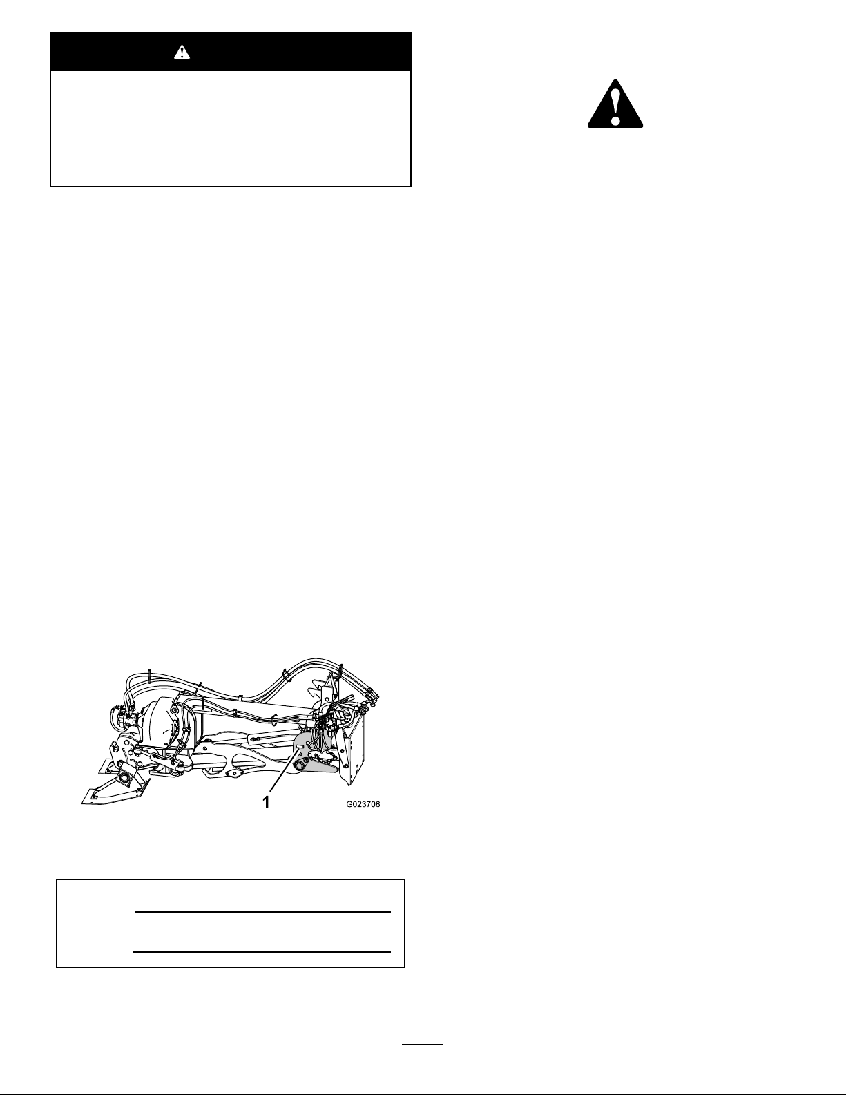
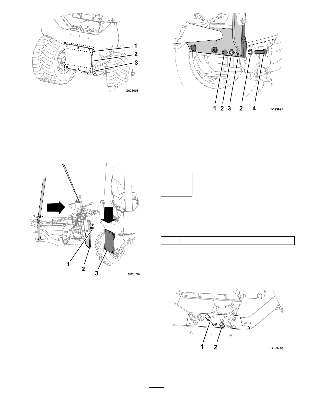
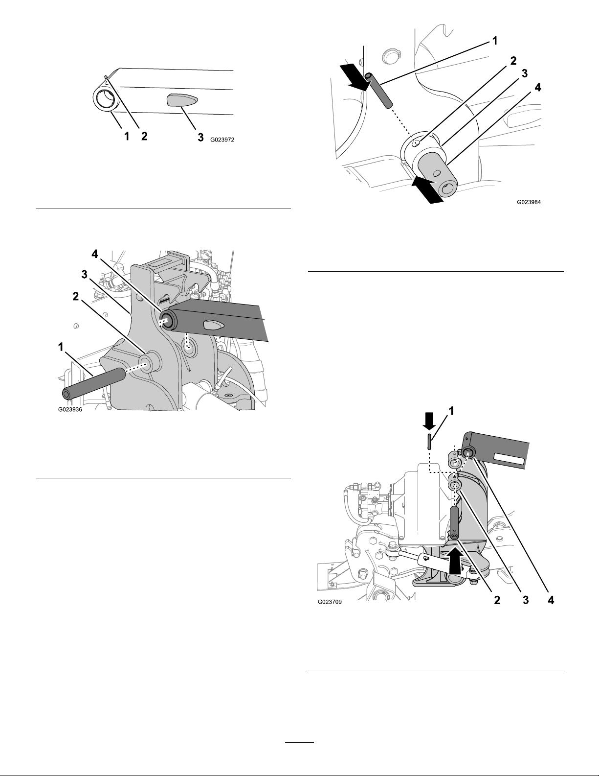
Figure1
1.Locationofthemodelandserialnumberplate
ModelNo.
SerialNo.
Thismanualidentiespotentialhazardsandhassafety
messagesidentiedbythesafetyalertsymbol(Figure2),
©2014—TheToro®Company
8111LyndaleAvenueSouth
Bloomington,MN55420
Contactusatwww.Toro.com.
2
PrintedintheUSA
AllRightsReserved
Page 3

Contents
Safety
Safety...........................................................................3
SafetyandInstructionalDecals.................................5
Setup............................................................................6
1PreparingtoInstalltheVibratoryPlow.....................6
2InstallingtheTowerAssemblyontotheTraction
Unit...................................................................7
3ConnectingtheActuatorHoses..............................8
4BleedingtheElevationandSwingActuators..............9
5InstallingtheShaker.............................................11
6ConnectingtheHydraulicHosesforthe
Shaker...............................................................13
7BleedingtheHydraulicSystemoftheVibratory
Plow.................................................................17
Operation....................................................................18
UsingtheTransportLock........................................18
UsingtheVibratoryPlow........................................18
TransportingtheTractionUnitwithaVibratory
Plow.................................................................26
Attachments/Accessories........................................26
OperatingTips......................................................26
Maintenance.................................................................28
RecommendedMaintenanceSchedule(s)......................28
GreasingtheFittings...............................................28
TorquingtheFastenersontheShakerBox..................29
Storage........................................................................30
Troubleshooting...........................................................31
Improperlyusingormaintainingthevibratoryplow
canresultininjury.Toreducethepotentialforinjury,
complywiththesesafetyinstructionsandthoseinthe
tractionunit
thesafetyalertsymbol,whichmeansCaution,Warning,
orDanger—personalsafetyinstruction.Failureto
complywiththeinstructionmayresultinpersonalinjury
ordeath.
Operator’ s Man ual
.Alwayspayattentionto
DANGER
Theremaybeburiedpower,gas,and/ortelephone
linesintheworkarea.Anelectricshockoran
explosionmayoccurifyouplowintoautilityline.
Havethepropertyorworkareamarkedforburied
linesanddonotplowinmarkedareas.Contactyour
localmarkingserviceorutilitycompanytohavethe
propertymarked(forexample,intheUnitedStates,
call811forthenationwidemarkingservice).
DANGER
Theplowbladeandothermovingpartsonthe
machinewillcutorseveryourhands,feet,orother
bodyparts.
•Keephands,feet,andanyotherpartofyour
bodyorclothingawayfromtheplowbladeand
othermovingparts.
•Beforeadjusting,cleaning,repairing,or
inspectingthevibratoryplow,lowertheplowto
theground,stoptheengine,waitforallmoving
partstostop,andremovethekey.
WARNING
Whentheengineisoff,attachmentsintheraised
positioncangraduallylower.Someonebelow
theattachmentmaybepinnedorinjuredbythe
attachmentasitlowers.
Alwayslowertheattachmenttotheground
wheneveryoushutoffthetractionunit.
3
Page 4

WARNING
Whengoingupordownhill,themachinecould
overturniftheheavyendistowardthedownhill
side.Someonemaybepinnedorseriouslyinjured
bythemachineifitoverturns.
Operatethemachineupanddownslopeswith
theheavyendofthemachineuphill.Anattached
vibratoryplowwillmakethebackendofthe
machineheavy.
WARNING
Lightningcancausesevereinjuryordeath.
Iflightningisseenorthunderisheardinthearea,
donotoperatethemachine;seekshelter.
CAUTION
Hydraulicuidescapingunderpressurecan
penetrateskinandcauseinjury.Fluidinjectedinto
theskinmustbesurgicallyremovedwithinafew
hoursbyadoctorfamiliarwiththisformofinjury;
otherwise,gangrenemayresult.
•Keepyourbodyandhandsawayfrompinhole
leaksornozzlesthatejecthigh-pressure
hydraulicuid.
•Usecardboardorpapertondhydraulicleaks;
neveruseyourhands.
CAUTION
Hydraulicttings,hydrauliclines/valves,and
hydraulicuidmaybehotandcanburnyouifyou
touchthem.
•Weargloveswhenmaintaininghydraulic
components.
•Allowthetractionunitandvibratoryplowto
coolbeforetouchinghydrauliccomponents.
•Donottouchhydraulicuidspills.
4
Page 5
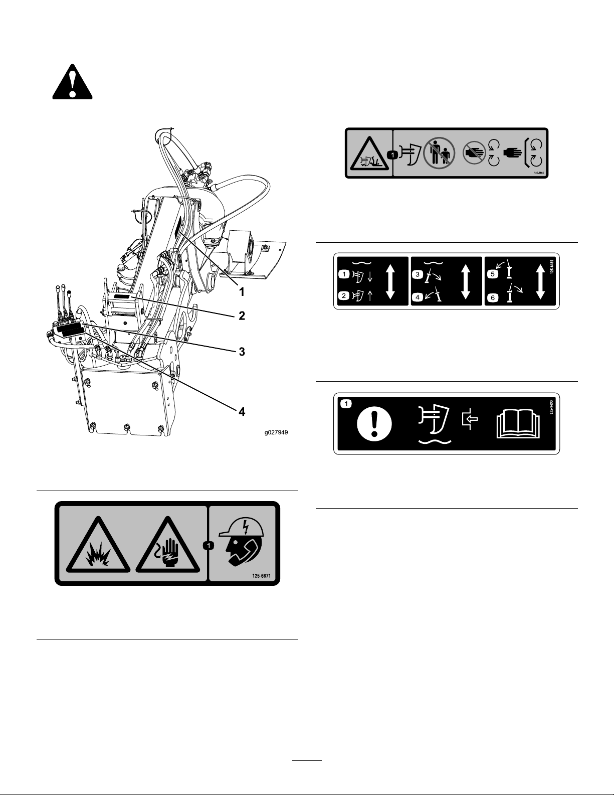
SafetyandInstructionalDecals
Safetydecalsandinstructionsareeasilyvisibletotheoperatorandarelocatednearanyareaofpotential
danger.Replaceanydecalthatisdamagedorlost.
125–6684
1.Cutting/dismembermenthazard,plow—keepbystanders
awayfromtheplow;stayawayfrommovingparts;keepall
guardsandsafetiesinplace.
125-8489
Figure3
1.Decal125-66843.Decal125-8489
2.Decal125-66714.Decal125-8490
125-6671
1.Explosionhazard;electricshockhazard—calllocalutilities
beforedigging.
1.Lowertheplow.
2.Raisetheplow.
3.Swingtheplowtotheright.6.Swingthetrimtotheright.
4.Swingtheplowtotheleft.
5.Swingthetrimtotheleft.
125-8490
1.Attention—forinformationonengagingtheplowoat,read
theOperator'sManual.
5
Page 6

Setup
LooseParts
Usethechartbelowtoverifythatallpartshavebeenshipped.
ProcedureDescription
1
2
3
4
5
6
7
Nopartsrequired
Towerassembly1
Bolt(3/4x2-1/2inch)
Washer(3/4inch)
Locknut(3/4inch)
Fitting,45°(5/8inch)
Nopartsrequired
Shaker
Pin,upperstrut(2x13inch)
Rollpin(5/8x4inch)
Pin,lowerstrut(3x13-5/32inch)
Fitting,45°(5/8inch)
Squarenut
Clampblock
Washer(3/8inch)
Bolt(3/8x2-3/4inch)
Hosesupport3
Bolt(3/8x1-1/2inch)
Cabletie
Nopartsrequired
Qty.
10
10
Use
–
5
5
2
–
1
2
3
1
1
5
2
5
3
7
–
Preparetoinstallthevibratoryplow.
Installthetowerassemblyontothe
tractionunit.
Connecttheactuatorhoses.
Bleedtheelevatorandswingactuators.
Installtheshaker.
Connectthehydraulichosesforthe
shaker.
Bleedthehydraulicsystemofthe
vibratoryplow.
1
PreparingtoInstallthe VibratoryPlow
NoPartsRequired
Procedure
1.Movethetractionunittoalevelsurfaceandlowerall
attachments.
2.Stoptheengine,settheparkingbrake,andremovethe
keyfromtheignitionswitch.
3.Cleantheangeandtherearmountingplateofthe
tractionunit.
4.Ifyouareremovingthetrencherinordertoinstallthe
vibratoryplow ,cleanandcapthehydraulicttingsat
thetractionunitandthetrencher.
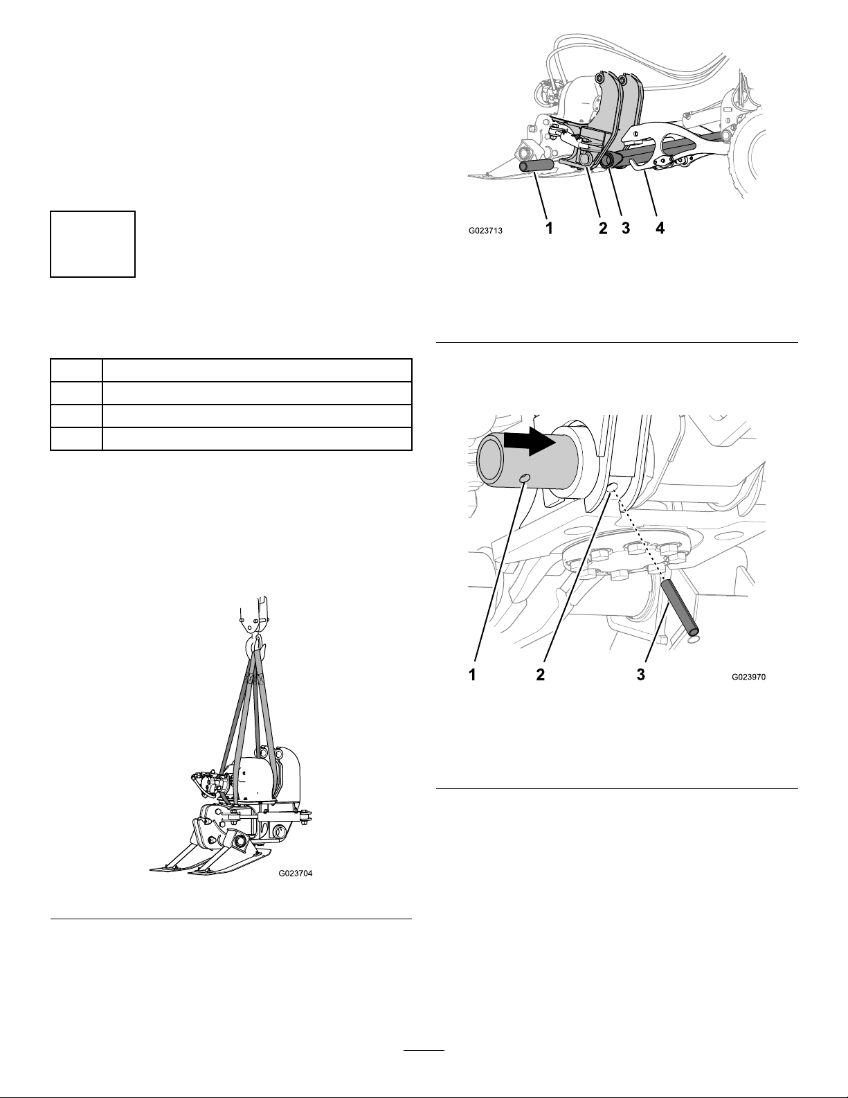
5.Securetheliftingequipmenttothetowerassembly
(Figure4).
Important:Ensurethattheliftingequipmenthas
aliftingcapacityofatleast794kg(1750lb).
6
Page 7
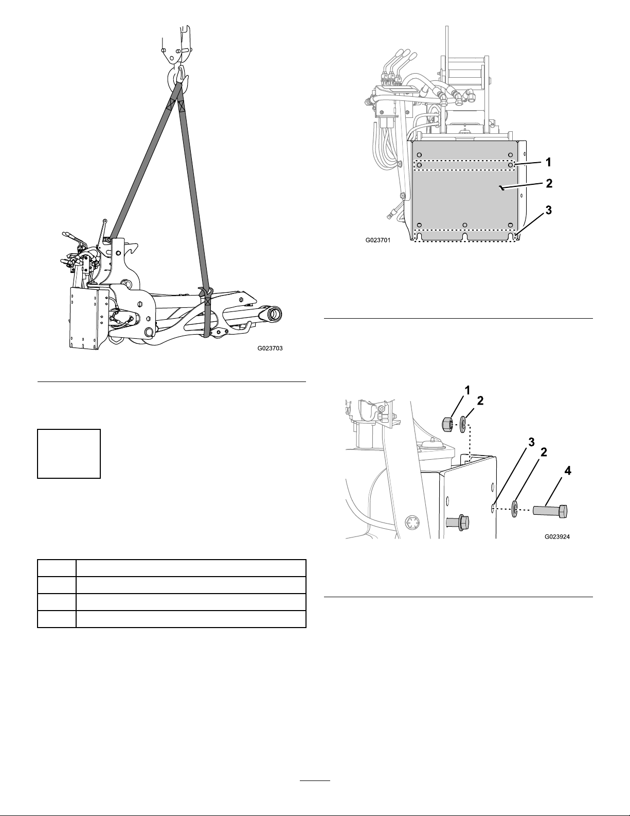
Figure4
6.Raisethetowerassemblyofftheoorasshownin
Figure4.
2
InstallingtheTowerAssembly ontotheTractionUnit
Figure5
Mountingplateonthetowerassembly
1.Row2holes3.Row4slots
2.Mountingplate
2.Insert2bolts(3/4x2-1/2inch)with2washers
throughthefrontsideofthemountingplateonthe
towerassemblyattherow2holesthatyoulocatedin
step1(Figure6).
Partsneededforthisprocedure:
1Towerassembly
5
Bolt(3/4x2-1/2inch)
10
Washer(3/4inch)
5
Locknut(3/4inch)
Procedure
1.Locatetherow2holesandtherow4slotsinthe
mountingplateonthetowerassemblythatyouwill
usetosecuretheattachmentassemblytothetraction
unit(Figure5).
Figure6
1.Locknut3.Row2hole
2.Washer
3.Slipawasherandthreadalocknutontoeachboltatthe
backofthemountingplate(Figure6).
4.Aligntherowofboltsonthetowerassemblysothat
theyareabovetheupperslotsintherearmounting
plateonthetractionunit(Figure7).
7
4.Bolt(3/4x2-1/2inch)
Page 8
3
Figure7
Rearmountingplateonthetractionunit
1.Upperslots3.Lowerslots
2.Rearmountingplate
5.Lowerthetowerassemblysothatthewashersand
locknutsareontheforwardsideofthemountingplate
ofthetractionunitandtheboltsareseatedintheslots
(Figure8).
Figure9
1.Locknut3.Mountingplateslot
2.Washer4.Bolt
8.Torquetheboltsandthelocknutsto583to624N-m
(400to460ft-lb).
9.Lowerandremovetheliftingequipment.
3
ConnectingtheActuator Hoses
Partsneededforthisprocedure:
2
Fitting,45°(5/8inch)
PreparingtoInstallthe
Control-ManifoldHoses
Figure8
1.Boltandwasher3.Rearmountingplateon
thetractionunit
2.Mountingplateonthe
towerassembly
6.Tightentheboltsandthelocknutsbyhand.
7.Installthebolts,locknuts,andwashersintothelower
slotsintherearmountingplateofthetractionunitand
therow4slotsinthemountingplateforthetower
assembly(Figure9).
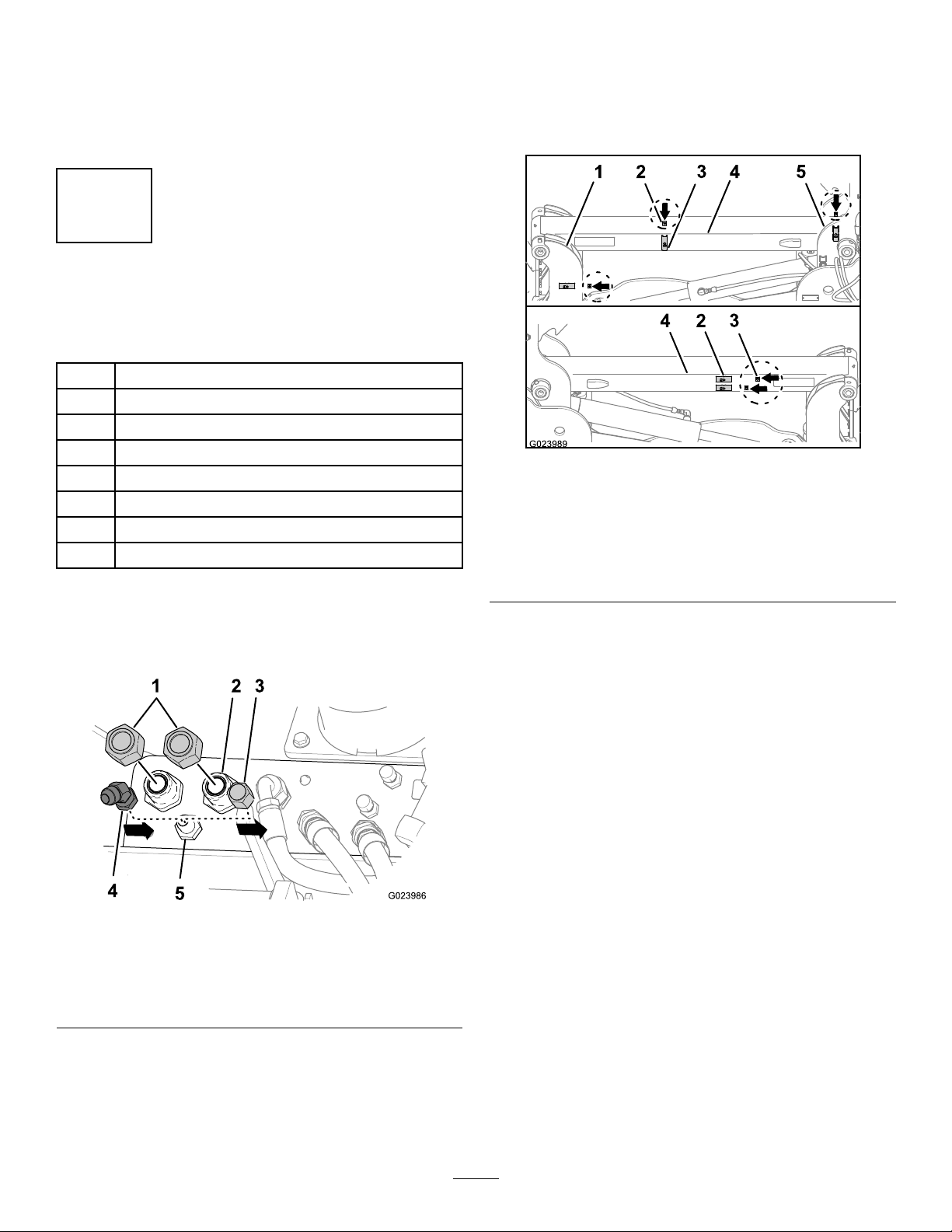
1.Removethehydrauliccapandtheshuntfromthe
bulkheadttings(Figure10).
Figure10
1.Hydraulicshunt2.Hydrauliccap
8
Page 9
2.Installa45°hydraulictting(3/4inch)ontoeach
bulkheadtting(3/4inch)asshowninFigure11,and
tightenthembyhand.
5.Tightenthe90°hosettingatthebulkheadtting
(Figure12)to81to100N-m(60to74ft-lb).
6.Tightenthe2hydraulicttings(45°)atthebulkhead
ttings(Figure12)to81to100N-m(60to74ft-lb).
7.Tightenthe2hydraulichoses(3/4inch)atthe45°
hydraulicttings(Figure12)to81to100N-m(60to
74ft-lb).
Note:Use2wrencheswhentighteningthettingsto
preventtwistingthehoses,whichcouldcausethehose
connectionstoloosenovertime.
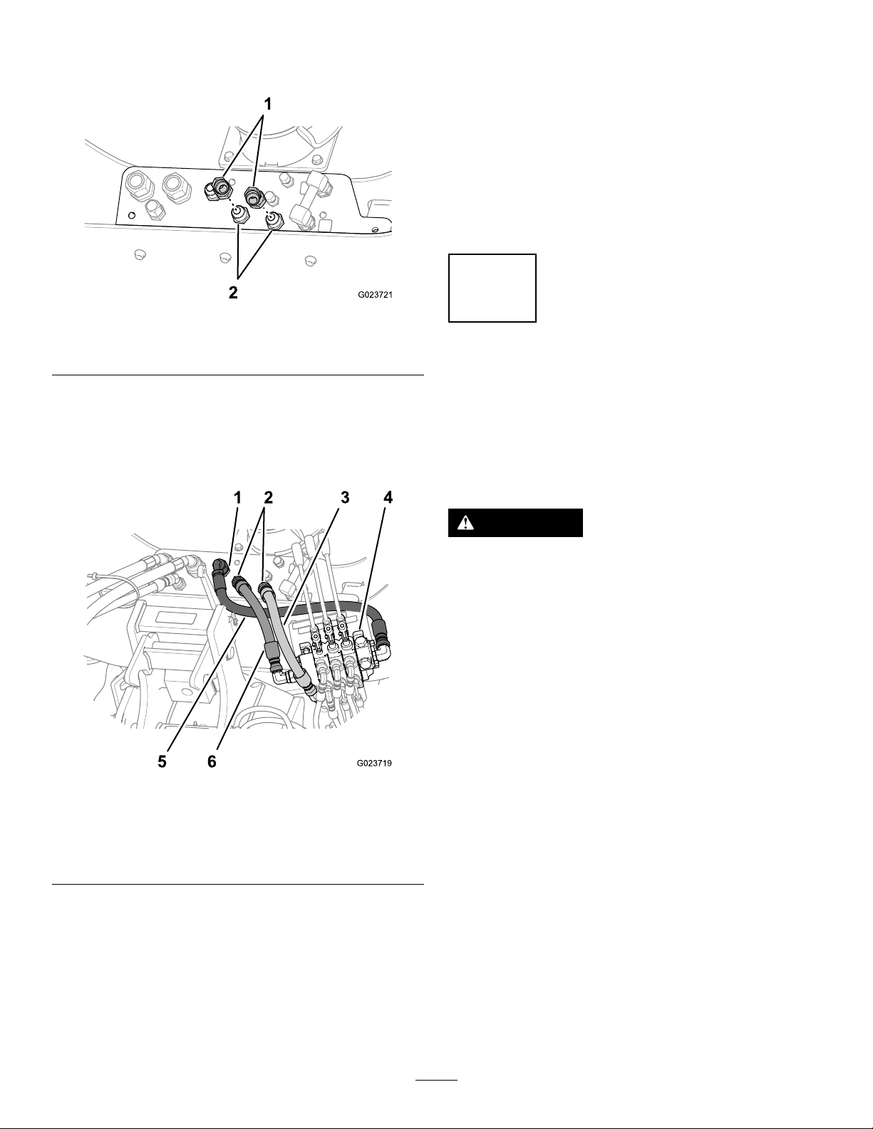
Figure11
1.45°hydraulicttings(3/4
inch)
2.Bulkheadttings(3/4inch)
InstallingtheControl-ManifoldHoses
1.Atthecontrolmanifold,removetheplugsfromthe
freeendsofthe15-1/2-inchhose,the21-inchhose,
andthe26-inchhose(Figure12).
4
BleedingtheElevationand SwingActuators
NoPartsRequired
PreparingtoBleedtheHydraulic
System
WARNING
Operatingthehydraulicsystemofthemachine
withoutplugsorcapsonthehydrauliclines,orwith
merelyplasticplugsorcapssealingthehydraulic
lines,canresultininjuryfromhydraulicuid
discharge.
Installandtightenthesteelplugsandcapson
alltheopenhydrauliclinesbeforeoperatingthe
hydraulicsystem.
Figure12
1.Bulkheadtting(3/4inch)4.Controlmanifold
2.45°hydraulictting(3/4
inch)
3.Hose(5/8x21inch)6.Hose(5/8x15-1/2inch)
2.Connectthe90°ttingofthehose(3/4x26inch)to
the3/4-inchbulkheadtting(Figure12).
3.Connectthe3/4-inchttingofthehose(5/8x15-1/2
inch)totheinboard45°hydraulictting(Figure12)
thatyouinstalledinstep2of(page).
4.Connectthe3/4-inchttingofthehose(5/8x21
inch)totheoutboard45°hydraulictting(Figure12)
thatyouinstalledinstep2of(page).
5.Hose(3/4x26inch)
Important:Performthebleedingproceduresforthe
hydraulicsystemofthevibratoryplowfromtheoperator
seatofthetractionunit.
1.Ensurethatthesteelplugsareinstalledandtightened
inthefreeendsofthetrim-actuatorhose(3/8x98
inch)andthetrim-actuatorhose(3/8x103inch);refer
toFigure13.
9
Page 10
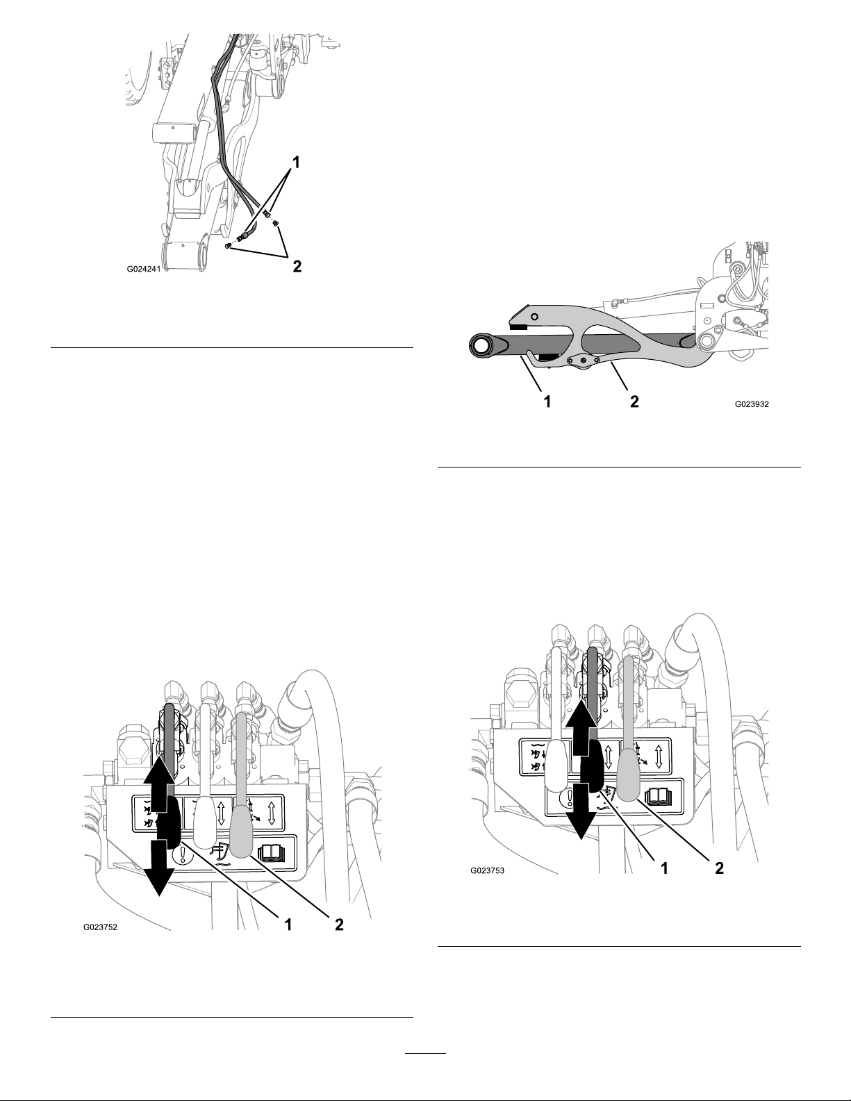
Figure13
2.Slowlylowerthetowerassemblybypushingthe
elevationcontrolleverdown(Figure14).
Note:Donotallowthecradleandthelowerstrutto
striketheground.Movetheelevationcontrolleverto
theNeutralpositionbeforeloweringtheplowtothe
ground.
3.Cyclethetowerassemblyupanddownuntilthetower
movessmoothlyinbothdirections(Figure14).
4.Movethetowerupordownuntilthelowerstrutand
thecradlearelevel(Figure15).
1.Trim-actuatorhose
2.Hydraulicplug,37°steel
(3/8inch)
2.Ensurethattheareasurroundingthevibratoryplowis
clearofallpeopleandobjects.
3.Settheparkingbrakeandmovethecontrolsofthe
tractionunittotheNeutralposition;refertothe
Operator’sManualforthetractionunit.
4.Startthetractionunitandsetthethrottleontheengine
toapproximatelythe1/4throttleposition;refertothe
Operator’sManualforthetractionunit.
BleedingtheElevationActuator
Important:Donotmovetheleverforthetrim-actuator
control!Otherwise,hydraulicuidmayescapethrough
unsecuredttings,possiblycausinginjurytobystanders.
1.Slowlyraisethetowerassemblybyraisingtheelevation
controllever(Figure14).
Figure15
1.Lowerstrut
2.Cradle
BleedingtheSwingActuators
1.Slowlyswingthetowerassemblytotheleftbyraising
theswing-controllever(Figure16).
Note:MovetheswinglevertotheNeutralposition
whenthetowerreachesthepositionfarthesttotheleft.
Figure14
1.Elevationcontrollever2.Donotmovethe
trim-actuatorcontrol
lever!
Figure16
1.Swing-controllever
2.Donotmovethe
trim-actuatorcontrol!
2.Slowlyswingthetowerassemblytotherightby
loweringtheswing-controllever(Figure16).
10
Page 11
Note:MovetheswinglevertotheNeutralposition
whenthetowerreachesthepositionfarthesttothe
right.
3.Cycletheplowleftandrightuntilthetowermoves
smoothlyinbothdirections(Figure16).
4.Centerthetowerstraightbehindthetractionunit.
5.Stoptheengineandremovethekeyfromthekey
switch.
5
InstallingtheShaker
Partsneededforthisprocedure:
1
Shaker
2
Pin,upperstrut(2x13inch)
3
Rollpin(5/8x4inch)
1
Pin,lowerstrut(3x13-5/32inch)
Figure18
1.Lower-strutpin(3x
13-5/32inch)
2.Lower-mountingpoint
(shakerframe)
4.Aligntheholeinthelower-strutpin(3x13-5/32
inch)withthediagonalholeinthebottomofthe
lower-mountingpointoftheshakerframe(Figure19).
3.Lowerstrut
4.Liftcradle
InstallingtheShakertotheLowerStrut
1.Securetheliftingequipmenttotheshakerassembly
(Figure17).
Important:Ensurethattheliftingequipmenthas
aliftingcapacityofatleast794kg(1750lb).
Figure17
Figure19
1.Hole(strutpin3x13-5/32
inch)
2.Diagonalhole(shaker
frame)
5.Insertthestrutpinthroughthelower-mountingpoints
oftheshakerframeandthelowerstrut(Figure19).
6.Inserttherollpin(5/8x4inch)throughthediagonal
holeinthelower-mountingpointoftheshakerframe
andthestrutpin(Figure19).
3.Rollpin(5/8x4inch)
2.RaisetheshakerofftheoorasshowninFigure17.
3.Aligntheholeinthelower-mountingpointofthe
shakerframetotheholeintheendofthelowerstrut
(Figure18).
InstallingtheUpperStrut
Note:Upperstrutweight:41kg(90lbs)
1.Securetheliftingequipmenttotheupperstrut,
andraisethestrutabovethetowerassemblytothe
horizontalposition.
11
Page 12
2.Alignthecamforthetransportlockforwardand
thegreasettingforthestruttothetopofthestrut
(Figure20).
Figure20
1.Forwardmountingpoint
(upperstrut)
2.Greasetting
3.Transport-lockcam
3.Inserttheforwardmountingpointofthestrutbetween
theupperpivotsoftheswingframe(Figure21).
Figure21
1.Upper-strutpin(2x13
inch)
2.Upperpivot(swingframe)
3.Swingframe
4.Upperstrut
Figure22
1.Rollpin(5/8x4inch)3.Upperpivot(swingframe)
2.Diagonalhole
4.Upper-strutpin(3x
13-5/32inch)
5.Inserttheupper-strutpin(2x13inch)throughthe
horizontalholesintheupperpivotsandtheupperstrut
(Figure22).
6.Inserttherollpin(5/8x4inch)throughthediagonal
holeinthepivotandtheholeintheupper-strutpin
(Figure22).
7.Inserttherearmountingpointoftheupperstrut
betweenthepivotpointsoftheframehornsofthe
shaker(Figure23).
4.Aligntheholeintheupper-strutpin(3x13-5/32inch)
withthediagonalholeintheupperpivotsoftheswing
frame(Figure22).
Figure23
1.Rollpin(5/8x4inch)3.Frame-hornpivot(2)
2.Upper-strutpin(2x13
inch)
4.Upperstrut
8.Aligntheholeinthestrutpinwiththeverticalholein
theframe-hornpivot(Figure23).
12
Page 13
9.Securetheupperstruttotheshakerwiththe
upper-strutpin(2x13inch)asshowninFigure23.
10.Securetheupper-strutpintotheframe-hornpivotwith
therollpin(5/8x4inch)asshowninFigure23.
11.Lowerandremovetheliftingequipment.
6
ConnectingtheHydraulic HosesfortheShaker
Partsneededforthisprocedure:
1
Fitting,45°(5/8inch)
5
Squarenut
2
Clampblock
10
Washer(3/8inch)
5
Bolt(3/8x2-3/4inch)
3Hosesupport
3
Bolt(3/8x1-1/2inch)
7
Cabletie
•Thesideoftherightframehorn
•Therightsideoftheupperstrut
•Therightswing-frameplate
•Theleftsideoftheupperstrut(2)
Figure25
Rightsideshowninuppergure;leftsideshowninlower
gure
1.Right-framehorn
2.Squarenut(3/8inch)5.Rightswing-frameplate
3.Nutretainer
4.Upperstrut
PreparingtoInstalltheShakerHoses
1.Removethe2hydrauliccaps(1inch)and1hydraulic
cap(5/8inch)fromthebulkheadttings(Figure24).
Figure24
1.Caps(1inch)4.45°hydraulictting
2.Bulkheadtting—1inch
(2)
3.Cap(5/8inch)
2.Installthe45°hydraulictting(5/8inch)ontothe
bulkheadtting(5/8inch)andtightenitbyhand
(Figure24).
5.Bulkheadtting(5/8inch)
ConnectingtheCase-DrainHose
1.Onthetractionunit,connectthettingofthe
case-drainhose(5/8x115inch)tothe45°hydraulic
tting(Figure26)thatyouinstalledinstep2of(page).
3.Insertasquarenutintoeachofthenutretainersatthe
followinglocations(seealsoFigure25):
13
Page 14

Figure26
1.Case-drainhose(1/2x
115inch)
2.Bulkheadtting(1/2inch)5.Straighttting(1/2inch)
3.45°hydraulictting
4.Hosetting
onthehydraulicmotor
2.Fromtheendofthecase-drainhosettingattached
tothetractionunit,measurealongthehose165cm
(64-3/4inches),andmarkthelocationbywrappinga
pieceoftapearoundthehose.
3.Connectthettingatthefreeendofthehose(5/8x
115inch)tothestraighttting(5/8inch)atthetopof
thehydraulicmotor(Figure26).
4.Atthetapemarkingthe165cm(64-3/4-inch)location
onthecase-drainhose,temporarilysecurethehose
(Figure27)totheleftsideoftheupperstrutwiththe
clampblocks,theclampbar,bolts(3/8x2-3/4inch),
andwashers(3/8inch).
Note:Alignthecase-drainhoseinthemiddleposition
oftheclampingblock.
Note:Use2washersundertheheadofeachbolt.
Figure27
1.Clamp-blockhalf4.Clampbar
2.Nutretainer
3.Case-drainhose6.Bolt(3/8x2-3/4inch)
5.Washer(3/8inch)
5.Tightenthe45°hydraulicttingandthe2hosettings
(Figure26)to81to100N-m(60to74ft-lb).
Note:Use2wrencheswhentighteningthettingsto
preventtwistingthehoses,whichcouldcausethehose
connectionstoloosenovertime.
ConnectingthePressureHose
1.Atthetractionunit,connectthe45°ttingofthehose
(3/4x118inch)tothe3/4inchbulkheadttingas
showninFigure28.
14
Page 15
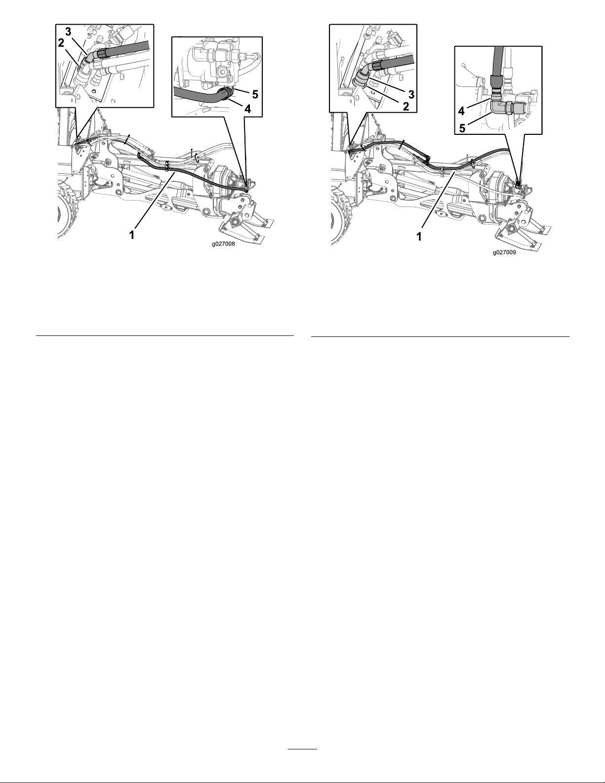
Figure28
1.Hose(3/4x1 18inch)4.Straight-hosetting
2.Bulkheadtting(3/4inch)5.90°hydraulictting(3/4
inch)onthehydraulic
motor
3.45°hosetting
Figure29
1.Hose(3/4x1 18inch)4.Straight-hosetting
2.Bulkheadtting(3/4inch)5.90°tting(3/4inch)onthe
hydraulicmotor
3.45°hosetting
2.Fromtheendofthe45°hosetting,measurealongthe
hose165cm(64-3/4inches),andmarkthelocationby
wrappingapieceoftapearoundthehose.
3.Connectthestraightttingofthehose(3/4x118
inch)tothe90°tting(3/4inch)atthebottomofthe
hydraulicmotor(Figure28).
4.Atthetapemarkingthe165cm(64-3/4-inch)location
onthepressurehose,temporarilysecurethepressure
hosetotheleftsideoftheupperstrutattheclamp
blocks(Figure27).
Note:Alignthepressurehoseinthebottomposition
oftheclampingblock.
5.Tightenthe45°hosettingandthestraight-hose
ttingatthebulkheadttingandthe90°hydraulic
ttingatthehydraulicmotor(Figure28)to116to142
N-m(85to105ft-lb).
Note:Use2wrencheswhentighteningthettingsto
preventtwistingthehoses,whichcouldcausethehose
connectionstoloosenovertime.
ConnectingtheReturnHose
1.Atthetractionunit,connectthe45°ttingofthehose
(3/4x118inch)tothebulkheadtting(3/4inch)as
shownin(Figure29).
2.Fromtheendofthe45°hosetting,measurealong
thehose180cm(71inches),andmarkthelocationby
wrappingapieceoftapearoundthehose.
3.Connectthestraightttingofthehose(3/4x118inch)
tothe90°tting(3/4inch)thatisintheintheT-tting
onthesideofthehydraulicmotor(Figure29).
4.Atthetapemarkingthe180cm(71inch)locationon
thereturnhose,temporarilysecurethereturnhoseto
theleftsideoftheupperstrutwiththeclampblocks
(Figure27).
Note:Alignthereturnhoseinthetoppositionofthe
clampingblock.
5.Removethebolts(3/8x2-3/4inch)securingthe
clampblocks1atatime.
6.Applymedium-strength(serviceremovable),
thread-lockingcompoundtothethreads
7.Threadtheboltsintothenutretainersandtighten
thembyhand.
8.Torquetheboltsto19to24N-m(14to18ft-lb).
9.Tightenthe45°hosettingandthestraight-hose
ttingatthebulkheadttingandthe90°hydraulic
ttingatthehydraulicmotor(Figure29)to116to142
N-m(85to105ft-lb).
Note:Use2wrencheswhentighteningthettingsto
preventtwistingthehoses,whichcouldcausethehose
connectionstoloosenovertime.
10.Installcabletiesaroundthecase-drain,pressure,and
returnhosesatthelocationsshowninFigure30.
15
Page 16

Figure30
1.Cableties
ConnectingtheTrimActuatorHoses
1.Fromtheendofthehosettingconnectedtothe90°
hydraulicttingsatthecontrolmanifold,measurealong
eachhoseandmarkthelocationbywrappingapieceof
tapearoundthehoseatthefollowingmeasurements:
•52cm(21inches)
•130cm(51inches)
•208cm(82inches)
2.Removetheplugfromthefreeendoftheretracthose
(3/8x103inch),andconnectthestraightttingofthe
hosetothe90°ttingintheretractportofthetrim
actuator(Figure31).
withthehosesupport,abolt(3/8x1-1/2inch),and2
washers(3/8inch).
Note:Aligntheretracthoseinthelowerpositionof
thehosesupportandtheextendhoseintheupper
position.
Note:Use2washersundertheheadofthebolt.
Figure32
1.Extendhose(3/8x98
inch)
2.Retracthose(3/8x103
inch)
3.Nutretainer
4.Hosesupport
5.Washer(3/8inch)
6.Bolt(3/8x1-1/2inch)
Figure31
1.90°hydraulictting(retract
port)
2.Trimactuator5.Tapemarker
3.Retracthose
4.Nutretainer
3.Applymedium-strength(serviceremovable),
thread-lockingcompoundtothe3bolts(3/8x1-1/2
inch).
4.Atthetapemarkingthe52cm(21-inch)locationon
theextendandretracthoses,securethehosestothe
nutretainerattherightswing-frameplate(Figure32)
5.Atthetapemarkingthe130cm(51inch)locationon
theextendandretracthoses,securethehosestothe
nutretainerattherightsideoftheupperstrut(Figure
32)withthehosesupport,abolt(3/8x1-1/2inch),
and2washers(3/8inch).
Note:Aligntheretracthoseinthelowerpositionof
thehosesupportandtheextendhoseintheupper
positionofthehosesupport.
Note:Use2washersundertheheadofthebolt.
6.Atthetapemarkingthe208cm(82inch)locationon
theextendandretracthoses,securethehosestothe
nutretainerattheright-framehorn(Figure32)with
thehosesupport,abolt(3/8x1-1/2inch),and2
washers(3/8inch).
Note:Aligntheretracthoseintheforwardposition
ofthehosesupport,thenaligntheextendhoseinthe
rearpositionofthehosesupport.
Note:Use2washersundertheheadofthebolt.
7.Removetheplugfromthefreeendoftheextendhose
(3/8x98inch),andconnectthehosettingtothe90°
16
Page 17

ttingintheextendportofthetrimactuator(Figure
33).
Figure33
1.Extendhose(3/8x98
inch)
2.Retracthose(3/8x103
inch)
8.Tightenthe2hosettingsattheactuator(Figure33)
to37to45N-m(27to33ft-lb).
Note:Use2wrencheswhentighteningthettingsto
preventtwistingthehoses,whichcouldcausethehose
connectionstoloosenovertime.
9.Installcabletiesaroundthetrimhosesatthelocations
showninFigure34.
3.90°hydraulictting(retract
port)
4.90°hydraulictting
(extendport)
7
BleedingtheHydraulicSystem oftheVibratoryPlow
NoPartsRequired
BleedingtheTrimActuator
Important:Performthebleedingproceduresforthe
hydraulicsystemofthevibratoryplowfromtheoperator
seatofthetractionunit.
1.Ensurethattheareasurroundingthevibratoryplowis
clearofallpeopleandobjects.
2.Settheparkingbrakeandmovethecontrolsofthe
tractionunittotheNeutralposition;refertothe
Operator’sManualforthetractionunit.
3.Startthetractionunitandsetthethrottleontheengine
toapproximatelythe1/4throttleposition;refertothe
Operator’sManualforthetractionunit.
4.Slowlyswingthestabilizerforthebladeofthevibratory
plowtotherightbyraisingthetrim-controllever
(Figure35).
Note:Movethetrim-controllevertotheNeutral
positionwhenthestabilizerreachestheposition
farthesttotheright.
1.Cabletie
Figure34
Figure35
1.Trim-controllever
5.Slowlyswingthestabilizertotheleftbyloweringthe
trim-controllever(Figure35).
Note:MovethetrimlevertotheNeutralposition
whenthestabilizerreachesthefullleftposition.
6.Cyclethestabilizerleftandrightuntilthestabilizer
movessmoothlyinbothdirections(Figure35).
17
Page 18

BleedingtheHydraulicMotor
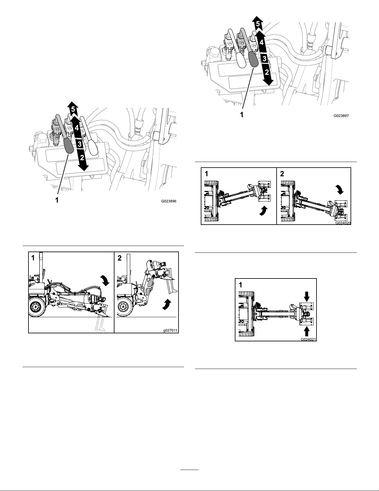
1.Movetheleverfortheshakercontrolrearwardfrom
theNeutralpositionuntilyoufeeltheplowbeginto
vibrate(Figure36).
Figure36
1.Shaker-controllever
2.MovetheleverfortheshakercontroltotheNeutral
position(Figure36).
3.Cycletheleverfortheshakercontrolforwardand
backwardseveraltimesuntiltheresponsetimeforthe
plowtovibrateisconsistent(Figure36).
4.Raisetheplowtothetransportposition,stopthe
engine,andremovethekeyfromthekeyswitch.
Operation
UsingtheTransportLock
UnlockingtheTransportLock
1.Startthetractionunit,settheenginespeedto1/4
throttleormore,andsettheparkingbrake.
2.Slowlyraisethevibratoryplowtoitsfullheight;refer
toUsingtheElevationControl(page19).
3.Pullforwardontheleverforthetransportlock(Figure
37).
Figure37
1.Cam
2.Hook
3.Transport-locklever
4.Lowertheplowuntilthecamontheupperstrutclears
thehookofthetransportlock(Figure37).
LockingtheTransportLock
1.Startthetractionunit,settheenginespeedto1/4
throttleormore,andsettheparkingbrake.
2.Slowlyraisethevibratoryplowtoitshighestposition;
refertoUsingtheElevationControl(page19).
Note:Whenthevibratoryplowisinitshighest
position,thetransportlockautomaticallyengagesthe
camontheupperstrut(Figure37).
Important:Beforemovingthetractionunitor
performingmaintenance,ensurethattheplowisin
itshighestpositionandthatthecamontheupper
strutfullyengagesthehookofthetransportlock.
UsingtheVibratoryPlow
UsingtheOperatorControls
•Fixed-position:Theplowstopsmovingoroatingwhen
youmovethecontrollevertothexedposition.When
youreleasethecontrolleverfromup,down,right,left,
18
Page 19
ortheoatposition,theaffectedcontrolautomatically
returnstothexedposition.
•Floatposition:Whentheleverforthecontrolisinthe
Floatposition,theplowfollowsthecontourofthe
groundwithoutmanuallymovingthecontrollever.
UsingtheElevationControl
•Raisetheplow(Figure38andFigure39).
•Lowertheplow(Figure38andFigure39).
Figure40
1.Swing-controllever4.Swingleft
2.Swingright
3.Fixedposition
5.Floatposition
Figure38
1.Elevation-controllever4.Raise
2.Lower5.Floatposition
3.Fixedposition
Figure39
1.Lowertheplowtothe
Downposition
2.RaisetheplowtotheUp
position
•Floattheplowupordowntofollowthecontourofthe
soil(Figure38).
Figure41
1.Swingtheplowtotheright2.Swingtheplowtotheleft
•Floattheplowleftorrighttofollowthecontourofthe
soil(Figure40andFigure42).
Figure42
1.Floattheplowtotheleftorright
UsingtheTrimControl
UsingtheSwingControl
•Swingtheplowleft(Figure40andFigure41).
•Swingtheplowright(Figure40andFigure41).
•Movethestabilizerleft(Figure43andFigure44).
•Movethestabilizerright(Figure43andFigure44).
19
Page 20

Figure43
1.Trim-controllever3.Fixedposition
2.Trimright
1.Trimthestabilizertothe
left
4.Trimleft
Figure44
2.Trimthestabilizertothe
Figure45
1.Forwardposition3.Reverseposition
2.Neutralposition4.FullReverseposition
InstallingandRemovingtheVibratory
PlowBlade
InstallingthePlowBlade
Note:Thefollowingstepsaregeneralinstructionsfor
installingtheplowblade.Forspecicinstructionson
installingyourblade,refertotheOperator’ sManualfromthe
blademanufacturer.
right
1.Raisethevibratoryplowtothetransportposition;
referto(page).
OperatingtheRear-AttachmentControl
Theshakerfunctionoftheplowiscontrolledbythe
rear-attachmentcontrol,whichislocatedattheright-side
consoleoftheseat.
Important:Youmustbeseatedintheoperatorseat
whenmovingtheleverfortherear-attachmentcontrolto
anypositionotherthanNeutral;otherwise,thetraction
unitwillshutdownin1second.
•TheForwardposition:Movingtheleverofthe
rear-attachmentcontroltotheForwardpositionhasno
effectontheplow(Figure45).
•TheNeutralposition:Movetheleverofthe
rear-attachmentcontroltotheNeutralpositionto
decreaseandstoptheblade-vibrationfunctionofthe
shaker(Figure45).
•TheReverseposition:Movetheleverofthe
rear-attachmentcontroltowardtheReversepositionto
starttheblade-vibrationfunction(Figure45).
•TheFullReverseposition:Movetheleverofthe
rear-attachmentcontroltowardtheFullReverseposition
toincreasethebladevibration-function(Figure45).
Important:Ensurethatthecamontheupper
strutfullyengagesthehookofthetransportlock.
2.Securetheliftingequipmenttothebladeandliftthe
bladetotheverticalposition.
3.Openthebalesofthesafetypins,removethesafety
pinsfromtheblade-mountingpins,andremovethe
blade-mountingpinsfromthestabilizer(Figure46).
Figure46
1.Plowblade
2.Blade-mountingpin4.Mountingslot
3.Safetypin
20
Page 21

4.Centerablade-mountingpinintheupperholeofthe
blade(Figure46).
5.Alignthebladetothestabilizeroftheshaker,andalign
theblade-mountingpintothemountingslotinthe
frameofthestabilizer(Figure46).
6.Lowerthebladeandinsertthepinintotheslot.
Note:Ensurethattheheadofthepinisushwith
thesurfaceofthestabilizer.
7.Alignthelowerholeintheplowbladewiththe
mountingholeinthestabilizer.
8.Installtheblade-mountingpinthroughthemounting
holeinthestabilizerandthroughthelowerholeinthe
plowblade(Figure46).
Note:Ensurethattheheadofthepinisushwith
thesurfaceofthestabilizer.
9.Installthesafetypinsintotheholesintheblademountingpins,andclosethebalesoverthemounting
pins(Figure46).
10.Removetheliftingequipment.
RemovingthePlowBlade
1.Raiseorlowertheplowbladeuntilthebladeisslightly
abovetheground.
2.Secureliftingequipmenttothebladeandlifttheblade
slightly.
3.Openthebalesforthesafetypins,andremovethe
safetypinsfromthemountingpins(Figure46).
4.Removethelowermountingpin(Figure46).
Note:Applyenoughliftingforcewiththelifting
equipmenttokeepthebladefromrotatingasyou
removethelowermountingpin.
5.Raisethebladeuntiltheuppermountingpinclearsthe
mountingslotintheframeofthestabilizer(Figure46).
6.Movetheliftingequipmentandthebladerearwarduntil
theplowbladeclearsthebackofthevibratoryplow .
7.Carefullylowertheplowbladeontoitsside.
8.Removetheliftingequipmentfromtheblade.
Figure47
1.Plowblade
2.Hairpin
2.Pullthegateleverrearwardandrotatethegatedown
(Figure47).
3.Checkthelinksofthechuteforwearandfreedomof
movement;cleanorrepairthelinksbeforeinserting
thecableintothechute.
4.Insertthecableintothecablechute(Figure47).
5.Liftthegateleverupandrotatethegateforward
(Figure47).
6.Installthegatepinthroughtheholeintheretainerof
chute(Figure47).
7.Installthehairpinthroughthegatepin(Figure47).
3.Gatepin
4.Gatelever
PreparingtoUsetheCablePlow
WARNING
Seriousinjuryordeathcanresultfromcontactwith
theploworfromejecteddebrisduringplowing
operation.
InstallingCableintotheCableChute
Thecablechuteisattachedtothebackoftheblade.Some
cablechuteshavereplaceablelinksandotherchutesare
attacheddirectlytotheblade.
Note:Thefollowingaregeneralinstructionsforloading
cableintothecablechute.Forspecicinstructiononusing
yourplowblade,refertotheOperator’ sManualprovidedby
theplowblademanufacturer.
1.Removethehairpinandthegatepinfromthegate
(Figure47).
Makesurethatallpeopleandanimalsareclear
ofthemachineandtheworksitewhileyouare
operatingthevibratoryplow.
WARNING
Vibrationsfromtheplowcancausethewallsofa
trenchtocollapse,causinginjuryordeath.
Neverallowpeopletostandinsideoforadjacent
toanearbytrenchwhileyouareoperatingthe
vibratoryplow .
21
Page 22

WARNING
Vibrationsfromtheplowcancausethesoilofan
overhangorhighbanktofallandcauseinjuryor
death.
Keeppeopleandanimalsawayfromnearby
overhangsandhighbankswhileyouareoperating
thevibratoryplow.
SettingtheShoePositionontheStabilizer
Youcansetthewear-plateshoesforthestabilizerto2
positionsdependingonoperatingconditions,bladeselection,
andyourpreference.
Tochangethepositionofthestabilizershoes,performthe
followingsteps:
1.Raisethevibratoryplowtoanelevationthatallowsyou
toaccessthebottomofthestabilizershoes(Figure48).
PositioningtheSeatforPlowing
Fastentheseatbeltandrotatetheseatclockwise.
Note:Y oumustbeseatedintheoperatorseatbeforemoving
thetractionunit;otherwise,theenginewillstopin1second.
PreparingtheTractionUnit
1.Starttheengineofthetractionunit;refertothe
Operator’sManualofthetractionunit.
2.Settheendingspeedtothe1/2throttlepositionand
allowtheenginetowarmupfor3to5minutes.
3.Ensurethatthevibratoryplowisinthetransport
position;referto(page).
4.Movethetractionunittotheworksite.
PlowingCableandTubing
Important:Youwillreducethelifeofthecableplowif
youoperatetheblade-vibrationfunctionwhiletheblade
isoutoftheground.
LoweringthePlowintotheGround
Figure48
1.Wearplate5.Locknut
2.Flat-headscrews6.Wearplate—inboard
3.Stabilizershoe
4.Washer
position
7.Wearplate—outboard
position
2.Atthewearplate,removethe4setsofat-headscrews,
locknuts,andwashersthatsecuretheplatetothe
stabilizershoe(Figure48).
3.Movethewearplatetoeithertheinboardorthe
outboardpositiontoaligntheholesinthewearplate
withtheholeinthestabilizershoe(Figure48).
4.Securetheplatetothestabilizershoewiththebolts,
locknuts,andwashersthatyouremovedinstep2
(Figure48).
5.Torquethescrewsandnutsto37to45N-m(27to
33ft-lb).
6.Repeatsteps1through5fortheotherwearplateand
stabilizershoe.
Important:Knowthelocationofallunderground
utilitiesbeforeoperatingtheequipmentontheworksite.
1.Releasethecableplowfromthetransportposition;
refertoUnlockingtheTransportLock(page18).
2.Insertthecablethatyouareinstallingattheworksite
intothechute;refertoInstallingCableintotheCable
Chute(page21).
3.Movetheelevationlevertolowertheplowbladeto
thesurfaceofthesoilandanchortheendofthecable
asnecessary.
Important:Donotstarttheblade-vibration
functionoftheplowuntilthebladehasentered
theground.
4.Releasetheparkingbrake;refertotheOperator’sManual
forthetractionunit.
5.Beginloweringthebladeintothegroundbyperforming
thefollowingsteps:
A.Movetheelevationcontroloftheplowtothe
Floatposition;refertoUsingtheElevation
Control(page19).
Note:Slowlylowerthebladeintotheground.
B.EnsurethatthedrivemodeswitchisintheW ork
position(Figure49).
22
Page 23
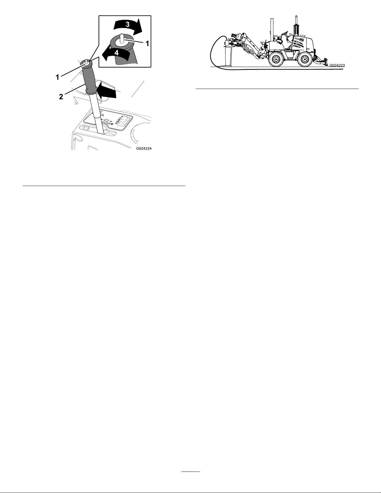
Figure49
1.Drive-modeswitch3.Workposition
2.Traction-controllever4.Transportposition
C.Usingtheutility-tractionlever,movethetraction
unitslowlyforward(Figure49).
Important:Nevermovethetractionunitin
thereversedirectionwiththebladeinthe
ground.
Note:Useonlytheutility-tractionleverto
controltheforwardandreversedirectionsofthe
tractionunitwhileplowing.Thetractionunit
movesforwardorbackwardthroughacontinuous
rangeofspeedsdependingonthepositionofthe
utility-tractionlever.
Thefurtherthatyoupushtheutility-tractionlever
awayfromtheNeutralposition,thefasterthe
tractionunittravels.Theleverstaysinposition
whenyoureleasethelever.Movethelevertothe
Neutralpositiontostopthetractionunitfrom
travelinginforwardorreverse.
6.Oncethebladeenterstheground,beginthe
blade-vibrationfunctionbymovingtherear-attachment
controltotheReverseposition;referto(page).
Note:Ensurethatthechutelinksarehorizontalasthe
bladeenterstheground.
7.When1/4ofthebladeisbelowthesurfaceof
theground(Figure50),graduallyincreasethe
blade-vibrationfunctionbymovingtherear-attachment
controlleverandmovingtheswingcontrolleverinto
theFloatposition.
Figure50
Important:Youwilldamagethecableandthe
chuteifyouforcethebladeintothegroundtoo
fast.Ifyouareplowingintoveryhardground,you
canunintentionallyoverloadthebladeandthereby
under-powertheblade-vibrationfunction.
Note:Movetheutility-tractionlevertowardthe
Neutralpositioniftheplowbladerisesupfromthe
groundwhileyouareplowing.
8.Whenthebladeisdownatfull-plowingdepth,
adjusttherear-attachmentcontrolleversothatthe
blade-vibrationfunctionisfastenoughtoallowthe
tractionunittomaintainthedesiredgroundspeed;
referto(page).
Note:Donotoperatetheblade-vibrationfunction
fasterthannecessarytomaximizethespeed.
Important:Ifthetiresbegintoslipwhileyouare
plowing,reducetheforwardspeedofthetraction
unitbymovingtheutility-tractionlevertowardthe
Neutralposition.
9.Usetheutility-tractionlevertoincreasetheforward
travelspeeduntilthetiresbegintosliporlosetraction
(Figure49).
PlowingAroundanUndergroundObstacle
Performthefollowingstepsifyouencounteranunderground
obstaclewhileplowing:
1.Increasethevibrationspeedbymovingthe
rear-attachmentcontrolleverrearwardwhile
maintainingslightforwardpressureontheplowblade
andtheobstaclewiththetractionunit;referto(page).
2.MovetheswingcontroltotheFloatposition;referto
UsingtheSwingControl(page19).
Note:Thisallowstheobstacletomovearoundthe
sideoftheploworallowstheplowbladetomove
aroundtheobstacle.
PlowingCablefromaBuildingWall
1.Digaholenexttothewallofthebuildingwherethe
cablewillenterthebuilding(Figure51).
23
Page 24

Figure51
Figure52
1.0.6m(24inches)2.Servicehole
3.Plowdirectlytotheserviceholewherethecablesjoins
theserviceconnection(Figure53).
1.Anchorpoint
2.Hole(throughthebuilding
wall)
3.Hole(outsideofbuilding)
2.Drillaholethroughthewallwherethecablewillenter
thebuilding(Figure51).
3.Movethetractionunittoapositionwhereyoucan
lowerthebladeintothehole(Figure51).
4.Threadthecablethroughthechuteoftheblade,and
pushthecablethroughthewall.
5.Lowerthebladeintothehole(Figure51).
6.Anchortheendofthecableinsidethebuilding(Figure
51).
7.Slowlymovethetractionunitforwardandstartthe
blade-vibrationfunctionasthebladeentersthesoil
(Figure51).
8.Asthebladeentersthesoil,slowlystartthe
blade-vibrationfunctionbymovingtherear-attachment
controllevertotheReverseposition;referto(page).
Important:Donotstarttheblade-vibration
functionoftheplowuntilthebladehasentered
theground.
Figure53
1.Loopinthecable
2.Servicehole
4.Beforethebladeenterstheservicehole,stopthe
blade-vibrationfunctionbymovingtherear-attachment
controllevertotheNeutralposition.
5.Movethevibratoryplowbladeacrossthehole(Figure
53).
6.Feedthecabledownthroughthechute,andmakea
loopinthecableatthebottomofthehole(Figure53).
PlowingaServiceConnection
Usethisproceduretoplowtoaserviceconnection,anchor
thecable,andplowtothenextserviceconnectionorend
thecablerun.
1.Ensurethatthestabilizershoesaresettothewide
position;referto(page).
2.Digaserviceholedownwherethecablewilljointhe
serviceconnectiontotheplowingdepthofthecable
run(Figure52)andnowiderthan0.6m(24inch).
Note:Thetractionunitcandriveovera0.6m
(24-inch)hole.
7.Whilefeedingthecableintothechute,movethe
tractionunitforwarduntilthebladeentersthesoilon
theothersideoftheservicehole(Figure53).
8.Asthebladeentersthesoil,slowlystartthe
blade-vibrationfunctionbymovingtherear-attachment
controllevertotheReverseposition;referto(page).
Important:Donotstarttheblade-vibration
functionoftheplowuntilthebladehasentered
theground.
PlowingTurnswithaRadiusLessThan0.9m(36
inches)
1.Atthelocationwherethecablewillturn,digaservice
holedowntotheplowingdepth(Figure52)ofthe
cablerunandnowiderthan0.6m(24inch).
24
Page 25

2.Plowthecabletothehole(Figure54).
PlowingT urnswithaRadiusGreaterThan0.9m(36
inches)
1.Movetheswing-controllevertotheFloatposition;
refertoUsingtheSwingControl(page19).
2.Steerthebladeandthestabilizertotherightbymoving
thetrimcontroltothetrim-rightposition(Figure55);
refertoUsingtheTrimControl(page19).
Note:Allowthebladetotraverseenoughdistanceto
movetothefarthestrightposition.
Figure54
1.Cable-plowrun#12.Cable-plowrun#2
3.Beforethebladeentersthehole,stopthe
blade-vibrationfunctionbymovingtherear-attachment
controllevertotheNeutralposition;referto(page).
4.Movetheswing-controllevertotheFixedposition;
refertoUsingtheSwingControl(page19).
5.Whenthecablechuteofthebladeisinthehole,
performthefollowing:
A.Stopthetractionunit.
B.Removethegatefromthechuteoftheplowblade.
C.Removethecablefromthechute.
D.Carefullyraisethebladeoutofthehole
Note:Donotcutordamagethecablewhileraising
thebladeoutofthehole.
6.Movethetractionunittothepositionthatalignsthe
plowbladewiththenextdirectionforthecablerun
andalongsidetheservicehole(Figure54).
7.Carefullylowerthebladeintotheservicehole.
8.Installthecableintothechuteandinstallthegateto
thechute;refertoInstallingCableintotheCableChute
(page21).
9.Whilefeedingthecableintothechute,movethe
tractionunitforwarduntilthebladeentersthesoilon
thesideoftheservicehole(Figure54).
Figure55
3.Toturnthetractionunittotheright,turnthesteering
wheelclockwisetoturnthefrontwheelstotheright,
andpulltheleverfortherearwheelsteeringcontrolto
theleft(towardyou)toturntherearwheels(Figure56).
Figure56
1.Steeringwheel
2.Rear-wheelsteering
control
4.Usethetrimcontrolofthevibratoryplowtomaintain
orchangethedirectionofthebladeandstabilizer;refer
toUsingtheTrimControl(page19).
10.Asthebladeentersthesoil,slowlystartthe
blade-vibrationfunctionbymovingtherear-attachment
controlleverintheReverseposition.
Important:Donotstarttheblade-vibration
functionoftheplowuntilthebladehasentered
theground.
25
Page 26
RaisingtheBladefromtheGround
DANGER
IftheswingcontrolisintheFloatpositionwhen
thebladeoftheplowisoutoftheground,theplow
mightswinguncontrolledandinjurepeopleor
damageproperty.
5.EnsurethattheswingcontrolisintheFixedposition
beforethebladeoftheplowisoutoftheground;refer
toUsingtheSwingControl(page19).
TransportingtheTractionUnit withaVibratoryPlow
PlacetheswingcontrolintheFixedpositionbefore
thebladeoftheplowisoutoftheground.
Note:Usetheseinstructionsifyouarenotplowingthecable
ortubingintoaserviceholeortrenchattheendoftherun.
Note:Lubricatethecableortubingwhileperformingthis
operation.
1.Slowthetravelspeedofthetractionunitandreduce
thespeedoftheblade-vibrationfunction(Figure57).
Figure57
TransportingtheTractionUnitwitha
VibratoryPlow
1.Removetheplowblade;referto(page).
2.Movethevibratoryplowtothetransportposition;
referto(page).
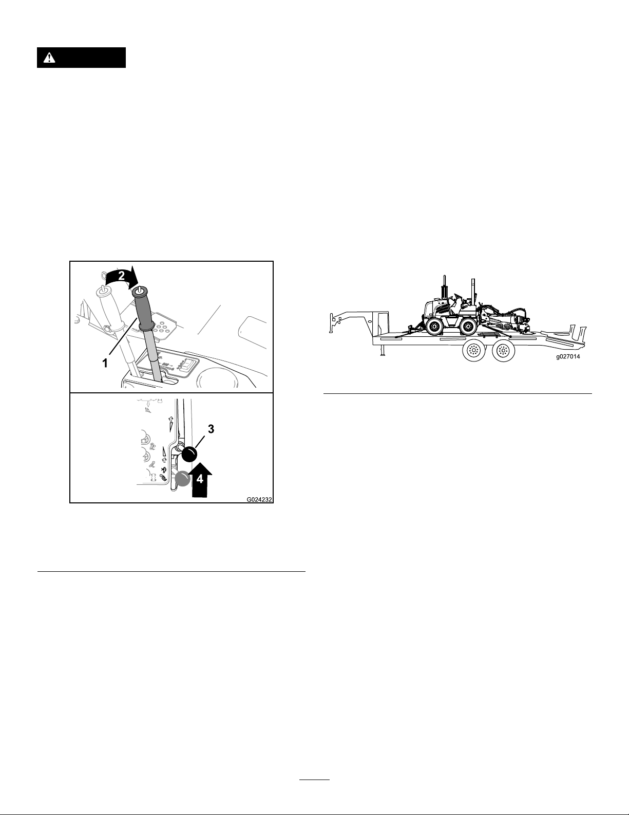
3.Drivethetractionunitontothetransportvehicle.
Note:Positionthetractionunitsothatyoucanlower
theplowontothedeckofthetransportvehicleandthe
decksupportstheplow(Figure58).
Figure58
4.Lowertheplowuntilitisfullysupportedbythe
transportvehicle(Figure58).
5.Movetheplowbladeontothedeckofthetransport
vehicle(Figure58).
6.Bindthetractionunitandtheplowbladetothe
transportvehicle(Figure58).
7.Blockthetiresofthetractionunitatthedeckofthe
transportvehicle(Figure58).
1.Utility-tractionlever3.Rear-attachmentcontrol
lever
2.Slowtravelspeed4.Reducevibrationfunction
2.Ensurethatthecableabovethechutehasadequate
slacktoraisetheplowoutoftheground.
Note:Youcoulddamagethecableatthechuteoutlet
ifthecablehasinsufcientslackabovethevibratory
plow .
3.Movethetractionunitaheadslowlyasyouslowlyraise
theplowbymovingtheelevation-controllevertothe
Raiseposition;refertoUsingtheElevationControl
(page19).
4.Whenthebladeoftheplowisabouthalfwayoutofthe
ground,stoptheblade-vibrationfunctionbymoving
therear-attachmentcontrollevertotheNeutral
position.
Attachments/Accessories
AselectionofToroapprovedattachmentsandaccessoriesis
availableforusewiththemachinetoenhanceandexpand
itscapabilities.ContactyourAuthorizedServiceDealeror
Distributororgotowww .T oro.comforalistofallapproved
attachmentsandaccessories.
OperatingTips
•OperatetheplowwiththeelevationcontrolintheFloat
position;otherwise,excessvibrationwillbetransmitted
tothetractionunitanddamageit.Therefore,youmust
useabladewiththeproperplowingdepthforthejob
beingperformed.
•Duringnormalplowingoperation,oattheswingof
theplowbysettingtheswing-controlleverintheFloat
position.
26
Page 27

•Youcanadjustthehydraulicmotorthatproduces
theblade-vibrationfunctiontoanyspeedinthe
operatingrangeofthemotortoobtainthebestplowing
performance.
•Youcanoptimizetheplowperformanceforasoil
conditionbychangingthetravelspeedofthetractionunit
andthevibrationspeedsettingsatthesametime.Start
withtherear-attachmentcontrolmidwaybetweenthe
NeutralpositionandtheFullReverseposition,andadjust
theforwardtractionspeedwiththeutility-tractionleverto
producea3to10%wheelslip.Movetherear-attachment
controltoadjustthevibrationspeedupordownand
noteiftheperformanceincreasesordecreases.Continue
adjustingthevibrationspeeduntilyouobtainthebest
plowingperformance.
•Generally,plowwithslowvibrationspeedsinlooseor
sandysoiltypes,andplowwithfastvibrationspeedsin
tougherclaysoil.
•Youwillusuallyobtainthefastestplowingspeedswhen
theforward-tractionspeedofthetractionunitandthe
vibrationspeedaresettoprovidetheleastamountof
vibrationattheoperatorseatofthetractionunit.
•Ifthestabilizershoesoftheshakerareinthenarrow
positionandyouarediggingintothegroundtoodeep,set
theshoestothewideposition;referto(page).
•Forthebestperformanceintoughsoilconditions,usea
bladewithanincreasedforwardangleorincreasedtoe
proleatthebottomoftheblade.
•Forthebestperformanceinloose,sandy-soilconditions
orifoatingtheplowoverthetopofthesoilisaproblem,
useabladewithlessforwardangle(nearvertical)and
decreasedtoeprole.
•Forthehighestplowingproductivity,centertheplow
behindthetractionunit.Whentheplowisoffsetfrom
thecenteredposition,thesidedraftofthebladewillcause
thetiresofthetractionunittoslipmoreeasily.
•Whenyouplowwiththeshakerandbladeoffsetfromthe
tractionunit,youcanovercomesidedraftoftheblade
byslightlyturningtherearwheelstowardthesideofthe
tractionunitwheretheplowisoffset.
Note:Turningtherearwheelswhileoffsetplowing
allowsyoutousethefrontwheelsfornormalsteering.
•Iftheplowbladeisoutoftheground,offsettheplow
usingtheswingcontrol.Ifthebladeisintheground,
movetheswingcontroltotheFloatposition,andoffset
theshakerandbladetoeithertherightorleftbyusing
thetrimcontrol.
•Alwaysstopthevibrationbymovingtherear-attachment
controltotheNeutralpositionwhenthebladeisoutof
thegroundorinthegroundandthetractionunitisnot
movingforward.
•Usetheswingcontroltoreducethesidedraftwhen
makingtightturns.ReturntheswingcontroltotheFloat
positionwhenmakingminorchangesindirection.
27
Page 28

Maintenance
RecommendedMaintenanceSchedule(s)
MaintenanceService
Interval
Aftertherst5hours
Beforeeachuseordaily
Every40hours
Note:LookingforanElectricalSchematicorHydraulicSchematicforyourmachine?Downloadafreecopyoftheschematicby
visitingwww .Toro.comandsearchingforyourmachinefromtheManualslinkonthehomepage.
MaintenanceProcedure
•Torquethefastenersontheshakerbox.
•Greasethettings.
•Torquethefastenersontheshakerbox.
GreasingtheFittings
ServiceInterval:Beforeeachuseordaily
Note:Usegeneral-purpose,lithium-basedgrease
1.Cleanthegreasettingswitharag.
2.Connectthegreaseguntothegreasettingandapply
3pumpsofgreasetothetting.
3.Wipeupanyexcessgrease.
Figure59
Figure60
28
Page 29
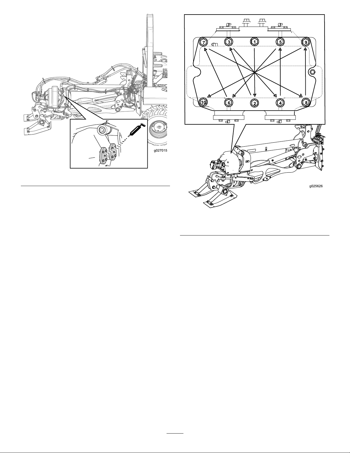
Figure61
TorquingtheFastenersonthe ShakerBox
ServiceInterval:Aftertherst5hours
Every40hours
Torquetheboltsandnutsontheshakerboxto122to136
N-m(90to100ft-lb)inthepatternshowninFigure62.
Figure62
Topviewshownintheinset
29
Page 30

Storage
1.Beforestoringthetractionunit,brushoffthedirtfrom
theattachment.
Note:RefertothetractionunitOperator’sManualfor
storingthetractionunit.
2.Checktheconditionofthehoses,thestabilizershoes,
theplowblade,andthecablechute.Replaceanyworn
ordamagedparts.
3.Checkandtightenallbolts,nuts,andscrews.Repairor
replaceanypartthatisdamagedorworn.
4.Ensurethatallhydrauliccouplersareconnected
togethertopreventcontaminatingthehydraulicsystem.
5.Paintallscratchedorbaremetalsurfaceswithpaint
availablefromanAuthorizedServiceDealer.
6.Storetheattachmentinaclean,drygarageorstorage
area.Coverthevibratoryplowtoprotectitandkeepit
clean.
30
Page 31

Troubleshooting
Problem
Theplowdoesnotvibrate.
Thebladedoesnotplowfastenough.
PossibleCauseCorrectiveAction
1.Ahydraulicttingisnotcompletely
connected.
2.Ahydraulicttingisdamaged.2.Replacethedamagedhydraulictting.
3.Thereisanobstructioninahydraulic
hose.
4.Thedrive-controlcableisdisconnected
orhasfailed.
5.Thehydraulicmotorhasfailed.5.ContactanAuthorizedServiceDealer.
6.Thehydraulicpumphasfailed.6.ContactanAuthorizedServiceDealer.
1.Thereisarestrictioninahydraulic
hose.
2.Thehydraulicsystemistoohot.
3.Thereliefvalveissetbelow
specications.
4.Therunningspeed(rpm)oftheengine
istoolow.
5.Theplowspeed(rpm)isnotatthe
maximumlevel.
1.Checkandtightenallhydraulicttings.
3.Findandremovetheobstruction.
4.Connect,repair,orreplacethe
drive-controlcable.
1.Checkthehosesandrepairany
problemsfound.
2.Shutdownthehydraulicsystemand
allowittocool.
3.ContactanAuthorizedServiceDealer.
4.Increasethethrottlesettingorreduce
thedrive-speedsettingtoallowthe
enginetorecovertoitspeaklevelof
power.
5.Increaseordecreasetheattachment
speed(rpm)tomaximizethedrive
speed.
31
Page 32

TheToroUndergroundWarranty
ALimitedWarranty
Underground
Equipment
ConditionsandProductsCovered
TheToroCompanyanditsafliate,ToroWarrantyCompany,pursuant
toanagreementbetweenthem,jointlywarrantyourToroUnderground
Equipment(“Product”)tobefreefromdefectsinmaterialsorworkmanship.
Whereawarrantableconditionexists,wewillrepairtheProduct
atnocosttoyouincludingdiagnostics,labor,andparts.
ThefollowingwarrantyappliesfromthedatetheProductisdeliveredtothe
originalretailpurchaserorrentalowner.
ProductsWarrantyPeriod
EnginePoweredUnits&FluidMixers
AllSerializedAttachments
RockHammer6months
Engines
1yearor1000operatinghours,
whicheveroccursrst
1year
Throughenginemanufacturers:
2yearsor2000operatinghours,
whicheveroccursrst
InstructionsforObtainingWarrantyService
YouareresponsiblefornotifyingtheUndergroundDealerfromwhomyou
purchasedtheProductassoonasyoubelieveawarrantablecondition
exists.IfyouneedhelplocatingaUndergroundDealer ,orifyouhave
questionsregardingyourwarrantyrightsorresponsibilities,youmay
contactusat:
ToroCustomerCare
ToroWarrantyCompany
811 1LyndaleAvenueSouth
Bloomington,MN55420-1196
TollFreeat855-493-0088(U.S.Customers)
1-952-948-4318(InternationalCustomers)
OwnerResponsibilities
AstheProductowner,youareresponsibleforrequiredmaintenanceand
adjustmentsstatedinyourOperator'sManual.Failuretoperformrequired
maintenanceandadjustmentscanbegroundsfordisallowingawarranty
claim.
ItemsandConditionsNotCovered
Notallproductfailuresormalfunctionsthatoccurduringthewarranty
periodaredefectsinmaterialsorworkmanship.Thiswarrantydoesnot
coverthefollowing:
•Productfailureswhichresultfromtheuseofnon-T ororeplacement
parts,orfrominstallationanduseofadd-on,ormodiednon-Toro
brandedaccessoriesandproducts.Aseparatewarrantymaybe
providedbythemanufactureroftheseitems.
•Productfailureswhichresultfromfailuretoperformrecommended
maintenanceand/oradjustments.Failuretoproperlymaintainyour
ToroproductpertheRecommendedMaintenancelistedinthe
Operator’sManualcanresultinclaimsforwarrantybeingdenied.
•ProductfailureswhichresultfromoperatingtheProductinanabusive,
negligent,orrecklessmanner.
•Partssubjecttoconsumptionthroughuseunlessfoundtobedefective.
Examplesofpartswhichareconsumed,orusedup,duringnormal
Productoperationinclude,butarenotlimitedto:brakes,lters,lights,
bulbs,belts,tracksortires,diggingteeth,diggingbooms,digging,
drive,ortrackchains,trackpads,drivesprockets,idlers,rollers,
blades,cuttingedges,orothergroundengagingcomponents.
•Failurescausedbyoutsideinuence.Conditionsconsideredtobe
outsideinuenceinclude,butarenotlimitedto,weather,storage
practices,contamination,useofunapprovedfuels,coolants,lubricants,
additives,water,orchemicals,etc.
•Failureorperformanceissuesduetotheuseoffuels(e.g.gasoline,
diesel,orbiodiesel)thatdonotconformtotheirrespectiveindustry
standards.
•Normalnoise,vibration,wearandtear ,anddeterioration.
•Normal“wearandtear”includes,butisnotlimitedto,damagetoseats
duetowearorabrasion,wornpaintedsurfaces,scratcheddecals,etc.
•Haulingexpenses,traveltime,mileage,orovertimeassociatedwith
transportingproducttotheauthorizedT orodealer.
Parts
Partsscheduledforreplacementasrequiredmaintenanceinthe
Operator’sManual,arewarrantedfortheperiodoftimeuptothescheduled
replacementtimeforthatpart.Partsreplacedunderthiswarrantyare
coveredforthedurationoftheoriginalproductwarrantyandbecomethe
propertyofT oro.Torowillmakethenaldecisionwhethertorepairany
existingpartorassemblyorreplaceit.Toromayuseremanufacturedparts
forwarrantyrepairs.
MaintenanceisatOwner’sExpense
Enginetune-up,lubrication,cleaningandpolishing,replacementoflters,
coolant,andcompletingrecommendedmaintenancearesomeofthe
normalservicesT oroproductsrequirethatareattheowner’sexpense.
GeneralConditions
RepairbyanAuthorizedToroUndergroundDealerisyoursoleremedy
underthiswarranty.
NeitherTheToroCompanynorToroWarrantyCompanyisliablefor
indirect,incidentalorconsequentialdamagesinconnectionwiththe
useoftheToroProductscoveredbythiswarranty,includingany
costorexpenseofprovidingsubstituteequipmentorserviceduring
reasonableperiodsofmalfunctionornon-usependingcompletion
ofrepairsunderthiswarranty.ExceptfortheEmissionswarranty
referencedbelow,ifapplicable,thereisnootherexpresswarranty.All
impliedwarrantiesofmerchantabilityandtnessforusearelimitedto
thedurationofthisexpresswarranty.
Somestatesdonotallowexclusionsofincidentalorconsequential
damages,orlimitationsonhowlonganimpliedwarrantylasts,sotheabove
exclusionsandlimitationsmaynotapplytoyou.Thiswarrantygivesyou
speciclegalrights,andyoumayalsohaveotherrightswhichvaryfrom
statetostate.
Noteregardingenginewarranty:
TheEmissionsControlSystemonyourProductmaybecoveredby
aseparatewarrantymeetingrequirementsestablishedbytheU.S.
EnvironmentalProtectionAgency(EP A)and/ortheCaliforniaAirResources
Board(CARB).Thehourlimitationssetforthabovedonotapplytothe
EmissionsControlSystemWarranty.RefertotheEngineEmissionControl
WarrantyStatementsuppliedwithyourproductorcontainedintheengine
manufacturer’sdocumentationfordetails.
CountriesOtherthantheUnitedStatesorCanada
CustomerswhohavepurchasedT oroproductsexportedfromtheUnitedStatesorCanadashouldcontacttheirT oroDistributor(Dealer)toobtain
guaranteepoliciesforyourcountry ,province,orstate.IfforanyreasonyouaredissatisedwithyourUndergroundDealer’sserviceorhavedifculty
obtainingguaranteeinformation,contacttheToroimporter.
AustralianConsumerLaw:AustraliancustomerswillnddetailsrelatingtotheAustralianConsumerLaweitherinsidetheboxoratyourlocalT oro
Dealer.
374-0292RevB
 Loading...