

Page 1
FormNo.3386-896RevA
g019008
ProSneak360VibratoryPlow
ModelNo.25400—SerialNo.314000001andUp
ModelNo.25400A—SerialNo.314000001andUp
ModelNo.25400C—SerialNo.314000001andUp
Registeratwww.T oro.com.
OriginalInstructions(EN)
*3386-896*A
Page 2
WARNING
g018963
1
Introduction
CALIFORNIA
Proposition65Warning
Thisproductcontainsachemicalorchemicals
knowntotheStateofCaliforniatocausecancer,
birthdefects,orreproductiveharm.
Dieselengineexhaustandsomeofits
constituentsareknowntotheStateof
Californiatocausecancer,birthdefects,
andotherreproductiveharm.
Becauseinsomeareastherearelocal,state,orfederal
regulationsrequiringthatasparkarresterbeusedonthe
engineofthismachine,asparkarresterisavailableas
anoption.Ifyourequireasparkarrester,contactyour
AuthorizedToroServiceDealer.
GenuineT orosparkarrestersareapprovedbytheUSDA
ForestryService.
Important:ItisaviolationofCaliforniaPublic
ResourceCodeSection4442touseoroperatetheengine
onanyforest-covered,brush-covered,orgrass-covered
landwithoutasparkarrestermufermaintainedin
workingorder,ortheengineconstricted,equipped,and
maintainedforthepreventionofre.Otherstatesor
federalareasmayhavesimilarlaws.
Readthisinformationcarefullytolearnhowtooperateand
maintainyourproductproperlyandtoavoidinjuryand
productdamage.Youareresponsibleforoperatingthe
productproperlyandsafely.
YoumaycontactTorodirectlyatwww .Toro.comforproduct
andaccessoryinformation,helpndingadealer,ortoregister
yourproduct.
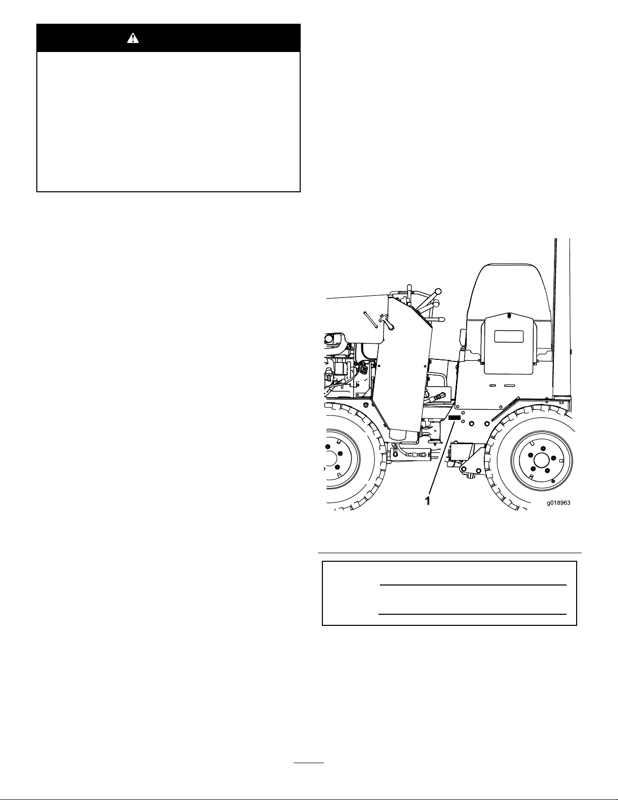
Wheneveryouneedservice,genuineT oroparts,oradditional
information,contactanAuthorizedServiceDealerorToro
CustomerServiceandhavethemodelandserialnumbersof
yourproductready.Figure1identiesthelocationofthe
modelandserialnumbersontheproduct.Writethenumbers
inthespaceprovided.
Theenclosed
Engine Owner's Man ual
issuppliedfor
informationregardingtheUSEnvironmentalProtection
Agency(EPA)andtheCaliforniaEmissionControl
Regulationofemissionsystems,maintenance,and
warranty.Replacementsmaybeorderedthroughthe
enginemanufacturer.
Figure1
1.Modelandserialnumberlocation
ModelNo.
SerialNo.
©2014—TheToro®Company
8111LyndaleAvenueSouth
Bloomington,MN55420
Contactusatwww.Toro.com.
2
PrintedintheUSA.
AllRightsReserved
Page 3

Thismanualidentiespotentialhazardsandhassafety
messagesidentiedbythesafetyalertsymbol(Figure2),
whichsignalsahazardthatmaycauseseriousinjuryordeath
ifyoudonotfollowtherecommendedprecautions.
Figure2
1.Safetyalertsymbol
Thismanualuses2wordstohighlightinformation.
Importantcallsattentiontospecialmechanicalinformation
andNoteemphasizesgeneralinformationworthyofspecial
attention.
Contents
Safety...........................................................................4
SafeOperatingPractices...........................................4
SafetyandInstructionalDecals.................................7
ProductOverview.........................................................12
Controls...............................................................12
Specications........................................................14
Attachments/Accessories........................................14
Operation....................................................................14
AddingFuel...........................................................14
FillingtheFuelTank...............................................15
StartingandStoppingtheEngine..............................15
OperatingtheVibratoryPlow..................................16
RotatingtheWheels................................................17
TransportingtheMachine........................................18
Maintenance.................................................................19
RecommendedMaintenanceSchedule(s)......................19
PremaintenanceProcedures........................................20
OpeningtheHood.................................................20
Lubrication...............................................................20
GreasingtheMachine.............................................20
EngineMaintenance..................................................21
ServicingtheAirCleaner.........................................21
ServicingtheEngineOil..........................................22
FuelSystemMaintenance...........................................24
BleedingtheFuelSystem.........................................24
CheckingtheFuelLinesandConnections..................24
DrainingtheFuelFilter/WaterSeparator...................25
ReplacingtheFuelFilterCanister..............................25
DrainingtheFuelTank...........................................25
ElectricalSystemMaintenance....................................25
ServicingtheBattery...............................................25
DriveSystemMaintenance.........................................27
CheckingtheTirePressure......................................27
CheckingtheTiresandLugNuts.............................27
ServicingtheTransmissionandAxles........................27
CoolingSystemMaintenance......................................29
ServicingtheCoolingSystem...................................29
BeltMaintenance......................................................30
CheckingtheAlternatorDriveBeltTension...............30
ReplacingtheDriveBelt..........................................30
ControlsSystemMaintenance.....................................30
CheckingtheParkingBrake.....................................30
AdjustingtheCreepControlLinkage........................30
AdjustingtheTractionDriveforNeutral....................31
HydraulicSystemMaintenance....................................31
ServicingtheHydraulicSystem.................................31
ROPSMaintenance....................................................34
CheckingandServicingtheROPS.............................34
Cleaning...................................................................35
RemovingDebrisfromtheMachine..........................35
CleaningtheChassis...............................................35
Storage........................................................................35
Troubleshooting...........................................................36
3
Page 4

Safety
Improperuseormaintenancebytheoperatororowner
canresultininjury.Toreducethepotentialforinjury,
complywiththesesafetyinstructionsandalways
payattentiontothesafetyalertsymbol,which
means:
instruction.Failuretocomplywiththeinstructionmay
resultinpersonalinjuryordeath.
SafeOperatingPractices
Thisproductiscapableofamputatinghandsandfeet.Always
followallsafetyinstructionstoavoidseriousinjuryordeath.
Engineexhaustcontainscarbonmonoxide,an
odorless,deadlypoisonthatcankillyou.
Donotruntheengineindoorsorinanenclosed
area.
Training
•ReadtheOperator'sManualandothertrainingmaterial.If
•Becomefamiliarwiththesafeoperationoftheequipment,
•Alloperatorsandmechanicsshouldbetrained.The
•Neverletchildrenoruntrainedpeopleoperateorservice
•Theowner/usercanpreventandisresponsiblefor
Preparation
•Evaluatetheterraintodeterminewhataccessoriesand
•Wearappropriateclothingincludinghardhat,safety
•Inspecttheareawheretheequipmentistobeusedand
•Useextracarewhenhandlingfuels.Theyareammable
Caution
,
W ar ning
,or
Danger
—personalsafety
WARNING
theoperator(s)ormechanic(s)cannotreadEnglish,itis
theowner'sresponsibilitytoexplainthismaterialtothem.
operatorcontrols,andsafetysigns.
ownerisresponsiblefortrainingtheusers.
theequipment.Localregulationsmayrestricttheageof
theoperator.
accidentsorinjuriesoccurringtopeople,ordamageto
property.
attachmentsareneededtoproperlyandsafelyperform
thejob.Onlyuseaccessoriesandattachmentsapproved
bythemanufacturer.
glasses,longpants,safetyshoes,reectorvests,
respirators,andhearingprotection.Longhair,loose
clothingorjewelrymaygettangledinmovingparts.
removeallobjectssuchasrocks,toys,andwirewhichcan
bethrownbythemachine.
andvaporsareexplosive.
–Useonlyanapprovedcontainer
–Neverremovethefuelcaporaddfuelwiththeengine
running.Allowtheenginetocoolbeforerefueling.
Donotsmoke.
–Neverrefuelordrainthemachineindoors.
–Knowthehandsignalsusedonyourjob.Followthe
instructionsoftheagmen,signals,etc.
•Checkthattheoperator'spresencecontrols,safety
switches,andshieldsareattachedandfunctioning
properly.Donotoperateunlesstheyarefunctioning
properly.
Operation
•Beforedigging,havetheareamarkedfor
undergroundutilities,anddonotdiginmarked
areas.
•Neverrunanengineinanenclosedarea.
•Beforestartingeachday,checkthemachineforoiloruid
leaks.Replacealldamaged,loose,wornormissingparts
andfollowthelubricationandmaintenanceprocedures
showninthismanual.
•Onlyoperateingoodlight,keepingawayfromholesand
hiddenhazards.
•Besurealldrivesareinneutralandparkingbrakeis
engagedbeforestartingtheengine.Onlystarttheengine
fromtheoperator'sposition.
•Slowdownanduseextracareonhillsides.Ground
conditionsmayadverselyaffectthestabilityofthe
machine.Usecautionwhenworkingonnewlydisturbed
earth.
•Allowadequatespacewhenturningthisunit.
•Slowdownandusecautionwhenmakingturnsandwhen
changingdirectionsonslopes.
•Neveroperatewithouttheguardssecurelyinplace.Be
sureallinterlocksareattached,adjustedproperly ,and
functioningproperty.
•Donotchangetheenginegovernorsettingoroverspeed
theengine.
•Stoponlevelground,lowerimplements,disengagethe
auxiliaryhydraulics,engageparkingbrake,andshutoff
theenginebeforeleavingtheoperator'spositionforany
reason.
•Keephandsandfeetawayfrommovingattachments.
•Lookbehindanddownbeforebackinguptobesureof
aclearpath.
•Nevercarrypassengersandkeeppetsandbystanders
away.
•Slowdownandusecautionwhenmakingturnsand
crossingroadsandsidewalks.
•Donotoperatethemachineundertheinuenceof
alcoholordrugs.
•Usecarewhenloadingorunloadingthemachineintoa
trailerortruck.
•Usecarewhenapproachingblindcorners,shrubs,trees,
orotherobjectsthatmayobscurevision.
•Readallattachmentmanuals.
4
Page 5

•Ensurethattheareaisclearofotherpeoplebefore
operatingthemachine.Stopthemachineifanyoneenters
thearea.
•Neverleavearunningmachineunattended.Alwaysstop
theengine,settheparkingbrake,andremovethekey
beforeleaving.
•Neverjerkthecontrols;useasteadymotion.
•Watchfortrafcwhenoperatingnearorcrossing
roadways.
•Donottouchpartswhichmaybehotfromoperation.
Allowthemtocoolbeforeattemptingtomaintain,adjust,
orservice.
•Checkforoverheadclearances(i.e.branches,doorways,
electricalwires)beforedrivingunderanyobjectsanddo
notcontactthem.
•Ensurethatyouoperatethemachineinareaswhere
therearenoobstaclesincloseproximitytotheoperator.
Failuretomaintainadequatedistancefromtrees,walls,
andotherbarriersmayresultininjuryasthemachine
backsupduringoperationiftheoperatorisnotattentive
tothesurroundings.Onlyoperatetheunitinareaswhere
thereissufcientclearancefortheoperatortosafely
maneuvertheproduct.
•Neverallowanyoneinthetrenchwhileoperatingthe
machine.
•Locatethepinchpointareasmarkedonthemachineand
attachmentsandkeephandsandfeetawayfromthese
areas.
•Beforeoperatingthemachinewithanattachment,ensure
thattheattachmentisproperlyinstalled.
•Lightningcancausesevereinjuryordeath.Iflightning
isseenorthunderisheardinthearea,donotoperate
themachine;seekshelter.
SlopeOperation
Slopesareamajorfactorrelatedtoloss-of-controland
tip-overaccidents,whichcanresultinsevereinjuryordeath.
Allslopesrequireextracaution.
•Avoidoperatingthismachineonslopes.
•Removeobstaclessuchasrocks,treelimbs,etc.fromthe
workarea.Watchforholes,ruts,orbumps,asuneven
terraincouldoverturnthemachine.Tallgrasscanhide
obstacles.
•UseonlyToro-approvedattachments.Attachmentscan
changethestabilityandtheoperatingcharacteristics
ofthemachine.Warrantymaybevoidedifusedwith
unapprovedattachments.
•Keepallmovementsonslopesslowandgradual.Donot
makesuddenchangesinspeedordirection.
•Avoidstartingorstoppingonaslope.Ifthemachine
losestraction,proceedgradually,straightdowntheslope.
•Avoidturningonslopes.Ifyoumustturn,turnslowly
andkeeptheheavyendofthemachineuphill.
•Donotoperateneardrop-offs,ditches,orembankments.
Themachinecouldsuddenlyturnoverifawheelgoes
overtheedgeofaclifforditch,orifanedgecavesin.
•Donotoperateonwetgrass.Reducedtractioncould
causesliding.
•Donotparkthemachineonahillsideorslopewithout
loweringtheattachmenttotheground,settingtheparking
brake,andchockingthewheels.
•Onlyoperatethemachineonlevelgroundwhenthe
machineisinthenarrowwheelconguration.
RolloverProtectionStructure(ROPS)
System
•BeforeoperatingamachinewithaROPS(rollover
protectionstructure),ensurethattheseatbeltisingood
conditionandissecurelyattachedtothemachine.
•Alwayswearaseatbeltwhenoperatingamachinewith
aROPS.
•InspecttheROPSattheintervalrecommendedinthis
manualorwhentheROPShasbeeninanaccident.
•RepairadamagedROPSusingonlygenuineToro
replacementparts;donotrepairormodifytheROPS.
•Checkcarefullyforoverheadclearances(i.e.branches,
doorways,electricalwires)beforedrivingunderany
objectsanddonotcontactthem.
•DonotremovetheROPSexceptwhenservicingor
replacingit.
•Donotaddweighttothemachinethatexceedsthegross
weightdisplayedontheROPSlabel.
MaintenanceandStorage
•Disengagetheauxiliaryhydraulics,lowertheattachment,
settheparkingbrake,stoptheengine,andremovethe
key.Waitforallmovementtostopbeforeadjusting,
cleaning,orrepairing.
•Cleandebrisfromattachments,drives,mufers,and
enginetohelppreventres.Cleanupoilorfuelspillage.
•Lettheenginecoolbeforestoringanddonotstorenear
ame.
•Donotstorefuelnearamesordrainindoors.
•Parkthemachineonlevelground.Neverallowuntrained
personneltoservicethemachine.
•Usejackstandstosupportcomponentswhenrequired.
•Carefullyreleasepressurefromcomponentswithstored
energy.
•Disconnectthebatterybeforemakinganyrepairs.
Disconnectthenegativeterminalrstandthepositive
last.Reconnectpositiverstandnegativelast.
•Keephandsandfeetawayfrommovingparts.Ifpossible,
donotmakeadjustmentswiththeenginerunning.
5
Page 6

•Chargebatteriesinanopenwellventilatedarea,away
fromsparkandames.Unplugthechargerbefore
connectingordisconnectingitfromthebattery.W ear
protectiveclothinganduseinsulatedtools.
•Keepallpartsingoodworkingconditionandallhardware
tightened.Replaceallwornordamageddecals.
•Keepnutsandboltstight.Keepequipmentingood
condition.
•Nevertamperwithsafetydevices.
•Keepthemachinefreeofgrass,leaves,orotherdebris
build-up.Cleanupoilorfuelspillage.Allowthemachine
tocoolbeforestoring.
•Useextracarewhenhandlingfuels.Theyareammable
andvaporsareexplosive.
–Useonlyanapprovedcontainer.
–Neverremovethefuelcaporaddfuelwhenthe
engineisrunning.Allowtheenginetocoolbefore
refueling.Donotsmoke.
–Neverrefuelthemachineindoors.
–Neverstorethemachineorfuelcontainerinside
wherethereisanopename,suchasnearawater
heaterorfurnace.
–Neverllacontainerwhileitisinsideavehicle,trunk,
pick-upbed,oranysurfaceotherthantheground.
–Keepcontainernozzleincontactwiththetankduring
lling.
•Stopandinspecttheequipmentifyoustrikeanobject.
Makeanynecessaryrepairsbeforerestarting.
•UseonlygenuineTororeplacementpartstoensurethat
originalstandardsaremaintained.
•Batteryacidispoisonousandcancauseburns.Avoid
contactwithskin,eyes,andclothing.Protectyourface,
eyes,andclothingwhenworkingwithabattery.
•Batterygasescanexplode.Keepcigarettes,sparksand
amesawayfromthebattery.
•Keepyourbodyandhandsawayfrompinholeleaks
ornozzlesthatejecthighpressurehydraulicuid.Use
cardboardorpapertondhydraulicleaks;neveruse
yourhands.Hydraulicuidescapingunderpressurecan
penetrateskinandcauseinjuryrequiringsurgerywithina
fewhoursbyaqualiedsurgeonorgangrenemayresult.
6
Page 7
SafetyandInstructionalDecals
Safetydecalsandinstructionsareeasilyvisibletotheoperatorandarelocatednearanyareaofpotential
danger.Replaceanydecalthatisdamagedorlost.
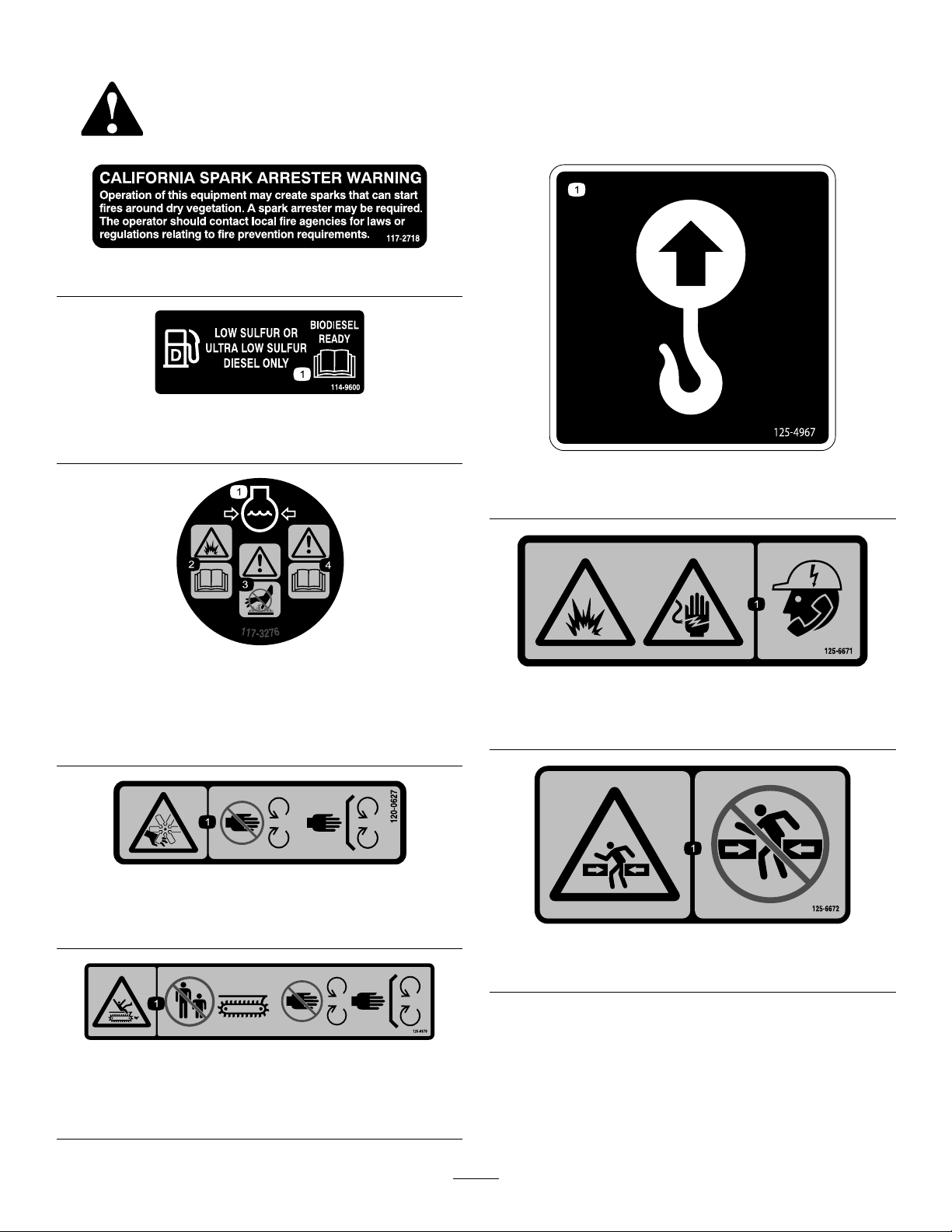
117-2718
114-9600
1.ReadtheOperator'sManual.
125–4967
1.Liftpoint
117-3276
1.Enginecoolantunder
pressure
2.Explosionhazard—read
theOperator'sManual.
3.Warning—donottouchthe
hotsurface.
4.Warning—readthe
Operator'sManual.
120-0627
1.Cutting/dismembermenthazard,fan—stayawayfrom
movingparts,keepallguardsandshieldsinplace.
125–6670
1.Cutting/dismembermenthazard,trencher—keep
bystandersawayfromthetrencher;keepawayfrommoving
parts;keepallguardsandsafetiesinplace.
125-6671
1.Explosionhazard;electricshockhazard—calllocalutilities
beforedigging.
125–6672
1.Crushinghazard—stayawayfromarticulatedjoints.
7
Page 8
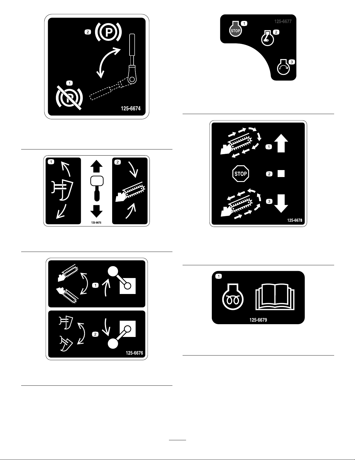
125–6677
1.Engine—stop3.Engine—start
2.Engine—run
125–6674
1.Disengagetheparking
brake.
2.Engagetheparkingbrake.
125–6675
1.Raise/lowertheplow.2.Raise/lowerthetrencher.
1.Turnthetrencher
clockwise.
2.Stopthetrencher .
125–6678
3.Turnthetrencher
counterclockwise.
125–6676
1.Raise/lowerthetrencher.2.Raise/lowertheplow.
125–6679
1.Forinformationonpreheatingtheengine,readthe
Operator’sManual.
8
Page 9
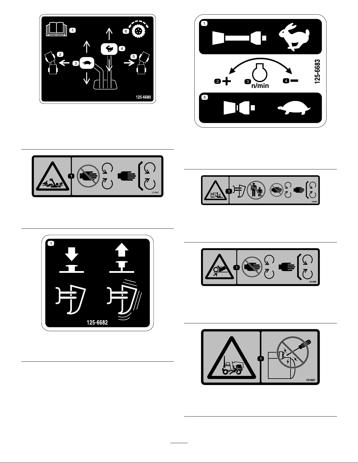
125–6680
1.ReadtheOperator’s
Manual.
2.Turnleft
3.Slow
4.Fast
5.Turnright
6.Tractioncontrol
125–6681
1.Entanglementhazard—keepawayfrommovingparts;keep
allguardsandsafetiesinplace.
125-6683
1.Pulloutforfastestspeed
2.Increasespeed
3.Enginespeed
4.Decreasespeed
5.Pushinforslowestspeed
125–6684
1.Cutting/dismembermenthazard,plow—keepbystanders
awayfromtheplow;stayawayfrommovingparts;keepall
guardsandsafetiesinplace.
1.Pressdowntostopplow
vibration.
125–6686
1.Cutting/dismembermenthazardofhand,trencher—keep
awayfrommovingparts;keepallguardsandsafetiesin
place.
125–6682
2.Pulluptostartplow
vibration.
125–6687
1.Onlystartthemachineusingtheprocedureinthismanual.
Donotattempttostarttheenginewithtools.
9
Page 10
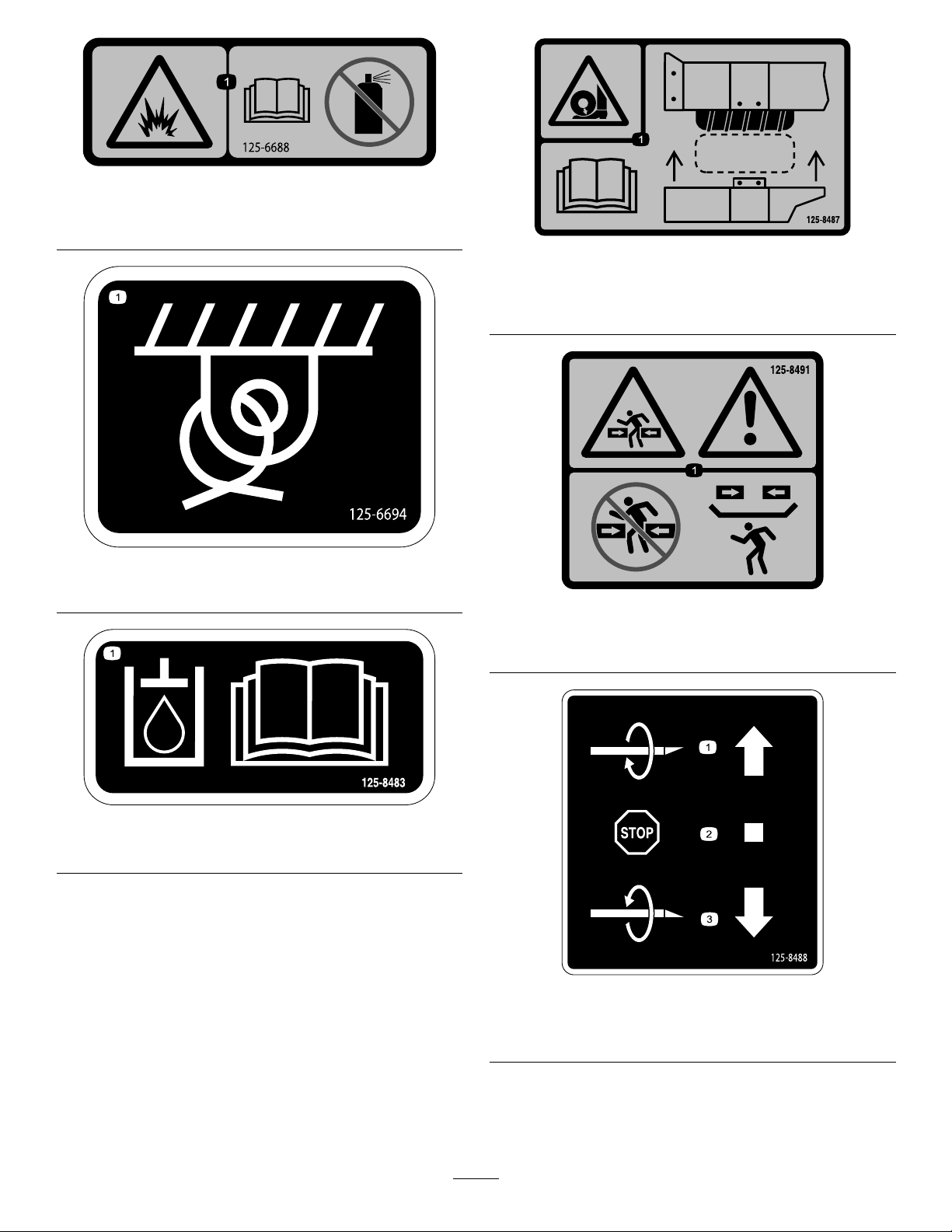
125–6688
1.Explosionhazard—ReadtheOperator’sManual;Donot
usestartinguid.
125–6694
125–8487
1.Crushinghazard,tire—readtheOperator’sManual;the
extensionstepmustbeattachedwhenthetiresareinwide
ordoubledconguration.
1.Tiedownlocation
125–8483
1.Hydraulicuid;readtheOperator’sManual.
125–8491
1.Crushinghazard,warning—keepawayfromarticulated
joints;replacemissingsafetyshields.
125–8488
1.Turnclockwise3.Turncounterclockwise
2.Stoprotation
10
Page 11
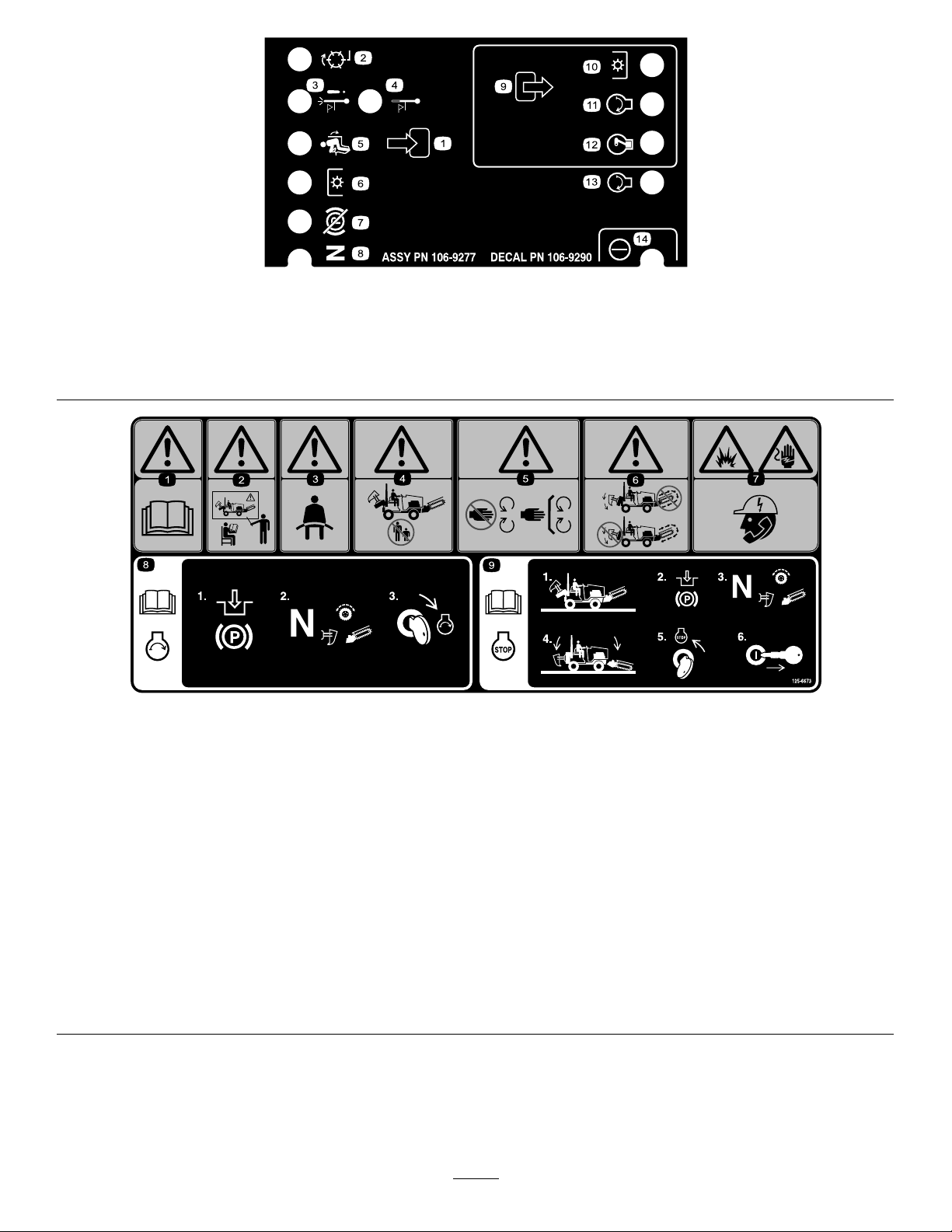
106-9290
1.Inputs5.Inseat
2.Notactive
3.Hightemperatureshutdown
4.Hightemperaturewarning8.Neutral
6.PowerTake-off(PTO)10.PowerTakeOff(PTO)
7.ParkingbrakeOff11.Start
9.Outputs13.Start
12.EnergizetoRun(ETR)
125–6673
1.Warning—readtheOperator’sManual.4.Warning—keepbystandersawayfrom
2.Warning—donotoperatethemachine
unlessyouhavereceivedproper
training.
3.Warning—alwayswearaseatbelt.6.Warning—donotoperatemorethan
themachine.
5.Warning—stayawayfrommoving
parts;keepallguardsandsafetiesin
place.
oneattachmentatatime.
14.Power
7.Explosionhazard;shockhazard—call
thelocalutilitiesbeforedigging
underground.
8.ReadtheOperator’sManualfor
informationonstartingtheengine—1)
Engagetheparkingbrake;2)Putthe
transmissionandallattachmentsin
neutral;3)Turntheignitionkeytothe
enginestartposition.
9.ReadtheOperator’sManualfor
informationonstoppingtheengine—1)
Parkthevehicleonaat,levelsurface;
2)Engagetheparkingbrake;3)Put
thetransmissionandallattachmentsin
neutral;4)Lowertheattachmentsto
theground;5)Turntheignitionkeyto
theenginestopposition;6)Remove
thekeyfromtheignition.
11
Page 12
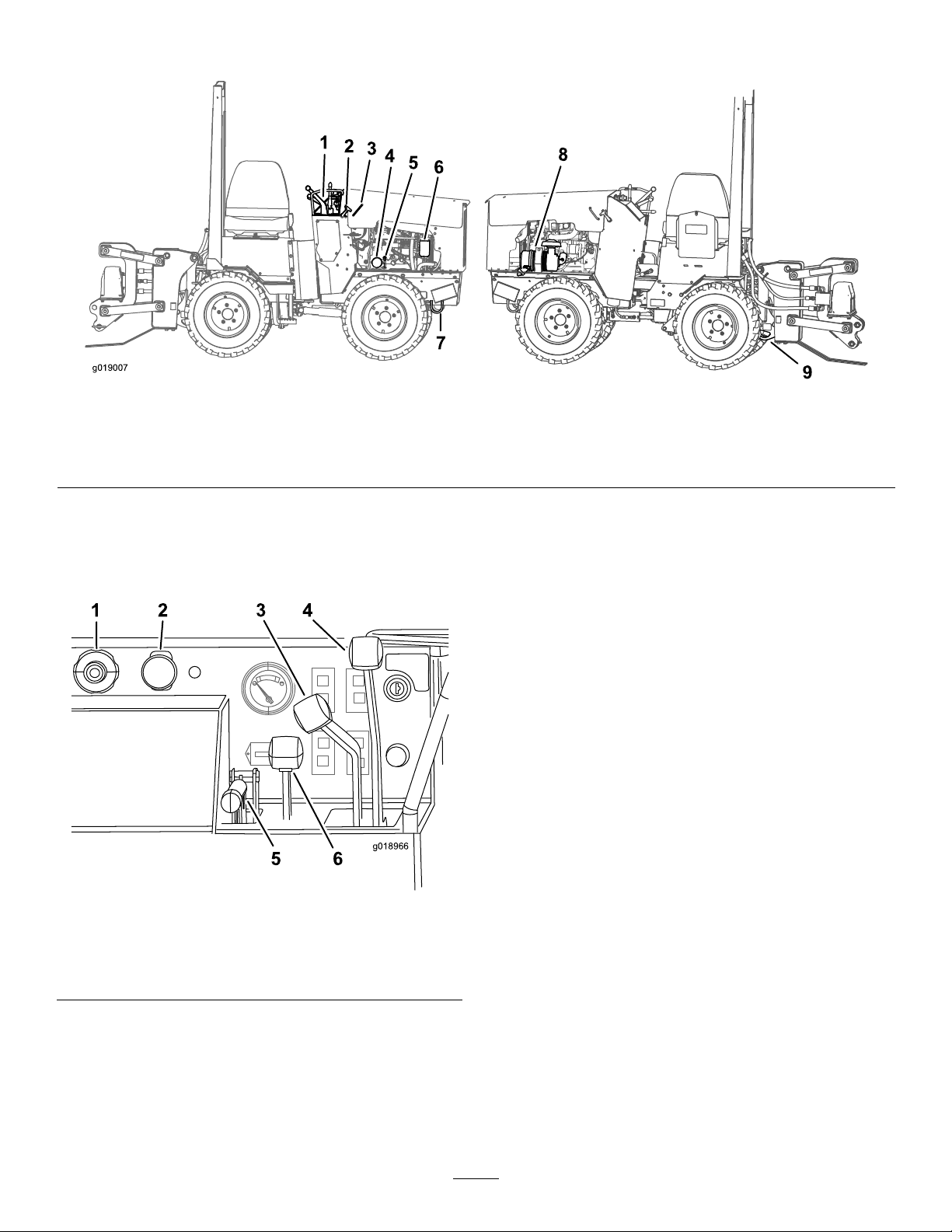
ProductOverview
1
2
3
4
g019007
5
6
7
8
9
1 2 3 4
5 6
g018966
Figure3
1.Controlpanel4.Engine-oillter
2.Hoodlatch5.Engine-oildipstick8.Aircleaner
3.Hoodhandle
Controls
Becomefamiliarwithallthecontrols(Figure4)beforeyou
starttheengineandoperatethemachine.
6.Fuellter
Youcanrotatetheknobtomakesmalladjustmentstothe
enginespeed.Rotatetheknobcounterclockwisetoincrease
enginespeedandclockwisetodecreaseenginespeed.
PTOSwitch
ThePTOswitchcontrolsthevibratoryplow .
Pulltheswitchtostartthevibratoryplow.
Pushtheswitchtostopthevibratoryplow.
CreepControlLever
Thislevercontrolstheforwardandreversedirectionsandthe
machinespeedduringmachineoperation.Thecreepcontrol
leverhasthreepositions:forward,neutral,andreverse.The
machinewillmoveinthedirectionthatyoumovethelever.
Thefartheryoupushorpullthelever,thefasterthemachine
willmove.Theleverwilllockinpositionwhenyourelease
Figure4
1.Throttle4.Directionalcontrollever
2.PTO
3.Creepcontrollever
5.Parkingbrake
6.Attachmentcontrollever
Throttle
Pushthebuttonatthecenteroftheknobandpulltheknob
toincreasetheenginespeed.
Pushthebuttonatthecenteroftheknobandpushtheknob
intodecreaseenginespeed.
thelever.
Thisleverhas5positions:forward,reverse,neutral,right,
andleft.
DirectionControlLever
Thislevercontrolsthedirectionandspeedofthemachine.
Thisleverhas5positions:forward,reverse,neutral,right,
andleft.
Themachinewillmoveinthedirectionthatyoumovethe
lever.Thefartheryoupushorpullthelever,thefasterthe
machinewillmove.
7.Fronttie-downbar
9.Reartie-downbar
12
Page 13

Movethelevertotheneutralpositiontostopthemachine.
2
3
5
g018916
1
4
2
2
4
6
8
g018915
1
3
5
7
KeySwitch
Fromtheneutralposition,pushtheleverslightlyforforward
groundtravel.Pushtheleverfarthertoincreasetheforward
groundspeed.Pulltheleverslightlytodecreasetheforward
groundspeed.
Fromtheneutralposition,pulltheleverslightlyforreverse
groundtravel.Pulltheleverfarthertoincreasethereverse
groundspeed.Pushtheleverslightlytodecreasethereverse
groundspeed.
Whilethemachineisinmotionpushtheleverslightlyleft
orrighttoturnthemachine.
Note:Thedirectionalcontrollevercannotbeusedwhen
usingthecreepcontrollever.
ParkingBrakeLever
Tosettheparkingbrake,pulltheleverupandpushitforward.
Toreleasetheparkingbrake,pulltheleverbackanddown.
AttachmentControlLever
Theattachmentcontrolleverhastwopositions:raiseand
lower.Pullthelevertoraisetheattachment.Pushtheleverto
lowertheattachment.
Thekeyswitch,usedtostartandstoptheengine,has3
positions:on,off,andstart.
Tostarttheengine,rotatethekeytothestartposition.Release
thekeywhenenginestartsanditwillmoveautomaticallyto
theonposition.
Tostoptheengine,rotatethekeytotheoffposition.
PreheatSwitch
Usethisswitchtoenergizetheglowplugsforstartingthe
engineduringcoldweather.
HourMeter
Thehourmeterdisplaysthenumberofhoursofoperation
thathavebeenloggedonthemachine(Figure5).
EngineTemperatureWarningLight
ThislightilluminateswhenthekeyswitchisinTestandthe
engineisnotrunning,orifthereisaproblemwiththeengine
temperature.Ifthelampilluminateswhenengineisrunning,
stoptheengine,removethekey ,andcheckfortheproblem.
RefertoyourEngineOperator’ sManual.
FuelGauge
Thisgaugemeasurestheamountoffuelinthefueltank
(Figure5).
1.Fuelgauge4.Hourmeter
2.Indicatorlights5.Preheatswitch
3.Keyswitch
Figure5
Figure6
1.Enginetemperaturelight5.Engineoilpressurelight
2.Hydraulicoiltemperature
light
3.Engineoillight7.Batterylight
4.Hydraulicoilpressurelight
6.Neutrallight
8.Airlterlight
EngineOilPressureLight
Iftheengineoilpressuregetstoolow,thislightilluminates.If
thishappens,stoptheengineandchecktheoil.Iftheoillevel
islow,addoiland/orlookforpossibleleaks.
AirFilterWarningLight
Thislightilluminateswhenthekeyswitchisintest,orwhen
theengineisrunningandtheairlterisinneedofservice.
Ifthislightilluminateswhentheengineisrunning,stopthe
engine,removethekey ,andservicetheaircleaner.
13
Page 14

NeutralIndicatorLight
Thislightilluminateswhenallcontrolleversareintheneutral
position.
Operation
Note:Determinetheleftandrightsidesofthemachine
fromthenormaloperatingposition.
Specications
Note:Specicationsanddesignaresubjecttochange
withoutnotice.
Width
Width(narrowwheels)91cm(36inches)
Length
Height
Height(narrowwheels)204.2cm(80.4inches)
Weight
Operatingcapacity251kg(553lb)
Tippingcapacity
Wheelbase
Attachments/Accessories
AselectionofToroapprovedattachmentsandaccessoriesis
availableforusewiththemachinetoenhanceandexpand
itscapabilities.ContactyourAuthorizedServiceDealeror
Distributororgotowww .Toro.comforalistofallapproved
attachmentsandaccessories.
Important:UseonlyToroapprovedattachments.
Otherattachmentsmaycreateanunsafeoperating
environmentordamagethemachine.
117cm(46inches)
299.7cm(118inches)
208cm(81.9inches)
1180kg(2601lb)
717kg(1580lb)
122cm(48inches)
Important:Beforeoperating,checkthefuelandoil
level,andremovedebrisfromthemachine.Also,ensure
thattheareaisclearofpeopleanddebris.Y oushould
alsoknowandhavemarkedthelocationsofallutility
lines.
AddingFuel
Useloworultralowsulfurdieselfuel(ULSD)intheengine
ofthismachine.Theuseofotherfuelscancausethelossof
enginepowerandhighfuelconsumption.Thedieselfuel
usedinthismachinemustmeetthespecicationsofD975
ofASTMInternational.Seeyourdieselfueldistributor.The
D975standarddenestwoULSDstandards,GradeNo.
2-DS15(regularULSD)andGradeNo.1-DS15(ahigher
volatilityULSDfuelwithalowergellingtemperaturethan
regularULSD).
Fueltankcapacity:27L(7.1gallons)
Usesummergradedieselfuel(No.2-D)attemperatures
above20°F(-7°C)andwintergrade(No.1-DorNo.
1-D/2-Dblend)belowthattemperature.Useofwintergrade
fuelatlowertemperaturesprovideslowerashpointand
coldowcharacteristicswhichwilleasestartingandreduce
fuellterplugging.
Useofsummergradefuelabove20°F(-7°C)willcontribute
towardlongerfuelpumplifeandincreasedpowercompared
towintergradefuel.
Important:Donotusekeroseneorgasolineinsteadof
dieselfuel.Failuretoobservethiscautionwilldamage
theengine.
WARNING
Fuelisharmfulorfatalifswallowed.Long-term
exposuretovaporscancauseseriousinjuryand
illness.
•Avoidprolongedbreathingofvapors.
•Keepfaceawayfromnozzleandfueltankor
conditioneropening.
•Keepfuelawayfromeyesandskin.
14
Page 15

FillingtheFuelTank
1
g018956
DANGER
Incertainconditions,fuelisextremelyammable
andhighlyexplosive.Areorexplosionfromfuel
canburnyouandothersandcandamageproperty.
•Fillthefueltankoutdoors,inanopenarea,when
theengineiscold.Wipeupanyfuelthatspills.
•Neverllthefueltankinsideanenclosedtrailer.
•Neversmokewhenhandlingfuel,andstayaway
fromanopenameorwherefuelfumesmaybe
ignitedbyaspark.
•Storefuelinanapprovedcontainerandkeepit
outofthereachofchildren.Neverbuymore
thana30-daysupplyoffuel.
1.Lifttheoperatorseattoaccessthefueltank.
2.Removethefueltankcap(Figure7).
•Donotoperatewithoutentireexhaustsystemin
placeandinproperworkingcondition.
DANGER
Incertainconditionsduringfueling,static
electricitycanbereleasedcausingasparkwhich
canignitethefuelvapors.Areorexplosionfrom
fuelcanburnyouandothersandcandamage
property.
•Alwaysplacefuelcontainersonthegroundaway
fromyourvehiclebeforelling.
•Donotllfuelcontainersinsideavehicleoron
atruckortrailerbedbecauseinteriorcarpets
orplastictruckbedlinersmayinsulatethe
containerandslowthelossofanystaticcharge.
•Whenpractical,removeequipmentfromthe
truckortrailerandrefueltheequipmentwithits
wheelsontheground.
•Ifthisisnotpossible,thenrefuelsuchequipment
onatruckortrailerfromaportablecontainer,
ratherthanfromafueldispensernozzle.
•Ifafueldispensernozzlemustbeused,keepthe
nozzleincontactwiththerimofthefueltank
orcontaineropeningatalltimesuntilfuelingis
complete.
Figure7
1.Fuel-tankcap
3.Fillthetanktoabout2.5cm(1inch)belowthetopof
thetank,notthellerneck,withdieselfuel.
4.Installthefuel-tankcap.
StartingandStoppingthe Engine
StartingtheEngine
1.Adjusttheseatandfastentheseatbelt.
2.EnsurethatallofthecontrolleversareintheNeutral
orStopposition.
3.MovethethrottlelevermidwaybetweentheSlowand
Fastpositions.
4.TurntheignitionkeytotheStartposition.Whenthe
enginesstarts,releasethekey.
Important:Donotengagethestarterformore
than10secondsatatime.Iftheenginefailsto
start,allowa30secondcool-downperiodbetween
attempts.Failuretofollowtheseinstructionscan
burnoutthestartermotor.
5.Movethethrottlelevertodesiredsetting.
Important:Iftheengineisrunathighspeeds
whenthehydraulicsystemiscold(i.e.,whenthe
ambientairtemperatureisnearfreezingorlower),
hydraulicsystemdamagecouldoccur.When
startingtheengineincoldconditions,allowthe
enginetoruninthemiddlethrottlepositionfor
2to5minutesbeforemovingthethrottletofast
(rabbit).
15
Page 16

Note:Iftheoutdoortemperatureisbelowfreezing,
1 2 3
g019071
N
SEAT
BELT
4 5 6
storethemachineinagaragetokeepitwarmerand
aidinstarting.
trencher-digging-control,orcreep-controlleversare
movedfromtheNeutralposition.
5.Releasetheparkingbrake.
StoppingtheEngine
1.MovethethrottlelevertotheSlowposition.
2.Loweranyattachmentstotheground.
3.SetallcontrolstotheNeutralorStopposition.
4.Settheparkingbrake.
5.TurntheignitionkeytotheOffposition.
Note:Iftheenginehasbeenworkinghardorishot,
letitidlefor5minutesbeforeturningtheignitionkey
off.Thishelpscooltheenginebeforeitisstopped.In
anemergency,youcanstoptheengineimmediately.
OperatingtheVibratoryPlow
Plowing
1.Starttheengine.
2.Whentheengineiswarm,pullthethrottleleverout
tofullthrottle(Figure8).
Note:Donotstarttheplowvibrationuntiltheblade
tiphasenteredtheground.
6.PullthePTOswitchtostartthecableplowvibration.
7.Slowlylowertheplowbladeintothegroundasthe
machinemovesforward.
8.Usethecreepcontrollevertocontrolthedirectionand
speedofthemachineduringplowing.Themachinewill
moveinthesamedirectionthatyoumovethelever.
Note:Themoreyoupushtheleverfromtheneutral
position,thefasterthemachinewilltravel.Thelever
willstayinthispositionwhenyoureleasethelever.
MovethelevertotheNeutralpositiontostopthe
machinetravel.
9.Usethedirectionorcreepcontrolleverstosteerthe
machinetotheleftorright.
Important:Donotreversethemachinewiththe
plowbladeintheground.
Important:Slowlylifttheplowbladeoutofthe
groundasthemachinemovesforward.
Note:Decreasethemachinespeedifthetiresslip
orthebladeraisesoutofthegroundduringplow
operation.
1.Throttle4.Parkingbrake
2.PTO
3.Attachment-selectorlever
3.Ifthemachineisequippedwithatrencher,movethe
attachmentselectorlevertothecableplowposition
(Figure8).
4.Usetheattachmentcontrollevertolowertheplowto
theground.
10.ReducethespeedofthemachineandpressthePTO
switchtostoptheplowvibrationbeforeraisingthe
bladeoutoftheground.
ChangingthePlowBlade
Theplowbladesareheavy;use2peopletocompletethis
procedure.
1.Parkthemachineonalevelsurface,lowerany
attachments,andstoptheengine.
2.Flipthe2circularsnapringsoverandremovethe
snap-ringpin(Figure9).
Figure8
5.Attachment-controllever
6.Creep-controllever
Note:Theenginewillturnoffin1secondifthe
operatorsseatisemptyandthedirection-control,
16
Page 17

G025774
1
2
3
4
g021986
5
4.Installthenewskidshoesandsecurethemwiththe
g022223
previouslyremovedhardware(Figure10).
RotatingtheWheels
Youcaninstallthewheelstoprovideanarroworawide
overallwidthofmachine.Installthewheelswiththedeep
concavetowardthemachineforoperationintightareasor
theshallowconcavetowardthemachineforwiderstability.
Important:Onlyoperateonlevelgroundwiththe
narrowwheelconguration.
Figure9
1.Snap-ringpin
2.Pin
3.Pullthe2pinsoutoftheblade.
Note:Theplowbladesareheavy.Makesurethat1
personisholdingthebladewhiletheotherpersonis
removingthepins.
4.Placethenewbladeintotheplowbladeassemblyand
secureitwith2pinsand2snap-ringpins.
RemovingandInstallingtheSkidShoes
1.Raisetheplowabout91.4cm(36inches)offthe
ground.
2.Stoptheengineandremovethekey.
3.Removethe4bolts,4nuts,and8washersfromthe
skidshoes(Figure10).
TireSize
23x10.5x12413820
26x12x12820730
PlyRating
Pressure
kPapsi
1.Parkthemachineonalevelsurface,lowerany
attachments,andstoptheengine.
2.Removetherearwheels.
3.Removethestepextensionfromthemachine(Figure
11).
Figure10
1.Nut4.Washer
2.Washer5.Bolt
3.Skidshoes
Figure11
4.Installthewheelsontheoppositesideofthemachine
fromwhicheachwasremoved.
5.Removethefrontwheelsandinstallthemonthe
oppositesideofthemachinefromwhicheachwas
removed.
Note:Besuretokeepthetreadgoinginthesame
direction(seeFigure12).
17
Page 18

g023499
Figure12
1
g018921
1
g018922
Note:Usethereartie-downloop(Figure14)tosecure
themachine.
Figure14
TransportingtheMachine
LoadingtheMachine
Important:Ensurethatthetrailerandrampcan
supportbothyourweightplustheweightofthemachine
withanyattachments.
1.Starttheengine.
2.Movetheattachmentstotransportposition.
3.Securethetrailerhitchtoyourvehicleandputablock
atthefrontandrearofthetrailerwheels.
4.Movethemachineslowlyontothetrailer.
5.Lowertheattachmentsontothetrailerandsetthe
parkingbrake.
6.Stoptheengineandremovethekey.
7.Putblocksatthefrontandrearofeachtireofthe
machine.
8.Fastenthefronttie-downloopsofthemachinetothe
trailer(Figure13).
1.Reartie-downloop
10.Measurethedistancefromthegroundtothehighest
pointofthemachinetodeterminetheclearanceheight.
11.Removetheblocksfromthefrontandrearofthe
trailerwheels.
Important:Aftertransportingthemachineafewmiles,
stopthetruck,ensurethatthetie-downsarestilltight
andthatthemachinehasnotmovedonthetrailer.
UnloadingtheMachine
1.Putablockatthefrontandrearofthemachineand
trailerwheels.
2.Removetheties,thenremovetheblocksfromthe
machine.
3.Starttheengineandreleasetheparkingbrake.Referto
StartingandStoppingtheEngine(page15).
4.Ensurethattheattachmentsareinthetransport
position.
5.Slowlymovethemachineoffofthetrailer.
Figure13
1.Fronttie-downloop
9.Fastentherearofthemachinetothetrailerusing
chainsandabinder.
18
Page 19

Maintenance
Note:Determinetheleftandrightsidesofthemachinefromthenormaloperatingposition.
RecommendedMaintenanceSchedule(s)
MaintenanceService
Interval
Aftertherst25hours
Aftertherst50hours
Aftertherst250hours
Beforeeachuseordaily
Every25hours
Every50hours
Every100hours
MaintenanceProcedure
•Replacethehydrauliclter.
•Changetheengineoilandlter.
•Changethehydraulicuid.
•Greasethemachine(Greaseimmediatelyaftereverywashing).
•Checktheairlterserviceindicatorlight(morefrequentlyifconditionsaredusty
orsandy).
•Checktheengineoillevel.
•Checkthetirepressure.
•Checkthetirepressure.
•Checkthelugnuts.
•Cleantheradiator.
•Checkthecoolingsystem.
•Checkthehydraulicuidlevel.
•Removedebrisfromthemachineandscreens.
•Checkforloosefasteners.
•Removetheaircleanercover,cleanoutanydebris,andchecktheairlterservice
indicatorlight(morefrequentlyifconditionsaredustyorsandy).
•Drainwaterandothercontaminantsfromthefuellter/waterseparator.
•Changetheengineoil.
•Checkthebatteryelectrolytelevel(replacementbatteryonly).
•Checktheaxleoillevels.
•Checkthecoolingsystemhoses.
•Checkthehydrauliclinesforleaks,loosettings,kinkedlines,loosemounting
supports,wear,weather,andchemicaldeterioration.
•Checkfordirtbuild-upinthechassis.
Every200hours
Every250hours
Every400hours
Every500hours
Every1,000hours
Every1,500hours
Every4,000hours
Yearlyorbeforestorage
Every2years
•Changetheoillter.
•Replacethefuellter.
•Checkthebatterycableconnections.
•Checkthetransmissionoil.
•Replacethehydrauliclter.
•Checkthefuellinesandconnectionsfordeterioration,damage,orlooseconnections.
•CheckandmaintaintheROPS;checkitafteranaccident.
•Replacethesafetyairlter(morefrequentlyifconditionsaredustyorsandy).
•Changethetransmissionoil.
•Checkthealternatordrivebelttension.
•Changethehydraulicuid.
•Replaceallmovinghydraulichoses.
•Replacethealternatordrivebelt.
Yearly
•Changetheenginecoolant(SeeanAuthorizedServiceDealer).
•T ouchupchippedpaint.
•Drainandcleanthefueltank(SeeanAuthorizedServiceDealer).
19
Page 20

Important:Refertoyour
2
g018961
1
g018964
1
2
g021987
Note:LookingforanElectricalSchematicorHydraulicSchematicforyourmachine?Downloadafreecopyoftheschematic
byvisitingwww .Toro.comandsearchingforyourmachinefromtheManualslinkonthehomepage.
Engine Operator's Man ual
foradditionalprocedures.
CAUTION
Ifyouleavethekeyintheignitionswitch,someonecouldaccidentlystarttheengineandseriouslyinjure
youorotherbystanders.
Removethekeyfromtheignitionbeforeyoudoanymaintenance.
Premaintenance
Procedures
Beforeopeninganyofthecovers,stoptheengineandremove
thekey.Allowtheenginetocoolbeforeopeninganycovers.
OpeningtheHood
1.Pulltherubberhoodlatch(oneachsideofthehood)
fromthehoodbracket(Figure15).
Figure15
Lubrication
GreasingtheMachine
ServiceInterval:Beforeeachuseordaily(Grease
immediatelyaftereverywashing).
GreaseType:General-purposegrease.
1.Cleanthegreasettingswitharag.
2.Connectagreaseguntoeachtting(Figure17,Figure
18,andFigure19).
1.Hoodlatch2.Hoodhandle
2.Usethehoodhandletoraisethehoodsothatitpivots
upwardonthefronthinge.
3.Releasethehoodsupportrodandplaceitintothe
supportholetoholdthehoodinanopenposition
(Figure16).
Figure16
1.Supporthole2.Supportrod
Figure17
20
Page 21

g023247
g019009
1
EngineMaintenance
1
5
g018918
2
3
4
ServicingtheAirCleaner
ServiceInterval:Beforeeachuseordaily—Checkthe
airlterserviceindicatorlight(more
frequentlyifconditionsaredustyor
sandy).
Every25hours—Removetheaircleanercover,clean
outanydebris,andchecktheairlterserviceindicator
light(morefrequentlyifconditionsaredustyorsandy).
Every1,000hours/Y early(whichevercomes
rst)—Replacethesafetyairlter(morefrequentlyif
conditionsaredustyorsandy).
Figure18
ServicingtheAir-cleanerCoverand
Body
Important:Servicetheaircleanerlteronlywhen
theserviceindicatorisilluminatedwhiletheengine
isrunning(Figure6),after1000hoursofoperationor
eachyear,whicheveroccursrst.Changingtheairlter
beforeitisnecessaryonlyincreasesthechanceofdirt
enteringtheenginewhenyouremovethelter.
1.Lowertheattachment,stoptheengine,andremove
thekey.
2.Checktheaircleanerbodyfordamagewhichcould
causeanairleak.Checkthewholeintakesystemfor
leaks,damage,orloosehoseclamps.Replaceorrepair
anydamagedcomponents.
3.Releasethelatchesontheaircleaner,andpullthe
air-cleanerhousingofftheaircleanerbody(Figure20).
Important:Donotremovetheairlters.
Figure19
1.Greasettings
3.Pumpgreaseintothettings(approximately3pumps).
4.Wipeupanyexcessgrease.
Figure20
1.Air-cleanerhousing4.Dustcap
2.Filterelement5.Dustvalve
3.Latch
4.Removethedustcap.Cleantheinsideofthedustcap
withcompressedair.
5.Installthedustcapensuringthatthedustvalveonthe
bottomofthedustcapispointingtowardtheopening
oftheframe.
6.Tightenthelatch.
21
Page 22

ReplacingtheFilters
g022272
-40 -30 -20 -10 0 10 20 30 40 50 C
-40 -22 -4 14 32 50 68 86 104 122 F
o
o
SAE 20W -50
SAE 15W -40
SAE 10W -30
SAE 5W -30
SAE 0W -30
1
g018919
1
g022228
1.Gentlyslidetheprimarylteroutoftheaircleaner
body(Figure20).Avoidknockingthelterintothe
sideofthebody.
2.Inspectthenewlter(s)fordamagebylookinginto
thelterwhileshiningabrightlightontheoutsideof
thelter.Holesinthelterwillappearasbrightspots.
Inspecttheelementfortears,anoilylm,ordamageto
therubberseal.Ifthelterisdamaged,donotuseit.
3.Cleantheairlterhousingwithamoistcloth.
4.Installthenewairlterelementensuringthatthe
elementisfullyseatedinsidetheairlterhousing.
5.Installthedustcapensuringthatthedustvalveonthe
bottomofthedustcapispointingtowardtheopening
oftheframe.
6.Tightentheclamps.
4.Cleanaroundtheoildipstick(Figure22).
Figure22
1.Oildipstick
5.Pulloutthedipstickandwipethemetalendclean
(Figure22).
6.Slidethedipstickfullyintothedipsticktube(Figure22).
ServicingtheEngineOil
ServiceInterval:Aftertherst50hours—Changethe
engineoilandlter.
Every100hours—Changetheengineoil.
Every200hours—Changetheoillter.
Note:Changeoilandoilltermorefrequentlywhen
operatingconditionsareextremelydustyorsandy.
OilType:Detergentdieselengineoil(APIserviceCH-4or
higher)
CrankcaseCapacity:w/lter,6.5L(6.9qt)
Viscosity:SeeFigure21
7.Pullthedipstickoutandlookatthemetalend.
8.Iftheoillevelislow(belowthebottomhole),clean
aroundtheoilllercapandremovethecap(Figure23).
Figure23
1.Oil-llercap
9.Slowlypouronlyenoughoilintothevalvecoverto
raisetheleveltothetopholeonthedipstick.
Important:Donotoverllthecrankcasewithoil
becausetheenginemaybedamaged.
Figure21
CheckingtheEngineOilLevel
ServiceInterval:Beforeeachuseordaily
1.Parkthemachineonalevelsurface,lowerany
attachments,andstoptheengine.
2.Removethekeyandallowtheenginetocool.
3.Openthehood.
10.Replacethellercapanddipstick.
11.Closethehood.
ChangingtheOil
1.Starttheengineandletitrunfor5minutes.This
warmstheoilsoitdrainsbetter.
2.Parkthemachinesothatthedrainsideisslightlylower
thantheoppositesidetoensurethattheoildrains
completely.
3.Loweranyattachments,settheparkingbrake,stopthe
engine,andremovethekey.
22
Page 23

CAUTION
1
g022224
1
g018920
Componentswillbehotifthemachinehas
beenrunning.Ifyoutouchhotcomponents
youmaybeburned.
Allowthemachinetocoolbeforeperforming
maintenanceortouchingcomponentsunder
thehood.
4.Removethellercapandthedrainbolt(Figure24).
ChangingtheOilFilter
1.Draintheoilfromtheengine;refertoChangingthe
Oil(page22).
2.Placeashallowpanorragundertheltertocatchthe
oil.
3.Removetheoldlter(Figure25)andwipethesurface
ofthegasketsealonthelterhead.
Figure25
Figure24
1.Oil-drainplug
5.Whentheoilhasdrainedcompletely,installthedrain
bolt.
Note:Disposeoftheusedoilatacertiedrecycling
center.
6.Removetheoilllcapandslowlypourapproximately
80%ofthespeciedamountofoilinthroughthe
valvecover.
7.Checktheoillevel;refertoCheckingtheEngineOil
Level(page22).
8.Slowlyaddadditionaloiltobringtheleveltotheupper
holeonthedipstick.
9.Replacethellcap.
1.Oillter
4.Applyathinlayerofcleanoiltothegasketsealofthe
newoillter.
5.Applyathincoatofthecleanoilofthepropertype
throughthecenterholeofthelter.
6.Allow2minutesfortheoiltobeabsorbedbythelter
material,thenpouroffanyexcessoil.
7.Installthereplacementoilltertothelteradapter.
Turntheoillterclockwiseuntiltherubbergasket
contactsthelteradapter,thentightenthelteran
additional1/2turn.
8.Starttheengineandletitrunfor30seconds.
9.Stoptheengineandletthemachinecool.
10.Checktheengineoillevel;refertoCheckingtheEngine
OilLevel(page22).
11.Fillthecrankcasewiththepropertypeofnewoil;refer
toCheckingtheEngineOilLevel(page22).
23
Page 24

FuelSystem
Maintenance
DANGER
Undercertainconditions,dieselfuelandfuel
vaporsarehighlyammableandexplosive.Are
orexplosionfromfuelcanburnyouandothersand
cancausepropertydamage.
•Useafunnelandllthefueltankoutdoors,in
anopenarea,whentheengineisoffandiscold.
Wipeupanyfuelthatspills.
•Donotllthefueltankcompletelyfull.Add
fueltothefueltankuntilthelevelis6to13mm
(1/4to1/2inches)belowthebottomoftheller
neck.Thisemptyspaceinthetankallowsthe
fueltoexpand.
•Neversmokewhenhandlingfuel,andstayaway
fromanopenameorwherefuelfumesmaybe
ignitedbyaspark.
1.Ensurethatthefueltankisatleasthalffull.
2.Openthehood.
3.Opentheairbleedscrewonthefuelinjectionpump
(Figure26).
•Storefuelinaclean,safety-approvedcontainer
andkeepthecapinplace.
BleedingtheFuelSystem
Youmustbleedthefuelsystembeforestartingtheengineif
anyofthefollowingsituationshaveoccurred:
•Initialstartupofanewmachine.
•Enginehasceasedrunningduetolackoffuel.
•Maintenancehasbeenperformeduponfuelsystem
components(e.g.,lterreplaced).
DANGER
Undercertainconditions,dieselfuelandfuel
vaporsarehighlyammableandexplosive.Are
orexplosionfromfuelcanburnyouandothersand
cancausepropertydamage.
•Useafunnelandllthefueltankoutdoors,in
anopenarea,whentheengineisoffandiscold.
Wipeupanyfuelthatspills.
•Donotllthefueltankcompletelyfull.Add
fueltothefueltankuntilthelevelis1/4to1/2
in.(6to13mm)belowthebottomoftheller
neck.Thisemptyspaceinthetankallowsthe
fueltoexpand.
•Neversmokewhenhandlingfuel,andstayaway
fromanopenameorwherefuelfumesmaybe
ignitedbyaspark.
Figure26
1.Fuelinjectionpumpbleedscrew
4.TurnthekeyintheignitionswitchtotheOnposition.
Note:Theelectricfuelpumpwillbeginoperation,
therebyforcingairoutaroundtheairbleedscrew .
LeavethekeyintheOnpositionuntilasolidstream
offuelowsoutaroundthescrew .
5.TightenthescrewandturnthekeytotheOffposition.
Note:Normally,theengineshouldstartaftertheabove
bleedingproceduresarefollowed.However,ifenginedoes
notstart,airmaybetrappedbetweeninjectionpumpand
injectors;contactyourAuthorizedServiceDealer.
CheckingtheFuelLinesand Connections
ServiceInterval:Every400hours/Yearly(whichever
comesrst)—Checkthefuellinesand
connectionsfordeterioration,damage,
orlooseconnections.
Inspectthefuellinesandconnectionsfordeterioration,
damage,orlooseconnections.Tightenanylooseconnections
andcontactyourAuthorizedServiceDealerforassistance
inxingdamagedfuellines.
•Storefuelinaclean,safety-approvedcontainer
andkeepthecapinplace.
24
Page 25

DrainingtheFuelFilter/Water
1
g018962
g018960
2
1
Separator
ServiceInterval:Every50hours—Drainwaterandother
contaminantsfromthefuellter/water
separator.
ElectricalSystem
Maintenance
ServicingtheBattery
1.Locatethefuellterontherightsideoftheengine
(Figure27)andplaceacleancontainerunderit.
Figure27
1.Fuellter
2.Loosenthedrainvalveonthebottomofthelter
canisterandallowthewatertodrain.
3.Whennished,tightenthedrainvalve.
ReplacingtheFuelFilter Canister
ServiceInterval:Every100hours—Checkthebattery
electrolytelevel(replacementbattery
only).
Every250hours—Checkthebatterycable
connections.
WARNING
CALIFORNIA
Proposition65Warning
Batteryposts,terminals,andrelated
accessoriescontainleadandleadcompounds,
chemicalsknowntotheStateofCalifornia
tocausecancerandreproductiveharm.
Washhandsafterhandling.
Important:Thefollowingproceduresapplywhen
servicinga(dry)batterythathasreplacedtheoriginal
battery.Theoriginal(wet)batterydoesnotrequire
service.
Alwayskeepthebatterycleanandfullycharged.Useapaper
toweltocleanthebatterycase.Ifthebatteryterminalsare
corroded,cleanthemwithasolutionof4partswaterand
1partbakingsoda.Applyalightcoatingofgreasetothe
batteryterminalstoreducecorrosion.
Voltage:12V ,1000ColdCrankingAmps
ServiceInterval:Every250hours—Replacethefuellter.
1.Cleanthelterheadandtheoutsideofthefuellter.
2.Turntheltercounterclockwiseandremovethelter
fromthelterhead.
3.Lubricatethegasketonthenewltercanisterwith
cleanoil.
4.Installtheltercanisterbyhanduntilthegasket
contactsthelterhead,thenrotateitanadditional
1/2turn.
5.Starttheengineandcheckforleaks.
DrainingtheFuelTank
ServiceInterval:Every2years—Drainandcleanthefuel
tank(SeeanAuthorizedServiceDealer).
HaveanAuthorizedServiceDealerdrainandcleanthefuel
tank.
CheckingtheElectrolyteLevel
1.Stoptheengineandremovethekey.
2.Removetheboltssecuringthebatterytray,locatedon
bothsidesofthemachine(Figure28).
Figure28
1.Batterytray2.Bolts
25
Page 26

3.Slidethebatterytrayoutoftheframe.
2
3
1
G003794
1
2
3
4
G003792
4.Lookatthesideofthebattery.
Note:TheelectrolytemustbeuptotheUpperline
(Figure29).Donotallowtheelectrolytetofallbelow
theLowerline(Figure29).
Figure29
Important:Donotoverllthebatterybecause
electrolyte(sulfuricacid)cancausesevere
corrosionanddamagetothechassis.
5.Wait5to10minutesafterllingthebatterycells.
Note:Adddistilledwater,ifnecessary,untilthe
electrolytelevelisuptotheUpperline(Figure29)on
thebatterycase.
6.Installthebatteryllercaps.
ChargingtheBattery
WARNING
Chargingthebatteryproducesgassesthatcan
explode.
Neversmokenearthebatteryandkeepsparksand
amesawayfrombattery.
1.Fillercaps3.Lowerline
2.Upperline
5.Iftheelectrolyteislow ,addtherequiredamountof
distilledwater;refertoAddingWatertotheBattery
(page26).
AddingWatertotheBattery
Thebesttimetoadddistilledwatertothebatteryisjust
beforeyouoperatethemachine.Thisallowsthewatermix
thoroughlywiththeelectrolytesolution.
DANGER
Batteryelectrolytecontainssulfuricacidwhichisa
deadlypoisonandcausessevereburns.
•Donotdrinkelectrolyteandavoidcontactwith
skin,eyesorclothing.Wearsafetyglassesto
shieldyoureyesandrubberglovestoprotect
yourhands.
•Fillthebatterywherecleanwaterisalways
availableforushingtheskin.
Important:Alwayskeepthebatteryfullycharged(1.265
specicgravity).Thisisespeciallyimportanttoprevent
batterydamagewhenthetemperatureisbelow32°F
(0°C).
1.Checktheelectrolytelevel;refertoCheckingthe
ElectrolyteLevel(page25).
2.Makesurethatthellercapsareinstalledinthebattery.
3.Chargethebatteryfor10to15minutesat25to30
ampsor30minutesat4to6amps(Figure30).
Note:Donotoverchargethebattery.
1.Removethebatteryfromthemachine.
Important:Neverllthebatterywithdistilled
waterwhilethebatteryisinstalledinthemachinet.
Electrolytecouldbespilledonotherpartsand
causecorrosion.
2.Cleanthetopofthebatterywithapapertowel.
3.Removethellercapsfromthebattery(Figure29).
4.Slowlypourdistilledwaterintoeachbatterycelluntil
theelectrolytelevelisuptotheUpperline(Figure29)
onthebatterycase.
1.Positivebatterypost
2.Negativebatterypost
4.Whenthebatteryisfullycharged,unplugthecharger
fromtheelectricaloutlet,thendisconnectthecharger
leadsfromthebatteryposts(Figure30).
5.Replacethebatterycover.
26
Figure30
3.Red(+)chargerlead
4.Black(-)chargerlead
Page 27

DriveSystem
g023497
1
4
3
5
2
1
2
g022229
Maintenance
CheckingtheTirePressure
ServiceInterval:Beforeeachuseordaily
Maintaintheairpressureinthetiresasspecied.Checkthe
tireswhentheyarecoldtogetthemostaccuratereading.
TireSize
23x10.5x12413820
26x12x12820730
Note:Usealowertirepressurewhenoperatinginsandysoil
conditionstoprovidebettertractionintheloosesoil.
PlyRating
CheckingtheTiresandLug Nuts
ServiceInterval:Beforeeachuseordaily—Checkthetire
pressure.
Beforeeachuseordaily—Checkthelugnuts.
Pressure
kPapsi
ServicingtheTransmission andAxles
Transmissionoilspecication:SAE80W140API
classicationlevelGL5
Transmissionoilcapacity:approximately0.47L(0.5qt)
ToroPremiumGearOilisavailablefromanAuthorized
ServiceDealer.Seethepartscatalogforpartnumbers.
Axleoilspecication:SAE80W140APIclassicationlevel
GL5
Frontaxleoilcapacity:approximately2.4L(2.5qt)
Rearaxleoilcapacity:approximately2.4L(2.5qt)
ToroPremiumGearOilisavailablefromanAuthorized
ServiceDealer.Seethepartscatalogforpartnumbers.
CheckingtheTransmissionOil
ServiceInterval:Every250hours
1.Parkthemachineonalevelsurface,lowerany
attachments,andstoptheengine.
2.Cleantheareaaroundthellplugwithacleaning
solvent(Figure32).
•Donotexceedtheratedtirepressure.Toensurelongtire
lifeandsafehandling,checktirepressuredaily,referto
CheckingtheTirePressure(page27).
•ProperCare-Inspecttiresforcuts,slashes,orbulges.
Tireswithdefectsneedtobereplacedorrepairedfor
properhandlingandsafety.
•Checkdailytoensurethatalllugnutsaretight.Torque
thelugnutsto81-95N-m(60-70ft-lbs).
Figure31
Figure32
1.Fillplug2.Drainplug
3.Removethellplug.
4.Checktheoillevel.
Note:Thelevelshouldbeevenwiththebottomof
thellplug.
5.Iftheoillevelisbelowthebottomofthellplughole,
addoiltoraisetheleveluptothebottomofthell
plughole.
6.Installthellplug.
27
Page 28

ChangingtheTransmissionOil
1
2
g022229
1
g026665
2
1
g026668
ServiceInterval:Every1,000hours/Yearly(whichever
comesrst)
1.Parkthemachineonalevelsurface,lowerany
attachments,andstoptheengine.
Note:Theoillevelshouldbeevenwiththebottom
ofthellplughole.
4.Addoiltoraisetheoilleveluptothebottomofthe
llplughole.
5.Installthellplug.
2.Cleantheareaaroundthellplugwithacleaning
solvent(Figure33).
Figure33
1.Fillplug2.Drainplug
3.Removethellanddrainplug.
4.Drainthetransmissionoilintoacontainer.
5.Insertthedrainplug.
6.Fillthetransmissionuntiltheoillevelisevenwiththe
bottomofthellplughole.
6.Repeatfortheotherdifferential.
ChangingtheAxleOil
1.Placeadrainpanunderthepinionhousingoftheaxle.
2.Parkthemachineonalevelsurface,lowerany
attachments,andstoptheengine.
3.Removetheboltssecuringthecover,andremovethe
coverandgasket.
Figure35
1.Cover
2.Drainpan
CheckingtheAxleOilLevels
ServiceInterval:Every100hours
1.Parkthemachineonalevelsurface,lowerany
attachments,andstoptheengine.
2.Removethellplugfromoneoftheaxledifferentials
(Figure34).
Figure34
1.Fillplug2.Drainplug
4.Cleanthesurfacesandinstallanewgasket.
5.Installthecoveranddrainplug.
6.Removethellplug.
7.Fillwithdifferentialoiluntiltheoilislevelwiththe
bottomofthellplughole.
8.Installthellplug.
9.Repeattheprocedurefortheotherdifferential.
3.Checktheoillevel.
28
Page 29

CoolingSystem
g01895 9
1
Maintenance
ServicingtheCoolingSystem
ServiceInterval:Beforeeachuseordaily—Cleanthe
radiator.
Every100hours—Checkthecoolingsystemhoses.
Yearly—Changetheenginecoolant(SeeanAuthorized
ServiceDealer).
Coolantspecication:amixtureof50%ethyleneglycol
and50%water
EngineandRadiatorcoolantcapacity:6.9L(7.3qt)
DANGER
Iftheenginehasbeenrunning,thepressurized,hot
coolantcanescapeandcausesevereburns.
•Donotremovetheradiatorcapwhentheengine
ishot.Alwaysallowtheenginetocoolatleast
15minutesoruntiltheradiatorcapiscool
enoughtotouchwithoutburningyourhand
beforeremovingtheradiatorcap.
CheckingandAddingtheEngine
Coolant
ServiceInterval:Beforeeachuseordaily
Cleananydebrisoffofthescreen,oilcooler,andfrontofthe
radiatordailyandmorefrequentlywhenoperatingconditions
areextremelydustyorsandy.
Thecoolingsystemislledwitha50/50solutionofwater
andpermanentethyleneglycolantifreeze.Checkthelevel
ofcoolantintheexpansiontankatthebeginningofeach
daybeforestartingtheengine.
Thecoolantlevelshouldbeuptoupperlinemarkonthe
expansiontank(Figure36).
•Donottouchradiatorandsurroundingparts
thatarehot.
•Usearagwhenopeningtheradiatorcap,and
openthecapslowlytoallowsteamtoescape.
DANGER
Rotatingshaftandfancancausepersonalinjury.
•Donotoperatethemachinewithoutthecovers
inplace.
•Keepngers,handsandclothingclearof
rotatingfananddriveshaft.
•Shutofftheengineandremovetheignitionkey
beforeperformingmaintenance.
CAUTION
Swallowingenginecoolantcancausepoisoning.
•Donotswallowenginecoolant.
Figure36
1.Coolantexpansiontankllcap
Ifthecoolantlevelislow,completethefollowingprocedure:
1.Removethecoolantexpansiontankllcap(Figure36).
2.Addcoolantintotheexpansiontankuntilitreachesthe
uppermarkontheexpansiontank.
3.Installtheexpansiontankcap.
ChangingtheEngineCoolant
HaveanAuthorizedServiceDealerchangetheenginecoolant
yearly.
Ifyouneedtoaddenginecoolant,refertoCheckingand
AddingtheEngineCoolant(page29).
•Keepoutofreachfromchildrenandpets.
29
Page 30

BeltMaintenance
1
2
3
4
g019025
2
3
4
g019042
1
CheckingtheAlternatorDrive BeltTension
ServiceInterval:Every1,000hours
1.Pushthedrivebeltwithyourthumbintheareashown
tocheckthetension(Figure37).
ControlsSystem
Maintenance
Thefactoryadjuststhecontrolsbeforeshippingthemachine
However,aftermanyhoursofuse,youmayneedtoadjust
thecontrols.
Important:Toadjustthecontrolsproperly,complete
eachprocedureintheorderlisted.
Note:Thedeectionshouldbebetween7to9mm
(0.28to0.35inches)underloadof10kg(22lb).
Note:Ifthedeectionislessthan7mm(0.28inch)
ormorethan9mm(0.35inch),adjustthetension.
Figure37
1.Checkthetensionofthe
belthere.
2.Pivotbolt4.Pivotbolt
3.Adjustingbolt
CheckingtheParkingBrake
MovetheparkingbrakelevertotheOnposition.Ifthereis
littleornoresistance,completethefollowingprocedure:
1.Parkthemachineonaatsurface,lowerany
attachments,stoptheengine,andremovethekey.
2.PuttheparkingbrakeintheOffposition.
3.Rotatethehandleoftheparkingbrakelever2or3
timesclockwise.
4.Applytheparkingbrake.
•Iftherewasresistance,theadjustmentiscorrect.
•Iftherewaslittleornoresistance,seean
AuthorizedServiceDealer.
AdjustingtheCreepControl Linkage
1.Removetheaccesspanelfromtherightsideofthe
machine.
2.Connectaspringscaleundertheknobofthecreep
controllever.
3.Turntheadjustmentnutuntilthescaleshows13.61to
22.68kgf(30to50lbf)tomovethelever(Figure38).
2.Loosenthepivotbolts.
3.Loosentheadjustingbolt.
4.Pullthealternatorawayfromtheenginetoincreasebelt
tensionortowardtheenginetodecreasebelttension,
thentightentheadjustingbolt.
5.Checkthebelttension.Ifthetensioniscorrect,tighten
thepivotbolts.
ReplacingtheDriveBelt
ServiceInterval:Every4,000hours—Replacethealternator
drivebelt.
1.Loosenthepivotbolts,theadjustingbolt,andmovethe
alternatortowardtheenginetoloosenthebelttension.
2.Removethedrivebeltandinstallthenewdrivebelt.
3.Adjustthebelttension.
Figure38
1.Adjustmentnut
2.Creepcontrollever4.Set-screwcatch
30
3.Steeringcontrolpivot
Page 31

4.Tightentheset-screwcatchuntilthecatchbottoms
g026713
outagainstthesteeringcontrolpivot,thenloosenthe
screw1/2to3/4turn.
5.Installtheaccesspanel.
AdjustingtheTractionDrive forNeutral
Whenpositionedonalevelsurface,themachinemustnot
creepwhenthetractionpedalisreleased.Ifitdoescreep,
adjustasfollows:
1.Parkthemachineonalevelsurface,stoptheengine,
andlowerthecuttingunittotheoor.
HydraulicSystem
Maintenance
ServicingtheHydraulic System
Hydraulicuidreservoircapacity:25.8L(6.8USgallons)
Useonlyoneofthefollowinguidsinthehydraulicsystem:
ToroPremiumAllSeasonHydraulicFluid(Availablein
5-gallonpailsor55-gallondrums.SeethePartsCatalogoran
AuthorizedServiceDealerforpartnumbers.)
2.Blockthetires.
3.Adjustthemiddlenutdependingonwhichwaythe
machineiscreeping:
•Ifthemachineiscreepingforward,turnthemiddle
nutcounterclockwise.
•Ifthemachineiscreepingbackward,turnthe
middlenutclockwise.
Figure39
1.Adjustmentnut
Alternateuids:IftheTorouidisnotavailable,otheruids
maybeusedprovidedtheymeetallthefollowingmaterial
propertiesandindustryspecications.W edonotrecommend
thatyouusesyntheticuid.Consultwithyourlubricant
distributortoidentifyasatisfactoryproduct.
Note:Torowillnotassumeresponsibilityfordamage
causedbyimpropersubstitutions,souseonlyproducts
fromreputablemanufacturerswhowillstandbehindtheir
recommendation.
HighViscosityIndex/LowPourPointAnti-wear
HydraulicFluid,ISOVG46
MaterialProperties:
St@40°C44to48 Viscosity,ASTMD445
St@100°C7.9to8.5
ViscosityIndexASTM
D2270
PourPoint,ASTMD97-34°Fto-49°F
FZG,Failstage
Watercontent(newuid)500ppm(maximum)
IndustrySpecications:VickersI-286-S(QualityLevel),
VickersM-2950-S(Quality
Level),DenisonHF-0
140to160
11orbetter
4.Testthemachinetoseeiffurtheradjustmentisneeded.
ReplacingtheHydraulicFilter
ServiceInterval:Aftertherst25hours
Every250hours
Important:Donotsubstituteanautomotiveoillteror
severehydraulicsystemdamagemayresult.
1.Positionthemachineonalevelsurface.
2.Loweranyattachments,stoptheengine,andremove
thekey.
3.Placeapanunderthehydraulicltertocatchtheuid.
4.Turnthehydraulic-oilltercounterclockwise,remove
anddiscardthelter(Figure40).
31
Page 32

1
g018923
Figure40
1
g018957
1.Hydraulic-oillter
5.Applyathincoathydraulicuidtotherubbergasket
onthereplacementlter.
6.Installthereplacementhydrauliclterontothelter
head.Tightenitclockwiseuntiltheltercontactsthe
lterhead,thentightenthelteranadditional3/4turn.
7.Fillthehydrauliclterwithcleanhydraulicuid.
8.Cleanupanyspilleduid.
9.Starttheengineandletitrunforabout2minutesto
purgeanyairfromthesystem.
10.Stoptheengineandcheckforleaks.
WARNING
Hydraulicuidescapingunderpressurecan
penetrateskinandcauseinjury.Fluidinjected
intotheskinmustbesurgicallyremoved
withinafewhoursbyadoctorfamiliarwith
thisformofinjuryorgangrenemayresult.
•Keepyourbodyandhandsawayfrom
pinholeleaksornozzlesthatejecthigh
pressurehydraulicuid.
•Usecardboardorpapertondhydraulic
leaks,neveruseyourhands.
CheckingtheHydraulicFluidLevel
ServiceInterval:Beforeeachuseordaily
Important:Alwaysusethecorrecthydraulicuid.
Unspecieduidswilldamagethehydraulicsystem.
1.Parkthemachineonalevelsurfaceandlowerany
attachments.
2.Stoptheengine,removethekey,andallowtheengine
tocool.
3.Openthehood.
4.Cleantheareaaroundthellerneckofthehydraulic
tank(Figure41).
Figure41
1.Hydraulictank
5.Removethecapfromthellerneckandchecktheuid
levelonthedipstick(Figure42).
Theuidlevelshouldbebetweenthemarksonthe
dipstick.
Figure42
1.Fillerneck2.Dipstick
6.Ifthelevelislow ,addenoughuidtoraiseittothe
properlevel.
7.Installthecaponthellerneck.
8.Closethehood.
ChangingtheHydraulicFluid
ServiceInterval:Aftertherst250hours
Every1,000hours/Yearly(whichevercomesrst)
1.Positionthemachineonalevelsurface.
2.Removethehydraulictankcap.
3.Placealargedrainpan(capableofholding15US
gallons)onthegroundunderthehydraulictank.
4.Disconnecttheelectricalleadtotheoiltemperature
sendingunitatthebottomofthereservoir.
32
Page 33

5.PinchthehoseshowninFigure43andremovethe
g023715
1
2
3
g023717
clampontheotherendattachedtotheteeadapter.
12.InstallthehoseshowninFigure43.
13.Fillthehydraulictankwithapproximately25.8L(6.8
USgallons)ofToropremiumallseasonhydraulicuid
ISOVG46;refertoCheckingtheHydraulicFluid
Level(page32).
Disposeoftheusedoilatacertiedrecyclingcenter.
14.Installthedipstickcap.
15.Starttheengineandletitrunforafewminutes.
16.Stoptheengine.
17.Checkthehydraulicuidlevelandtopitoffif
necessary;refertoCheckingtheHydraulicFluidLevel
(page32).
CheckingtheHydraulicLines
Figure43
6.Positionthehoseoverthedrainpanandreleasethe
pinchonthehose.
7.Flushthereservoirwithcleaningsolvent.
8.Disconnectthehosefromtheelbowandremovethe
elbow(Figure44).
ServiceInterval:Every100hours—Checkthehydraulic
linesforleaks,loosettings,kinkedlines,
loosemountingsupports,wear,weather,
andchemicaldeterioration.(Make
necessaryrepairsbeforeoperating.)
Every1,500hours/Every2years(whichevercomes
rst)—Replaceallmovinghydraulichoses.
WARNING
Hydraulicuidescapingunderpressurecan
penetrateskinandcauseinjury.Fluidinjectedinto
theskinmustbesurgicallyremovedwithinafew
hoursbyadoctorfamiliarwiththisformofinjury
organgrenemayresult.
•Keepyourbodyandhandsawayfrompinhole
leaksornozzlesthatejecthighpressure
hydraulicuid.
•Usecardboardorpapertondhydraulicleaks;
neveruseyourhands.
Figure44
1.Hydraulicreservoir
2.Suctionscreen
9.Cleanthescreenwithcompressedair.
10.Putthreadsealantonthethreadsofthesuctionscreen
andinstallthescreen,elbow,hose,andclamp.
11.Connecttheelectricalleadtotheoiltemperature
sendingunitatthebottomofthereservoir.
3.Elbowtting
33
Page 34

ROPSMaintenance
3.InspecttheROPSforcracks,rust,orholesinthe
ROPSandcomponentparts.
CheckingandServicingthe ROPS
CheckingandCaringfortheSeatBelt
Beforeyouoperatethemachine,alwaysensurethattheROPS
andtheseatbeltareproperlyinstalledandingoodworking
order.
1.Checktheseatbeltfordamage,andreplaceallparts
thataredamaged.
2.Ensurethatthemountingboltsfortheseatbeltsare
tight.
3.Keeptheseatbeltscleanusingonlysoapandwater.
Note:Donotimmersetheseatbeltsinbleachordye,
becausethisweakensthebeltmaterial.
CheckingandMaintainingtheROPS
ServiceInterval:Every500hours
Important:IfanypartoftheROPSsystemisdamaged,
replaceitbeforeyouoperatethemachine.
Note:Age,weather,andaccidentscausedamageto
theROPSandROPSparts.Ifyouhaveanydoubts
abouttheROPSsystem,contactanAuthorizedService
Dealer.
ReplacingaDamagedROPSSystem
IftheROPSsystemhasbeendamagedinanaccident,such
asarolloverorhittinganoverheadobjectduringtransport,
replaceanydamagedROPScomponentstorestoretheROPS
systemtoitsoriginallevelofprotection.
Afteranaccident,checkthefollowingitemsfordamage:
•TheROPSbar
•Operatorseat
•Seatbeltmounting
•Seatbelt
Beforeyouoperatethemachine,replacealldamagedROPS
components;contactanAuthorizedServiceDealer.
Important:Donottrytoweldorstraightenadamaged
ROPSbar.
1.Checkthatthe4boltsthatsecuretheROPSbartothe
chassisofthemachinearetorquedto162to176N-m
(120to130ft-lb);refertoFigure45.
Figure45
2.Checkthattheboltsandnutsthatattachtheseat-belt
retractorandbuckletotheseataretorquedto104to
115N-m(77to85ft-lb);refertoFigure45.
Note:Replaceanypartsthatarewornordamaged.
34
Page 35

Cleaning
RemovingDebrisfromthe
Storage
1.Loweranyattachments,stoptheengine,andremove
thekey.
Machine
ServiceInterval:Beforeeachuseordaily
Important:Operatingtheenginewithblockedscreens
and/orcoolingshroudsremoved,willresultinengine
damagefromoverheating.
1.Parkthemachineonalevelsurface,lowerany
attachments,andstoptheengine.
2.Removethekeyandallowtheenginetocool.
3.Openthehood.
4.Cleananydebrisfromthefrontandsidescreens.
5.Wipeawayanydebrisfromtheaircleaner.
6.Cleananydebrisbuild-upontheengineandintheoil
coolernswithcompressedair.
Important:Itispreferabletoblowdirtout,rather
thanwashingitout.Ifwaterisused,keepitaway
fromelectricalitemsandhydraulicvalves.Do
notuseahigh-pressurewasher.High-pressure
washingcandamagetheelectricalsystemand
hydraulicvalvesordepletegrease.
7.Cleandebrisfromthehoodopening,mufer,andheat
shields.
8.Closethehood.
2.Removedirtandgrimefromtheentiremachine.
Important:Youcanwashthemachinewithmild
detergentandwater.Donotpressurewashthe
machine.Avoidexcessiveuseofwater,especially
nearthecontrolpanel,engine,hydraulicpumps,
andmotors.
3.Servicetheaircleaner;refertoServicingtheAir
Cleaner(page21).
4.Greasethemachine;refertoGreasingtheMachine
(page20).
5.Changethecrankcaseoil;refertoServicingtheEngine
Oil(page22).
6.Chargethebattery;refertoServicingtheBattery(page
25).
7.Checkandtightenallbolts,nuts,andscrews.Repairor
replaceanypartthatisdamaged.
8.Paintallscratchedorbaremetalsurfacesandreplace
anymissingordamageddecals.Paintanddecalsare
availablefromyourAuthorizedServiceDealer.
9.Storethemachineinaclean,drygarageorstoragearea.
Removethekeyfromtheignitionswitchandkeepitin
amemorableplace.
10.Coverthemachinetoprotectitandkeepitclean.
CleaningtheChassis
ServiceInterval:Every100hours—Checkfordirtbuild-up
inthechassis.
Overtime,thechassisundertheenginecollectsdirtand
debristhatmustberemoved.Usingaashlight,openthe
hoodandinspecttheareaundertheengineonaregularbasis.
Whenthedebrisis1to2inchesdeep,haveanAuthorized
ServiceDealerremovetherearofthemachine,fueltank,and
batteryandushthechassisclean.
35
Page 36

Troubleshooting
Problem
Thestarterdoesnotcrank.
Theenginecranks,butwillnotstart.
PossibleCauseCorrectiveAction
1.Thecontrolsarenotintheneutral
position.
2.Theelectricalconnectionsare
corrodedorloose.
3.Afuseisblownorloose.3.Correctorreplacethefuse.
4.Thebatteryisdischarged.
5.Therelayorswitchisdamaged.
6.Adamagedstarterorstartersolenoid.
7.Seizedinternalenginecomponents.7.ContactyourAuthorizedService
1.Thestartingprocedurewasperformed
incorrectly.
2.Thefueltankisempty.2.Fillthefueltankwithfreshfuel.
3.Thefuelshut-offvalveisclosed.3.Openthefuelshutoffvalve.
4.Dirt,water,stalefuel,orincorrectfuel
isinthefuelsystem.
5.Thefuellineisclogged.5.Cleanorreplacethefuelline.
6.Thereisairinthefuel.6.Bleedthenozzlesandcheckforair
7.Theglowplusareinoperative.
8.Thecrankingspeedistooslow.
9.Theaircleanerltersaredirty.9.Servicetheairlters.
10.Thefuellterisclogged.10.Replacethefuellter.
11.Improperfuelgradeisbeingusedfor
coldweatheruse.
12.Thecompressionislow.
13.Theinjectionnozzlesorpumpsare
malfunctioning.
14.TheETRsolenoidisbroken.
1.MoveallofthecontrolstotheNeutral
position.
2.Checktheelectricalconnectionsfor
goodcontact.
4.Chargethebatteryorreplaceit.
5.ContactyourAuthorizedService
Dealer.
6.ContactyourAuthorizedService
Dealer.
Dealer.
1.RefertoStartingandStoppingthe
Engine.
4.Drainandushthefuelsystem;add
freshfuel.
leaksatthefuelhoseconnections
andttingsbetweenthefueltankand
engine.
7.Checkthefuse,glowplugs,andwiring.
8.Checkthebattery,oilviscosity ,and
startingmotor(contactyourAuthorized
ServiceDealer).
11.Drainthefuelsystemandreplace
thefuellter.Addfreshfuelof
propergradeforambienttemperature
conditions.Youmayneedtowarmthe
entiremachine.
12.ContactyourAuthorizedService
Dealer.
13.ContactyourAuthorizedService
Dealer.
14.ContactyourAuthorizedService
Dealer.
36
Page 37

Problem
PossibleCauseCorrectiveAction
Theenginestarts,butdoesnotkeep
running.
Theengineruns,butknocksormisses.
1.Thefueltankventisrestricted.1.Loosenthecap.Iftheenginerunswith
2.Thereisdirtorwaterisinthefuel
system.
3.Thefuellterisclogged.3.Replacethefuellter.
4.Thereisairinthefuelsystem.4.Bleedthenozzlesandcheckforair
5.Improperfuelgradeisbeingusedfor
coldweatheruse.
6.Thesparkarrestorscreenisclogged.
7.Thefuelpumpisdamaged.7.ContactyourAuthorizedService
1.Thereisdirt,water,stalefuel,or
incorrectfuelisinthefuelsystem.
2.Theengineisoverheating.
3.Thereisairinthefuelsystem.3.Bleednozzlesandcheckforairleaksat
4.Theinjectionnozzlesaredamaged.
5.Thecompressionislow.
6.Theinjectionpumptimingisincorrect.
7.Thereisexcessivecarbonbuild-up.
8.Thereisinternalwearordamage.
thecaploosened,replacethecap.
2.Drainandushthefuelsystem;add
freshfuel.
leaksatfuelhoseconnectionsand
ttingsbetweenthefueltankand
engine.
5.Drainthefuelsystemandreplace
thefuellter.Addfreshfuelof
propergradeforambienttemperature
conditions.
6.Cleanorreplacethesparkarrestor
screen.
Dealer.
1.Drainandushthefuelsystem;add
freshfuel.
2.RefertotroubleshootingitemThe
engineoverheats.
thefuelhoseconnectionsandttings
betweenthefueltankandengine.
4.ContactyourAuthorizedService
Dealer.
5.ContactyourAuthorizedService
Dealer.
6.ContactyourAuthorizedService
Dealer.
7.ContactyourAuthorizedService
Dealer.
8.ContactyourAuthorizedService
Dealer.
Theenginewillnotidle.
1.Thefueltankventisrestricted.1.Loosenthecap.Iftheenginerunswith
2.Thereisdirt,water,stalefuel,or
incorrectfuelisinthefuelsystem.
3.Theaircleanerltersaredirty.3.Servicetheairlters.
4.Thefuellterisclogged.4.Replacethefuellter.
5.Thereisairinthefuel.5.Bleedthenozzlesandcheckforair
6.Thefuelpumpisdamaged.6.ContactyourAuthorizedService
7.Thecompressionislow.
thecaploosened,replacethecap.
2.Drainandushthefuelsystem;add
freshfuel.
leaksatfuelhoseconnectionsand
ttingsbetweenthefueltankand
engine.
Dealer.
7.ContactyourAuthorizedService
Dealer.
37
Page 38

Problem
PossibleCauseCorrectiveAction
Theengineoverheats.
Excessiveblacksmokefromexhaust.
1.Morecoolantisneeded.
2.Thereisrestrictedairowtothe
radiator.
3.Thecrankcaseoillevelisincorrect.
4.Theengineloadistooexcessive.4.Reducetheload;uselowerground
5.Thereisincorrectfuelisinthefuel
system.
6.Thethermostatisdamaged.
7.Thefanbeltislooseorbroken.7.ContactyourAuthorizedService
8.Theinjectiontimingisincorrect.
9.thecoolantpumpisdamaged.
1.Theengineloadistooexcessive.1.Reducetheload;uselowerground
2.Theaircleanerltersaredirty.2.Servicetheairlters.
3.Thereisincorrectfuelisinthefuel
system.
4.Theinjectionpumptimingisincorrect.
5.Theinjectionpumpisdamaged.
6.Theinjectionnozzlesaredamaged.
1.Checkandaddcoolant.
2.Inspectandcleanthesidepanel
screenswitheveryuse.
3.Fillordraintheoiltothefullmark.
speed.
5.Drainandushthefuelsystem;add
freshfuel.
6.ContactyourAuthorizedService
Dealer.
Dealer.
8.ContactyourAuthorizedService
Dealer.
9.ContactyourAuthorizedService
Dealer.
speed.
3.Drainthefuelsystemandrellwith
speciedfuel.
4.ContactyourAuthorizedService
Dealer.
5.ContactyourAuthorizedService
Dealer.
6.ContactyourAuthorizedService
Dealer.
Excessivewhitesmokefromexhaust.
1.Thekeywasturnedtothestartposition
beforetheglowpluglightturnedoff.
2.Theenginetemperatureislow.
3.Theglowplugsareinoperative.
4.Theinjectionpumptimingisincorrect.
5.Theinjectionnozzlesaredamaged.
6.Thecompressionislow.
1.Turnthekeytotherunpositionand
allowtheglowpluglighttoturnoff
beforestartingtheengine.
2.Checkthethermostat.
3.Checkthefuse,glowplugsandwiring.
4.ContactyourAuthorizedService
Dealer.
5.ContactyourAuthorizedService
Dealer.
6.ContactyourAuthorizedService
Dealer.
38
Page 39

Problem
PossibleCauseCorrectiveAction
Theenginelosespower.
Themachinedoesnotdrive.
1.Theengineloadisexcessive.1.Reducetheload;uselowerground
2.Thecrankcaseoillevelisincorrect.
3.Theaircleanerltersaredirty.3.Servicetheairlters.
4.Thereisdirt,water,stalefuel,or
incorrectfuelisinthefuelsystem.
5.Theengineisoverheating.
6.Thesparkarrestorscreenisclogged.
7.Thereisairinthefuel.7.Bleedthenozzlesandcheckforair
8.Thecompressionislow.
9.Thefueltankventisrestricted.9.ContactyourAuthorizedService
10.Theinjectionpumptimingisincorrect.
11.Theinjectionpumpisdamaged.
1.Theparkingbrakeison.1.Releasetheparkingbrake.
2.Thehydraulicuidlevellow.2.Addhydraulicuidtothereservoir.
3.Thepumpand/orwheelmotoris
damaged.
4.Thereliefvalveisdamaged.4.ContactyourAuthorizedService
speed.
2.Fillordraintothefullmark.
4.Drainandushthefuelsystem;add
freshfuel.
5.RefertotroubleshootingitemThe
engineisoverheating.
6.Cleanorreplacethesparkarrestor
screen.
leaksatfuelhoseconnectionsand
ttingsbetweenthefueltankand
engine.
8.ContactyourAuthorizedService
Dealer.
Dealer.
10.ContactyourAuthorizedService
Dealer.
11.ContactyourAuthorizedService
Dealer.
3.ContactyourAuthorizedService
Dealer.
Dealer.
39
Page 40

ToroCompactUtilityEquipmentWarranty
AOne-Y earLimitedWarranty
CompactUtilityEquipment
(CUE)Products
ConditionsandProductsCovered
TheT oroCompanyanditsafliate,T oroWarrantyCompany,pursuantto
anagreementbetweenthem,jointlywarrantyourToroCompactUtility
Equipment(“Product”)tobefreefromdefectsinmaterialsorworkmanship.
Thefollowingtimeperiodsapplyfromthedateofpurchase:
ProductsWarrantyPeriod
ProSneak
CompactUtilityLoaders,
Trenchers,StumpGrinders,
andAttachments
KohlerEngines3years
AllotherEngines2years
Whereawarrantableconditionexists,wewillrepairtheProductatnocost
toyouincludingdiagnosis,labor,andparts.
*
SomeenginesusedonToroProductsarewarrantedbytheenginemanufacturer .
1yearor1000operatinghours,
whicheveroccursrst
*
*
InstructionsforObtainingWarrantyService
IfyouthinkthatyourT oroProductcontainsadefectinmaterialsor
workmanship,followthisprocedure:
1.ContactanyAuthorizedT oroCompactUtilityEquipment(CUE)
ServiceDealertoarrangeserviceattheirdealership.T olocatea
dealerconvenienttoyou,accessourwebsiteatwww .Toro.com.You
mayalsocallourToroCustomerCareDepartmenttollfreeatthe
numberbelow.
2.Bringtheproductandyourproofofpurchase(salesreceipt)tothe
ServiceDealer.
3.IfforanyreasonyouaredissatisedwiththeServiceDealer’s
analysisorwiththeassistanceprovided,contactusat:
SWSCustomerCareDepartment
ToroWarrantyCompany
811 1LyndaleAvenueSouth
Bloomington,MN55420-1196
TollFree:888-384-9940
OwnerResponsibilities
YoumustmaintainyourToroProductbyfollowingthemaintenance
proceduresdescribedintheOperator’sManual.Suchroutinemaintenance,
whetherperformedbyadealerorbyyou,isatyourexpense.Parts
scheduledforreplacementasrequiredmaintenance(“MaintenanceParts”),
arewarrantedfortheperiodoftimeuptothescheduledreplacementtime
forthatpart.Failuretoperformrequiredmaintenanceandadjustmentscan
begroundsfordisallowingawarrantyclaim.
ItemsandConditionsNotCovered
Notallproductfailuresormalfunctionsthatoccurduringthewarrantyperiod
aredefectsinmaterialsorworkmanship.Thisexpresswarrantydoesnot
coverthefollowing:
•Productfailureswhichresultfromtheuseofnon-T ororeplacement
parts,orfrominstallationanduseofadd-on,modied,orunapproved
accessories
•Productfailureswhichresultfromfailuretoperformrequired
maintenanceand/oradjustments
•ProductfailureswhichresultfromoperatingtheProductinanabusive,
negligentorrecklessmanner
•Partssubjecttoconsumptionthroughuseunlessfoundtobedefective.
Examplesofpartswhichareconsumed,orusedup,duringnormal
productoperationinclude,butarenotlimitedto,belts,wipers,spark
plugs,tires,lters,gaskets,wearplates,seals,O-rings,drivechains,
clutches.
•Failurescausedbyoutsideinuence.Itemsconsideredtobeoutside
inuenceinclude,butarenotlimitedto,weather,storagepractices,
contamination,useofunapprovedcoolants,lubricants,additives,or
chemicals,etc.
•Normal“wearandtear”items.Normal“wearandtear”includes,butis
notlimitedto,wornpaintedsurfaces,scratcheddecals,etc.
•Repairsnecessaryduetofailuretofollowrecommendedfuel
procedure(consultOperator'sManualformoredetails)
–Removingcontaminantsfromthefuelsystemisnotcovered
–Useofoldfuel(morethanonemonthold)orfuelwhichcontains
morethan10%ethanolormorethat15%MTBE
–Failuretodrainthefuelsystempriortoanyperiodofnon-use
overonemonth
•Anycomponentcoveredbyaseparatemanufacturer’swarranty
•Pickupanddeliverycharges
GeneralConditions
RepairbyanAuthorizedT oroCompactUtilityEquipment(CUE)Service
Dealerisyoursoleremedyunderthiswarranty .
NeitherTheToroCompanynorToroWarrantyCompanyisliablefor
indirect,incidentalorconsequentialdamagesinconnectionwiththe
useoftheToroProductscoveredbythiswarranty,includingany
costorexpenseofprovidingsubstituteequipmentorserviceduring
reasonableperiodsofmalfunctionornon-usependingcompletionof
repairsunderthiswarranty .Allimpliedwarrantiesofmerchantability
andtnessforusearelimitedtothedurationofthisexpresswarranty.
Somestatesdonotallowexclusionsofincidentalorconsequential
damages,orlimitationsonhowlonganimpliedwarrantylasts,sothe
aboveexclusionsandlimitationsmaynotapplytoyou.
Thiswarrantygivesyouspeciclegalrights,andyoumayalsohaveother
rightswhichvaryfromstatetostate.
ExceptfortheenginewarrantycoverageandtheEmissionswarranty
referencedbelow,ifapplicable,thereisnootherexpresswarranty .The
EmissionsControlSystemonyourProductmaybecoveredbyaseparate
warrantymeetingrequirementsestablishedbytheU.S.Environmental
ProtectionAgency(EPA)ortheCaliforniaAirResourcesBoard(CARB).
ThehourlimitationssetforthabovedonotapplytotheEmissions
ControlSystemWarranty.RefertotheCaliforniaEmissionControl
WarrantyStatementsuppliedwithyourProductorcontainedintheengine
manufacturer’sdocumentationfordetails.
CountriesOtherthantheUnitedStatesorCanada
CustomerswhohavepurchasedT oroproductsoutsidetheUnitedStatesorCanadashouldcontacttheirT oroDistributor(Dealer)toobtainguarantee
policiesforyourcountry,province,orstate.IfforanyreasonyouaredissatisedwithyourDistributor'sserviceorhavedifcultyobtainingguarantee
information,contacttheT oroimporter.Ifallotherremediesfail,youmaycontactusatT oroWarrantyCompany.
AustralianConsumerLaw:AustraliancustomerswillnddetailsrelatingtotheAustralianConsumerLaweitherinsidetheboxoratyourlocalT oro
Dealer.
374-0261RevE
 Loading...