

Page 1
FormNo.3405-580RevA
SlidingOffsetKit
CenterlineTrencher,RT600TractionUnit
ModelNo.25204
ModelNo.25204E
InstallationInstructions
Safety
WARNING
CALIFORNIA
Proposition65Warning
ThisproductcontainsachemicalorchemicalsknowntotheStateofCaliforniato
causecancer,birthdefects,orreproductiveharm.
SafetyandInstructionalDecals
Safetydecalsandinstructionsareeasilyvisibletotheoperatorandarelocatednearanyareaofpotential
danger.Replaceanydecalthatisdamagedorlost.
125-6107
1.Crushinghazardofhandandfoot—keephandsandfeet
away.
©2016—TheT oro®Company
8111LyndaleAvenueSouth
Bloomington,MN55420
Registeratwww.T oro.com.
125-6690
1.Wholebodycrushinghazard—keepawayfromthemachine
wheninoperation.
OriginalInstructions(EN)
PrintedintheUSA
AllRightsReserved
*3405-580*A
Page 2
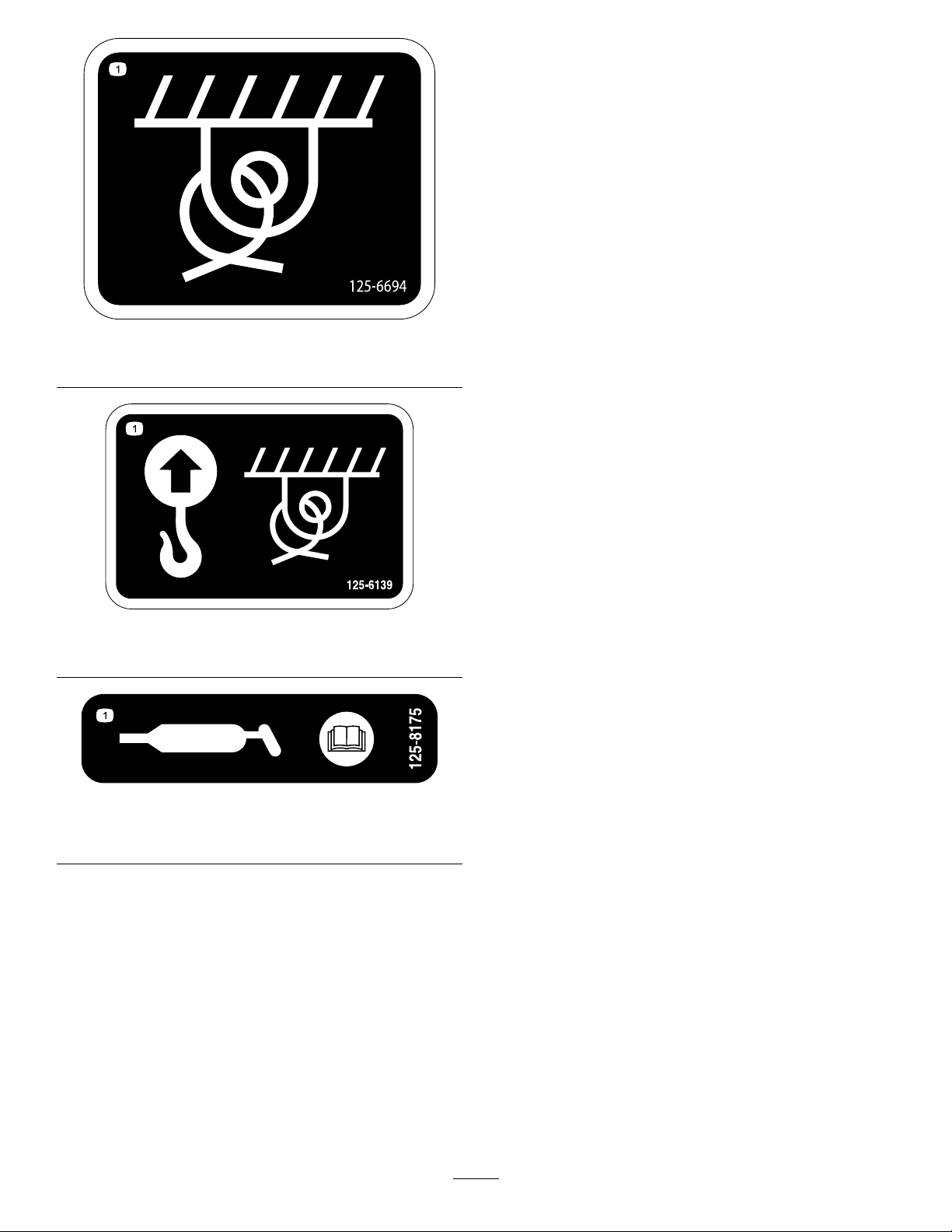
1.Tie-downpoint
1.Liftpointandtie-downpoint
125-6694
125-6139
125-8175
1.ReadtheOperator’sManualforinformationongreasing
themachine.
2
Page 3

Installation
LooseParts
Usethechartbelowtoverifythatallpartshavebeenshipped.
ProcedureDescription
1
2
3
4
5
Nopartsrequired
Bolt(3/4x31/2inch)
Bolt(3/4x4inch)
Washer23
Locknut12
Retainingring2
Clevispin
Upperspacerplate1
Uppermiddlespacerplate(withgrease
ttings)
Retainerplate2
Lowermiddlespacerplate(withgrease
ttings)
Lowerspacerplate1
Large90-degreetting
Small90-degreetting
46-inchhydraulichose2
Cableite
50-inchhydraulichose(F16tting)
50-inchhydraulichose(F12tting)
46-inchhydraulichose1
Reduceradapter1
Adapter1
Cabletie
Qty.
10
Use
–
2
1
1
1
1
1
1
1
1
1
Preparethemachine.
Installtheslidingoffsetattachment.
Installthehydrauliccylinderhoses.
Installthetrencherhydraulichoses.
Installthetrenchermotorhydraulic
hoses.
Model25445isrequiredforinstallingandusingthiskit.
1
PreparingtheMachine
NoPartsRequired
Procedure
1.Movethemachinetoalevelsurface.
Note:Ensurethatthefrontwheelsofthemachine
arestraight.
2.Settheparkingbrake,shutofftheengine,andremove
thekeyfromthekeyswitch.
3.Removethetrencherattachment;refertotheOperator’s
Manualforyourtrencher.
4.Rotatethebattery-disconnectswitchtotheOFF
position;refertotheOperator’ sManual.
Important:Ensurethattheliftingequipmenthasa
liftingcapacityofatleast405kg(893lb).
3
Page 4
2
InstallingtheSlidingOffset
Attachment
Partsneededforthisprocedure:
10
Bolt(3/4x31/2inch)
2
Bolt(3/4x4inch)
23Washer
12Locknut
2Retainingring
1
Clevispin
1Upperspacerplate
1
Uppermiddlespacerplate(withgreasettings)
2Retainerplate
1
Lowermiddlespacerplate(withgreasettings)
1Lowerspacerplate
Procedure
Important:Ensurethattheliftingequipmenthasa
liftingcapacityofatleast405kg(893lb).
1.Raisetheslidingoffsetattachmentofftheoorusing
liftingequipment.
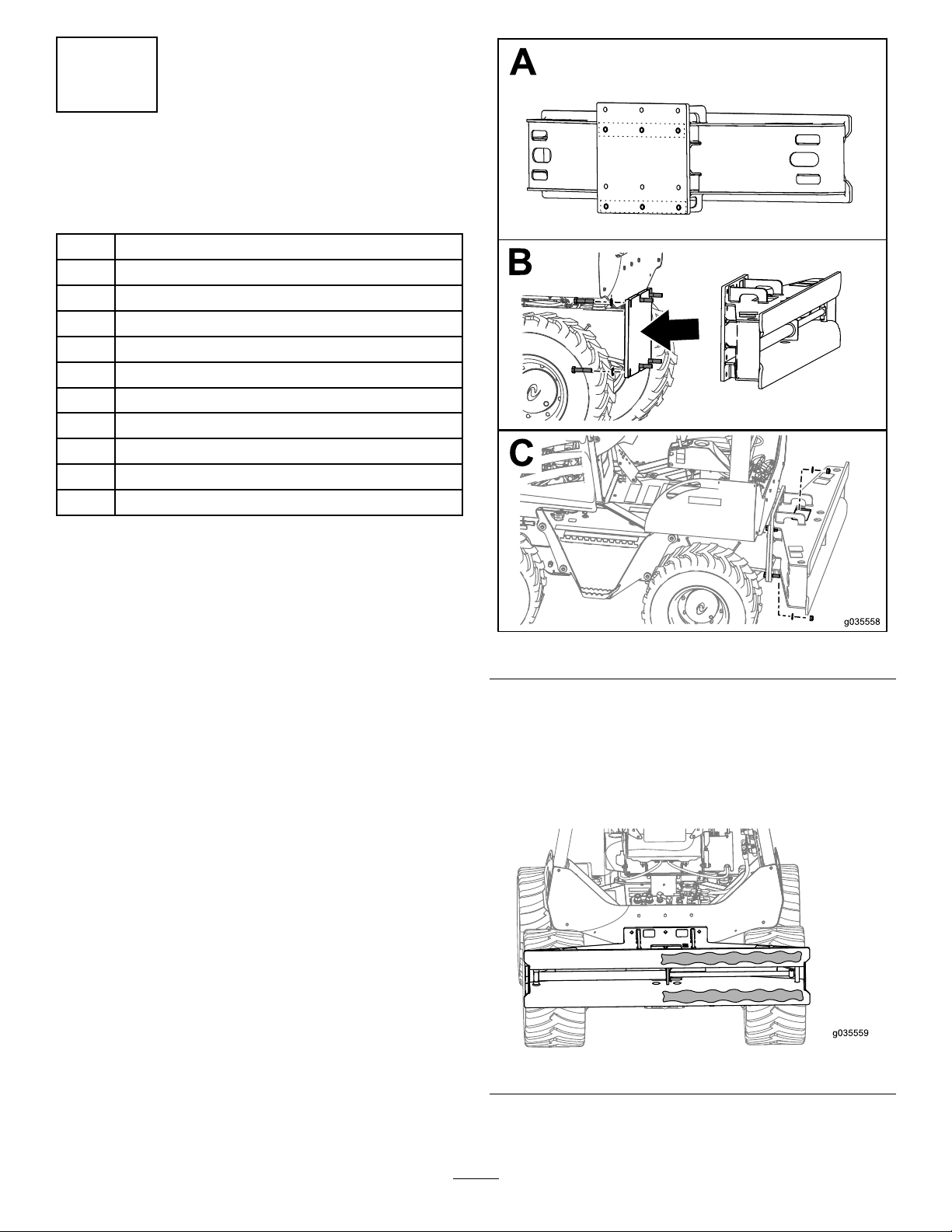
2.Locatethe2rowsofholesinthemountingplatethat
youwillusetosecuretheattachmenttothemachine
(BoxAofFigure1).
Figure1
3.Securetheslidingoffsetframeontothemachineusing
6bolts(3/4x31/2inch),12washers,and6locknuts
asshowninBoxBandBoxCofFigure1.
4.Torquetheboltsto456to560N∙m(337to413ft-lb).
5.Spreadsomegreaseontherightsideoftheattachment
frameasshowninFigure2.
Figure2
6.Securetheslidemountplatetothecylinderusingthe
clevispinand2retainingringsasshowninFigure3.
4
Page 5
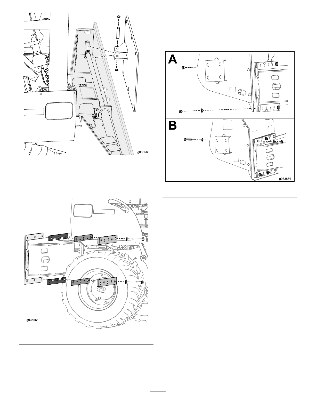
Figure3
9.Locatethe2rowsofholesinthemountingplatethat
youwillusetosecuretheattachmenttothesliding
offsetattachment.
10.Lowerthetrencherattachmentuntilitisalignedwith
theslidemountassembly .
7.Placetheupperandlowerspacerplatesontheslide
mountplateholdingtheminplacewiththe2bolts(3/4
x4inch)and2washersasshowninFigure4.
Figure5
11.SecurethetopboltwithalocknutasshowninBox
AofFigure5.
12.Securethebottomboltwithawasherandalocknutas
showninBoxAofFigure5.
13.Torquetheboltsto456to560N∙m(337to413ft-lb).
14.Place4bolts(3/4x31/2inch)and4washersthrough
thetrencherattachmentontotheslidemountand
securewith4washersand4locknuts(BoxBofFigure
2).
15.Torquetheboltsto456to560N∙m(337to413ft-lb).
Figure4
8.Raisethetrencherattachmentofftheoorusinglifting
equipment.
Important:Ensurethattheliftingequipmenthas
aliftingcapacityofatleast405kg(893lb).
5
Page 6
3
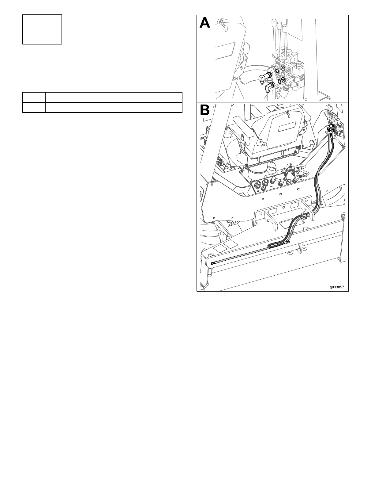
InstallingtheHydraulic CylinderHoses
Partsneededforthisprocedure:
1
Large90-degreetting
1
Small90-degreetting
Procedure
1.InstallthelargerttingandO-ringontothetopcenter
portonthehydraulicvalveasshowninBoxAof
Figure6.
Figure6
2.InstallthesmallerelbowttingandO-ringontothe
bottomcenterportonthehydraulicvalveasshownin
BoxAofFigure6.
3.Installthehosethatiscomingfromthecenterofthe
hydrauliccylindertothebottom90-degreettingas
showninBoxBofFigure6.
4.Installthehosethatiscomingfromtheendofthe
hydrauliccylindertothetop90-degreettingasshown
inBoxBofFigure6.
6
Page 7
4
InstallingtheTrencher
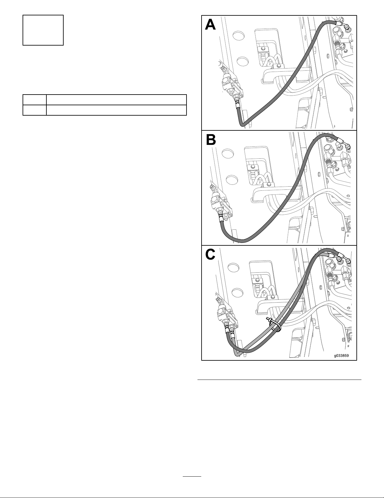
HydraulicHoses
Partsneededforthisprocedure:
246-inchhydraulichose
1
Cableite
Procedure
1.InstallthetrencherhydraulichosesasshowninFigure
7.
Figure7
2.Ensurethatthettingsonthehydraulicattachment
panelareinstalledasshowninFigure8.
•Thetopttingata60-degreeangle
•Thelowerttingata90-degreeangle
7
Page 8
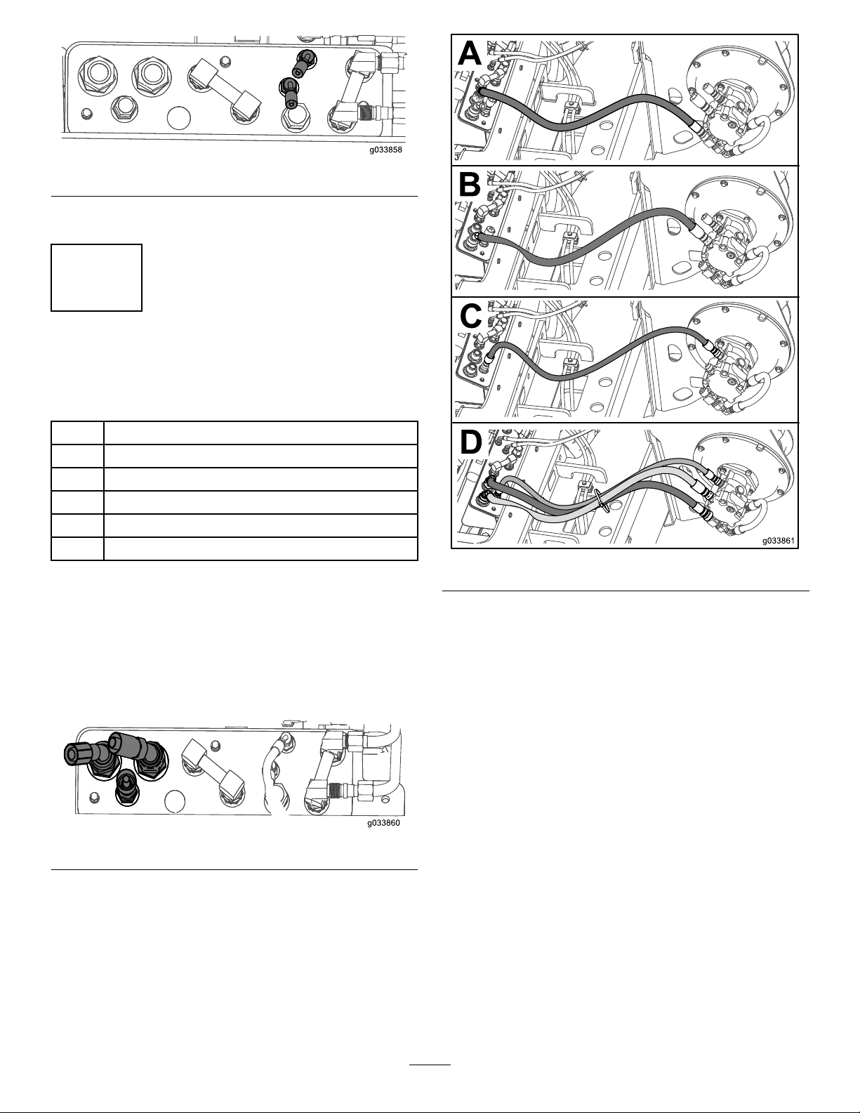
Figure8
3.Torquethettingsto20to28N∙m(15to21ft-lb).
5
InstallingTrencherMotor HydraulicHoses
Partsneededforthisprocedure:
1
50-inchhydraulichose(F16tting)
1
50-inchhydraulichose(F12tting)
146-inchhydraulichose
1Reduceradapter
1Adapter
1
Cabletie
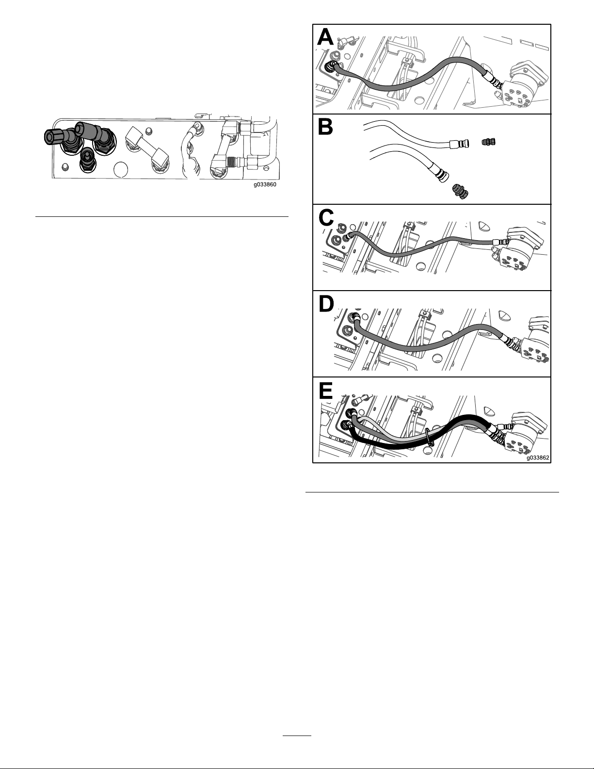
Figure10
InstallingtheHydraulicHosesforthe
Heavy-DutyTrencher
UseFigure9forthettingposition.
•F16ttingata108-degreeangle
•F12ttingata90-degreeangle
Figure9
1.Installthe50-inchhosewiththeF16ttingasshown
inBoxAofFigure10.
2.Torquethettingonthehydraulicattachmentpanelto
149to184N∙m(110to136ft-lb).
3.Torquethettingonthetrencherhydraulicmotorto
122to149N∙m(90to110ft-lb).
4.Installtheother50-inchhosewiththeF12ttingas
showninBoxBofFigure10.
5.Torquethettingonthehydraulicattachmentpanelto
149to184N∙m(110to136ft-lb).
6.Torquethettingonthetrencherhydraulicmotorto
89to111N∙m(66to82ft-lb).
7.Installthe46-inchhoseasshowninBoxCofFigure10.
8.Torquethettingonthehydraulicattachmentpanelto
58to72N∙m(43to53ft-lb).
9.Torquethettingonthetrencherhydraulicmotorto
58to72N∙m(43to53ft-lb).
10.Securethehoseswithacabletie(BoxDofFigure10).
8
Page 9
InstallingtheHydraulicHosesforthe
Direct-DriveTrencher
UseFigure11forthettingposition.
•F16ttingata108-degreeangle
•F12ttingata90-degreeangle
Figure11
1.Installthe50-inchhosewiththeF12ttingasshown
inBoxAofFigure12.
Figure12
2.Torquethettingonthehydraulicattachmentpanelto
149to184N∙m(110to136ft-lb).
3.Torquethettingonthetrencherhydraulicmotorto
89to111N∙m(66to82ft-lb).
4.Installthereduceradaptertothe50-inchhosewiththe
F16ttingasshowninBoxBofFigure12.
5.Torquethettingto89to110N∙m(66to82ft-lb).
6.Installtheotheradaptertothe46-inchhoseasshown
inBoxBofFigure12.
7.Torquethettingto45to56N∙m(33to41ft-lb).
8.Installtheother50-inchhosewiththeF16ttingas
showninBoxCofFigure12.
9.Torquethettingonthehydraulicattachmentpanelto
149to184N∙m(110to136ft-lb).
9
Page 10
10.Torquethettingonthetrencherhydraulicmotorto
122to149N∙m(90to110ft-lb).
Operation
11.Installthe46-inchhoseasshowninBoxDofFigure
12.
12.Torquethettingonthehydraulicattachmentpanelto
58to72N∙m(43to53ft-lb).
13.Torquethettingonthetrencherhydraulicmotorto
58to72N∙m(43to53ft-lb).
14.Securethehoseswithacabletie(BoxEofFigure12).
UsingtheSlidingOffsetKit
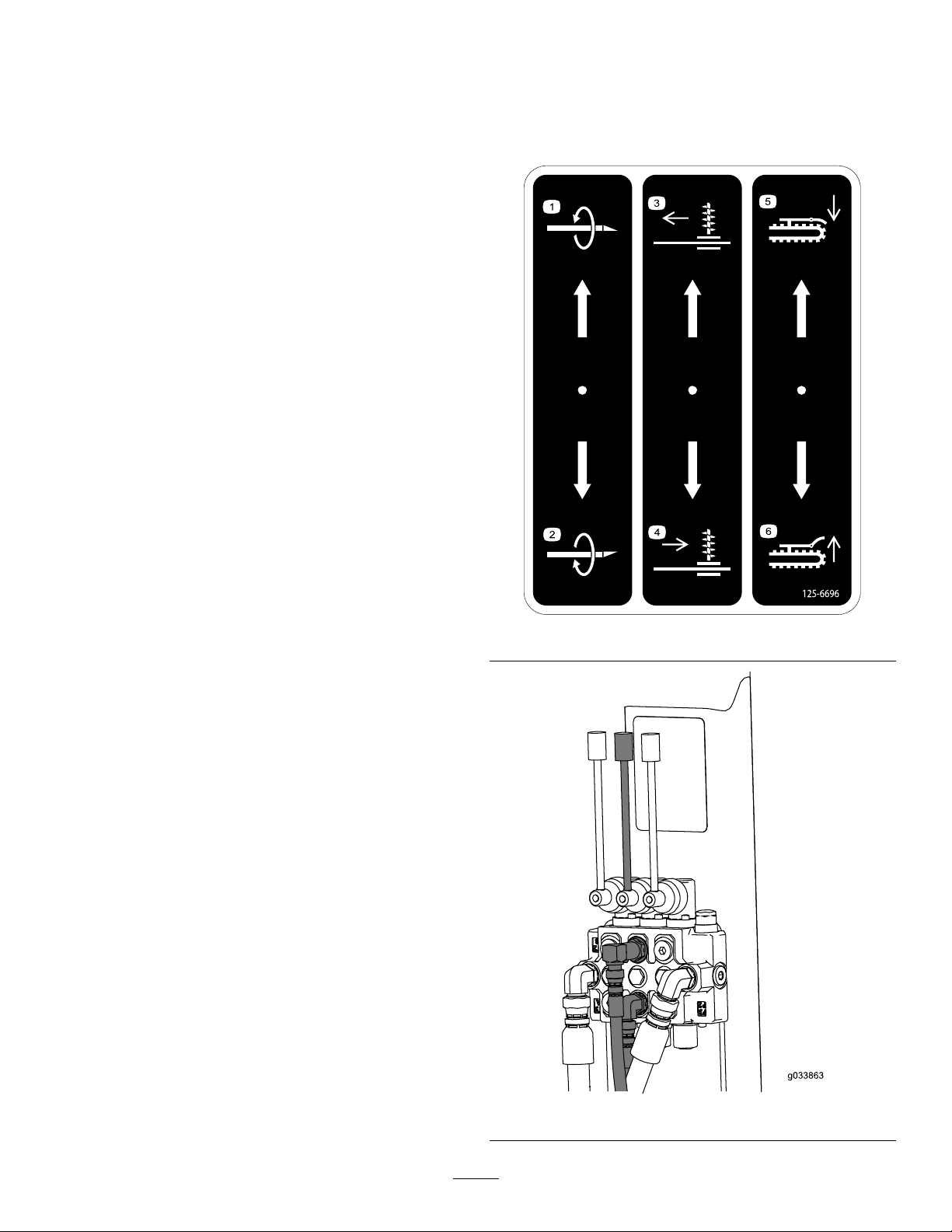
RefertothedecalinstalledwithkitModel25445andFigure
14.
Figure13
Figure14
10
Page 11
Maintenance
GreasingtheSliderFrame
ServiceInterval:Every50hours
GreaseType:Lithium-basedgrease.
Lowertheattachmenttothegroundtoensurethatthegrease
owsintothettingsproperly.
Cleanthegreasettingswitharag.
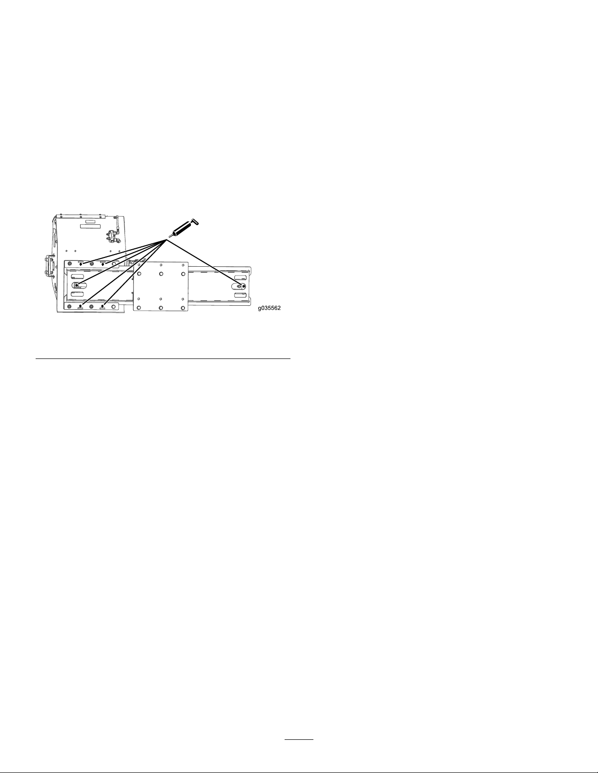
Connectthegreaseguntothegreasettingsfortheupper
andlowerpivots;apply2or3pumpsofgreasetoeachtting
(Figure15).
6greasettings
Figure15
11
Page 12

 Loading...