

Page 1
FormNo.3419-561RevA
Diesel-PoweredFM330Fluid
Mixer
ModelNo.23897—SerialNo.400000000andUp
Registeratwww.T oro.com.
OriginalInstructions(EN)
*3419-561*A
Page 2
ThisproductcomplieswithallrelevantEuropean
directives;fordetails,pleaseseetheseparate
product-specicDeclarationofConformity(DOC)
sheet.
WARNING
CALIFORNIA
Proposition65Warning
Thisproductcontainsachemical
orchemicalsknowntotheStateof
Californiatocausecancer,birthdefects,
orreproductiveharm.
Dieselengineexhaustandsomeofits
constituentsareknowntotheStateof
Californiatocausecancer,birthdefects,
andotherreproductiveharm.
Useofthisproductmaycauseexposure
tochemicalsknowntotheStateof
Californiatocausecancer,birthdefects,
orotherreproductiveharm.
accessoryinformation,helpndingadealer,orto
registeryourproduct.
Toensureoptimumperformanceandcontinuedsafety
certicationofthemachine,useonlygenuineT oro
replacementpartsandaccessories.Replacement
partsandaccessoriesmadebyothermanufacturers
couldbedangerous,andsuchusecouldvoidthe
productwarranty.
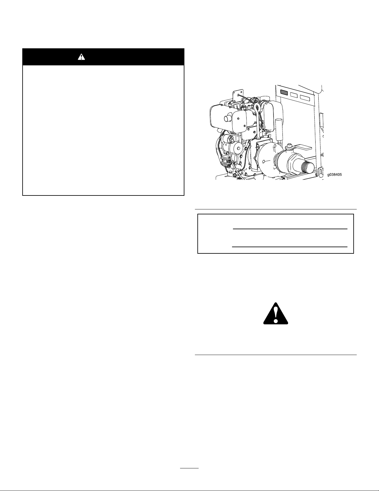
g038405
Figure1
ItisaviolationofCaliforniaPublicResourceCode
Section4442or4443touseoroperatetheengineon
anyforest-covered,brush-covered,orgrass-covered
landunlesstheengineisequippedwithaspark
arrester,asdenedinSection4442,maintainedin
effectiveworkingorderortheengineisconstructed,
equipped,andmaintainedforthepreventionofre.
TheenclosedEngineOwner'sManualis
suppliedforinformationregardingtheUS
EnvironmentalProtectionAgency(EPA)and
theCaliforniaEmissionControlRegulationof
emissionsystems,maintenance,andwarranty.
Replacementsmaybeorderedthroughtheengine
manufacturer.
Introduction
Thismachineisdesignedtomixdrilling-uidproducts
withcleanwater.Youcanmountthemachineontoa
suitabletransportvehicleandconnectthemachine
toasuitablehorizontaldirectionaldrill.Readand
understandthedirectionaldrillOperator’sManual.
1.Modelandserial-numberlocation
ModelNo.
SerialNo.
Thismanualidentiespotentialhazardsandhas
safetymessagesidentiedbythesafety-alertsymbol
(Figure2),whichsignalsahazardthatmaycause
seriousinjuryordeathifyoudonotfollowthe
recommendedprecautions.
g000502
Figure2
1.Safety-alertsymbol
Thismanualuses2wordstohighlightinformation.
Importantcallsattentiontospecialmechanical
informationandNoteemphasizesgeneralinformation
worthyofspecialattention.
Readthisinformationcarefullytolearnhowtooperate
andmaintainyourproductproperlyandtoavoid
injuryandproductdamage.Youareresponsiblefor
operatingtheproductproperlyandsafely .
YoumaycontactT orodirectlyatwww.Toro.com
productsafetyandoperationtrainingmaterials,
©2017—TheToro®Company
8111LyndaleAvenueSouth
Bloomington,MN55420
Contactusatwww.Toro.com.
2
PrintedintheUSA
AllRightsReserved
Page 3

Contents
Safety
Safety.......................................................................3
GeneralSafety...................................................3
SafetyandInstructionalDecals..........................4
Setup........................................................................6
ConnectingtheBattery.......................................6
ConnectingthePumptotheT ank.......................7
ProductOverview.....................................................8
Controls.............................................................8
Specications....................................................9
BeforeOperation...................................................9
BeforeOperationSafety.....................................9
GroundingtheMixerandtheTank.....................10
AdjustingtheValves.........................................10
AddingFuel......................................................10
DuringOperation..................................................11
DuringOperationSafety....................................11
StartingandShuttingOfftheEngine..................11
MixingtheFluid................................................13
PumpingtheFluidtotheDrill............................13
AfterOperation....................................................14
AfterOperationSafety......................................14
DrainingtheTank..............................................14
ProtectingtheMachinefromFreezing...............14
Maintenance...........................................................15
RecommendedMaintenanceSchedule(s)...........15
Pre-MaintenanceProcedures..............................15
Pre-MaintenanceSafety...................................15
PreparingtheMachineforMaintenance............15
Lubrication..........................................................16
LubricatingthePump........................................16
EngineMaintenance...........................................16
ServicingtheAirCleaner..................................16
ServicingtheEngineOil....................................17
FuelSystemMaintenance...................................19
ServicingtheFuelSystem................................19
ElectricalSystemMaintenance...........................20
ReplacingtheBattery.......................................20
ChargingtheBattery.........................................21
CheckingandCleaningtheBattery...................21
Cleaning..............................................................22
CleaningtheMachine.......................................22
Storage...................................................................22
StoringtheMachine..........................................22
Troubleshooting......................................................23
GeneralSafety
Thisproductiscapableofcausingpersonalinjury.
Alwaysfollowallsafetyinstructionstoavoidserious
personalinjury.
Usingthisproductforpurposesotherthanitsintended
usecouldprovedangeroustoyouandbystanders.
•Readandunderstandthecontentsofthis
Operator’sManualbeforestartingtheengine.
•Donotputyourhandsorfeetnearmoving
componentsofthemachine.
•Donotoperatethemachinewithoutallguards
andothersafetyprotectivedevicesinplaceand
workingonthemachine.
•Keepbystandersandpetsasafedistanceaway
fromthemachine.
•Neverallowchildrentooperatethemachine.
•Stopthemachineandshutofftheenginebefore
servicingorfuelingthemachine.
Improperlyusingormaintainingthismachinecan
resultininjury .T oreducethepotentialforinjury,
complywiththesesafetyinstructionsandalwayspay
attentiontothesafety-alertsymbol,whichmeans
Caution,Warning,orDanger—personalsafety
instruction.Failuretocomplywiththeseinstructions
mayresultinpersonalinjuryordeath.
Youcanndadditionalsafetyinformationwhere
neededthroughoutthisOperator’sManual.
3
Page 4
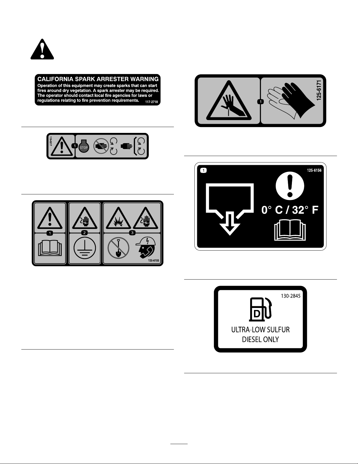
SafetyandInstructionalDecals
Safetydecalsandinstructionsareeasilyvisibletotheoperatorandarelocatednearanyarea
ofpotentialdanger.Replaceanydecalthatisdamagedormissing.
117-2718
119–0217
1.Warning—shutofftheengine;keepawayfrommoving
parts;keepallguardsandshieldsinplace.
decal117-2718
decal125-6171
125-6171
1.Piercinghazard—wearhandprotection.
decal119-0217
1.Warning—readthe
Operator’sManual.
2.Electricalshock
hazard—ensurethe
equipmentisgrounded
beforestartingdrill
operation.
decal125-6156
125–6156
decal125-6155
1.Tankdrain—readtheOperator’sManual.
125–6155
3.Explosionhazard;
electricalshock
hazard—Calllocal
utilitiesbeforedigging
underground.
decal130-2845
130–2845
4
Page 5
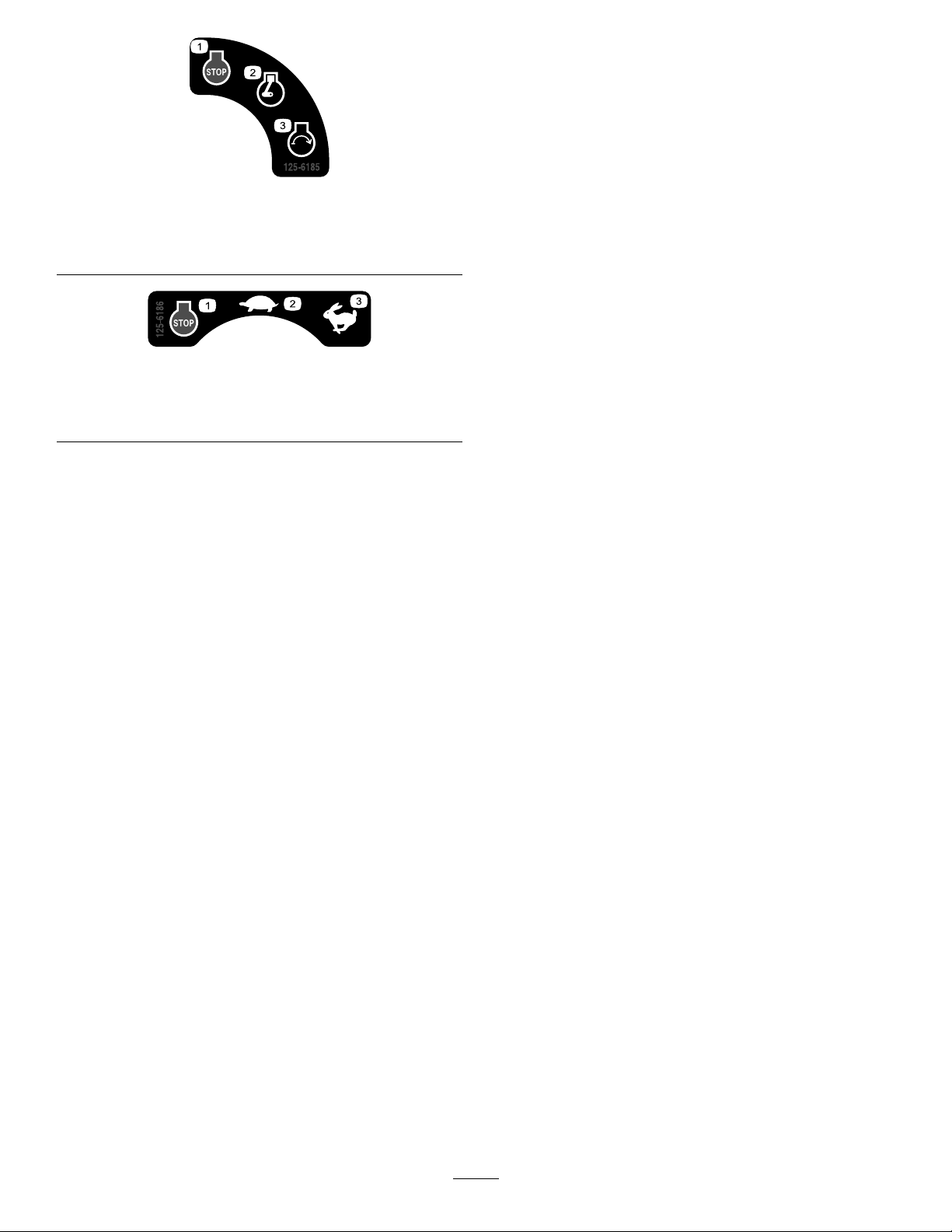
125-6185
1.Enginestop3.Enginestart
2.Enginerun
125-6186
1.Enginestop3.Fast
2.Slow
decal125-6185
decal125-6186
5
Page 6
Setup
LooseParts
Usethechartbelowtoverifythatallpartshavebeenshipped.
Description
Bolt(5/16x3/4inch)
Washer(5/16inch)
Nut(5/16inch)
Circulationhose
Hoseclamp2
MediaandAdditionalParts
Description
Transferhose
ConnectingtheBattery
WARNING
CALIFORNIA
Proposition65Warning
Batteryposts,terminals,andrelated
accessoriescontainleadandlead
compounds,chemicalsknownto
theStateofCaliforniatocause
cancerandreproductiveharm.Wash
handsafterhandling.
Qty.
Qty.
Use
2
2
2
1
1
Connectthebattery.
Connectthepumptothetank.
Use
Connectthemixertothedrill.
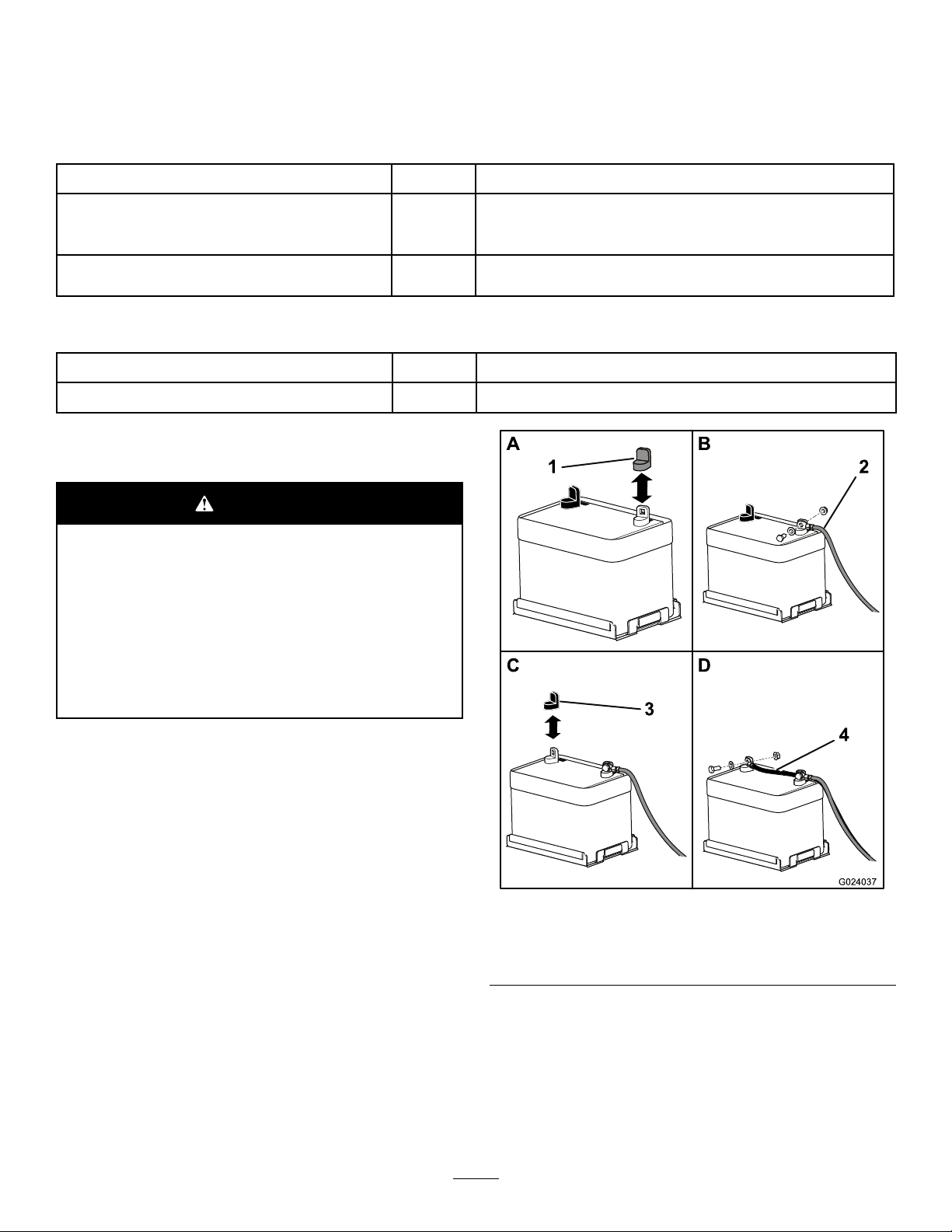
1.Removetheredplasticcoverfromthepositive
batteryterminal(Figure3).
g024037
Figure3
1.Redcover3.Blackcover
2.Positivecable4.Negativecable
2.Useabolt(5/16x3/4inch),awasher,andanut
(5/16inch)tomountthepositivecabletothe
positivebatteryterminal.
3.Removetheblackplasticcoverfromthe
negativebatteryterminal.
6
Page 7
4.Useabolt(5/16x3/4inch),awasher,andanut
(5/16inch)tomountthenegativecabletothe
negativebatteryterminal.
ConnectingthePumpto
theTank
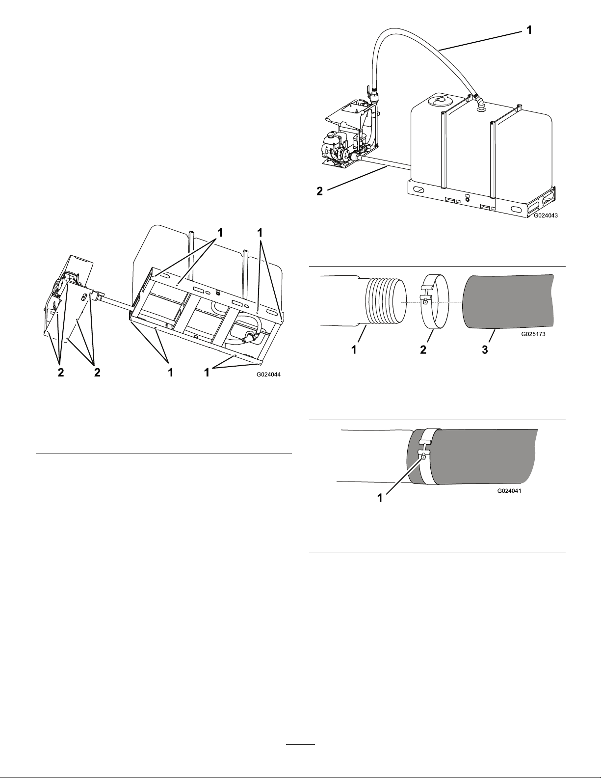
Ensurethattheframeoftheuidmixerandtheframe
ofthetankaresecuredtoastrongsurface,with
anadequatefastenerthrougheachmountinghole
(Figure4).
Note:Ensurethatthemixerandthetankareina
positionthatallowsthehosestoconnectthemwithout
stretchingorkinking.
g024043
Figure5
1.Circulationhose2.Suctionhose
Figure4
Undersideshown
1.Mountingholesintank
frame
2.Mountingholesinmixer
frame
1.Locatethesuctionhoseconnectedtothebottom
ofthetank,andpullthelooseendoutfrom
underthetank.
2.Useahoseclamp(providedwiththetransfer
hose)toconnectthelooseendofthesuction
hosetothepumpinletonthemixerasshownin
Figure5,Figure6,andFigure7.
g025173
Figure6
g024044
1.Fitting3.Hose
2.Hoseclamp
g024041
Figure7
1.Locknut
3.Tightenthehoseclampbytighteningthelocknut.
4.Use2hoseclamps(provided)toconnectthe
circulationhosetothetopofthetankandthe
topofthemixerasshowninFigure5,Figure6,
andFigure7.
5.Tightenthehoseclampsbytighteningthe
locknuts.
7
Page 8
ProductOverview
CirculationValve
Thecirculationvalve(Figure9)controlstheowfrom
thepumptothetank.
SuctionValve
Thesuctionvalve(Figure9)controlstheowfrom
thetanktothepump.
HopperValve
Thehoppervalve(Figure9)controlstheowfromthe
hopperintothemixingsystem.Thehoppervalveis
mosteffectivewhenitisjustslightlyopen,astheuid
thencreatesavacuumeffectanddrawsthebentonite
andothercomponentsintotheow.
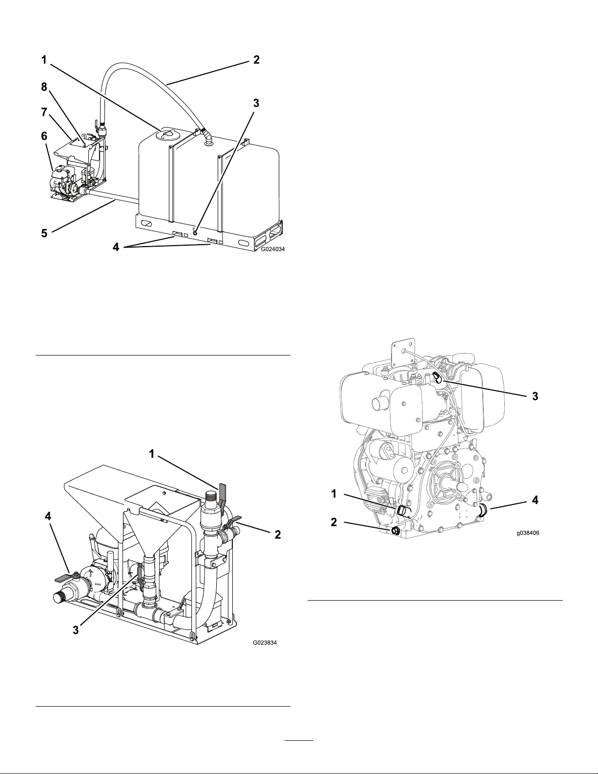
Figure8
Tanksoldseparately
1.Accesshatch
2.Circulation
hose
3.Tankdrainplug6.Engine
4.Forkliftpockets
5.Suctionhose8.Grate
7.Hopper
Controls
Becomefamiliarwithallthecontrolsbeforeyoustart
theengineandoperatethemachine.
g024034
TransferValve
Thetransfervalve(Figure9)controlstheowfrom
themixingsystemtothedrill.
EngineControls
Figure9
1.Circulationvalve
2.Transfervalve4.Suctionvalve
3.Hoppervalve
g038406
Figure10
1.Dipstick3.Decompressionlever
2.Oil-drainplug4.Oillter
g023834
8
Page 9

Figure11
1.Fuel-shutofflever
2.Fuel-injectionpump6.Aircleaner
3.Speed-controlhandle7.Recoil-Starthandle
4.Dipstick8.Fuel-drainplug
5.Ignitionswitch
IgnitionSwitch
Theignitionswitch(Figure11)allowstheoperatorof
themachinetostarttheengine;refertoStartingand
ShuttingOfftheEngine(page11).
Recoil-StartHandle
Ifthebatteryisnotcharged,youcanstarttheengine
withtherecoil-starthandle;refertoStartingand
ShuttingOfftheEngine(page11).
Speed-ControlHandle
Thespeed-controlhandle(Figure11)controlsthe
g038407
enginespeedandalsoshutsofftheengine.Movingit
allthewaytotheleft(counterclockwise)shutsoffthe
engine.Movingittotheright(clockwise)increases
theenginespeed.
Specications
Mixer
FlowrateLengthWidthHeightWeight
Upto1249L/minute
(330gallons/minute)
Tanks
Capacity
1893L(500USgallons)203.2cm(80inches)78.7cm(31inches)177.8cm(70inches)241kg(532lb)
3785L(1000US
gallons)
Operation
BeforeOperation
BeforeOperationSafety
GeneralSafety
•Theownermustensurethatalloperatorsare
welltrainedandcompetenttosafelyoperatethe
machine.
•Neverallowchildrenoruntrainedpeopleto
operateorservicethemachine.Localregulations
mayrestricttheageoftheoperator.
141cm(55inches)90cm(35inches)1 16.2cm(46inches)204kg(450lb)
LengthWidthHeightDryweight
257.2cm(101inches)108.6cm(43inches)191.1cm(75inches)397kg(876lb)
•Becomefamiliarwiththesafeoperationofthe
equipment,operatorcontrols,andsafetysigns.
•Knowhowtostopthemachineandshutoffthe
enginequickly.
•Checkthatsafetyswitchesandshieldsare
attachedandfunctioningproperly.Donotoperate
themachineunlesstheyarefunctioningproperly .
•Inspecttheareawhereyouwillusethemachine
andremoveallobjectsthatthemachinecould
throw.
•Keepthemanual(s)withthemachine.Goto
www.T oro.comforareplacementmanual.
9
Page 10

FuelSafety
•Useextremecareinhandlingfuel.Itisammable
anditsvaporsareexplosive.
•Extinguishallcigarettes,cigars,pipes,andother
sourcesofignition.
•Useonlyanapprovedfuelcontainer.
•Donotremovethefuelcaporllthefueltank
whiletheengineisrunningorhot.
•Donotaddordrainfuelinanenclosedspace.
•Donotstorethemachineorfuelcontainerwhere
thereisanopename,spark,orpilotlight,such
asonawaterheaterorotherappliance.
•Ifyouspillfuel,donotattempttostarttheengine;
avoidcreatinganysourceofignitionuntilthefuel
vaporshavedissipated.
Beforestartingtheengine,ensurethatthehopper
valveandthetransfervalvearebothclosed,andthe
suctionvalveandthecirculationvalvearebothopen
(Figure9).
AddingFuel
•Theenginerunsonclean,fresh,ultra-low-sulfur
dieselfuelwithaminimumcetaneratingof40.
•Purchasefuelinquantitiesthatcanbeusedwithin
30daystoensurefuelfreshness.
•Usesummer-gradedieselfuel(Number2-D)at
temperaturesabove-7°C(20°F)andwinter-grade
dieselfuel(Number1-DorNumber1-D/2-Dblend)
below-7°C(20°F).
•Nevermixkerosene,usedengineoil,orresidual
fuelswiththedieselfuel.
GroundingtheMixerand theTank
Groundthemixingsystem.
Connectabraidedgroundingstraporajumpercable
(soldseparately)fromthemixerframetotheground.
AdjustingtheValves
WARNING
Ifyouruntheenginewhenthemixingvalves
arenotadjustedasdirected,thepumpcan
directuidoutthroughthehopperandpush
thegrateintotheair.
Ensurethatthemixingvalvesareadjusted
appropriatelyandthatthegrateistetheredto
thehopper,beforestartingtheengine.
Toopenavalve,turnthehandlesothatitisinline
withthepipe.T ocloseavalve,turnthehandlesothat
itisperpendiculartothepipe(Figure12).
•Donotstorefueleitherinthefueltankorfuel
containersoverthewinter.
•Fueladditivesarenotrecommended.Somefuel
additivesmaycausepoorengineperformance.
Important:Donotmixoilwithdiesel.
Dieselfuelshouldcomplywiththefollowing
specication.Thetablelists7worldwide
specicationsfordieselfuels.
DieselFuelSpecications
Number2-D,Number1-D,ASTM
D975-94
EN590:96EuropeanUnion
ISO8217DMX
BS2869-A1orA2
JISK2204GradeNumber2
KSM-2610
GB252China
Location
USA
International
UnitedKingdom
Japan
Korea
UsingFuelStabilizer/Conditioner
Useadieselfuelstabilizer/conditionerinthemachine
tokeepthefuelfreshduringstorageof90daysor
less.Ifyouarestoringthemachineforlonger,drain
thefueltank;refertoDrainingtheTank(page14).
Figure12
1.Closedposition2.Openposition
Important:Donotusefueladditivescontaining
methanolorethanol.
Addthecorrectamountoffuelstabilizer/conditionerto
g024050
thefuel,andfollowthedirectionsofthemanufacturer.
Note:Fuelstabilizer/conditionerismosteffective
whenmixedwithfreshfuel.
10
Page 11

FillingtheFuelTank
Capacity:5.4L(5.7USqt)
DuringOperation
1.Parkthemachineonalevelsurface,shutoffthe
engine,andallowtheenginetocool.
2.Cleanaroundthefuel-tankcapandremoveit
(Figure13).
Figure13
1.Fuel-tankcap3.Redring
2.Inletfuelscreen
DuringOperationSafety
GeneralSafety
•Theowner/operatorcanpreventandisresponsible
foraccidentsthatmaycausepersonalinjuryor
propertydamage.
•Wearappropriateclothing,includinglongpants;
eyeandhearingprotection;slip-resistant,
substantialfootprotection;andhardhats.Tieback
longhairanddonotwearjewelry.
•Donotoperatethemachinewhileill,tired,or
undertheinuenceofalcoholordrugs.
•Operatethemachineonlyingoodvisibilitytoavoid
holesorhiddenhazards.
•Keepyourhandsandfeetawayfrommovingparts.
•Donotoperateneardrop-offs,ditches,or
embankments.
•Stopthemachinewheneveryouarenotoperating
g038408
it.
•Neverrunanengineinanareawhereexhaust
gassesareenclosed.
•Neverleavearunningmachineunattended.
Important:Keeptheinletfuelscreenand
theredringinthefueltankwhilepouringthe
fuel.
3.Addfueltothefueltankuntilthelevelisupto
theredring(Figure13andFigure14).
Important:Thisspaceinthetankallows
thefueltoexpand.Donotllthefueltank
completelyfull.
Figure14
•Beforeleavingtheoperatingposition,dothe
following:
–Movethemachinetolevelground.
–Shutofftheengineandremovethekey.
–Waitforallmovingpartstostop.
•Donotoperatethemachinewhenthereistherisk
oflightning.
•Useaccessories,attachments,andreplacement
partsapprovedbyTheT oro®Companyonly.
StartingandShuttingOff theEngine
WARNING
Ifyouruntheenginewhenthemixingvalves
g038409
arenotadjustedasdirected,thepumpcan
directuidoutthroughthehopperandpush
thegrateintotheair.
4.Installthefuel-tankcapsecurely.
5.Wipeupanyfuelthatmayhavespilled.
Ensurethatthemixingvalvesareadjusted
appropriatelyandthatthegrateistetheredto
thehopper,beforestartingtheengine.
11
Page 12

StartingtheEngine
Important:Becausetheuidcoolsthepump
seal,thepumpmayoverheatifyouruntheengine
withoutuidinthemixer.Donotruntheengine
withoutuidinthemixer.
StartingtheEngineusingtheKeySwitch
1.Movethefuel-shutofflevertotheONposition.
2.Movethespeed-controlhandletotheright
(Figure11);refertoControls(page8).
Note:Ifsmokecomesfromtheexhaust,move
thespeed-controlhandletotheleft.
3.RotatetheignitionswitchtotheRUNposition
(Figure11);refertoIgnitionSwitch(page9).
3.Pushthedecompressionlevertotheleft(Figure
10).
Note:Thedecompressionleverwillstay
cockedtotheleftandwillautomaticallyreturn
totheoriginalpositionwhentherecoilstarter
handleispulledagain.
4.Grasptherecoil-starthandle,pullitoutslowly
untilyoufeelresistance,thenpullitalltheway
outwithastrongandevenmotion(Figure16).
Note:Use2handsifnecessary.
g022414
Figure16
Figure15
1.Stopposition3.Startposition
2.Runposition
4.TurntheignitionswitchtotheST ARTposition,
andholditthereuntiltheenginestarts(Figure
15).
Important:Iftheenginedoesnotstart
within15seconds,releasethekey,andwait
atleast10secondsbeforeoperatingthe
starteragain.Usingtheelectricstarterfor
toolongwilloverheatthestartermotorand
candamageit.
Note:Ifafterseveralattemptsofstartingthe
exhaustbeginstoemitwhitesmoke,movethe
speedadjustmentleverallthewaytotheleft,
andpulltherecoil-starthandleoutslowly5
times.Repeatthestartingprocedure.
5.Slowlyreturntherecoil-starthandletotheinitial
position.
6.Iftheenginedoesnotstart,repeatsteps1to5.
g024065
ShuttingOfftheEngine
WARNING
Inanemergencysituation,shutofftheengine
immediately.
1.Movethespeed-controlhandletotheSTOP
position(Figure1 1);refertoIgnitionSwitch
(page9).
2.RotatetheignitionswitchtotheOFFposition;
refertoIgnitionSwitch(page9).
3.Movethefuel-shutofflevertotheOFFposition.
Important:KeeptheignitionswitchintheOFF
position.LeavingtheignitionswitchintheRUN
positionwhiletheengineisoffwilldischargethe
battery.
StartingtheEngineusingtheRecoilHandle
1.Movethefuel-shutofflevertotheONposition.
2.Movethespeed-controlhandletotheright
(Figure11);refertoControls(page8).
Note:Ifsmokecomesfromtheexhaust,move
thespeed-controlhandletotheleft.
12
Page 13

MixingtheFluid
thatallowsthedrycomponentstoenterthe
mixeratafasterrate.
WARNING
Ifyouruntheenginewhenthemixingvalves
arenotadjustedasdirected,thepumpcan
directuidoutthroughthehopperandpush
thegrateintotheair.
Ensurethatthemixingvalvesareadjusted
appropriatelyandthatthegrateistetheredto
thehopper,beforestartingtheengine.
WARNING
Drillinguidcanbeveryslippery.Ifthereare
drilling-uidcomponentsonthegroundor
othersurfaces,someonecouldslipandfall,
resultinginseriouspersonalinjury.
Wearslip-resistantfootwearandusecaution
whileworkinginareaswithdrilling-uid
components.
Thereisavarietyofmaterialsavailableforcreating
differenttypesofdrillinguid.Matchthedrillinguid
tosuittheneedsofthesoilconditions,andfollowthe
manufacturer’sinstructionsthatareprintedonthe
packagingoftheproduct.
Note:Theorderinwhichyouaddthecomponents
oftheuidisimportant.Followtheinstructionsofthe
manufacturers.
1.Ensurethatthegrateistetheredtothehopper
andthatthevalvesareadjustedappropriately;
refertoAdjustingtheValves(page10).
2.Addtheappropriateamountofwatertothetank
throughthehatch(Figure8).
Ifyouareusingwaterfromaditchorapond,
placeaverynescreenovertheinletofthe
hosetopreventunwantedmaterialfromentering
themixingsystem.
Ensurethatthereisenoughroomforadditives
inthemixingsystem.
3.Starttheengine;refertoStartingtheEngine
(page12).
6.Addtheappropriateamountofbentonitetothe
hopper.
Note:Addthebentoniteslowlytoavoid
clumping—1baginapproximately3to5
minutes.Openthetankcoverandlooktoensure
thattheuidcomponentsaremixingcorrectly .
Ifyouseeanyclumps,addthecomponentsat
aslowerrate.
7.Afteryouhaveaddedtheappropriateamountof
bentonite,addanypolymersthattheparticular
soilconditionsrequire.
8.Lastly,addanyotherliquidsthatthesoil
conditionsrequire.
9.Closethehoppervalve.
10.Allowthemachinetothoroughlymixtheuidfor
severalminutes.
PumpingtheFluidtothe Drill
DANGER
Theuidmixerwillbeelectriedifthehose
isattachedtothedrillandthedrillstrikes
anelectricalline.Contactingtheuidmixer
duringanelectricalstrikemaycausebodily
harm.
•Ensurethattheuid-mixerframeandthe
tankframearebondedtothegroundrod.
•Ifastrikeoccurs,stayawayfromtheuid
mixerandthedrill.Donotcontactthe
mixeruntiltheelectricalstrikehasbeen
corrected.
1.Usethetransferhose(provided)toconnectthe
mixerandthedrill.
Note:Themixerhasamalecamlocktting
(Figure17)locatedafterthetransfervalve.
4.TestthepHofthewater.Ifitisbelow8,add
sodaashuntilthepHis8orhigher.
Note:SuppliesfortestingpHareavailable
whereswimming-poolsuppliesaresold.
5.Slightlyopenthevalveatthebottomofthe
hopper.
Note:Thevalveworksmoreeffectivelywhenit
isopenonlyslightly;itcreatesavacuumeffect
13
Page 14

DrainingtheTank
Todrainthetank,removethedrainplugfromtheside
ofthetankframe(Figure8).
Disposeoftheuseddrillinguid,aswellastheunused
uidleftinthetank,accordingtoenvironmental
regulations.
ProtectingtheMachine fromFreezing
1.Ensurethatallthevalvesareopen.
2.Rinsethetankwithcleanclearwaterandthen
pumpitthroughthesystem,removingasmuch
oftheslurrymixinthesystemaspossible.
3.Drainthetank;refertoDrainingtheT ank(page
14).
4.Drainanyremaininguidfromthepumpby
removingthedrainpluginthebottomofthe
pump(Figure18).
Figure17
2.Openthetransfervalvetoallowtheuidtoow
tothedrill.
Note:Keepthecirculationvalveopensothat
theuidcontinuestocirculateinthemixer.
Important:Unlessyouareusingadditional
equipmenttothoroughlycleanthedrillinguid,
donotcirculatetheuseduidthroughthemixer.
Doingsomaydamagethepump.
Disposeoftheuseddrillinguid,aswellastheunused
uidleftinthetank,accordingtoenvironmental
regulations.
AfterOperation
AfterOperationSafety
g234696
g023837
Figure18
1.Drainplug
5.Topreventthevalveatthebaseofthehopper
fromfreezingaroundtheedges,eitherleave
thevalveopenhalfway,orclosethevalveand
pouranenvironmentallyfriendlyantifreezeinto
thehopperuntilabout51mm(2inches)ofuid
coversthevalve.
GeneralSafety
•Cleanupanyoilorfuelspills.
•Allowtheenginetocoolbeforestoringthemachine
inanyenclosure.
•Neverstorethemachineorfuelcontainerwhere
thereisanopename,spark,orpilotlight,such
asonawaterheateroronotherappliances.
14
Page 15

Maintenance
Important:Beforeperforminganymaintenanceprocedures,rstshutofftheengineandwait5minutes
toallowallmovingpartstocometoacompletestopandcool.
RecommendedMaintenanceSchedule(s)
MaintenanceService
Interval
Aftertherst25hours
Aftertherst50hours
Beforeeachuseordaily
Aftereachuse
Every50hours
Every100hours
Every200hours
Every400hours
MaintenanceProcedure
•Changetheengineoil.
•Inspectandcleantheengine-oillter.
•Inspecttheair-cleanerelement.
•Checktheengine-oillevel.
•Cleanthemachine.
•Cleantheair-cleanerelement.Cleanitmorefrequentlyindustyoperatingconditions.
•Cleantheinletfuelscreen.
•Lubricatethepump.
•Changetheengineoil.
•Checkthebatterycableconnections.
•Replacetheair-cleanerelement.Replaceitmorefrequentlyindustyoperating
conditions.
•Replacetheoutletfuellter.
•Inspectandcleantheengine-oillter.
Important:Refertoyourengineowner'smanualforadditionalmaintenanceprocedures.
Pre-Maintenance
Procedures
Pre-MaintenanceSafety
•Beforeadjusting,cleaning,repairing,orleaving
themachine,dothefollowing:
–Movethemachineonalevelsurface.
–Shutofftheengineandremovethekey.
–Waitforallmovingpartstostop.
–Allowmachinecomponentstocoolbefore
performingmaintenance.
•Ifpossible,donotperformmaintenancewhilethe
engineisrunning.Keepawayfrommovingparts.
•Useadequatesupporttosupportthemachineor
componentswhenrequired.
•Carefullyreleasepressurefromcomponentswith
storedenergy.
PreparingtheMachinefor Maintenance
1.Parkthetransportvehicleonalevelsurfaceand
chockthetires,orremovethemachinefromthe
transportvehicle.
2.Ensurethattheengineandmuferarecool.
3.Turntheelectric-startswitchtotheOFFposition.
15
Page 16

Lubrication
EngineMaintenance
LubricatingthePump
ServiceInterval:Every100hours
GreaseType:NLGI#1heavy-dutyEPgrease
Useagreaseguntopumpgreaseintothegrease
ttingonthesideofthepump(Figure19).
Figure19
ServicingtheAirCleaner
ServiceInterval:Beforeeachuseordaily—Inspect
theair-cleanerelement.
Every50hours—Cleantheair-cleanerelement.
Cleanitmorefrequentlyindustyoperating
conditions.
Every200hours/Y early(whichevercomes
rst)—Replacetheair-cleanerelement.
Replaceitmorefrequentlyindustyoperating
conditions.
Important:Donotoperatetheenginewithout
theairlterassembly;extremeenginedamage
willoccur.
1.Setthethrottletoslow,shutofftheengine,and
g023836
waitforallmovingpartstostop.
2.TurnthefuelshutofflevertotheOFFposition.
3.Removethewingnutthatsecurestheair-cleaner
cover(Figure20).
Figure20
1.Wingnut3.Paperelement
2.Air-cleanercover4.Foamelement
4.Removetheair-cleanercover.
5.Removetheinternalwingnut.
6.Removethefoamandpaperelementsfromthe
base(Figure20).
7.Removethefoamelementfromthepaper
element(Figure20).
8.Inspectthefoamandpaperelements,and
replacethemiftheyaredamagedorexcessively
dirty.
Note:Nevertrytobrushdirtoffthepaper
element;brushingforcesthedirtintothebers.
9.Wipedirtfromthebaseandthecoverwitha
moistrag.
g038411
16
Page 17

Note:Becarefultopreventdirtanddebris
fromenteringtheairductinsidetheair-cleaner
housing.
10.Slidetheouterfoamelementoverthepaper
element.
11.Installtheaircleanerelementsandensurethat
theyareproperlypositioned.
12.Installtheinternalwingnut
13.Securelyinstallthecoverwiththeotherwingnut.
ServicingtheEngineOil
ServiceInterval:Aftertherst25hours
Every100hours
CheckingtheEngine-OilLevel
ServiceInterval:Beforeeachuseordaily
Important:Use4-cycleengineoilthatmeets
orexceedsthefollowingguidelinesand
classications:
•APIServiceCategoriesCJ-4orhigher
•ACEAServiceCategoriesE-3,E-4,andE-5
Note:ToroPremiumEngineOilisavailablefromyour
AuthorizedT oroDealer.
CrankcaseCapacity:1.6L(1.7USqt)
Important:Iftheoillevelinthecrankcaseistoo
lowortoohighandyouruntheengine,youmay
damagetheengine.Thistypeofdamageisnot
coveredbythewarranty.
Viscosity:SAE5W-30
Note:Iftheambienttemperatureisabove35°C
(95°F),useSAE5W-40orSAE10W-40.
1.Placethemachineonaat,levelsurface.
2.Runtheengineforafewminutestowarmtheoil.
Note:Warmoilowsbetterandcarriesmore
contaminants.
3.Shutofftheengineandwaitforallmovingparts
tostop.
4.Cleanaroundthedipstick(Figure21)sothatdirt
cannotfallintothellerholeanddamagethe
engine.
g038410
Figure21
1.Dipstickupperlimit3.Fillport
2.Dipsticklowerlimit
5.Removethedipstickandwipetheendclean
(Figure21).
6.Slidethedipstickfullyintothellportwithout
threadingitintotheport.
7.Removethedipstickandlookattheend.
Note:Iftheengineoillevelisbelowthehalfway
pointonthehatchmarks,slowlypouronly
enoughoilintothellporttoraisethelevelto
thehalfwaypointonthedipstick.
8.Installthedipstick.
ChangingtheEngineOil
1.Ensurethatthemachineisonalevelsurface.
2.Runtheengineforafewminutestowarmtheoil.
Note:Warmoilowsbetterandcarriesmore
contaminants.
3.Shutofftheengineandwaitforallmovingparts
tostop.
4.Placeasuitablereceptacleundertheoildrain
plug(Figure22).
17
Page 18

Figure22
5.Removethedrainplug.
6.Allowtheoiltodrainandreplacethedrainplug.
7.Removethedipstick(Figure21)andslowlypour
oilintothellholeuntiltheoilisbetweenthe
upperandlowerlimitonthedipstick;referto
CheckingtheEngine-OilLevel(page17).
8.Installandsecurethedipstick.
9.Wipeupanyspilledoil.
8.Warmuptheenginebyrunningitfor5minutes,
andcheckforanyengineoilleaks.
9.Aftertheengineiswarm,turnitoffandletitsit
for10minutes.
10.Checktheengineoillevelbyfullyinserting,but
notscrewingin,thedipstick.
11.Addengineoilasneeded;refertoServicingthe
EngineOil(page17).
g038412
InspectingandCleaningthe Engine-OilFilter
ServiceInterval:Aftertherst50hours
Every400hours
1.Removetheoil-lterretainingbolt.
2.Pulltheoil-ltercapoutandremovetheoillter.
Figure23
3.Cleantheoillterorreplaceitifitisdamaged.
4.Installtheoillter.
5.Makesurethattheoil-ltercapisfullyseated.
6.Installandtightentheoil-lterretainingbolt.
7.Addnewengineoil;refertoServicingtheEngine
Oil(page17).
g038413
18
Page 19

FuelSystem
Maintenance
ServicingtheFuelSystem
DrainingtheFuelTankand ReplacingtheOutletFuelFilter
ServiceInterval:Every200hours—Replacethe
outletfuellter.
1.Shutofftheengineandwaitforallmovingparts
tostop.
CleaningtheInletFuelScreen
ServiceInterval:Every50hours—Cleantheinlet
fuelscreen.
1.Cleantheareaaroundthefuelcap.
2.Removethefuelcap.
3.Lifttheinletfuelscreenoutofthefueltank.
2.Placeanapprovedcontainerunderthefueltank
tocollectthefuel.
3.Removethefuelcap(Figure25).
g235178
Figure25
1.Fuelcap3.Drainplug
2.Gasket
4.Removethedrainplugandgaskettodrainthe
fuel(Figure25).
Figure24
1.Fuelcap3.Fueltank
2.Inletfuelscreen
4.Cleantheinletfuelscreenorreplaceitifitis
damaged.
5.Installtheinletfuelscreen.
6.Installthefuelcapandhandtightenit.
Note:Overtighteningthefuelcapwilldamage
it.
5.Loosenthenutsunderthefuel-shutofflever
(Figure26).
g019997
g021307
Figure26
1.Outletfuellter4.O-ring
2.Gasket5.Fuel-shutofflever
3.Fillerport
6.Nut(2)
19
Page 20

6.RemoveanddiscardtheO-ring(Figure26).
7.Pulltheoutletfuellterandgasketoutofthe
llerport(Figure26).
8.Installanewoutletfuellterandgasketthrough
thellerport,andseattheminthefueltank
(Figure26).
9.InstallanewO-ringonthefuelshutofflever,and
installtheassemblytothefueltankusingthe
nutsunderthefuelshutofflever(Figure26).
ElectricalSystem
Maintenance
ReplacingtheBattery
1.Removethecoverofthebatterybox.
2.Disconnectthenegative(black)groundcable
fromthebatterypost.
10.Installthedrainplugwithanewgasket(Figure
25).
11.Installthefuelcapandhandtightenit.
Note:Overtighteningthefuelcapwilldamage
it.
WARNING
Incorrectbatterycableroutingcould
damagethemachineandcables,causing
sparks.Sparkscancausethebattery
gasestoexplode,resultinginpersonal
injury.
•Alwaysdisconnectthenegative
(black)batterycablebefore
disconnectingthepositive(red)
cable.
•Alwaysconnectthepositive(red)
batterycablebeforeconnectingthe
negative(black)cable.
WARNING
Batteryterminalsormetaltools
couldshortagainstmetalmachine
components,causingsparks.Sparks
cancausethebatterygasestoexplode,
resultinginpersonalinjury .
•Whenremovingorinstallingthe
battery,donotallowthebattery
terminalstotouchanymetalpartsof
themachine.
•Donotallowmetaltoolstoshort
betweenthebatteryterminalsand
metalpartsofthemachine.
3.Removethepositive(red)batterycable.
4.Removethebattery.
5.Placethenewbatteryinthetray .
6.Installthepositive(red)batterycabletothe
positive(+)batteryterminal,andtightenthenut
ontothebolt.
7.Installthenegative(black)groundcabletothe
negative(-)batteryterminal,andtightenthenut
ontothebolt.
8.Installthecoverofthebatterybox,andsecureit
withthestrap.
9.Recycletheoldbatteryatanauthorizedfacility .
20
Page 21

ChargingtheBattery
WARNING
Chargingthebatteryproducesgasesthatcan
explode,seriouslyinjuringyouorbystanders.
Neversmokenearthebattery,andkeep
sparksandamesawayfromthebattery.
Important:Alwayskeepthebatteryfullycharged.
Thisisespeciallyimportanttopreventbattery
damagewhenthetemperatureisbelow0°C(32°F).
1.Chargethebatteryfor10to15minutesat25to
30A,or30minutesat10A.
CheckingandCleaningthe Battery
ServiceInterval:Every100hours—Checkthe
batterycableconnections.
Keepthetopofthebatteryclean.Ifthemachineis
storedinalocationwheretemperaturesareextremely
high,thebatterydischargesmorerapidlythanifthe
machineisstoredinacoolerlocation.
Keepthetopofthebatterycleanbywashingitwith
abrushdippedinammoniaorasolutionofsodium
bicarbonate.Flushthetopsurfacewithwaterafter
cleaning.Donotremovethellcapwhilecleaning
thebattery .
2.Whenthebatteryisfullycharged,unplugthe
chargerfromtheelectricaloutlet,anddisconnect
thechargerleadsfromthebatteryposts(Figure
27).
3.Installthebatteryinthemachineandconnect
thebatterycables;refertoConnectingthe
Battery(page6).
Important:Donotrunthemachinewiththe
batterydisconnected;electricaldamagemay
occur.
Thebatterycablesmustbetightontheterminalsto
providegoodelectricalcontact.
Ifcorrosionoccursatthebatteryterminals,disconnect
thecables,negative(-)cablerst,andscrapethe
clampsandterminalsseparately.Connectthecables,
positive(+)cablerst,andcoattheterminalswith
petroleumjelly.
Figure27
1.Positivebatterypost
2.Negativebatterypost
Ifthebatterynolongerholdsacharge,replaceit;refer
toCheckingandCleaningtheBattery(page21).
3.Red(+)chargerlead
4.Black(-)chargerlead
g000960
21
Page 22

Cleaning
Storage
CleaningtheMachine
Regularcleaningandwashingincreasesthelifespan
ofthemachine.Cleanthemachineaftereachuse,
beforethedirthardens.
Ensurethatthefuel-tankcapandoilcap/dipstickare
securetoavoidgettingwaterintheengine.
Usecarewhenusingahigh-pressuresprayer,
becauseitcandamagewarningdecals,instruction
signs,andtheengine.
StoringtheMachine
Forstorageover30days,preparethemachineas
follows:
1.Removedirtandgrimefromtheexternalpartsof
theentiremachine,especiallytheengine.Clean
dirtanddebrisfromtheoutsideoftheengine
cylinder-headnsandblowerhousing.
Important:Youcanwashthemachinewith
milddetergentandwater.
2.Conditionthefuelsystemasfollows:
A.Addapetroleum-based
stabilizer/conditionertofuelinthe
tank.Followthemixinginstructionsfrom
thestabilizermanufacturer.Donotuse
analcohol-basedstabilizer(ethanolor
methanol).
Important:Donotstore
stabilizer/conditionedfuelover90
days.
Note:Fuelstabilizer/conditionerismost
effectivewhenmixedwithfreshfueland
usedatalltimes.
B.Runtheenginefor5minutestodistribute
theconditionedfuelthroughthefuelsystem.
Important:Runningtheenginewithout
waterinthetankwilldamagethepump.
C.Shutofftheengine,allowittocool,and
drainthefueltankusingapump-type
siphon.Disposeoffuelproperly;recycleit
accordingtolocalcodes.
D.Starttheengineandrunituntilitshutsoff.
E.Choketheengine.
F.Startandruntheengineuntilitdoesnot
startagain.
3.Servicetheaircleaner;refertoServicingtheAir
Cleaner(page16).
4.Changetheenginecrankcaseoil;referto
ChangingtheEngineOil(page17).
5.Greasethemachine;refertoLubricatingthe
Pump(page16).
6.Checkandtightenallbolts,nuts,andscrews.
Repairorreplaceanypartthatisdamaged.
7.Paintallscratchedorbaremetalsurfaces.Paint
isavailablefromyourAuthorizedT oroDealer.
8.Storethemachineinaclean,drygarageor
storagearea.
9.Coverthemachinetoprotectitandkeepitclean.
22
Page 23

Troubleshooting
Problem
Theenginedoesnotstart.
Theenginelackspowerorrunsrough.
Theuiddoesnotcirculateatfull
efciency.
PossibleCauseCorrectiveAction
1.TheengineOn/OffswitchisintheOFF
position.
2.Thefueltankisempty.2.Fillthefueltankwithfreshfuel.
3.Theenginecontainsbadoroldfuel.3.Drainthefueltank.Fillthefueltank
1.Theairlterisrestricted.1.Cleanorreplacetheair-lter
2.Theenginecontainsbadoroldfuel.2.Drainthefueltank.Fillthefueltank
3.Thereiswaterorcontaminationinthe
fuel.
4.Thefuellineisrestricted.4.Cleanthefuellter.
5.Thereistoomuchoilintheengine
crankcase.
1.Thepumpinletisclogged.
1.RotatetheswitchtotheONposition.
withfreshfuel.
element(s).
withfreshfuel.
3.Drainthefueltank.Fillthefueltank
withfreshfuel.
5.Draintheoiltotheproperlevel.
1.ContactanAuthorizedServiceDealer.
23
Page 24

EuropeanPrivacyNotice
TheInformationT oroCollects
ToroWarrantyCompany(T oro)respectsyourprivacy.Inordertoprocessyourwarrantyclaimandcontactyouintheeventofaproductrecall,weaskyou
tosharecertainpersonalinformationwithus,eitherdirectlyorthroughyourlocalT orocompanyordealer.
TheT orowarrantysystemishostedonserverslocatedwithintheUnitedStateswhereprivacylawmaynotprovidethesameprotectionasapplies
inyourcountry.
BYSHARINGYOURPERSONALINFORMATIONWITHUS,YOUARECONSENTINGTOTHEPROCESSINGOFYOURPERSONALINFORMATION
ASDESCRIBEDINTHISPRIV ACYNOTICE.
TheW ayT oroUsesInformation
Toromayuseyourpersonalinformationtoprocesswarrantyclaims,tocontactyouintheeventofaproductrecallandforanyotherpurposewhichwetell
youabout.ToromayshareyourinformationwithT oro'safliates,dealersorotherbusinesspartnersinconnectionwithanyoftheseactivities.Wewillnot
sellyourpersonalinformationtoanyothercompany.Wereservetherighttodisclosepersonalinformationinordertocomplywithapplicablelawsand
withrequestsbytheappropriateauthorities,tooperateoursystemsproperlyorforourownprotectionorthatofotherusers.
RetentionofyourPersonalInformation
Wewillkeepyourpersonalinformationaslongasweneeditforthepurposesforwhichitwasoriginallycollectedorforotherlegitimatepurposes
(suchasregulatorycompliance),orasrequiredbyapplicablelaw .
Toro'sCommitmenttoSecurityofYourPersonalInformation
Wetakereasonableprecautionsinordertoprotectthesecurityofyourpersonalinformation.Wealsotakestepstomaintaintheaccuracyandcurrent
statusofpersonalinformation.
AccessandCorrectionofyourPersonalInformation
Ifyouwouldliketorevieworcorrectyourpersonalinformation,pleasecontactusbyemailatlegal@toro.com.
AustralianConsumerLaw
AustraliancustomerswillnddetailsrelatingtotheAustralianConsumerLaweitherinsidetheboxoratyourlocalToroDealer.
374-0282RevC
 Loading...