

Page 1

FormNo.3383-981RevA
G024228
Diesel-PoweredFM330Fluid
Mixer
ModelNo.23892—SerialNo.313000001andUp
Registeratwww.T oro.com.
OriginalInstructions(EN)
*3383-981*A
Page 2

ThisproductcomplieswithallrelevantEuropeandirectives.
1
G023835
Fordetails,pleaseseetheseparateproduct-specic
DeclarationofConformity(DOC)sheet.
WARNING
CALIFORNIA
Proposition65Warning
Thisproductcontainsachemicalorchemicals
knowntotheStateofCaliforniatocausecancer,
birthdefects,orreproductiveharm.
Dieselengineexhaustandsomeofits
constituentsareknowntotheStateof
Californiatocausecancer,birthdefects,
andotherreproductiveharm.
Useofthisproductmaycauseexposureto
chemicalsknowntotheStateofCalifornia
tocausecancer,birthdefects,orother
reproductiveharm.
Readthisinformationcarefullytolearnhowtooperateand
maintainyourproductproperlyandtoavoidinjuryand
productdamage.Youareresponsibleforoperatingthe
productproperlyandsafely.
YoumaycontactTorodirectlyatwww .Toro.comforproduct
andaccessoryinformation,helpndingadealer,ortoregister
yourproduct.
Wheneveryouneedservice,genuineT oroparts,oradditional
information,contactanAuthorizedServiceDealerorToro
CustomerServiceandhavethemodelandserialnumbersof
yourproductready .Writethenumbersinthespaceprovided.
Becauseinsomeareastherearelocal,state,orfederal
regulationsrequiringthatasparkarresterbeusedonthe
engineofthismachine,asparkarresterisavailableas
anoption.Ifyourequireasparkarrester,contactyour
AuthorizedToroServiceDealer.
GenuineT orosparkarrestersareapprovedbytheUSDA
ForestryService.
Important:ItisaviolationofCaliforniaPublic
ResourceCodeSection4442touseoroperatetheengine
onanyforest-covered,brush-covered,orgrass-covered
landwithoutasparkarrestermufermaintainedin
workingorder,ortheengineconstricted,equipped,and
maintainedforthepreventionofre.Otherstatesor
federalareasmayhavesimilarlaws.
Theenclosed
Engine Owner's Man ual
issuppliedfor
informationregardingtheUSEnvironmentalProtection
Agency(EPA)andtheCaliforniaEmissionControl
Regulationofemissionsystems,maintenance,and
warranty.Replacementsmaybeorderedthroughthe
enginemanufacturer.
Figure1
1.Modelandserialnumberlocation
ModelNo.
SerialNo.
Thismanualidentiespotentialhazardsandhassafety
messagesidentiedbythesafetyalertsymbol(Figure2),
whichsignalsahazardthatmaycauseseriousinjuryordeath
ifyoudonotfollowtherecommendedprecautions.
Introduction
Thismachineisdesignedtomixdrilling-uidproducts
withcleanwater.Youcanmountthemachineontoa
suitabletransportvehicleandconnectthemachinetoa
suitablehorizontaldirectionaldrill.Readandunderstandthe
directionaldrillOperator’sManual.
©2014—TheToro®Company
8111LyndaleAvenueSouth
Bloomington,MN55420
Figure2
1.Safetyalertsymbol
Thismanualuses2wordstohighlightinformation.
Importantcallsattentiontospecialmechanicalinformation
Contactusatwww.Toro.com.
2
PrintedintheUSA
AllRightsReserved
Page 3

andNoteemphasizesgeneralinformationworthyofspecial
attention.
Contents
Introduction..................................................................2
Safety...........................................................................3
SafeOperatingPractices...........................................3
SoundPowerLevel..................................................5
SoundPressureLevel...............................................5
SafetyandInstructionalDecals.................................6
Setup............................................................................8
ConnectingtheBattery.............................................8
ConnectingthePumptotheTank..............................9
ProductOverview.........................................................10
Controls...............................................................10
Specications........................................................12
Operation....................................................................12
PreparingtoUsetheMachine...................................12
GroundingtheMixerandtheTank...........................12
AdjustingtheValves...............................................12
AddingFuel...........................................................12
CheckingtheEngine-oilLevel..................................14
StartingandStoppingtheEngine..............................14
MixingtheFluid.....................................................15
PumpingtheFluidtotheDrill..................................16
DrainingtheTank..................................................16
ProtectingtheMachinefromFreezing.......................17
OperatingTips......................................................17
Maintenance.................................................................18
RecommendedMaintenanceSchedule(s)......................18
PremaintenanceProcedures........................................18
PreparingtheMachineforMaintenance.....................18
Lubrication...............................................................18
LubricatingthePump.............................................18
EngineMaintenance..................................................19
ServicingtheAirCleaner.........................................19
ServicingtheEngineOil..........................................19
FuelSystemMaintenance...........................................20
CheckingtheWaterTrap.........................................20
ReplacingtheFuelFilter..........................................21
ElectricalSystemMaintenance....................................21
ReplacingtheBattery..............................................21
ChargingtheBattery...............................................22
CheckingandCleaningtheBattery............................22
Cleaning...................................................................23
CleaningtheMachine..............................................23
Storage........................................................................23
StoringtheMachine................................................23
Troubleshooting...........................................................24
Safety
Improperlyusingormaintainingthemachinecanresult
ininjury.T oreducethepotentialforinjury,complywith
thesesafetyinstructionsandalwayspayattentiontothe
safetyalertsymbol,whichmeans:
or
Danger
complywiththeinstructionmayresultinpersonalinjury
ordeath.
—personalsafetyinstruction.Failureto
SafeOperatingPractices
Alwaysfollowallsafetyinstructionstoavoidseriousinjury
ordeath.
WARNING
Handlingvariousdrilling-uidmaterialscan
generatedustandfumescontainingchemicals,
suchassilica,knowntocauseseriousorfatalinjury
orillness,suchasrespiratorydisease,silicosis,
cancer,birthdefects,orotherreproductiveharm.
•Usegoodworkpracticesandfollowthe
recommendationsofthemanufactureror
suppliers,OSHA,andotheroccupationaland
tradeassociations.
•Alwaysfollowrespiratoryprecautions.
•Whenthehazardsfrominhalationcannotbe
eliminated,theoperatorandanybystanders
shouldweararespiratorapprovedbyOSHAfor
thematerialbeinghandled.
WARNING
Engineexhaustcontainscarbonmonoxide,an
odorless,deadlypoisonthatcankillyou.
Donotruntheengineindoorsorinanenclosed
area.
Training
•ReadtheOperator'sManualandothertrainingmaterial.If
theoperator(s)ormechanic(s)cannotreadorunderstand
theinformation,itistheowner'sresponsibilitytoexplain
thismaterialtothem.
•Becomefamiliarwiththesafeoperationoftheequipment,
operatorcontrols,andsafetysigns.
•Alloperatorsandmechanicsshouldbetrained.The
ownerisresponsiblefortrainingtheusers.
•Neverletchildrenoruntrainedpeopleoperateorservice
theequipment.Localregulationsmayrestricttheageof
theoperator.
•Theowner/usercanpreventandisresponsiblefor
accidentsorinjuriestopeopleordamagetoproperty.
Caution
,
W ar ning
,
3
Page 4

Preparation
Becomefamiliarwiththesafeoperationoftheequipment,
operatorcontrols,andsafetysigns.
•Useonlyaccessoriesandattachmentsapprovedbythe
manufacturer.
•Weararespiratororadustmask.
•Operatingtheequipmentsafelyrequiresthefullattention
oftheoperator.Donotwearradioormusicheadphones
whileoperatingthemachine.
•Useextracarewhenhandlingfuels.Theyareammable,
andthevaporsareexplosive.Usethefollowingpractices
whenhandlingfuel:
–Useonlyanapprovedfuelcontainer.
–Neverremovethefuelcaporaddfuelwiththeengine
running.
–Allowtheenginetocoolbeforerefueling.
–Donotsmoke.
–Neveraddfuelordrainthemachineindoors.
–Replacethefuelcapandtightenitsecurely .
–Keepthecontainernozzleincontactwiththetank
duringlling.
–Neverllacontainerwhileitisinsideavehicle,trunk,
pick-upbed,oranysurfaceotherthantheground.
–Neverstorethemachineorfuelcontainerinside
wherethereisanopename,suchasnearawater
heaterorfurnace.
–Iffuelisspilled,wipeitofftheengineandequipment.
•Ensurethatthemachineisonalevelsurfacebefore
operatingthemachine.
•Beforeeveryuse,ensurethatthemachineisproperly
secured.
Operation
•Neverrunanengineinanenclosedorpoorlyventilated
area.
•Onlyoperatethemachineingoodlightingconditions.
•Beforestartingthemachine,makesurethatthereareno
personsorobstaclesnearorunderthemachine.
•Stoptheenginebeforeleavingthemachineforany
reason.
Neverleavearunningmachineunattended.Alwaysstop
theengineandverifythatallmovingpartshavestopped.
•Avoidprolongedbreathingofexhaustfumes.Engine
exhaustfumescancausesicknessordeath.
•Donotoperatethemachineundertheinuenceof
alcoholordrugs.
•Ensurethattheareaisclearofotherpeopleorpetsbefore
operatingthemachine.Stopthemachineifanyoneenters
thearea.
•Donottouchpartswhichmaybehotfromoperation.
Allowthemtocoolbeforeattemptingtomaintain,adjust,
orservicethemachine.
•Nevermovethemachinewhiletheengineisrunning.
•Ensurethatalltheguardsandshieldsaresecurelyinplace
beforeoperatingthemachine.
•Ifthemachineshouldstartmakinganunusualnoiseor
vibration,stoptheengine.Waitforallmovingpartsto
cometoacompletestopandcool.Vibrationisgenerally
awarningoftrouble.Inspectforcloggingordamage.
Cleanandrepairand/orreplacedamagedparts.
•Donotchangetheenginegovernorsettingoroverspeed
theengine.
•Lightningcancausesevereinjuryordeath.Ifyousee
lightningorhearthunderinthearea,donotoperatethe
machine;seekshelter.
MaintenanceandStorage
•Beforeperformingmaintenance,dothefollowing:
–Ensurethatthemachineisonlevelground.
–Stoptheengine.Waitforallmovementtostopbefore
adjusting,cleaning,orrepairing.
–Lettheenginecoolbeforeperformingmaintenance
orstoring.
–Disengageallpowerandoperationcontrols.
•Neverlubricate,service,repair,oradjustthemachine
whileitisrunning.
•Keepequipmentmaterialsclearfromthemuferand
enginetohelppreventres.Cleanupanyoilorfuel
spillage.
•Neverallowuntrainedpersonneltoservicethemachine.
•Keephands,feet,andclothingawayfrommovingparts.
Ifpossible,donotmakeadjustmentswiththeengine
running.
•Keepallpartsingoodworkingconditionandallhardware
tightened.Replaceallwornordamageddecals.
•Removeanybuildupofgrease,oil,ordebrisfromthe
machine.
•Stopandinspectthemachineifaforeignobjectenters
thehopperorcausesanotherobstruction.Makeany
necessaryrepairsbeforestartingthemachine.
•Donottamperwithsafetydevices.
•Keepallnuts,bolts,screws,andhoseclampssecurely
tightened.Keepequipmentingoodcondition.
•Tobestprotectyourinvestmentandmaintainoptimal
performanceofyourToroequipment,countonToro
genuineparts.Whenitcomestoreliability ,Torodelivers
replacementpartsdesignedtotheexactengineering
specicationsofourequipment.Forpeaceofmind,insist
onTorogenuineparts.
4
Page 5

Hauling
1
G024270
4
2
3
•Ensurethatthetransportvehiclehasacarryingcapacity
tohandletheweightofthemachineandafulltankof
uid—inadditiontoanyothermachinesormaterials
thatthetransportvehiclemayneedtocarry.Themixing
systemalonerequiresacarryingcapacityofatleast2,268
kg(5,000lb)forasystemthatusesasingle1,893L
(500-gallon)tank,upto9,072kg(20,000lb)forasystem
thatusestwo3,785L(1000-gallon)tanks.
•Usecarewhenloadingorunloadingthemachineontoa
trailerortruck.
•Ensurethatthetankisemptybeforeloadingthemachine
ontoatrailerortruck.
•Securethemachineusingadequateboltsthroughallthe
mountingholesofboththemixerframeandthetank
frame.
SoundPowerLevel
Thisunithasasoundpowerlevelof108dBA,whichincludes
anUncertaintyValue(K)of1dBA.
Thesoundpowerlevelwasdeterminedaccordingtothe
proceduresoutlinedinEN/ISO3744.
SoundPressureLevel
Thisunithasasoundpressurelevelattheoperator’ searof95
dBA,whichincludesanUncertaintyValue(K)of1dBA.
Asthisproductdoesnothaveadedicatedoperator’sposition,
thesoundpressurelevelwasdeterminedaccordingtothe
proceduresoutlinedintheMachinerySafetyDirective
2006/42/EC.
Measurementsweretakenonall4sidesofthemachinewith
themicrophonepositionedalongthecenterlineofthearea
facingthemicrophone.Ineachcase,themicrophonewas
locatedataheightof1.6mfromthegroundandadistanceof
1.0mfromthesurfaceareaofthemachine.Forthismodel,
theloudesttestedpointisshowninFigure3.
Figure3
1.1.0m(39inches)3.1.6m(63inches)
2.Measurementpoint
4.Centerlineofthemachine
5
Page 6

SafetyandInstructionalDecals
Safetydecalsandinstructionsareeasilyvisibletotheoperatorandarelocatednearanyareaofpotential
danger.Replaceanydecalthatisdamagedorlost.
117-2718
125–6155
119–0217
1.Warning—stoptheengine;keepawayfrommovingparts;
keepallguardsandshieldsinplace.
125–6136
1.Warning—readthe
Operator’sManual.
2.Electricalshock
hazard—ensurethe
equipmentisgrounded
beforestartingdrill
operation.
3.Explosionhazard;
electricalshock
hazard—Calllocal
utilitiesbeforedigging
underground.
125–6156
1.Tankdrain—readtheOperator’sManual.
125-6171
1.Piercinghazard—wearhandprotection.
6
Page 7

125-6177
1.Fast3.Warning—donotstopthe
2.Slow
engineathighspeeds;
onlystoptheengineat
slowspeed.
7
Page 8

Setup
A B
C D
1 2
3
4
G024037
LooseParts
Usethechartbelowtoverifythatallpartshavebeenshipped.
Description
Bolt(5/16x3/4inch)
Nut(5/16inch)
Circulationhose
Hoseclamp3
MediaandAdditionalParts
Description
Transferhose
ConnectingtheBattery
WARNING
CALIFORNIA
Proposition65Warning
Batteryposts,terminals,andrelated
accessoriescontainleadandleadcompounds,
chemicalsknowntotheStateofCalifornia
tocausecancerandreproductiveharm.
Washhandsafterhandling.
Qty.
Qty.
Use
2
2
1
1
Connectthebattery.
Connectthepumptothetank.
Use
Connectthemixertothedrill.
1.Removetheredplasticcoverfromthepositivebattery
terminal(
Figure4).
Figure4
1.Redcover3.Blackcover
2.Positivecable4.Negativecable
2.Useabolt(5/16x3/4inch)andanut(5/16inch)
tomountthepositivecabletothepositivebattery
terminal.
3.Removetheblackplasticcoverfromthenegative
batteryterminal.
4.Useabolt(5/16x3/4inch)andanut(5/16inch)
tomountthenegativecabletothenegativebattery
terminal.
8
Page 9

ConnectingthePumptothe
2
G024044
11
1
1
2
G024043
1
2
G025173
1 2 3
1
G024041
Tank
Ensurethattheframeoftheuidmixerandtheframeofthe
tankaresecuredtoastrongsurface,withanadequatefastener
througheachmountinghole(Figure5).
Note:Ensurethatthemixerandthetankareinaposition
thatallowsthehosestoconnectthemwithoutstretchingor
kinking.
Figure5
Undersideshown
1.Mountingholesintank
frame
2.Mountingholesinmixer
frame
1.Locatethesuctionhoseconnectedtothebottomofthe
tank,andpullthelooseendoutfromunderthetank.
Figure7
1.Fitting3.Hose
2.Hoseclamp
Figure8
1.Locknut
3.Tightenthehoseclampbytighteningthelocknut.
4.Use2hoseclamps(provided)toconnecttheother
hosetothetopofthetankandthetopofthemixeras
showninFigure6,Figure7,andFigure8.
5.Tightenthehoseclampsbytighteningthelocknuts.
2.Useahoseclamp(provided)toconnectthelooseend
ofthehosetothepumpinletonthemixerasshown
inFigure6,Figure7,andFigure8.
Figure6
1.Circulationhose2.Suctionhose
9
Page 10

ProductOverview
G024034
1
6
7
8
2
3
4
5
1
2
3
4
G023834
2
1
4
3
5
6
7
8
G024064
1.Accesshatch
2.Circulation
hose
3.Tankdrainplug6.Engine
Figure9
Tanksoldseparately
4.Forkliftpockets
5.Suctionhose8.Grate
CirculationValve
Thecirculationvalve(Figure10)controlstheowfromthe
pumptothetank.
SuctionValve
Thesuctionvalve(Figure10)controlstheowfromthetank
tothepump.
HopperValve
Thehoppervalve(Figure10)controlstheowfromthe
hopperintothemixingsystem.Thehoppervalveismost
effectivewhenitisjustslightlyopen,astheuidthen
createsavacuumeffectanddrawsthebentoniteandother
componentsintotheow .
TransferValve
Thetransfervalve(Figure10)controlstheowfromthe
mixingsystemtothedrill.
7.Hopper
EngineControls
Controls
Becomefamiliarwithallthecontrolsbeforeyoustartthe
engineandoperatethemachine.
Figure10
1.Circulationvalve
2.Transfervalve4.Suctionvalve
3.Hoppervalve
Figure11
1.Fueltank4.Recoil-start
2.Aircleaner5.Dipstick
3.Speed-control
handle
handle
6.Electric-start
switch
7.Oillter
8.Oil-drainplug
10
Page 11
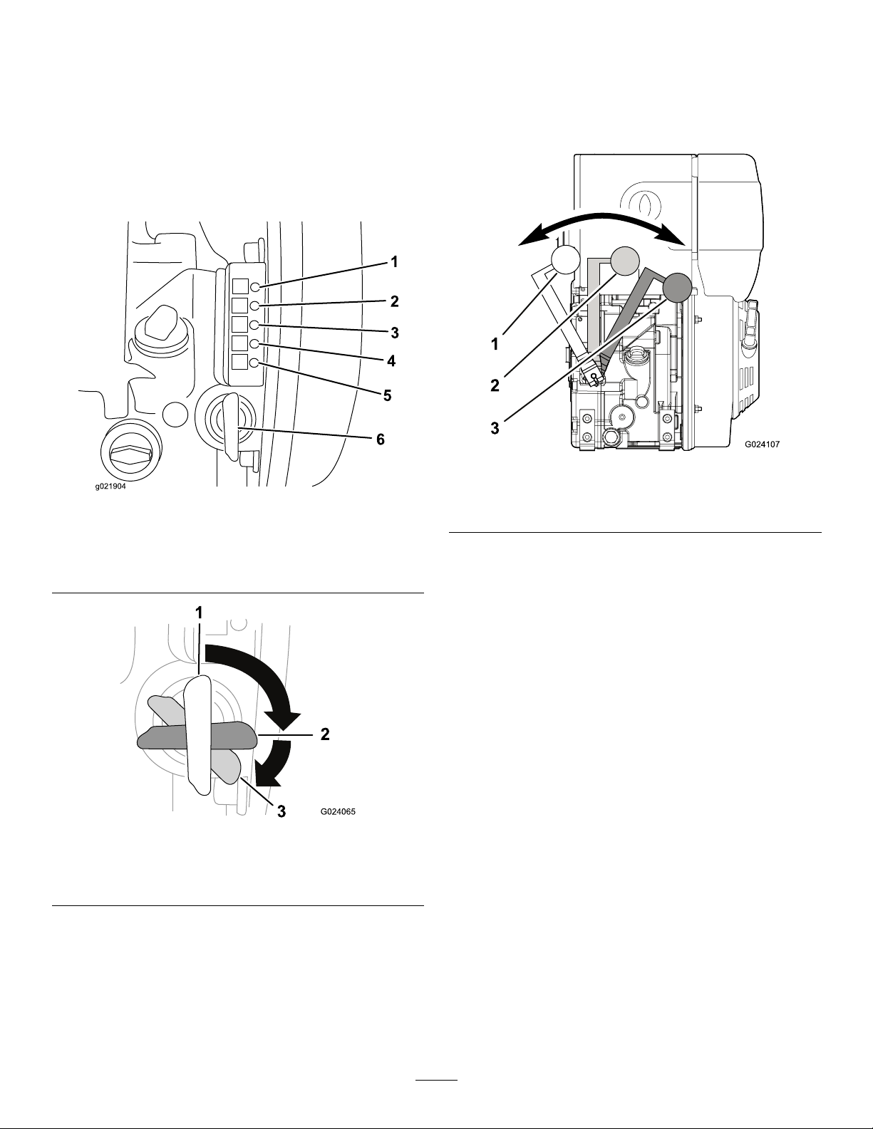
Electric-startSwitch
1
2
3
G024065
*)
1
G024107
2
3
Speed-controlHandle
Theelectric-startswitch(Figure12)allowstheoperatorof
themachinetostarttheengine.Thisswitchislocatedonthe
frontoftheengine.RotatetheignitionswitchtotheStart
positiontostarttheengine.Rotatetheignitionswitchto
theRunpositiontoallowtheenginetorun.Afteryoustop
theenginewiththespeed-controlhandle,rotatetheignition
switchtotheOffposition.
Note:Theswitchdoesnotstoptheengine.
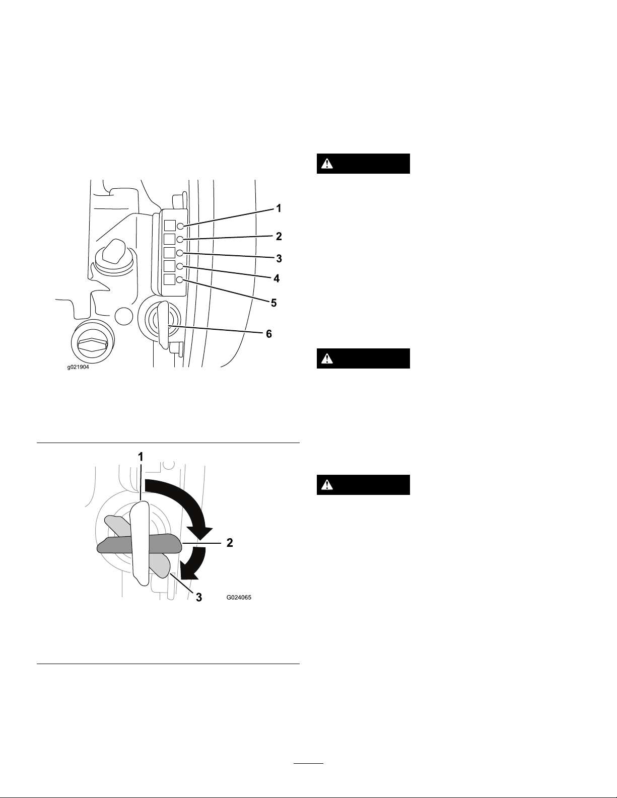
Thespeed-controlhandle(Figure14)controlstheengine
speedandalsostopstheengine.Movingitallthewaytothe
left(counterclockwise)stopstheengine.Movingittothe
right(clockwise)increasestheenginespeed.
Figure14
Figure12
1.Engine-runlight4.Engine-temperaturelight
2.Battery-chargelight5.Engine-preheatlight
3.Oil-pressurewarninglight
1.Offposition3.Startposition
2.Runposition
6.Ignitionswitch
Figure13
1.Offposition
2.Medium-speedposition
3.Fast-speedposition
Recoil-startHandle
Ifthebatteryisnotcharged,youcanstarttheenginewiththe
recoil-starthandle.T ostarttheengine,pulltherecoil-start
handle(Figure11)quicklytoturntheengineover.The
enginecontrolsdescribedabovemustallbesetcorrectlyfor
theenginetostart.
11
Page 12

Specications
1 2
G024050
Mixer
FlowrateLengthWidthHeightWeight
Upto1249L/minute(330
gallons/minute)
Tanks
141cm(55.4inches)90cm(35.3inches)116.2cm(45.8inches)204kg(450lb)
Capacity
1893L(500USgallons)203.2cm(80.0inches)78.7cm(31.0inches)177.8cm(70.0inches)241kg(532lb)
3785L(1000USgallons)257.2cm(101.3inches)108.6cm(42.8inches)191.1cm(75.3inches)397kg(876lb)
LengthWidthHeightDryweight
Operation
PreparingtoUsetheMachine
•Reviewallofthesafetydecalsonthemachine.
•Useadustmaskorrespirator.
•Ensurethatyouarefamiliarwiththesafetyregulations
andshutdownproceduresdescribedintheOperator’s
Manualandtheengineowner’smanual.
•Ensurethatallguardsareinplaceandingoodcondition.
•Checkthefuelandoillevelsoftheengine.
•Whenpreparingtomixuid:
1.Movethemachinetoaleveljob-sitesurface.
2.Ensurethatthehosesareconnectedappropriately
andsecurely.
GroundingtheMixerandthe Tank
Groundthemixingsystem.
Connectabraidedgroundingstraporajumpercable(sold
separately)fromthemixerframetotheground.
1.Closedposition2.Openposition
Beforestartingtheengine,ensurethatthehoppervalveand
thetransfervalvearebothclosed,andthesuctionvalveand
thecirculationvalvearebothopen(Figure10).
AddingFuel
•Theenginerunsonclean,fresh,ultra-low-sulfurdiesel
fuel.
•Purchasefuelinquantitiesthatcanbeusedwithin30days
toensurefuelfreshness.
•Usesummer-gradedieselfuel(Number2-D)at
temperaturesabove-7°C(20°F)andwinter-gradediesel
fuel(Number1-DorNumber1-D/2-Dblend)below
-7°C(20°F).
Figure15
AdjustingtheValves
WARNING
Ifyouruntheenginewhenthemixingvalvesarenot
adjustedasdirected,thepumpcandirectuidout
throughthehopperandpushthegrateintotheair.
Ensurethatthemixingvalvesareadjusted
appropriatelyandthatthegrateistetheredtothe
hopper,beforestartingtheengine.
Toopenavalve,turnthehandlesothatitisinlinewith
thepipe.Tocloseavalve,turnthehandlesothatitis
perpendiculartothepipe(Figure15).
•Nevermixkerosene,usedengineoil,orresidualfuels
withthedieselfuel.
•Donotstorefueleitherinthefueltankorfuelcontainers
overthewinter.
•Fueladditivesarenotrecommended.Somefueladditives
maycausepoorengineperformance.
12
Page 13

DANGER
WARNING
Incertainconditions,fuelisextremelyammable
andhighlyexplosive.Areorexplosionfromfuel
canburnyouandothersandcandamageproperty.
Useonlydieselfuel.Fillingthefueltankwith
gasolinemayresultinare.
•Fillthefueltankandstorefuelina
well-ventilatedarea.
•Neverllthefueltankwhiletheengineis
running.
•Donotllthefueltankcompletelyfull.This
emptyspaceinthetankallowsfueltoexpand.
•Neversmokewhenhandlingfuel,andstayaway
fromanopenameorwherefuelmaybeignited
byaspark.
•Storefuelinanapprovedcontainerandkeepit
outofthereachofchildren.Donotbuymore
thana30-daysupplyoffuel.
•Donotoperatewithouttheentireexhaust
systeminplaceandinproperworkingcondition.
Fuelisharmfulorfatalifswallowed.Long-term
exposuretovaporscancauseseriousinjuryand
illness.
•Avoidprolongedbreathingofvapors.
•Keepyourfaceawayfromthenozzleandthe
fueltankorconditioneropening.
•Keepfuelawayfromyoureyesandskin.
Important:Donotmixoilwithdiesel.
Dieselfuelshouldcomplywiththefollowingspecication.
Thetablelists7worldwidespecicationsfordieselfuels.
DieselFuelSpecications
Number2-D,Number1-D,
ASTMD975-94
EN590:96EuropeanUnion
ISO8217DMX
BS2869-A1orA2
JISK2204GradeNumber2
KSM-2610
GB252China
Location
USA
International
UnitedKingdom
Japan
Korea
DANGER
Incertainconditionsduringfueling,static
electricitycanbereleasedcausingasparkwhich
canignitethefuelvapors.Areorexplosionfrom
fuelcanburnyouandothersandcandamage
property.
•Alwaysplacefuelcontainersonthegroundaway
fromyourvehiclebeforelling.
•Donotllfuelcontainersinsideavehicleoron
atruckortrailerbed,becauseinteriorcarpets
orplastictruck-bedlinersmayinsulatethe
containerandslowthelossofanystaticcharge.
•Whenpractical,removefuel-poweredequipment
fromthetruckortrailerandfueltheequipment
withthewheelsontheground.
•Ifthisisnotpossible,thenrefuelsuch
equipmentonatruckortrailerfromaportable
container,ratherthanfromafuel-dispenser
nozzle.
•Ifafuel-dispensernozzlemustbeused,keepthe
nozzleincontactwiththerimofthefueltank
orcontaineropeningatalltimesuntilfuelingis
complete.
UsingFuelStabilizer/Conditioner
Useadieselfuelstabilizer/conditionerinthemachineto
keepthefuelfreshduringstorageof90daysorless.Ifyou
arestoringthemachineforlonger,drainthefueltank;refer
toStorage(page23).
Important:Donotusefueladditivescontaining
methanolorethanol.
Addthecorrectamountoffuelstabilizer/conditionertothe
fuel,andfollowthedirectionsofthemanufacturer.
Note:Fuelstabilizer/conditionerismosteffectivewhen
mixedwithfreshfuel.
FillingtheFuelTank
Capacity:5.0L(5.3USqt)
1.Stoptheengine,allowtheenginetocool,andensure
thatthemachineisonalevelsurface.
2.Cleanaroundthefuel-tankcapandremoveit(Figure
16).
13
Page 14

Note:Iftheambienttemperatureisabove35°C(95°F),use
2
3
1
G024106
SAE5W -40orSAE10W -40
1.Ensurethatthemachineisonalevelsurface.
2.Runtheengineforafewminutestowarmtheoil.
Note:Warmoilowsbetterandcarriesmore
contaminants.
3.Stoptheengineandwaitforallmovingpartstostop.
Figure16
1.Fuel-tankcap
3.Adddieselfueltothefueltank(Figure17).
Important:Donotoverllthefueltank.
Figure17
4.Cleanaroundthedipstick(
cannotfallintothellerholeanddamagetheengine.
Figure18
1.Minimumoillevel3.Dipstick
2.Maximumoillevel
5.Unscrewthedipstickandwipetheendclean(Figure
18).
6.Screwthedipstickfullyontothellertube(Figure18).
Figure18)sothatdirt
4.Installthefuel-tankcapsecurely .
5.Wipeupanyfuelthatmayhavespilled.
CheckingtheEngine-oilLevel
ServiceInterval:Beforeeachuseordaily
7.Unscrewthedipstickagainandlookattheend.
Note:Iftheengineoillevelislow ,slowlypouronly
enoughoilintothellertubetoraisetheleveltothe
maximummarkonthedipstick.
StartingandStoppingthe
Important:Use4-cycleengineoilthatmeetsorexceeds
thefollowingguidelinesandclassications:
•APIServiceCategoriesCH-4,CI-4,CJ-4orhigher
•ACEAServiceCategoriesE-3,E-4,andE-5
AuthorizedT oroDealer.
CrankcaseCapacity:1.5L(1.59USqt)
Important:Iftheoillevelinthecrankcaseistoolow
ortoohighandyouruntheengine,youmaydamage
theengine.Thistypeofdamageisnotcoveredbythe
warranty.
Viscosity:SAE5W -30
Note:T oroPremiumEngineOilisavailablefromyour
Engine
WARNING
Ifyouruntheenginewhenthemixingvalvesarenot
adjustedasdirected,thepumpcandirectuidout
throughthehopperandpushthegrateintotheair.
Ensurethatthemixingvalvesareadjusted
appropriatelyandthatthegrateistetheredtothe
hopper,beforestartingtheengine.
Important:Becausetheuidcoolsthepumpseal,the
pumpmayoverheatifyouruntheenginewithoutuid
14
Page 15
inthemixer.Donotruntheenginewithoutuidinthe
1
2
3
G024065
mixer.
StartingtheEngine
1.Movethespeed-controlhandletotheright(Figure14);
refertoSpeed-controlHandle(page11).
Note:Ifsmokecomesfromtheexhaust,movethe
speed-controlhandletotheleft.
2.RotatetheignitionswitchtotheRunposition(Figure
19);refertoElectric-startSwitch(page11).
theelectricstarterfortoolongwilloverheatthe
startermotorandcandamageit.
Note:Ifafterseveralattemptsofstartingthe
exhaustbeginstoemitwhitesmoke,movethespeed
adjustmentleverallthewaytotheleft,andpullthe
recoil-starthandleoutslowly5times.Repeatthe
startingprocedure.
StoppingtheEngine
WARNING
Inanemergencysituation,stoptheengine
immediately.
1.Movethespeed-controlhandletotheStopposition
(
Figure14);refertoSpeed-controlHandle(page11).
2.Rotatetheelectric-startswitchtotheOffposition;
referto
Important:KeeptheignitionswitchintheStop
position.LeavingtheignitionswitchintheRunposition
whiletheengineisoffwilldischargethebattery.
Electric-startSwitch(page11).
Figure19
1.Engine-runlight4.Engine-temperaturelight
2.Battery-chargelight5.Engine-preheatlight
3.Oil-pressurewarninglight
1.Stopposition3.Startposition
2.Runposition
3.TurntheignitionswitchtotheStartposition,andhold
itthereuntiltheenginestarts(Figure20).
Important:Iftheenginedoesnotstartwithin
15seconds,releasethekey ,andwaitatleast10
secondsbeforeoperatingthestarteragain.Using
6.Ignitionswitch
Figure20
MixingtheFluid
WARNING
Ifyouruntheenginewhenthemixingvalvesarenot
adjustedasdirected,thepumpcandirectuidout
throughthehopperandpushthegrateintotheair.
Ensurethatthemixingvalvesareadjusted
appropriatelyandthatthegrateistetheredtothe
hopper,beforestartingtheengine.
WARNING
Drillinguidcanbeveryslippery.Ifthereare
drilling-uidcomponentsonthegroundorother
surfaces,someonecouldslipandfall,resultingin
seriouspersonalinjury.
Wearslip-resistantfootwearandusecautionwhile
workinginareaswithdrilling-uidcomponents.
Thereisavarietyofmaterialsavailableforcreatingdifferent
typesofdrillinguid.Matchthedrillinguidtosuitthe
needsofthesoilconditions,andfollowthemanufacturer’s
instructionsthatareprintedonthepackagingoftheproduct.
Note:Theorderinwhichyouaddthecomponentsof
theuidisimportant.Followtheinstructionsofthe
manufacturers.
1.Ensurethatthegrateistetheredtothehopperandthat
thevalvesareadjustedappropriately;referto
theValves(page12).
2.Starttheengine;refertoStartingtheEngine(page15).
Adjusting
15
Page 16

3.Addtheappropriateamountofwatertothetank
1
2
3
G024042
throughthehatch(Figure9).
Ifyouareusingwaterfromaditchorapond,placea
verynescreenovertheinletofthehosetoprevent
unwantedmaterialfromenteringthemixingsystem.
Ensurethatthereisenoughroomforadditivesinthe
mixingsystem.
4.TestthepHofthewater.Ifitisbelow8,addsodaash
untilthepHis8orhigher.
Note:SuppliesfortestingpHareavailablewhere
swimming-poolsuppliesaresold.
5.Slightlyopenthevalveatthebottomofthehopper.
Note:Thevalveworksmoreeffectivelywhenitis
openonlyslightly;itcreatesavacuumeffectthatallows
thedrycomponentstoenterthemixeratafasterrate.
6.Addtheappropriateamountofbentonitetothe
hopper.
Note:Addthebentoniteslowlytoavoidclumping—1
baginapproximately3to5minutes.Openthetank
coverandlooktoensurethattheuidcomponents
aremixingcorrectly.Ifyouseeanyclumps,addthe
componentsataslowerrate.
7.Afteryouhaveaddedtheappropriateamountof
bentonite,addanypolymersthattheparticularsoil
conditionsrequire.
8.Lastly,addanyotherliquidsthatthesoilconditions
require.
9.Allowthemachinetothoroughlymixtheuidfor
severalminutes.
PumpingtheFluidtotheDrill
DANGER
Theuidmixerwillbeelectriedifthehoseis
attachedtothedrillandthedrillstrikesanelectrical
line.Contactingtheuidmixerduringanelectrical
strikemaycausebodilyharm.
•Ensurethattheuid-mixerframeandthetank
framearebondedtothegroundrod.
•Ifastrikeoccurs,stayawayfromtheuidmixer
andthedrill.Donotcontactthemixeruntilthe
electricalstrikehasbeencorrected.
Figure21
2.Openthetransfervalvetoallowtheuidtoowto
thedrill.
Note:Keepthecirculationvalveopensothattheuid
continuestocirculateinthemixer.
Important:Unlessyouareusingadditionalequipment
tothoroughlycleanthedrillinguid,donotcirculate
theuseduidthroughthemixer.Doingsomaydamage
thepump.
Disposeoftheuseddrillinguid,aswellastheunuseduid
leftinthetank,accordingtoenvironmentalregulations.
DrainingtheTank
Todrainthetank,removethedrainplugfromthesideofthe
tankframe(Figure9).
Disposeoftheuseddrillinguid,aswellastheunuseduid
leftinthetank,accordingtoenvironmentalregulations.
1.Usethetransferhose(provided)toconnectthemixer
andthedrill.
Note:Themixerhasamalecamlocktting(Figure
21)locatedafterthetransfervalve.
16
Page 17

ProtectingtheMachinefrom
1
G023837
Freezing
1.Ensurethatallthevalvesareopen.
2.Rinsethetankwithcleanclearwaterandthenpump
itthroughthesystem,removingasmuchoftheslurry
mixinthesystemaspossible.
3.Drainthetank;referto
4.Drainanyremaininguidfromthepumpbyremoving
thedrainpluginthebottomofthepump(Figure22).
1.Drainplug
5.Topreventthevalveatthebaseofthehopperfrom
freezingaroundtheedges,eitherleavethevalveopen
halfway,orclosethevalveandpouranenvironmentally
friendlyantifreezeintothehopperuntilabout51mm
(2inches)ofuidcoversthevalve.
DrainingtheTank(page16).
Figure22
OperatingTips
•Usethecorrectuidformulaforthesituationandthe
soilconditions.
•Whenusinguidwithanypolymerinit,donotover-mix
theuid,asover-mixingcanlowertheviscosityofit.
Partiallyclosethecirculationvalve,ordecreasetheengine
speed;refertoSpeed-controlHandle(page11).
•Sometypesofpolymerspreventadditionalbentonite
frommixingwiththeuid.Iftheuidcontainspolymer
andyouneedmoreuid,drainthemixerandmakeanew
batchofuid.
•Ensurethatthevalvesareadjustedappropriatelywhen
themachineisrunning;referto
(page12)
.
•Cleanthedrillinguidoutandrinsetheinsideofthe
hosesandthetankwithwatertopreventtheuidfrom
dryingupandpluggingthelines.
•Keepthehopperinletcleantopreventthedrymixfrom
mixingwithrainordewandcausingaplug.
AdjustingtheValves
17
Page 18

Maintenance
G023836
Important:Beforeperforminganymaintenanceprocedures,rststoptheengineandwait5minutestoallow
allmovingpartstocometoacompletestopandcool.
RecommendedMaintenanceSchedule(s)
MaintenanceService
Interval
Aftertherst25hours
Beforeeachuseordaily
Aftereachuse
Every20hours
Every50hours
Every100hours
Every300hours
Every500hours
Important:Refertoyourengineowner'smanualforadditionalmaintenanceprocedures.
Premaintenance
MaintenanceProcedure
•Changetheengineoil.
•Checktheengine-oillevel.
•Inspecttheair-cleanerelement.
•Cleanthemachine.
•Checkthewatertrap.
•Cleantheair-cleanerelement.Cleanitmorefrequentlyindustyoperatingconditions.
•Lubricatethepump.
•Changetheengineoil.
•Checkthebatterycableconnections.
•Replacetheair-cleanerelement.Replaceitmorefrequentlyindustyoperating
conditions.
•Replacethefuellter.
Lubrication
Procedures
PreparingtheMachinefor Maintenance
1.Parkthetransportvehicleonalevelsurfaceandchock
thetires,orremovethemachinefromthetransport
vehicle.
2.Ensurethattheengineandmuferarecool.
3.Turntheelectric-startswitchtotheOffposition.
LubricatingthePump
ServiceInterval:Every100hours
GreaseType:NLGI#1heavy-dutyEPgrease(Toropart
505-162)
Useagreaseguntopumpgreaseintothegreasettingonthe
sideofthepump(
Figure23).
Figure23
18
Page 19

EngineMaintenance
1
G024102
2 3 4
1
G024103
ServicingtheAirCleaner
ServiceInterval:Beforeeachuseordaily—Inspectthe
air-cleanerelement.
Every50hours—Cleantheair-cleanerelement.Clean
itmorefrequentlyindustyoperatingconditions.
ServicingtheEngineOil
ServiceInterval:Aftertherst25hours
Every100hours
Important:Use4-cycleengineoilthatmeetsorexceeds
thefollowingguidelinesandclassications:
•APIServiceCategoriesCH-4,CI-4,CJ-4orhigher
•ACEAServiceCategoriesE-3,E-4,andE-5
Every300hours/Yearly(whichevercomes
rst)—Replacetheair-cleanerelement.Replaceit
morefrequentlyindustyoperatingconditions.
Important:Donotoperatetheenginewithouttheair
lterassembly;extremeenginedamagewilloccur.
1.Setthethrottletoslow,stoptheengine,andwaitfor
allmovingpartstostop.
2.Unscrewthecovernutandremovethecover(Figure
24).
Note:Becarefultopreventdirtanddebrisfrom
fallingintothebase.
Note:T oroPremiumEngineOilisavailablefromyour
AuthorizedT oroDealer.
CrankcaseCapacity:1.5L(1.59USqt)
Important:Iftheoillevelinthecrankcaseistoolow
ortoohighandyouruntheengine,youmaydamage
theengine.Thistypeofdamageisnotcoveredbythe
warranty.
Viscosity:SAE5W -30
Note:Iftheambienttemperatureisabove35°C(95°F),use
SAE5W -40orSAE10W -40
ChangingtheEngineOil
1.Ensurethatthemachineisonalevelsurface.
2.Runtheengineforafewminutestowarmtheoil.
Note:Warmoilowsbetterandcarriesmore
contaminants.
3.Stoptheengineandwaitforallmovingpartstostop.
4.Placeasuitablereceptacleundertheoil-drainplug
Figure25).
(
Figure24
1.Covernut
2.Cover
3.Unscrewthelternutandremovetheelement(Figure
24).
4.Inspecttheelement,andreplaceitifitisdamagedor
excessivelydirty.
Note:Nevertrytobrushdirtoffthepaperelement;
brushingforcesthedirtintothebers.
5.Wipedirtfromthebaseandthecoverwithamoistrag.
6.Installtheaircleanerpaperelementandensurethat
itisproperlypositioned.
7.Securelyinstallthecoverwiththecovernut.
3.Filternut
4.Filterelement
Figure25
1.Oil-drainplug
5.Removethedrainplug.
19
Page 20

6.Cleanaroundthedipstick(Figure26)sothatdirt
2
3
1
G024106
1
G024105
cannotfallintothellerholeanddamagetheengine.
Figure26
1.Minimumoillevel3.Dipstick
2.Maximumoillevel
7.Unscrewthedipstickandwipetheendclean.
FuelSystem
Maintenance
CheckingtheWaterTrap
ServiceInterval:Every20hours
1.Setthethrottletoslow,stoptheengine,andwaitfor
allmovingpartstostop.
2.Loosenthewater-trapbolt3to4rotations(Figure27).
8.Screwthedipstickfullyontothellertube.
9.Unscrewthedipstickagainandlookattheend.
Note:Iftheengine-oillevelislow,slowlypouronly
enoughoilintothellertubetoraisetheleveltothe
maximummarkonthedipstick.
Figure27
1.Water-trapbolt
3.Useatransparentcontainertocatchthedripsfrom
thebolt.
Note:Becausewaterisdenserthandieselfuel,any
waterthatispresentwillemergerst.
4.Assoonasdieselfuelemerges,tightenthewater-trap
bolt.
5.Disposeofthewaterandthefuelaccordingto
environmentalregulations.
20
Page 21

ReplacingtheFuelFilter
1
G024104
2
ServiceInterval:Every500hours
Note:Theenginehasadual-ltersystem.Replaceonlythe
externallter.
1.Stoptheengine,removethekey,andwaitforthe
enginetocooldown.
2.Removethefuel-tankcap.
3.Pullthefuellteroutofthefueltank(Figure28).
ElectricalSystem
Maintenance
ReplacingtheBattery
1.Removethecoverofthebatterybox.
2.Disconnectthenegative(black)groundcablefromthe
batterypost.
Note:Thelteristetheredtothefuel-tankcap.
Figure28
1.Fuel-tankcap
4.Pullthelteroffthefuelhose.
2.Fuellter
WARNING
Incorrectbatterycableroutingcoulddamage
themachineandcables,causingsparks.
Sparkscancausethebatterygasestoexplode,
resultinginpersonalinjury.
•Alwaysdisconnectthenegative(black)
batterycablebeforedisconnectingthe
positive(red)cable.
•Alwaysconnectthepositive(red)battery
cablebeforeconnectingthenegative
(black)cable.
WARNING
Batteryterminalsormetaltoolscouldshort
againstmetalmachinecomponents,causing
sparks.Sparkscancausethebatterygasesto
explode,resultinginpersonalinjury.
•Whenremovingorinstallingthebattery,
donotallowthebatteryterminalstotouch
anymetalpartsofthemachine.
•Donotallowmetaltoolstoshortbetween
thebatteryterminalsandmetalpartsof
themachine.
5.Installanewlterintothefuelhose.
6.Placethelterintothefueltank,andinstallthe
fuel-tankcap.
3.Removethepositive(red)batterycable.
4.Removethebattery.
5.Placethenewbatteryinthetray .
6.Installthepositive(red)batterycabletothepositive
(+)batteryterminal,andtightenthenutontothebolt.
7.Installthenegative(black)groundcabletothenegative
(-)batteryterminal,andtightenthenutontothebolt.
8.Installthecoverofthebatterybox,andsecureitwith
thestrap.
9.Recycletheoldbatteryatanauthorizedfacility.
21
Page 22

ChargingtheBattery
CheckingandCleaningthe
WARNING
Chargingthebatteryproducesgasesthatcan
explode,seriouslyinjuringyouorbystanders.
Neversmokenearthebattery,andkeepsparksand
amesawayfromthebattery.
Important:Alwayskeepthebatteryfullycharged.This
isespeciallyimportanttopreventbatterydamagewhen
thetemperatureisbelow0°C(32°F).
1.Chargethebatteryfor10to15minutesat25to30
amps,or30minutesat10amps.
2.Whenthebatteryisfullycharged,unplugthecharger
fromtheelectricaloutlet,anddisconnectthecharger
leadsfromthebatteryposts(Figure29).
3.Installthebatteryinthemachineandconnectthe
batterycables;refertoReplacingtheBattery(page21).
Important:Donotrunthemachinewiththe
batterydisconnected;electricaldamagemay
occur.
Battery
ServiceInterval:Every100hours—Checkthebatterycable
connections.
Keepthetopofthebatteryclean.Ifthemachineisstoredin
alocationwheretemperaturesareextremelyhigh,thebattery
willdischargemorerapidlythanifthemachineisstoredin
acoolerlocation.
Keepthetopofthebatterycleanbywashingitwithabrush
dippedinammoniaorasolutionofsodiumbicarbonate.
Flushthetopsurfacewithwateraftercleaning.Donot
removethellcapwhilecleaningthebattery.
Thebatterycablesmustbetightontheterminalstoprovide
goodelectricalcontact.
Ifcorrosionoccursatthebatteryterminals,disconnectthe
cables,negative(-)cablerst,andscrapetheclampsand
terminalsseparately.Connectthecables,positive(+)cable
rst,andcoattheterminalswithpetroleumjelly.
Figure29
1.Positivebatterypost
2.Negativebatterypost
Ifthebatterynolongerholdsacharge,replaceit;referto
ReplacingtheBattery(page21).
3.Red(+)chargerlead
4.Black(-)chargerlead
22
Page 23

Cleaning
Storage
CleaningtheMachine
Regularcleaningandwashingwillincreasethelifespanof
themachine.Cleanthemachineaftereachuse,beforethe
dirthardens.
Ensurethatthefuel-tankcapandoilcap/dipstickaresecure
toavoidgettingwaterintheengine.
Usecarewhenusingahigh-pressuresprayer,becauseitcan
damagewarningdecals,instructionsigns,andtheengine.
StoringtheMachine
Forstorageover30days,preparethemachineasfollows:
1.Removedirtandgrimefromtheexternalpartsofthe
entiremachine,especiallytheengine.Cleandirtand
debrisfromtheoutsideoftheenginecylinder-head
nsandblowerhousing.
Important:Youcanwashthemachinewithmild
detergentandwater.
2.Conditionthefuelsystemasfollows:
A.Addapetroleum-basedstabilizer/conditionerto
fuelinthetank.Followthemixinginstructions
fromthestabilizermanufacturer.Donotusean
alcohol-basedstabilizer(ethanolormethanol).
Important:Donotstore
stabilizer/conditionedfuelover90days.
Note:Fuelstabilizer/conditionerismost
effectivewhenmixedwithfreshfuelandusedat
alltimes.
B.Runtheenginefor5minutestodistributethe
conditionedfuelthroughthefuelsystem.
Important:Donotruntheenginewithout
waterinthetank,orthepumpwillbe
damaged.
C.Stoptheengine,allowittocool,anddrainthe
fueltankusingapump-typesiphon.Disposeof
fuelproperly;recycleitaccordingtolocalcodes.
D.Starttheengineandrunituntilitstops.
E.Choketheengine.
F.Startandruntheengineuntilitwillnotstartagain.
3.Servicetheaircleaner;referto
Cleaner(page19)
4.Changetheenginecrankcaseoil;referto
EngineOil(page19).
5.Greasethemachine;refertoLubricatingthePump
(page18).
6.Checkandtightenallbolts,nuts,andscrews.Repairor
replaceanypartthatisdamaged.
7.Paintallscratchedorbaremetalsurfaces.Paintis
availablefromyourAuthorizedToroDealer.
8.Storethemachineinaclean,drygarageorstoragearea.
.
ServicingtheAir
Servicingthe
9.Coverthemachinetoprotectitandkeepitclean.
23
Page 24

Troubleshooting
Problem
Theenginedoesnotstart.
Theenginelackspowerorrunsrough.
Theuiddoesnotcirculateatfull
efciency.
PossibleCauseCorrectiveAction
1.TheengineOn/OffswitchisintheOff
position.
2.Thefueltankisempty.2.Fillthefueltankwithfreshfuel.
3.Theenginecontainsbadoroldfuel.3.Drainthefueltank.Fillthefueltank
1.Theairlterisrestricted.1.Cleanorreplacetheair-lter
2.Theenginecontainsbadoroldfuel.2.Drainthefueltank.Fillthefueltank
3.Thereiswaterorcontaminationinthe
fuel.
4.Thefuellineisrestricted.4.Cleanthefuellter.
5.Thereistoomuchoilintheengine
crankcase.
1.Thepumpinletisclogged.
1.RotatetheswitchtotheOnposition.
freshfuel.
element(s).
withfreshfuel.
3.Drainthefueltank.Fillthefueltank
withfreshfuel.
5.Draintheoiltotheproperlevel.
1.ContactanAuthorizedServiceDealer.
24
Page 25

Notes:
25
Page 26

Notes:
26
Page 27

Notes:
27
Page 28

TheToroUndergroundWarranty
ALimitedWarranty
Underground
Equipment
ConditionsandProductsCovered
TheToroCompanyanditsafliate,ToroWarrantyCompany,pursuant
toanagreementbetweenthem,jointlywarrantyourT oroUnderground
Equipment(“Product”)tobefreefromdefectsinmaterialsorworkmanship.
Whereawarrantableconditionexists,wewillrepairtheProduct
atnocosttoyouincludingdiagnostics,labor,andparts.
ThefollowingwarrantyappliesfromthedatetheProductisdeliveredto
theoriginalretailpurchaserorrentalowner.
ProductsWarrantyPeriod
RT600,RT1200,DD2024,and
DD4045
AllOtherEnginePoweredBase
UnitsandFluidMixers
AllSerializedAttachments
RockHammer6months
Engines
2yearsor1500operatinghours,
whicheveroccursrst
1yearor1000operatinghours,
whicheveroccursrst
1year
Throughenginemanufacturers:
2yearsor2000operatinghours,
whicheveroccursrst
InstructionsforObtainingWarrantyService
YouareresponsiblefornotifyingtheUndergroundDealerfromwhomyou
purchasedtheProductassoonasyoubelieveawarrantablecondition
exists.IfyouneedhelplocatingaUndergroundDealer,orifyouhave
questionsregardingyourwarrantyrightsorresponsibilities,youmay
contactusat:
ToroCustomerCare
ToroWarrantyCompany
811 1LyndaleAvenueSouth
Bloomington,MN55420-1196
TollFreeat855-493-0088(U.S.Customers)
1-952-948-4318(InternationalCustomers)
OwnerResponsibilities
AstheProductowner,youareresponsibleforrequiredmaintenance
andadjustmentsstatedinyourOperator'sManual.Failuretoperform
requiredmaintenanceandadjustmentscanbegroundsfordisallowinga
warrantyclaim.
ItemsandConditionsNotCovered
Notallproductfailuresormalfunctionsthatoccurduringthewarranty
periodaredefectsinmaterialsorworkmanship.Thiswarrantydoesnot
coverthefollowing:
•Productfailureswhichresultfromtheuseofnon-Tororeplacement
parts,orfrominstallationanduseofadd-on,ormodiednon-T oro
brandedaccessoriesandproducts.Aseparatewarrantymaybe
providedbythemanufactureroftheseitems.
•Productfailureswhichresultfromfailuretoperformrecommended
maintenanceand/oradjustments.Failuretoproperlymaintainyour
ToroproductpertheRecommendedMaintenancelistedinthe
Operator’sManualcanresultinclaimsforwarrantybeingdenied.
•ProductfailureswhichresultfromoperatingtheProductinan
abusive,negligent,orrecklessmanner.
•Partssubjecttoconsumptionthroughuseunlessfoundtobe
defective.Examplesofpartswhichareconsumed,orusedup,during
normalProductoperationinclude,butarenotlimitedto:brakes,
lters,lights,bulbs,belts,tracksortires,diggingteeth,diggingbooms,
digging,drive,ortrackchains,trackpads,drivesprockets,idlers,
rollers,blades,cuttingedges,orothergroundengagingcomponents.
•Failurescausedbyoutsideinuence.Conditionsconsideredtobe
outsideinuenceinclude,butarenotlimitedto,weather,storage
practices,contamination,useofunapprovedfuels,coolants,
lubricants,additives,water,orchemicals,etc.
•Failureorperformanceissuesduetotheuseoffuels(e.g.gasoline,
diesel,orbiodiesel)thatdonotconformtotheirrespectiveindustry
standards.
•Normalnoise,vibration,wearandtear,anddeterioration.
•Normal“wearandtear”includes,butisnotlimitedto,damagetoseats
duetowearorabrasion,wornpaintedsurfaces,scratcheddecals,etc.
•Haulingexpenses,traveltime,mileage,orovertimeassociatedwith
transportingproducttotheauthorizedT orodealer.
Parts
Partsscheduledforreplacementasrequiredmaintenanceinthe
Operator’sManual,arewarrantedfortheperiodoftimeuptothescheduled
replacementtimeforthatpart.Partsreplacedunderthiswarrantyare
coveredforthedurationoftheoriginalproductwarrantyandbecomethe
propertyofT oro.Torowillmakethenaldecisionwhethertorepairany
existingpartorassemblyorreplaceit.T oromayuseremanufactured
partsforwarrantyrepairs.
MaintenanceisatOwner’sExpense
Enginetune-up,lubrication,cleaningandpolishing,replacementoflters,
coolant,andcompletingrecommendedmaintenancearesomeofthe
normalservicesT oroproductsrequirethatareattheowner’sexpense.
GeneralConditions
RepairbyanAuthorizedT oroUndergroundDealerisyoursoleremedy
underthiswarranty.
NeitherTheToroCompanynorToroWarrantyCompanyisliablefor
indirect,incidentalorconsequentialdamagesinconnectionwiththe
useoftheToroProductscoveredbythiswarranty ,includingany
costorexpenseofprovidingsubstituteequipmentorserviceduring
reasonableperiodsofmalfunctionornon-usependingcompletion
ofrepairsunderthiswarranty.ExceptfortheEmissionswarranty
referencedbelow,ifapplicable,thereisnootherexpresswarranty .
Allimpliedwarrantiesofmerchantabilityandtnessforuseare
limitedtothedurationofthisexpresswarranty .
Somestatesdonotallowexclusionsofincidentalorconsequential
damages,orlimitationsonhowlonganimpliedwarrantylasts,sothe
aboveexclusionsandlimitationsmaynotapplytoyou.Thiswarranty
givesyouspeciclegalrights,andyoumayalsohaveotherrightswhich
varyfromstatetostate.
Noteregardingenginewarranty:
TheEmissionsControlSystemonyourProductmaybecoveredby
aseparatewarrantymeetingrequirementsestablishedbytheU.S.
EnvironmentalProtectionAgency(EPA)and/ortheCaliforniaAir
ResourcesBoard(CARB).Thehourlimitationssetforthabovedonot
applytotheEmissionsControlSystemWarranty.RefertotheEngine
EmissionControlWarrantyStatementsuppliedwithyourproductor
containedintheenginemanufacturer’sdocumentationfordetails.
CountriesOtherthantheUnitedStatesorCanada
CustomerswhohavepurchasedT oroproductsexportedfromtheUnitedStatesorCanadashouldcontacttheirT oroDistributor(Dealer)toobtain
guaranteepoliciesforyourcountry ,province,orstate.IfforanyreasonyouaredissatisedwithyourUndergroundDealer’sserviceorhavedifculty
obtainingguaranteeinformation,contacttheToroimporter.
AustralianConsumerLaw:AustraliancustomerswillnddetailsrelatingtotheAustralianConsumerLaweitherinsidetheboxoratyourlocalT oro
Dealer.
374-0292RevA
 Loading...