

Page 1
FormNo.3401-823RevA
4045DirectionalDrillwithCab
ModelNo.23823—SerialNo.314000001andUp
ModelNo.23823A—SerialNo.314000001andUp
ModelNo.23823C—SerialNo.314000001andUp
ModelNo.23823W—SerialNo.314000001andUp
ModelNo.23825—SerialNo.313000001andUp
ModelNo.23825A—SerialNo.314000001andUp
ModelNo.23825C—SerialNo.314000001andUp
ModelNo.23825W—SerialNo.314000001andUp
Registeratwww.T oro.com.
OriginalInstructions(EN)
*3401-823*A
Page 2
ThisproductcomplieswithallrelevantEuropeandirectives;
fordetails,pleaseseetheseparateproductspecicDeclaration
ofConformity(DOC)sheet.
YoumaycontactTorodirectlyatwww .Toro.comforproduct
andaccessoryinformation,helpndingadealer,ortoregister
yourproduct.
WARNING
CALIFORNIA
Proposition65Warning
Thisproductcontainsachemicalorchemicals
knowntotheStateofCaliforniatocausecancer,
birthdefects,orreproductiveharm.
Dieselengineexhaustandsomeofits
constituentsareknowntotheStateof
Californiatocausecancer,birthdefects,
andotherreproductiveharm.
Becauseinsomeareastherearelocal,state,orfederal
regulationsrequiringthatasparkarresterbeusedonthe
engineofthismachine,asparkarresterisavailableas
anoption.Ifyourequireasparkarrester,contactyour
AuthorizedToroServiceDealer.
GenuineT orosparkarrestersareapprovedbytheUSDA
ForestryService.
Important:ItisaviolationofCaliforniaPublic
ResourceCodeSection4442touseoroperatetheengine
onanyforest-covered,brush-covered,orgrass-covered
landwithoutasparkarrestermufermaintainedin
workingorder,ortheengineconstricted,equipped,and
maintainedforthepreventionofre.Otherstatesor
federalareasmayhavesimilarlaws.
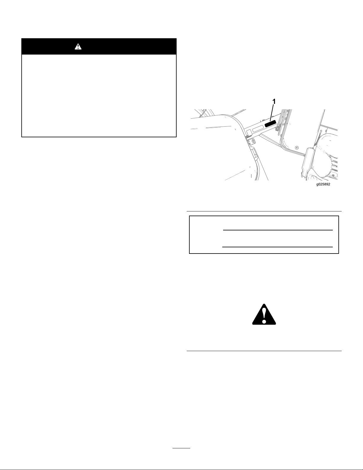
Wheneveryouneedservice,genuineT oroparts,oradditional
information,contactanAuthorizedServiceDealerorToro
CustomerServiceandhavethemodelandserialnumbersof
yourproductready.Figure1identiesthelocationofthe
modelandserialnumbersontheproduct.Writethenumbers
inthespaceprovided.
Figure1
1.Modelandserialnumberlocation
ModelNo.
SerialNo.
Theenclosed
Engine Owner's Man ual
issuppliedfor
informationregardingtheUSEnvironmentalProtection
Agency(EPA)andtheCaliforniaEmissionControl
Regulationofemissionsystems,maintenance,and
warranty.Replacementsmaybeorderedthroughthe
enginemanufacturer.
Forradiofrequencycomplianceinformation,referto
your
Compliance Statement Addendum
thatpertains
toyourcountry.
Introduction
Thismachineisadirectionaldrillintendedforunderground
drillingandpullbackoperationforutilitylinesincluding
electrical,gas,communication,water,etc.Itisdesignedto
operateawidevarietyofattachmentseachofwhichperform
aspecializedfunction.
Readthisinformationcarefullytolearnhowtooperateand
maintainyourproductproperlyandtoavoidinjuryand
productdamage.Youareresponsibleforoperatingthe
productproperlyandsafely.
Thismanualidentiespotentialhazardsandhassafety
messagesidentiedbythesafetyalertsymbol(Figure2),
whichsignalsahazardthatmaycauseseriousinjuryordeath
ifyoudonotfollowtherecommendedprecautions.
Figure2
1.Safetyalertsymbol
Thismanualuses2wordstohighlightinformation.
Importantcallsattentiontospecialmechanicalinformation
andNoteemphasizesgeneralinformationworthyofspecial
attention.
©2016—TheToro®Company
8111LyndaleAvenueSouth
Bloomington,MN55420
Contactusatwww.Toro.com.
2
PrintedintheUSA.
AllRightsReserved
Page 3

Contents
Safety...........................................................................4
Training.................................................................4
Preparation.............................................................4
GeneralOperation..................................................4
DrivingSafety.........................................................5
DrillingSafety.........................................................6
MaintenanceandStorage..........................................8
NoiseandVibrationLevels.......................................8
SafetyandInstructionalDecals.................................9
ProductOverview.........................................................21
Controls...............................................................24
OperatorPlatform..............................................24
ControlPanel.....................................................36
LeftJoystick—ModeI.........................................37
LeftJoystick—ModeII........................................38
RightJoystick—ModeI.......................................39
RightJoystick—ModeII......................................40
RearControlPanel..............................................41
DrillFrameandStabilizerControls........................42
DrivePendant....................................................43
DrillPendant......................................................44
Stake-downLevers..............................................45
Specications........................................................46
Attachments/Accessories........................................46
Operation....................................................................47
UnderstandingHorizontalDirectionalDrilling
........................................................................47
GatheringSiteInformation......................................48
PlanningtheBorePath............................................50
UnderstandingandUsingtheExit-side-lockout
System..............................................................55
PreparingtheJobSiteandtheMachine......................57
DrillingtheBore....................................................67
BackreamingandPullback.......................................71
FinishingtheJob....................................................73
UsingtheTJCApplicator........................................73
MovingaDisabledMachine.....................................75
ReplacingthePipeHolder.......................................75
PositioningtheCab(ModelwithCabonly).................76
OpeningtheDoor(ModelwithCabonly)..................76
OperatingtheAirConditioningandHeating
(ModelwithCabonly).........................................77
OperatingtheWindshieldWipers(ModelwithCab
only).................................................................77
Maintenance.................................................................78
RecommendedMaintenanceSchedule(s)......................78
PremaintenanceProcedures........................................80
OpeningtheFrontHood.........................................80
OpeningtheRear-accessDoor.................................80
UsingtheCylinderLock..........................................81
Lubrication...............................................................82
GreasingtheMachine.............................................82
EngineMaintenance..................................................84
CleaningtheCrankcase-ventTube............................84
ServicingtheAir-cleaningSystem.............................84
ServicingtheEngineOilandFilter............................86
AdjustingtheValveClearance..................................88
FuelSystemMaintenance...........................................89
DrainingWaterfromtheFuelFilter...........................89
DrainingWaterfromtheFuelTank...........................89
PrimingtheFuelSystem..........................................90
ReplacingtheFuelFilters.........................................90
CheckingtheFuelLinesandConnections..................91
DrainingandCleaningtheFuelTank.........................91
ElectricalSystemMaintenance....................................92
ServicingtheBattery...............................................92
ChargingtheBattery...............................................93
Jump-startingtheMachine.......................................93
DriveSystemMaintenance.........................................94
CheckingtheOilLevelfortheStakedown
PlanetaryDrive..................................................94
CheckingtheOilLevelfortheTracksPlanetary
Drive................................................................95
ChangingtheOilfortheTracksPlanetary
Drive................................................................95
CheckingtheOilLevelfortheRotaryMotor
PlanetaryDrive..................................................96
CheckingtheOilfortheThrustMotorPlanetary
Drive................................................................96
CheckingtheOilfortheGearboxDrive.....................97
ChangingtheOilfortheGearboxDrive.....................97
ServicingtheTracks................................................98
CoolingSystemMaintenance......................................99
CheckingtheCoolantLevelintheRadiator..............100
CheckingtheConditionofCooling-system
Components....................................................100
CheckingtheConcentrationoftheCoolant..............100
CleaningtheCoolingSystem..................................100
BeltMaintenance....................................................103
ServicingtheEngine-driveBelt...............................103
HydraulicSystemMaintenance..................................105
ServicingtheHydraulicFluid.................................105
Drilling-FluidPumpMaintenance..............................108
ServicingtheDrilling-uid-pumpOil......................108
PreparingtheDrilling-uidSystemforCold
Weather...........................................................110
CabMaintenance.....................................................112
ChangingtheCabAirFilter....................................112
FillingtheWindshield-washerFluidTank.................112
Cleaning.................................................................113
CleaningwiththeSpray-hoseAttachment................113
CleaningPlasticandResinParts..............................113
Storage......................................................................114
Troubleshooting.........................................................115
Index........................................................................118
3
Page 4

Safety
Improperuseormaintenancebytheoperatororowner
canresultininjury.Toreducethepotentialforinjury,
complywiththesesafetyinstructions,andpayattentionto
thesafetyalertsymbol,whichmeansCaution,Warning,or
Danger—“personalsafetyinstruction.”Failuretocomply
withtheinstructionsmayresultinpersonalinjuryor
death.
Important:Thismachinewasmanufacturedaccording
totheappropriateregulatorystandardsineffectatthe
timeofmanufacture.Modifyingthismachineinany
waymaycauseittobeoutofcompliancewiththose
standardsandwiththeinstructionsinthis
Man ual
madebyeitherthemanufactureroranAuthorizedToro
Dealer.
Thisproductiscapableofamputatinghandsandfeet.Follow
allsafetyinstructionstoavoidseriousinjuryordeath.
Theowner/usercanpreventandisresponsibleforaccidents
orinjuriesoccurringtopeople,ordamagetoproperty.
.Modicationstothismachineshouldonlybe
Operator’ s
Preparation
•Evaluatetheterraintodeterminewhataccessoriesand
attachmentsareneededtoproperlyandsafelyperform
thejob.Onlyuseaccessoriesandattachmentsapproved
bythemanufacturer.
•Wearappropriateclothing;includingahardhat,safety
glasses,longpants,substantialslip-resistantsafetyshoes
(rubberboots),gloves,andhearingprotection.Tieback
longhair.Donotwearjewelry.
•Inspecttheareawheretheequipmentistobeusedand
ensurethatallobjectsareremovedfromtheareabefore
use.
•Useextracarewhenhandlingfuels.Theyareammable
andvaporsareexplosive.
–Useonlyanapprovedcontainer.
–Donotremovethefuelcaporaddfuelwiththe
enginerunning.Allowtheenginetocoolbefore
refueling.Donotsmokenearthemachinewhenthe
engineisrunning.
–Donotrefuelordrainthemachineindoors.
Important:Beforeoperatinginanareawith
high-voltagelinesorcables,contacta“One-Call
SystemDirectory”service.IntheUSA,call811or
yourlocalutilitycompany .Ifyoudonotknowyour
localutilitycompany’sphonenumber,callthenational
number(USAandCanadaonly)at1-888-258-0808.Also,
contactanyutilitycompaniesthatarenotparticipants
ofthe“One-CallSystemDirectory”service.Please
refertoDrillingNearUtilityLines(page6)formore
information.
Training
•ReadtheOperator'sManualandothertrainingmaterial.
Note:Iftheoperator(s)ormechanic(s)cannotreadthis
manual,itistheowner'sresponsibilitytoexplainthis
materialtothem.
•Becomefamiliarwiththesafeoperationoftheequipment,
operatorcontrols,andsafetysigns.
•Alloperatorsandmechanicsshouldbetrained.The
ownerisresponsiblefortrainingtheusers.
•Donotletchildrenoruntrainedpeopleoperateorservice
theequipment.
•Checkthattheoperator'spresencecontrols,safety
switches,andshieldsareattachedandfunctioning
properly.Donotoperatethemachineunlesstheyare
functioningproperly.
GeneralOperation
•Donotruntheengineinanenclosedarea.
•Donotoperatewithouttheguardssecurelyinplace.Be
sureallinterlocksareattached,adjusted,andfunctioning
properly.
•Donotchangetheenginegovernorsettingoroverspeed
theengine.
•Keepawayfrommovingmachinepartsandpipes.
•Donotoperatethemachinewhenill,tired,orunderthe
inuenceofalcoholordrugs.
•Donotleavethemachinerunningunattended.Stopthe
engineandremovethekeybeforeleaving.
•Locatethepinch-pointareasmarkedonthemachineand
attachmentsandkeephandsandfeetawayfromthese
areas.
•Lightningcancausesevereinjuryordeath.Iflightning
isseenorthunderisheardinthearea,donotoperate
themachine;seekshelter.
4
Page 5
DrivingSafety
Youdrivethemachinetoandfromtheworksitewiththeuse
ofatetheredremote.Whendrivingthemachine,observethe
followingsafetyprecautions:
•Operatethedrivependantalongsidethemachineoutside
ofthedangerzone(Figure3).
•Keepallbystandersawaywhilemovingthemachine.
•Donotcarrypassengersonthemachine.
•Watchfortheturning-radiussweepofthedrillframe,as
thecenteroftheturningradiusistheendofthetrack.
•Checkforoverheadclearances(i.e.branches,doorways,
electricalwires)beforedrivingunderanyobjectsanddo
notcontactthem.
•Usecarewhendrivingthemachineonsoftorunstable
ground.
Note:Softorunevengroundcanreducestability.
•Whendrivingonaslope,theoperatorshouldbeup-slope
fromthemachine.
Note:Themachinecanbeunstableonslopes.
•Driveinaccordancewiththeweatherconditions.
•Movingthemachinewiththetetheredremotecan
beerratic;moveslowlywhenusingtheremotefor
movement.
•Usecarewhenloadingorunloadingthemachineontoa
trailer.
•Watchfortrafcwhencrossingroadways.
Note:Drivewithcautionduringadverseweather
conditions.
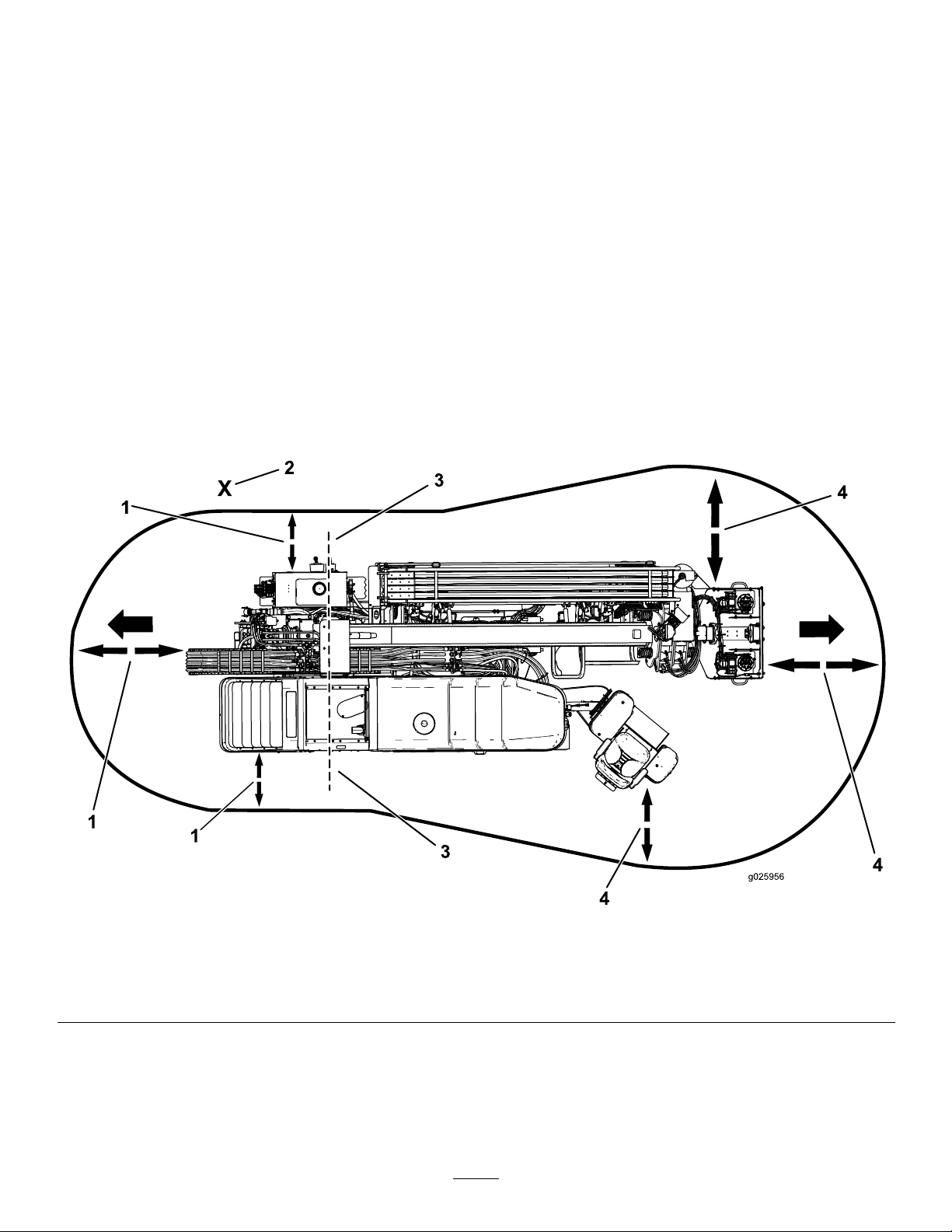
Thefollowingillustrationdisplaysthesafedistancethatmust
bekeptbyallindividualswhilemovingthemachine.
Figure3
DrivingDangerZone
1.1.8m(6ft)safetydistance
2.Operator4.3m(10ft)safetydistance
3.Turning-radiuscenter
5
Page 6
DrillingSafety
•Alwayslowerthepedestriansafetybarbeforedrilling
(Figure4).
•Ensurethatnooneapproachesapipewhileitisspinning.
Thepipecansnagonclothingandcauseamputation
ordeath.AlwaysengagetheExit-sideLockoutbefore
anyoneapproachesthefrontofthemachine,bit,reamer,
orpipe.
DrillingDangerZone
Thedangerzoneistheareawithinandaroundthemachine
whereapersonisexposedtotheriskofinjury.Thisproximity
includeswhereapersonisreachablebyoperationalmovement
ofthemachine,itsworkingdevices,auxiliaryequipment,or
swinging/fallingequipment.
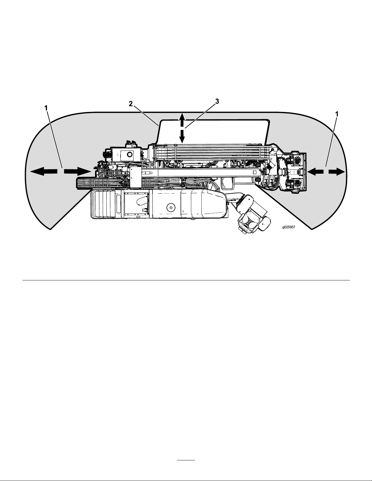
Thefollowingillustrationdisplaysthesafedistancerequired
byallindividualswhiledrilling.
Figure4
DrillingDangerZone
1.3m(10ft)safetydistance3.1.8m(6ft)safetydistance
2.Pedestriansafetybar
DrillingNearUtilityLines
Important:Beforeoperatinginanareawith
high-voltagelinesorcables,contacta“One-CallSystem
Directory”service.IntheUSA,call811oryourlocal
utilitycompany .Ifyoudonotknowyourlocalutility
company’sphonenumber,callthenationalnumber
(USAandCanadaonly)at1-888-258-0808.Also,contact
anyutilitycompaniesthatarenotparticipantsofthe
“One-CallSystemDirectory”service.
6
Page 7

UtilityLineColor
Refertothefollowingtablefortheproperutilitylineandthecorrespondingutilitylinecolor(USAandCanada).
UtilityLine
ElectricRed
Telecommunication,alarmorsignal,cables,orconduit
Naturalgas,oil,steam,petroleum,orothergaseousorammable
material
SeweranddrainGreen
DrinkingwaterBlue
Reclaimedwater,irrigation,andslurrylinesPurple
TemporarysurveymarkingsPink
ProposedexcavationlimitsWhite
ElectricalLineSafety
WARNING
Ifyouleavetheseatofthemachineortouch
anypartofthemachinewhenitischargedwith
electricity,seriousinjuryordeathcouldresult.
Donotleavetheseatofthemachineifthemachine
ischargedwithelectricity .
Intheeventofanelectricstrikethatchargesthemachine,the
Zap-AlertElectricStrikealarmsystemwillsoundforaslong
asthemachineischargedwithpower.
Note:Immediatelycontacttheproperemergencyandutility
authoritiestosecuretheareainthecasethatthemachineis
chargedandyoucannotleavetheseatofthemachine.
Note:Itispossibletostrikeautilitylinewithoutthemachine
becomingcharged.
•Thealarmwillsoundifthedrillcontactsanelectrical
powersource.
•Itislikely(butnotalwaysthecase)thatthepower-source
interrupterorbreakerwilltrip,buttoensureyoursafety,
considerthatthemachinemaybeconductingelectricity.
•Donotattempttoleavethemachine.
Important:Youwillbesafeaslongasyoudonot
leavetheseatofthemachine.
•Touchinganypartofthemachinemaygroundyou.
•Donotallowanotherindividualtotouchorapproach
themachinewhencharged.
•Thealarmmaysoundifacommunicationlineisbroken,
butuntilyouarecertain,youmustconsiderthealarmto
beanelectricstrike.
UtilityLineColor
Orange
Yellow
GasLineSafety
WARNING
Ifyoudamageagasline,animmediateexplosion
andrehazardcouldoccur.Leakinggasisboth
ammableandexplosiveandmaycauseserious
injuryordeath.
•Donotsmokewhileoperatingthemachine.
•Shutoffthemachineandremovethekey.
•Removeallindividualsfromtheworkarea.
•Immediatelycontacttheproperemergencyand
utilityauthoritiestosecurethearea.
WaterLineSafety
Ifyoudamageawaterline,apotentialoodhazard
couldoccur.
•Shutoffthemachineandremovethekey .
•Removeallindividualsfromtheworkarea.
•Immediatelycontacttheproperemergencyand
utilityauthoritiestosecurethearea.
CommunicationLineSafety
Important:RefertoElectricalLineSafety(page7)ifa
communicationlineisdamaged.
CAUTION
Ifyoudamagetheber-opticcableandlookinto
theexposedhighly-intenselight,youmayharm
youreyes.
•Shutoffthemachineandremovethekey.
•Removeallindividualsfromtheworkarea.
•Immediatelycontacttheproperemergencyand
utilityauthoritiestosecurethearea.
7
Page 8

MaintenanceandStorage
•Donottouchpartswhichmaybehotfromoperation.
Allowthemtocoolbeforeattemptingtomaintain,adjust,
orservice.
•Lowerthethrustframe,stoptheengine,andremove
thekey.Waitforallmovementtostopbeforeadjusting,
cleaning,orrepairing.
•Cleandebrisfromattachments,drives,mufers,and
enginetohelppreventres.Cleanupoilorfuelspillage.
•Lettheenginecoolbeforestoring,anddonotstorenear
aame.
•Donotstorefuelnearamesordrainindoors.
•Parkthemachineonlevelground.
•Donotallowuntrainedpersonneltoservicethemachine.
•Carefullyreleasepressurefromcomponentswithstored
energy.
–Donotrefuelthemachineindoors.
–Donotstorethemachineorfuelcontainerinside
wherethereisanopename,suchasnearawater
heaterorfurnace.
–Donotllacontainerwhileitisinsideavehicle,
trunk,pick-upbed,oranysurfaceotherthanthe
ground.
–Keepcontainernozzleincontactwiththetankduring
lling.
•UseonlygenuineTororeplacementpartstoensurethat
originalstandardsaremaintained.
•Keepyourbodyandhandsawayfrompinholeleaks
ornozzlesthatejecthighpressurehydraulicuid.Use
cardboardorpapertondhydraulicleaks;donotuse
yourhands.Hydraulicuidescapingunderpressurecan
penetrateskinandcauseinjuryrequiringsurgerywithina
fewhoursbyaqualiedsurgeonorgangrenemayresult.
•Keephandsandfeetawayfrommovingparts.Ifpossible,
donotmakeadjustmentswiththeenginerunning.
•Disconnectthebatterybeforemakinganyrepairs.
Disconnectthenegativeterminalrstandthepositive
last.Reconnectpositiverstandnegativelast.
•Chargebatteriesinanopen,wellventilatedarea,away
fromsparkandames.Unplugthechargerbefore
connectingordisconnectingitfromthebattery.W ear
protectiveclothinganduseinsulatedtools.
•Batteryacidispoisonousandcancauseburns.Avoid
contactwithskin,eyes,andclothing.Protectyourface,
eyes,andclothingwhenworkingwithabattery.
•Batterygasescanexplode.Keepcigarettes,sparksand
amesawayfromthebattery.
•Keepallpartsingood-workingconditionandallhardware
tightened.Replaceallwornordamageddecals.
•Ifanymaintenanceorrepairrequirestheframetobein
theraisedposition,securetheframeintheraisedposition
withthehydrauliccylinderlock;refertoInstallingthe
CylinderLock(page81).
•Keepnutsandboltstight.
NoiseandVibrationLevels
WARNING
Theoperatormustwearhearingprotectionwhen
operatingthemachine.Failuretowearhearing
protectionmaycausehearingloss.
SoundPressureLevel
Thisunithasasoundpressurelevelattheoperator’searof92
dBA,whichincludesanUncertaintyValue(K)of1dBA.
Soundpressurelevelwasdeterminedaccordingtothe
proceduresoutlinedinEN791.
SoundPower
Thisunithasaguaranteedsoundpowerlevelof110dBA,
whichincludesanUncertaintyValue(K)of3.75dBA.
Thesoundpowerlevelwasdeterminedaccordingtothe
proceduresoutlinedinISO4871.
•Keepequipmentingoodcondition.
•Donottamperwithsafetydevices.
•Keepthemachinefreeofgrass,leaves,orotherdebris
build-up.Cleanupoilorfuelspillage.Allowthemachine
tocoolbeforestoring.
•Useextracarewhenhandlingfuels.Theyareammable
andvaporsareexplosive.
–Useonlyanapprovedcontainer.
–Donotremovethefuelcaporaddfuelwhenthe
engineisrunning.Allowtheenginetocoolbefore
refueling.Donotsmokewhilerefuelingthemachine.
VibrationLevel
Measuredvibrationlevelforrighthand=1.8m/s
Measuredvibrationlevelforlefthand=1.3m/s
Measuredvibrationlevelforwholebody=0.03m/s
UncertaintyValue(K)=0.02m/s
Measuredvaluesweredeterminedaccordingtotheprocedures
outlinedinENISO20643.
8
2
2
2
2
Page 9
SafetyandInstructionalDecals
Safetydecalsandinstructionsareeasilyvisibletotheoperatorandarelocatednearanyareaofpotential
danger.Replaceanydecalthatisdamagedorlost.
BatterySymbols
Someorallofthesesymbolsareonyourbattery
1.Explosionhazard
2.Nore,opename,or
smoking.
3.Causticliquid/chemical
burnhazard
4.Weareyeprotection9.Flusheyesimmediately
5.ReadtheOperator's
Manual.
6.Keepbystandersasafe
7.Weareyeprotection;
8.Batteryacidcancause
10.Containslead;donot
117-2718
distancefromthebattery.
explosivegasescan
causeblindnessandother
injuries
blindnessorsevereburns.
withwaterandgetmedical
helpfast.
discard.
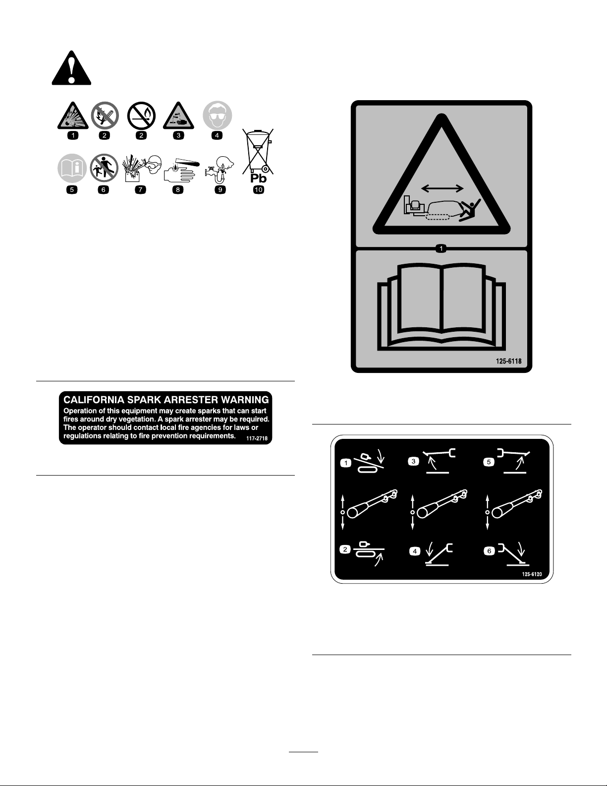
125-6118
1.Crushinghazard,machinemovement—readtheOperator’s
Manual.
125-6120
1.Lowerdrillcarriage
2.Raisedrillcarriage5.Raiserightstabilizer
3.Raiseleftstabilizer
9
4.Lowerleftstabilizer
6.Lowerrightstabilizer
Page 10
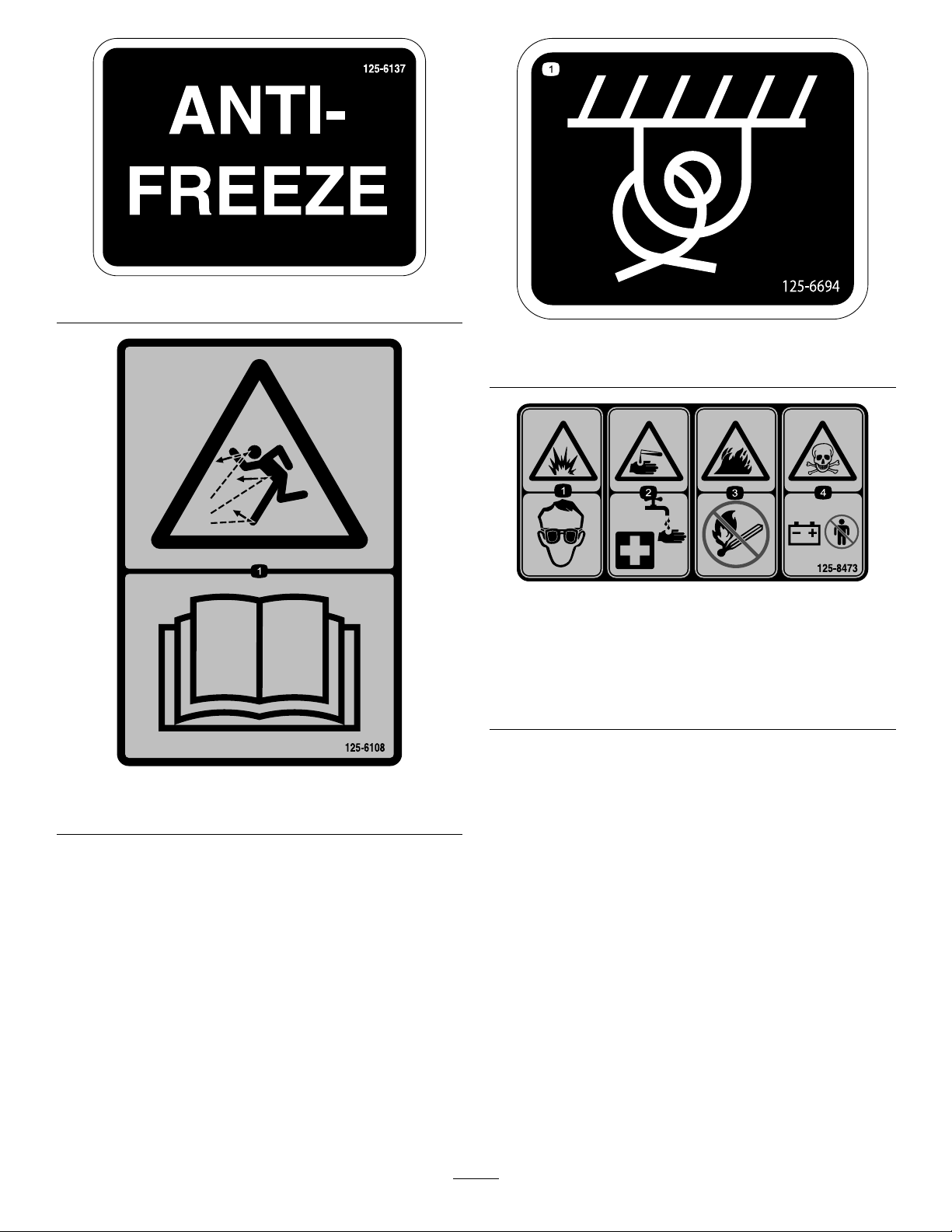
125-6137
125-6694
1.Tie-downpoint
125-8473
125-6108
1.Thrownobjecthazard—readtheOperator’sManual.
1.Explosionhazard—wear
eyeprotection.
2.Causticliquid/chemical
burnhazard—rinse
affectedareaandseek
medicalassistance.
3.Firehazard—keepopen
amesaway.
4.Poisonhazard—donot
tamperwiththebattery.
10
Page 11
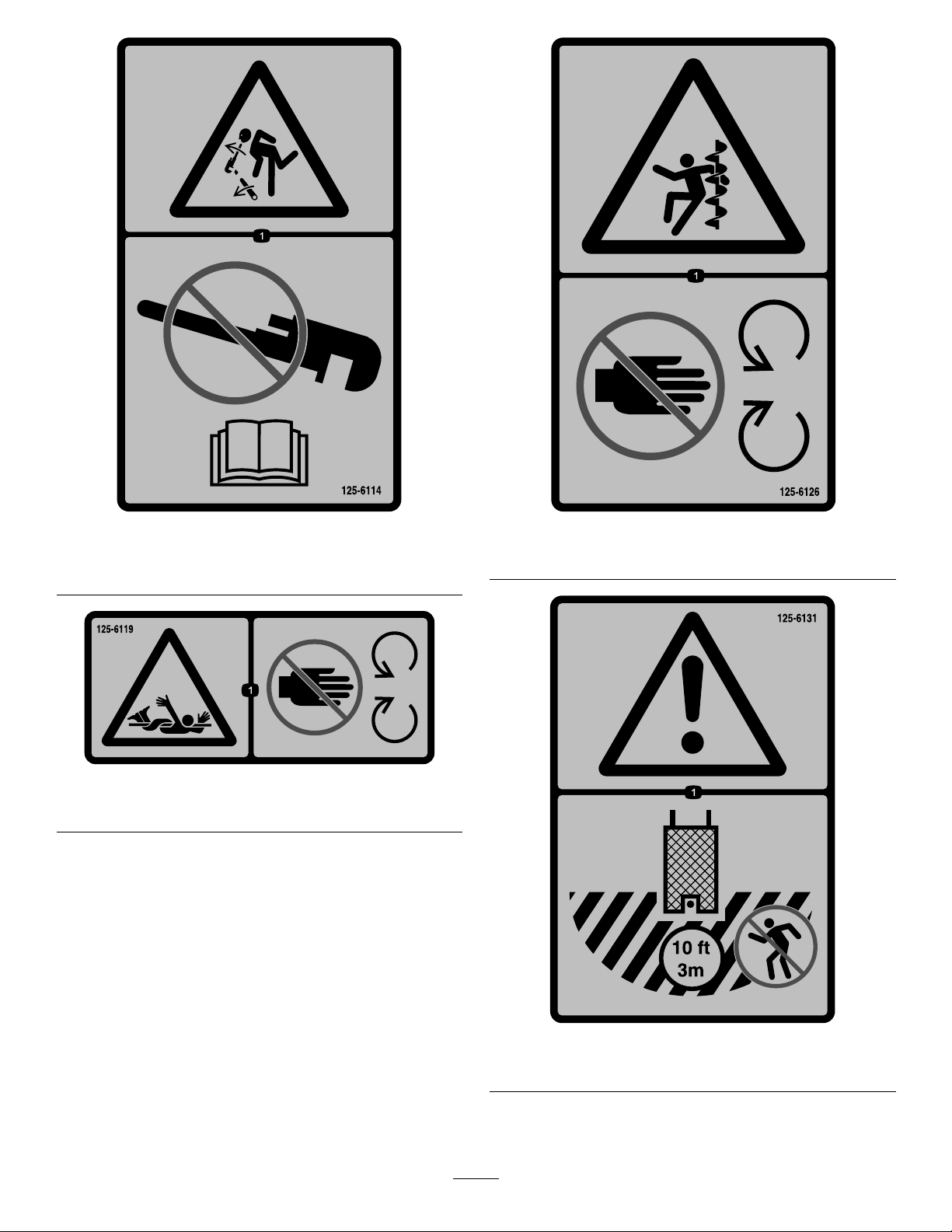
125-6114
125-6126
1.Storedenergyhazard—donotusetools;readthe
Operator’sManual.
125-6119
1.Entanglementhazard—keepawayfrommovingobjects.
1.Entanglementhazard—keepawayfrommovingparts.
125-6131
1.Warning—stayatleast3m(10ft)awayfromthemachine.
11
Page 12
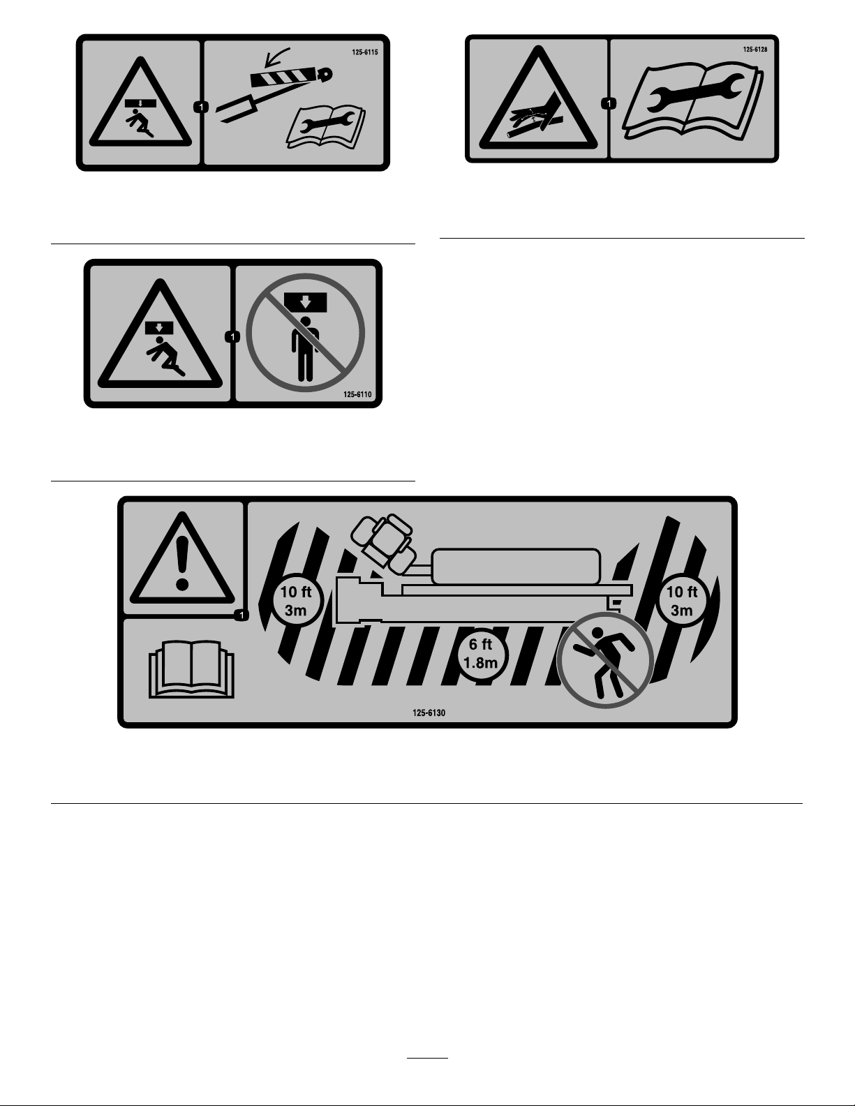
125-6115
1.Crushinghazard—deploycylinderlocksbeforeperforming
maintenance.
125-6110
1.Crushinghazard—donotstandunderanypartofthe
machine.
125-6128
1.Highpressureuidhazard,injectionintothebody—read
theOperator’sManualbeforeperformingmaintenance.
125-6130
1.Warning—readtheOperator’sManual;stayatleast3m(10ft)awayfromthefrontandrearofthemachineand1.8m(6ft)
awayfromthesidesofthemachine.
12
Page 13
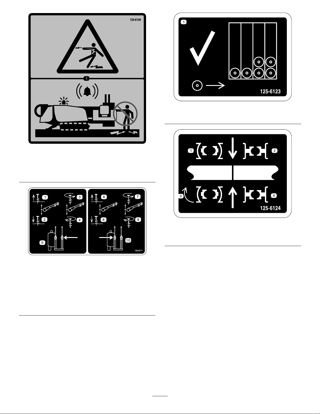
125-6109
1.Electricalshockhazard—whentheZap-Alertsystemis
activatedbyapowerstrike,donotleavetheoperator’s
positionortouchthegroundandthemachineatthesame
time;themachinewillbeenergizedwithelectricalpower .
125-6123
1.Loadpipesfrombackrowrst.
125-6124
1.Centerthepipejointbetweentheupper(makeup/breakout
wrench)andlowerwrenches(stationarywrench).
125-6111
1.Stakeup6.Stakeup
2.Stakedown7.Stakespin
3.Stakespin
counterclockwise
4.Stakespinclockwise9.Stakespinclockwise
5.Leftstake
counterclockwise
8.Stakedown
10.Rightstake
13
Page 14
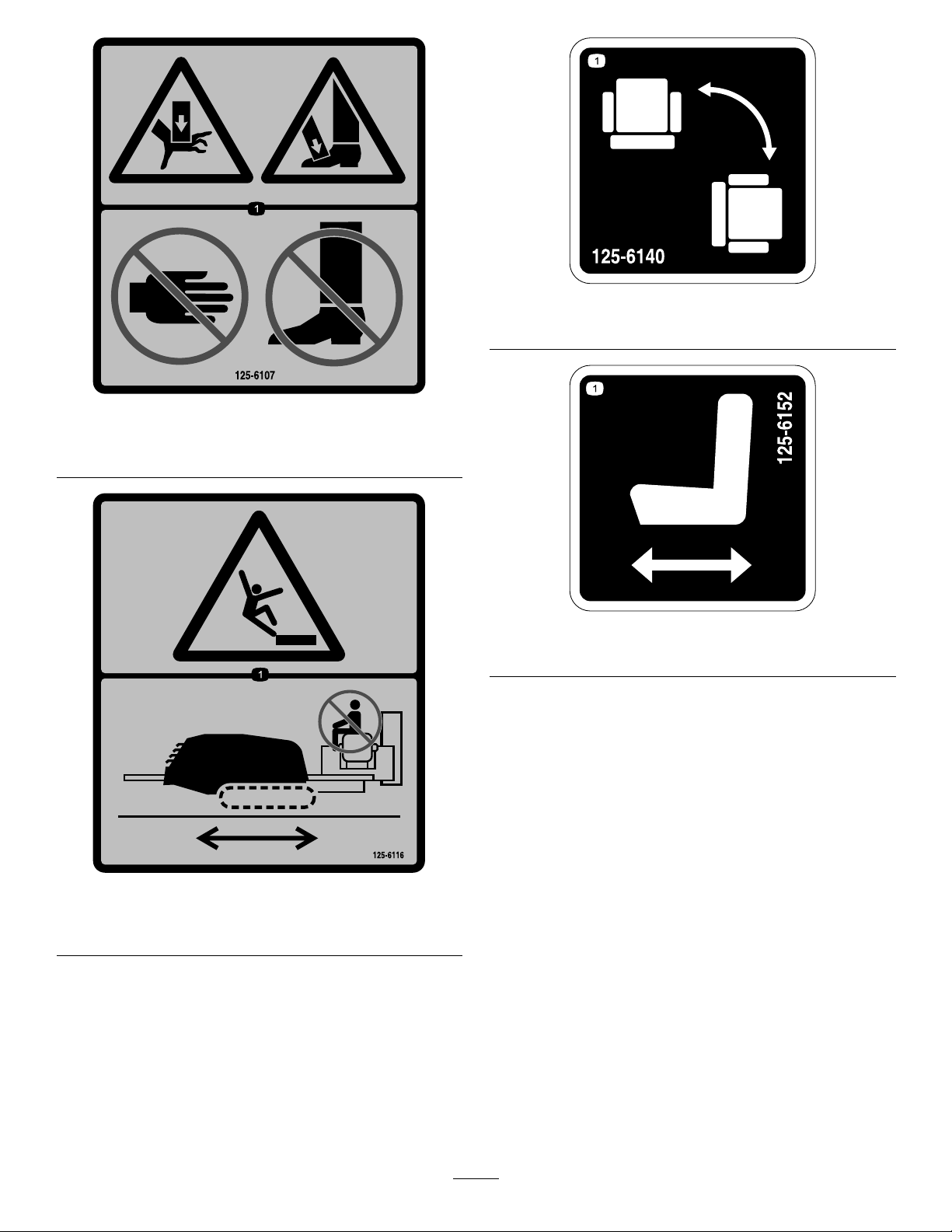
125-6107
1.Crushinghazardofhandandfoot—keephandsandfeet
away.
125-6140
1.Rotatethechair.
125-6152
1.Moveseatforwardsandbackwards.
125-6116
1.Fallinghazard—donotmovethemachinewhensomeone
isintheoperator’sposition.
14
Page 15
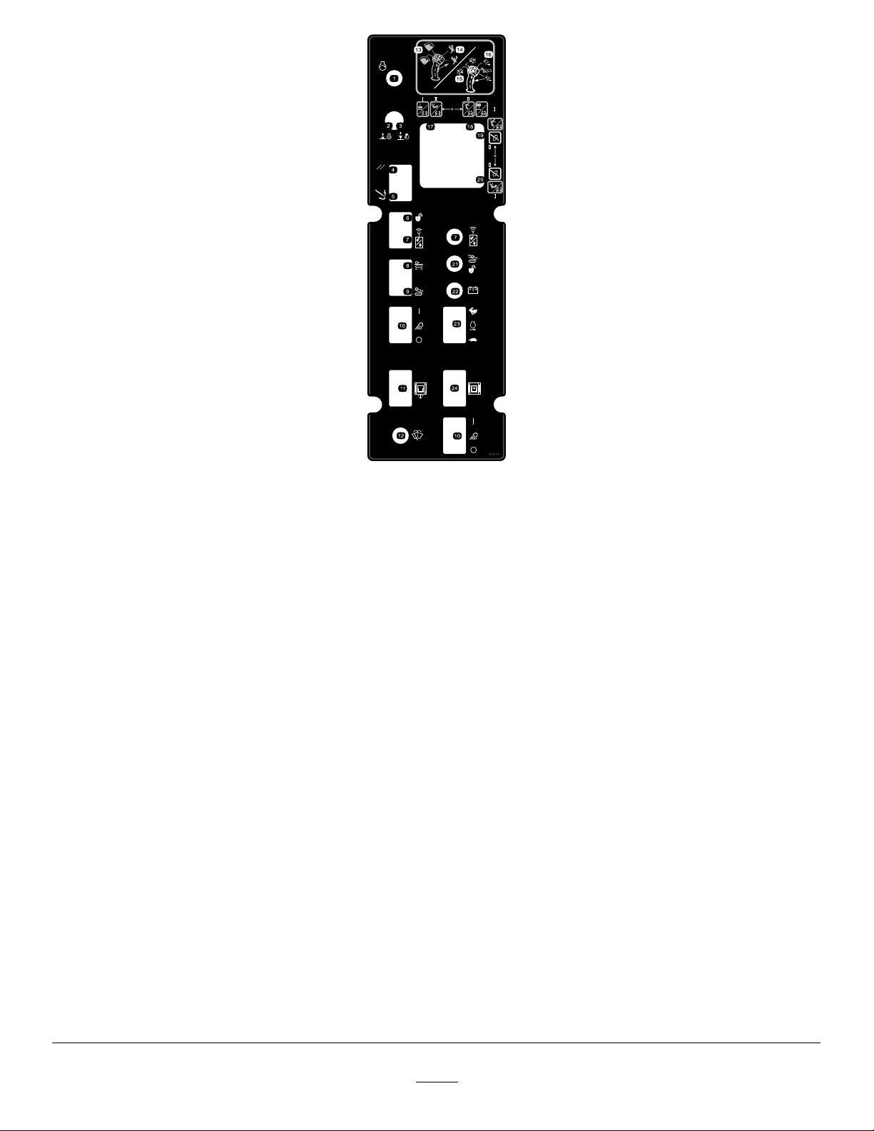
125-6158
ModelwithCabonly
1.Engine—start
2.Pressdowntostoptheengine14.Withtriggerreleased,upperbuttonclosespipegripper,lower
3.Pulluptostarttheengine
4.ResetZap-Alertsystem
5.Zap-Alertsystemtriggered
6.Unlockexit-sidelockout
7.Resetexit-sidelockout
8.Engagedrivemovementandsetupfunctions20.ModeI—lefttriggerreleased,raisespipeelevator;left
9.Engagedrillcarriagemovementandotherdrillfunctions
10.TurntheworklightOnorOff
11.Swingthecabinorout
12.Windshield-wipercontrol24.Rotatethecabclockwiseorcounterclockwise
13.Withtriggerreleased,rockforwardtorotatebaskettoward
pipecam,rockbackwardtorotatebaskettowarddrillframe.
buttonopenspipegripper.
15.Withtriggerpressed,rockforwardtorotatetheupperwrench
(makeup/breakoutwrench)counterclockwisetoloosenajoint;
rockrearwardtorotatetheupperwrench(makeup/breakout
wrench)clockwisetotightenajoint.
16.Withtriggerpressed,pressfrontorrearbuttontoresume
thepreviouslysetauto-drillspeed;pressandholdthefront
buttontoincreasetheauto-drillspeed;pressandholdthe
rearbuttontodecreasetheauto-drillspeed.
17.ModeI—lefttriggerreleased,extendspipegrippertowarddrill
frame;lefttriggerpressed,openslowerwrench(stationary
wrench).ModeII—spindrillspindleclockwise.
18.ModeI—lefttriggerreleased,extendspipegrippertowardpipe
holder;lefttriggerpressed,closeslowerwrench(stationary
wrench).ModeII—spindrillspindlecounterclockwise.
19.ModeI—lefttriggerreleased,lowerspipeelevator;left
triggerpressed,opensupperwrench(makeup/breakout
wrench).ModeII—lefttriggerreleased,extendspipegripper
towarddrillframe;lefttriggerpressed,opensupperwrench
(makeup/breakoutwrench).
triggerpressed,closesupperwrench(makeup/breakout
wrench).ModeII—lefttriggerreleased,extendspipegripper
towardpipeholder;lefttriggerpressed,closesupperwrench
(makeup/breakoutwrench).
21.Exit-sidelockout—drill-enabledlight
22.Transmitter-battery-statusLight
23.Increaseordecreasetheenginespeed
15
Page 16
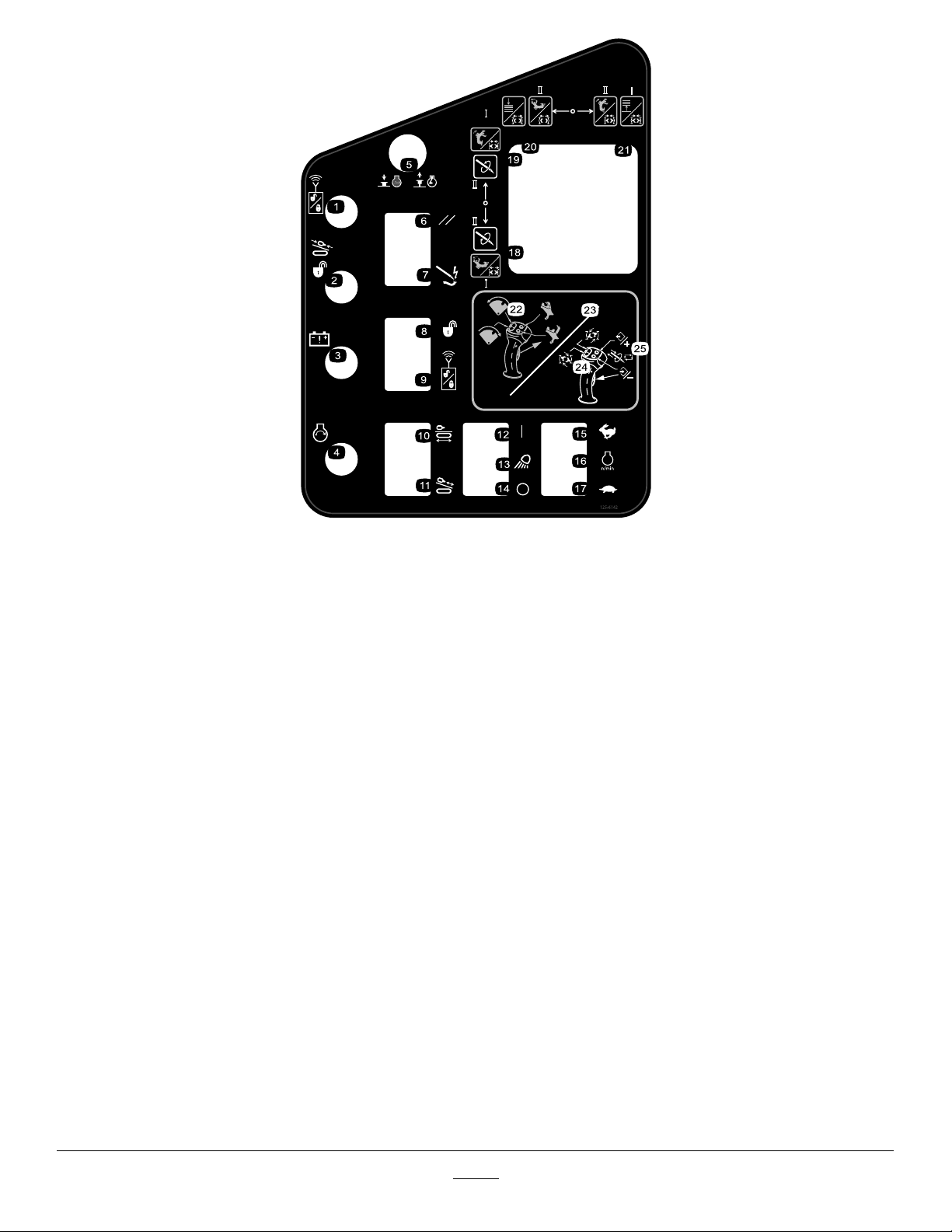
125-6142
1.Exit-sidelockout—resetlight
2.Exit-sidelockout—drill-enabledlight15.Pressandholdtoincreaseenginespeed.
3.Transmitter-battery-statuslight16.Enginespeed
4.Engine—start17.Pressandholdtodecreaseenginespeed.
5.Pressdowntostoptheengine;pulluptostarttheengine.
6.ResetZap-Alertsystem
7.Zap-Alertsystemtriggered
8.Unlockexit-sidelockout
9.Resetexit-sidelockout
10.Engagedrivemovementandsetupfunctions
11.Engagedrillcarriagemovementandotherdrillfunctions24.Withtriggerpressed,rockforwardtorotatetheupperwrench
12.Worklights—On25.Withtriggerpressed,pressfrontorrearbuttontoresume
13.Worklights
14.Worklights—Off
18.ModeI—lefttriggerreleased,extendspipegrippertowarddrill
frame;lefttriggerpressed,openslowerwrench(stationary
wrench).ModeII—spindrillspindleclockwise.
19.ModeI—lefttriggerreleased,extendspipegrippertowardpipe
holder;lefttriggerpressed,closeslowerwrench(stationary
wrench).ModeII—spindrillspindlecounterclockwise.
20.ModeI—lefttriggerreleased,lowerspipeelevator;left
triggerpressed,opensupperwrench(makeup/breakout
wrench).ModeII—lefttriggerreleased,extendspipegripper
towarddrillframe;lefttriggerpressed,opensupperwrench
(makeup/breakoutwrench).
21.ModeI—lefttriggerreleased,raisespipeelevator;left
triggerpressed,closesupperwrench(makeup/breakout
wrench).ModeII—lefttriggerreleased,extendspipegripper
towardpipeholder;lefttriggerpressed,closesupperwrench
(makeup/breakoutwrench).
22.Withtriggerreleased,rockforwardtorotatebaskettoward
pipecam,rockbackwardtorotatebaskettowarddrillframe.
23.Withtriggerreleased,upperbuttonclosespipegripper,lower
buttonopenspipegripper.
(makeup/breakoutwrench)counterclockwisetoloosenajoint;
rockrearwardtorotatetheupperwrench(makeup/breakout
wrench)clockwisetotightenajoint.
thepreviouslysetauto-drillspeed;pressandholdthefront
buttontoincreasetheauto-drillspeed;pressandholdthe
rearbuttontodecreasetheauto-drillspeed.
16
Page 17
125-1641
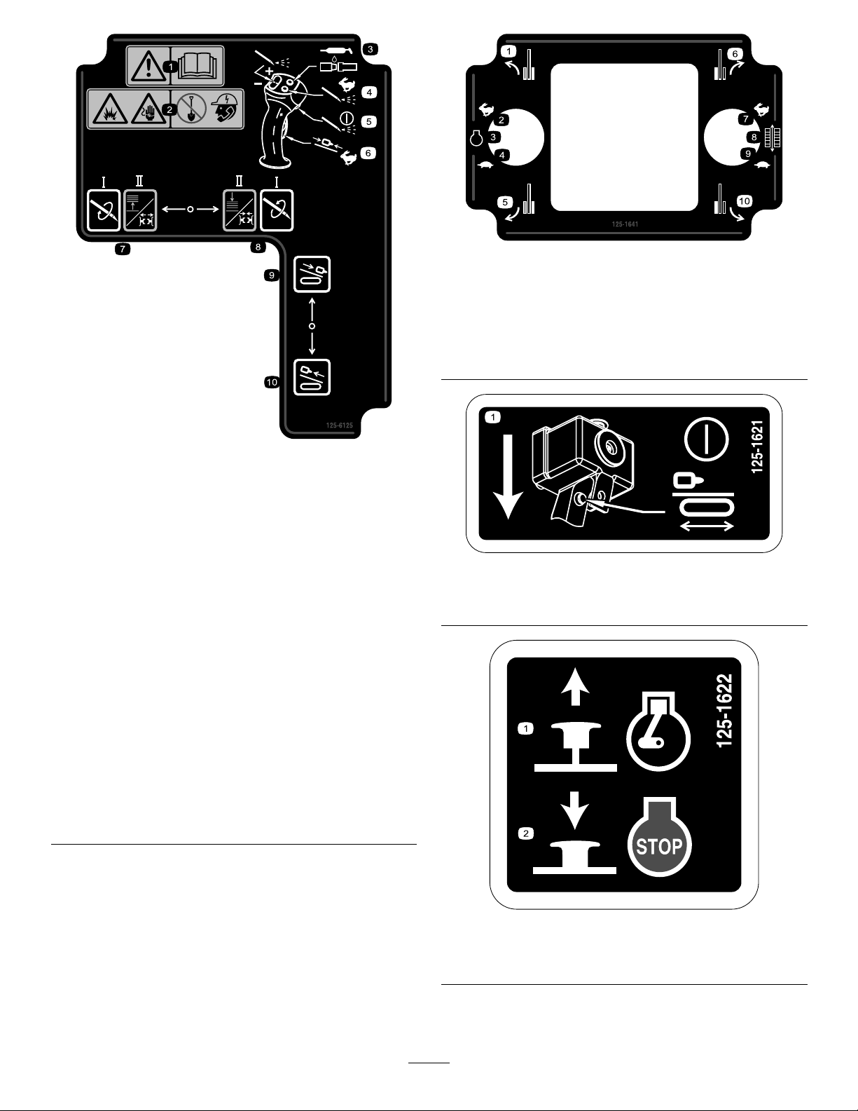
1.Warning—readthe
Operator’sManual.
2.Explosionhazard;
electricalshock
hazard—donotdigbefore
callinglocalservices.
3.Presstoapplythread-joint
compound.
4.Pressandholdfor
maximumdrillinguid
pressure;releasetostop
theow .
5.Presstoturnthe
drilling-uidpumpon
oroff.
125-6125
6.Pressandholdtomove
7.ModeI—spindrillspindle
8.ModeI—spindrillspindle
9.Thrustthedrillcarriage
10.Pullthedrillcarriage
thedrillcarriageathigh
speedupordownthedrill
frame.
clockwise.ModeII—left
triggerpressed,openthe
lowerwrench(stationary
wrench);lefttrigger
released,raisethepipe
elevator.
counterclockwise.Mode
II—lefttriggerpressed,
closethelowerwrench
(stationarywrench);left
triggerreleased,lowerthe
pipeelevator.
forward.
rearward.
1.Forwardleft
2.Increaserpm7.High
3.Enginespeed8.Trackspeed
4.Decreaserpm9.Low
5.Reverseleft
6.Forwardright
10.Reverseright
125-1621
1.Presstheoperatorpresenceswitchtoenablemachine
movement.
125-1622
1.Pulluptostarttheengine.2.Pushdowntostopthe
engine.
17
Page 18
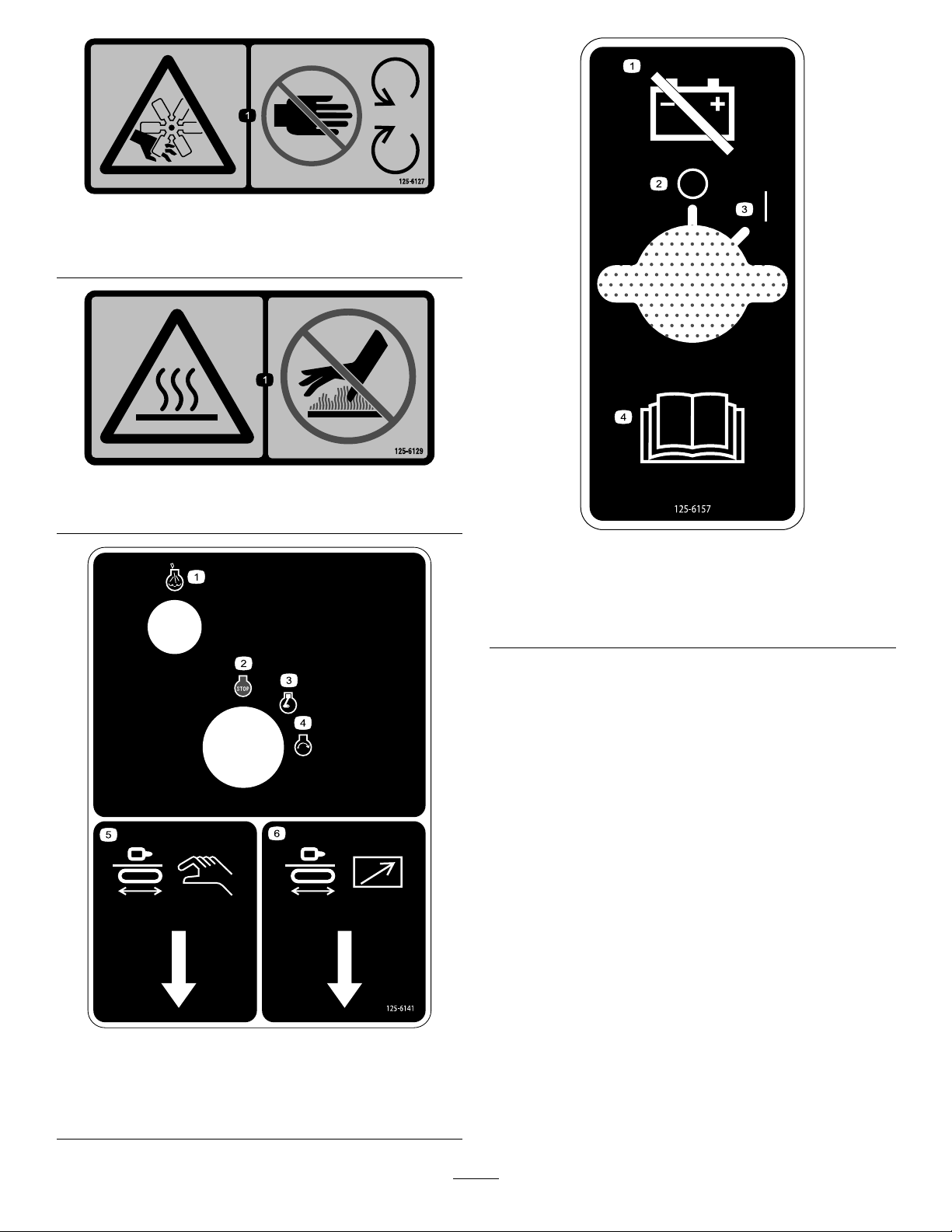
125-6127
0000
0000
0000
1.Cutting/dismembermenthazard,fan—keepawayfrom
movingparts.
125-6129
1.Hotsurface—keepawayfromhotsurfaces.
125-6157
1.Disconnectthebattery
3.On/Start
power.
2.Off/Stop4.ReadtheOperator’s
Manual.
125-6141
1.Engine—heatinglight4.Engine—start
2.Engine—stop5.Drill-pendantreceptacle
3.Engine—run6.Drive-pendantreceptacle
18
Page 19
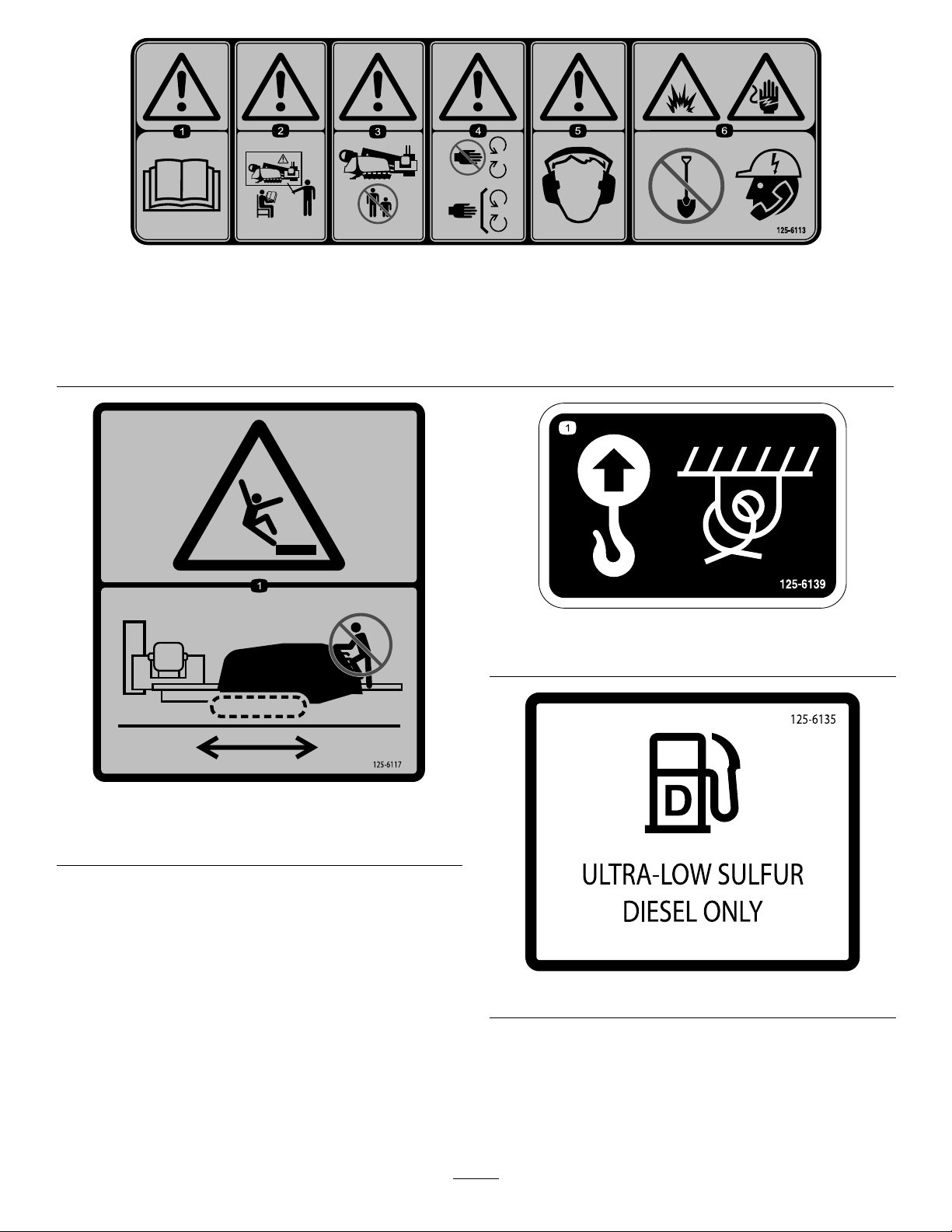
125-6113
1.Warning—readtheOperator’sManual.4.Warning—keepawayfrommovingparts;keepallguardsand
2.Warning—donotoperatethemachineunlessyouaretrained.5.Warning—wearhearingprotection.
3.Warning—keepbystandersawayfromthemachine.6.Explosionhazard,electricalshockhazard;donotdigbefore
shieldsinplace.
callinglocalutilities.
125-6139
1.Liftpointandtie-downpoint
125-6117
1.Fallinghazard—donotstandonthemachinewhileitis
moving.
125-6135
19
Page 20
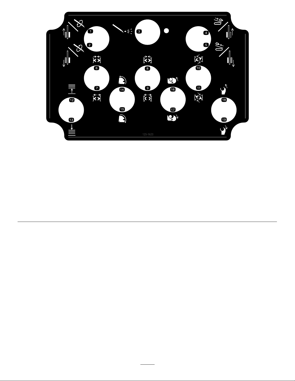
125-1623
1.Forwardlefttrack/forwardrotary11.Wrenchmakeup(forupperwrench)
2.Reverselefttrack/reverserotary
3.Drillinguidpumpon
4.Forwardrighttrack/forwardcarriage
5.Reverserighttrack/reversecarriage15.Forward(towardoperator)camrotation
6.Tightenlowerwrench(stationarywrench)
7.Loosenlowerwrench(stationarywrench)
8.Tightenupperwrench(makeup/breakoutwrench)
9.Loosenupperwrench
10.Wrenchbreakout(forupperwrench)
12.Raisepipeelevator
13.Lowerpipeelevator
14.Reversecamrotation
16.Tightenpipegrip
17.Loosenpipegrip
18.Reversedrillspindle
19.Forward(towardoperator)drillspindle
20
Page 21
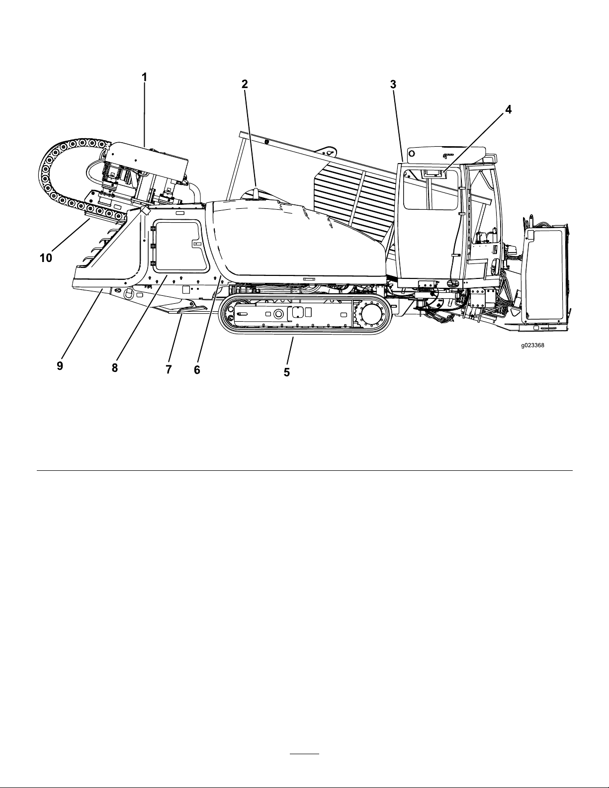
ProductOverview
Figure5
1.Drillcarriage6.Fronthood
2.Zap-alertstrobe7.Rightstabilizer
3.Cab
4.Monitor9.Rearhood
5.Track
8.Rear-accessdoor
10.Thrustframe
21
Page 22
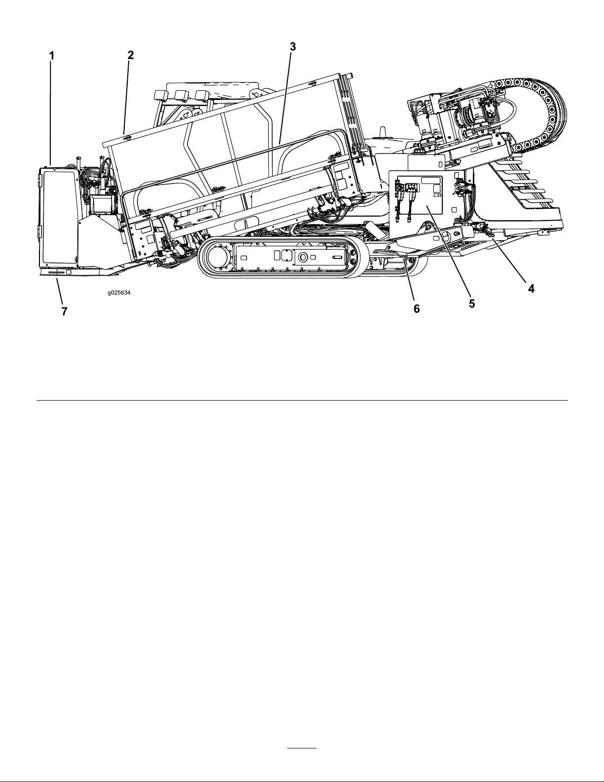
Figure6
1.Stake-downcage
2.Pipeholder
3.Pedestriansafetybar7.Stake-downplate
4.Drilling-uid-pumpinlet
5.Rear-controlpanel
6.Leftstabilizer
22
Page 23
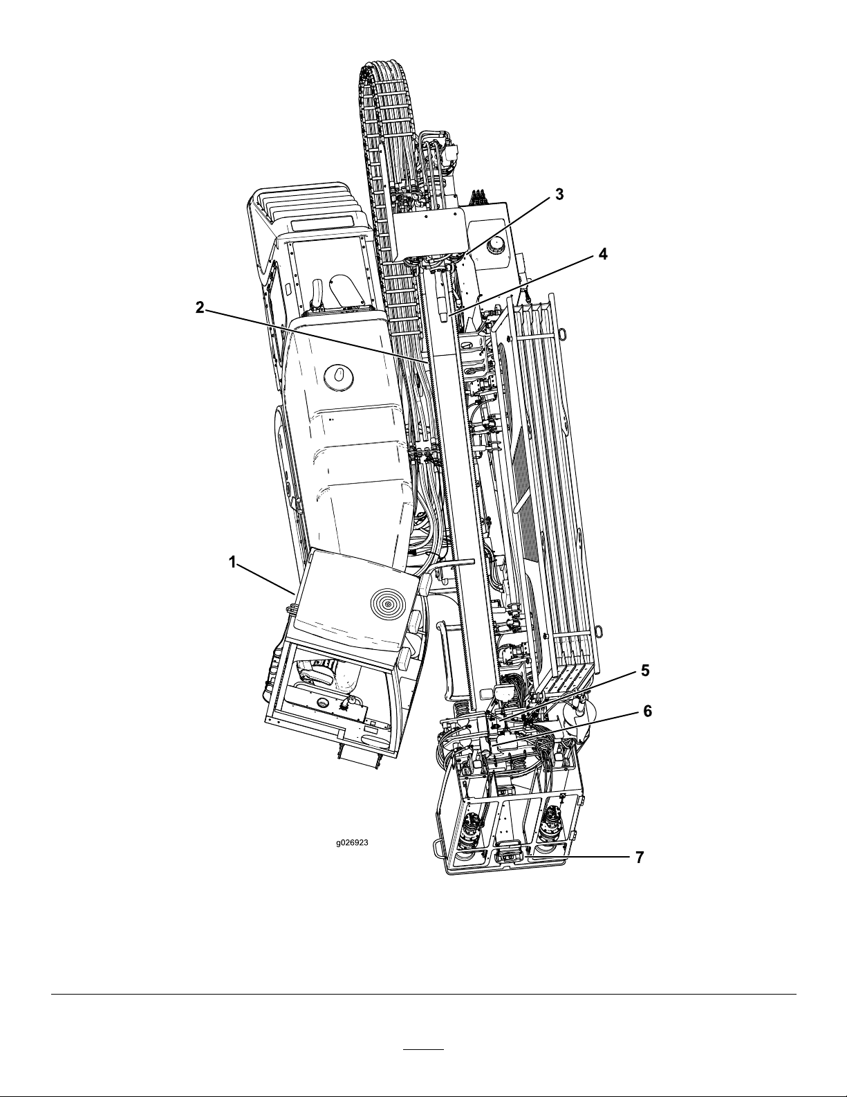
Figure7
1.Cab5.Upperwrench(makeup/breakoutwrench)
2.Thrustframe6.Lowerwrench(stationarywrench)
3.Drillcarriage7.Pipewiper
4.Drillspindle
23
Page 24
Controls
Refertothefollowingsectionsfortheappropriatemachine
controls:
•OperatorPlatform
•Monitor
•ControlPanel
•LeftJoystick—ModeI
•LeftJoystick—ModeII
•RightJoystick—ModeI
•RightJoystick—ModeII
•Exit-Side-LockoutSystem
•RearControlPanel
•DrillFrameandStabilizerControls
•DrivePendant
•DrillPendant
•Stake-DownLevers
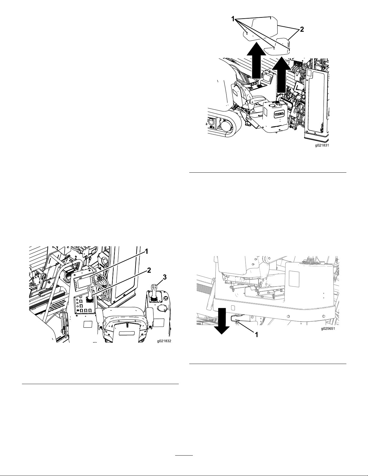
Figure9
1.Screws2.Covers
•Battery-DisconnectSwitch
OperatorPlatform
Theoperatorplatform,locatedontheright,frontcornerof
themachine,containsmostofthecontrolsthatyouuseto
operatethedrillingfunctionsofthemachine.
Figure8
1.Operatordisplay
2.Leftcontrolpaneland
joystick
3.Rightjoystick
Operator-platformLatch
Theoperatorplatformswingsoutawayfromthemachine,
makingroomforyoutosit.Ithas4positions:travel(swung
allthewayintothemachine),full-out,and2intermediate
positions.ReturntheplatformtotheTravelpositionbefore
movingthemachine.
Toreleasetheplatformandswingitoutorin,pressdownon
therearplatformlatch(Figure10).
Figure10
1.Rearplatformlatch
Toreleasetheplatformandswingitoutorin,pressuponthe
frontplatformlatch(Figure11).
Operator-controlsCovers
Thecoversprotecttheoperatorcontrolsfromadverse
weatherconditions,suchasrain,wind,sunlight,etc.Remove
thembeforeusingthemachineandreplacethembefore
leavingthemachinefortheday.Eachcoverissecuredwith2
screwsasshowninFigure9.
24
Page 25
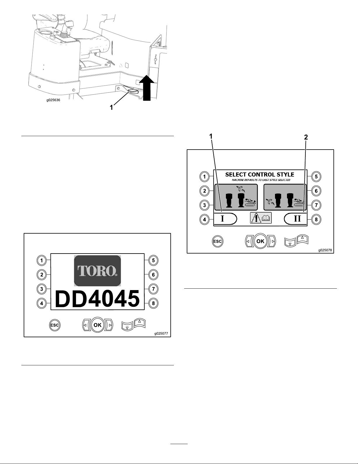
Figure11
1
2
3
4
5
6
7
8
OK
ESC
4045
g025077
1
2
3
4
5
6
7
8
OK
ESC
1
2
g025078
Control-selectScreen
Whenyoupowerupthemachine,thisisthescreenthat
appearsafterthestart-upscreen.
The2controllayoutsthattheoperatorcanchoosefrom
consistofthefollowing:
•ModeI—Thisfunctionplacesthedrillingfunctionson
therightjoystick,whiletheleftjoystickoperatesthepipe
loaderandthewrenchfunctions(Figure13).
Pressbuttonnumber4toselectthisfunction(Figure13).
•ModeII—Thisfunctionsplitsthedrilling,wrench,and
pipeloadingbetweentheleftandrightjoysticks(Figure
13)
1.Frontplatformlatch
Monitor
Start-upScreen
Whenyoupowerupthemachine,thisistherstscreenthat
appears(Figure12).
Thestart-upscreenappearswheneveryoupresstheESC
button(foundinthebottom-leftcornerofthescreen)from
therst3pagesofthedisplay.
Note:Nokeysareactivefromthisscreen.
Pressbuttonnumber8toselectthisfunction(Figure13).
Figure13
Control-selectScreen
1.ModeI2.ModeII
Note:Ifaselectionisnotmadewithin5seconds,the
screenwilldefaulttotheprevioussettingandwillgotothe
Machine-informationScreen(page26).
Start-upScreen
Figure12
25
Page 26
Machine-informationScreen
2
3
4
5
6
7
8
OK
ESC
1
2
g025079
3
4
5
5
2
3
4
5
6
7
8
OK
ESC
1
2
g025080
3
4
6
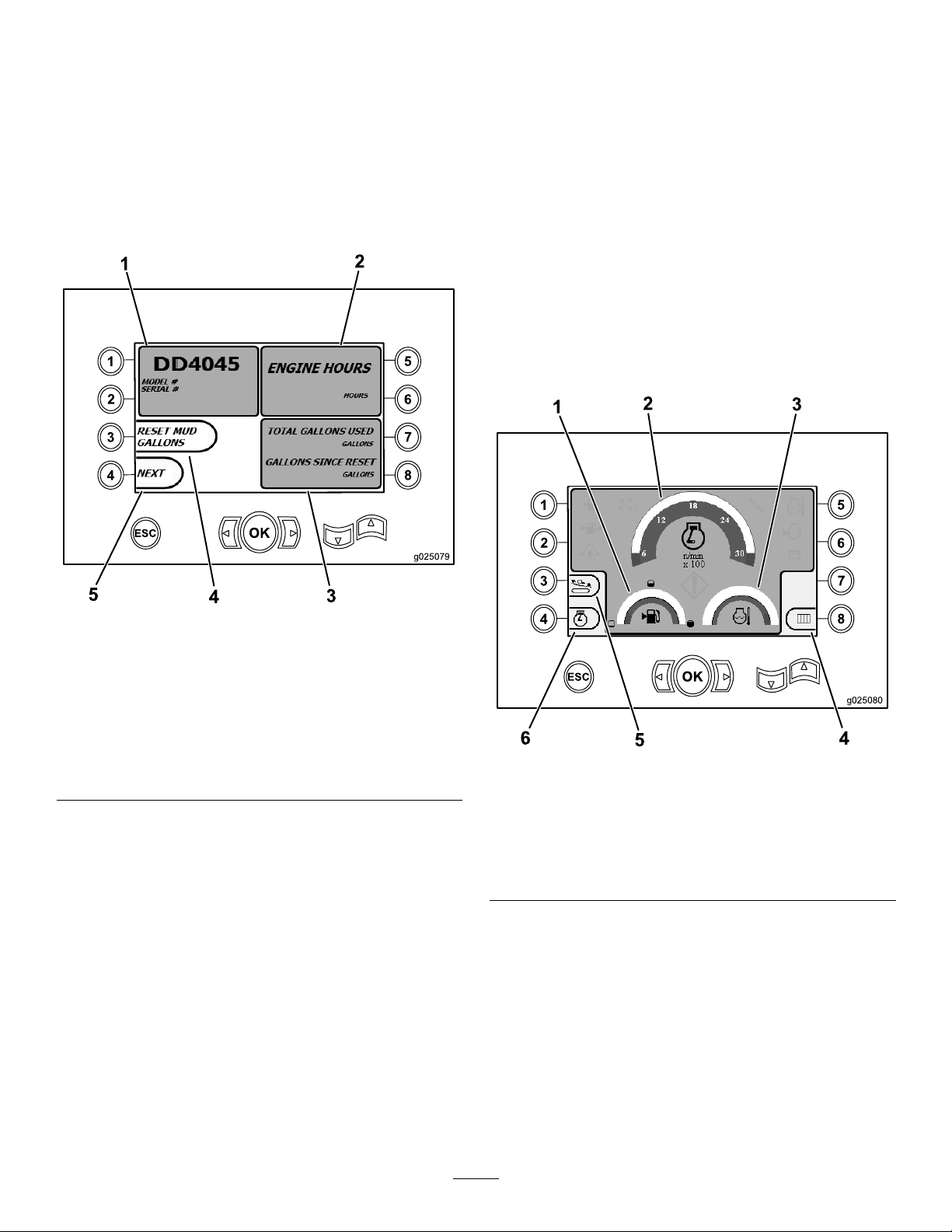
MainOperatingScreen
Thisscreencontainsthefollowinginformation:
•Themachinemodelandserialnumber(Figure14).
•Thenumberofenginehoursforthemachine(Figure14).
•Thenumberofdrillinguid-gallonsusedandthenumber
ofre-settabledrilling-uidgallonsused(Figure14).
Note:Pressbutton3toresetthenumberofdrilling-uid
gallonssincethelastreset(Figure14).
Toaccessthisscreen,pressbutton4orthedownarrowon
theMachine-informationScreen(page26).
Themainoperatingscreendisplaystheengine-speed(rpm)
gauge,thefuel-quantitygauge,theengine-temperaturegauge,
therod-rowselector,thrustcontrol,andhorsepowercontrol
(Figure15).
Thelow-fuelindicatorlightsuponthemain-operatingscreen
whenthemachineisrunninglowonfuel(Figure15).
Pressbuttonnumber3toselectthethrustcontrol(Figure15).
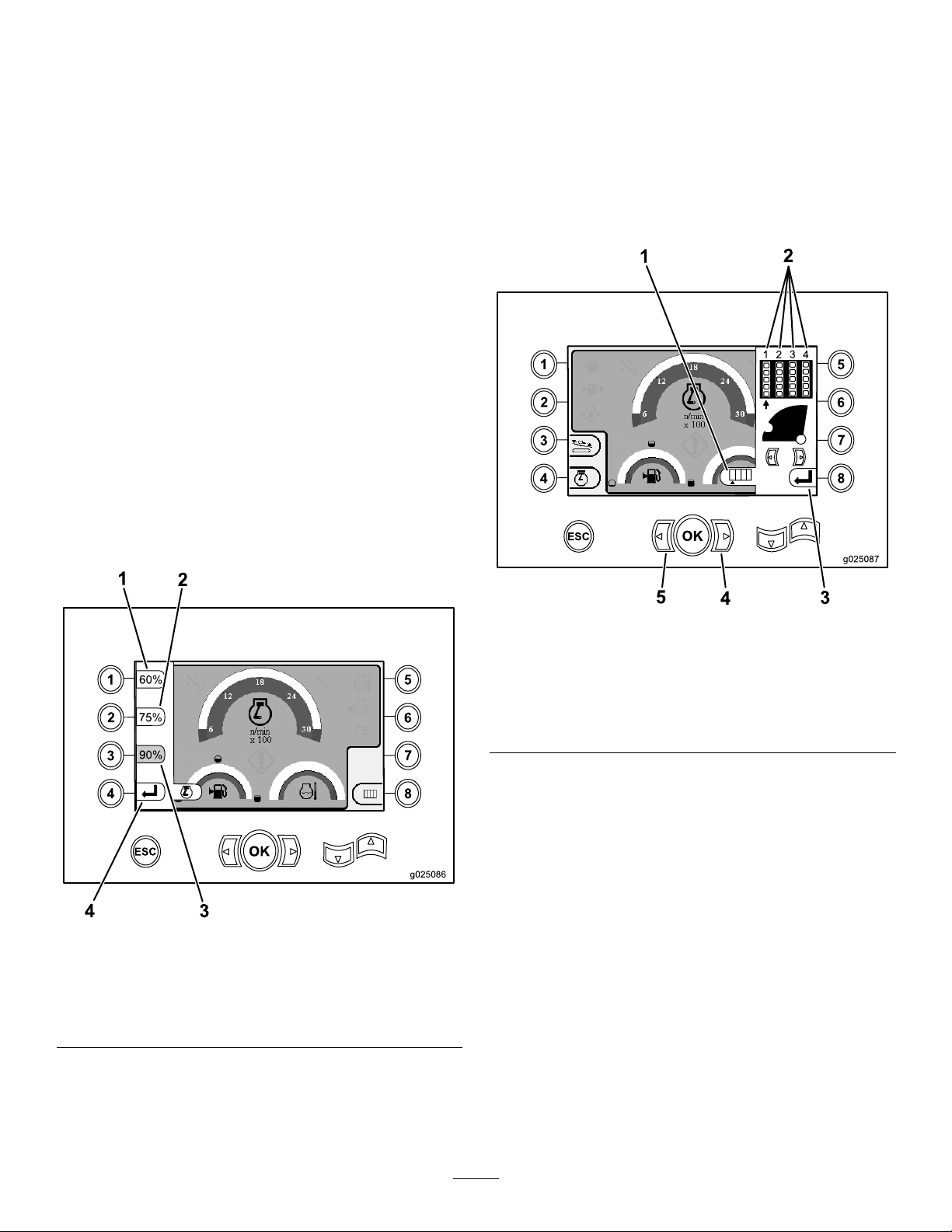
Pressbuttonnumber4toselectthehorsepowercontrol
(Figure15).
Pressbuttonnumber8fortherod-rowselector(Figure15).
1.Modelandmachineserial
number
2.Numberofenginehours
3.Totalnumberof
drilling-uidgallonsused
andresettabledrilling-uid
gallonsused
Machine-informationScreen
Figure14
4.Resetdrilling-uidgallons
5.Nextscreen
Figure15
MainOperatingScreen
1.Fuelgauge4.Rod-rowselector
2.Engine-speed(rpm)gauge
3.Coolant-temperature
gauge
5.Thrustcontrol
6.Horsepowercontrol
26
Page 27
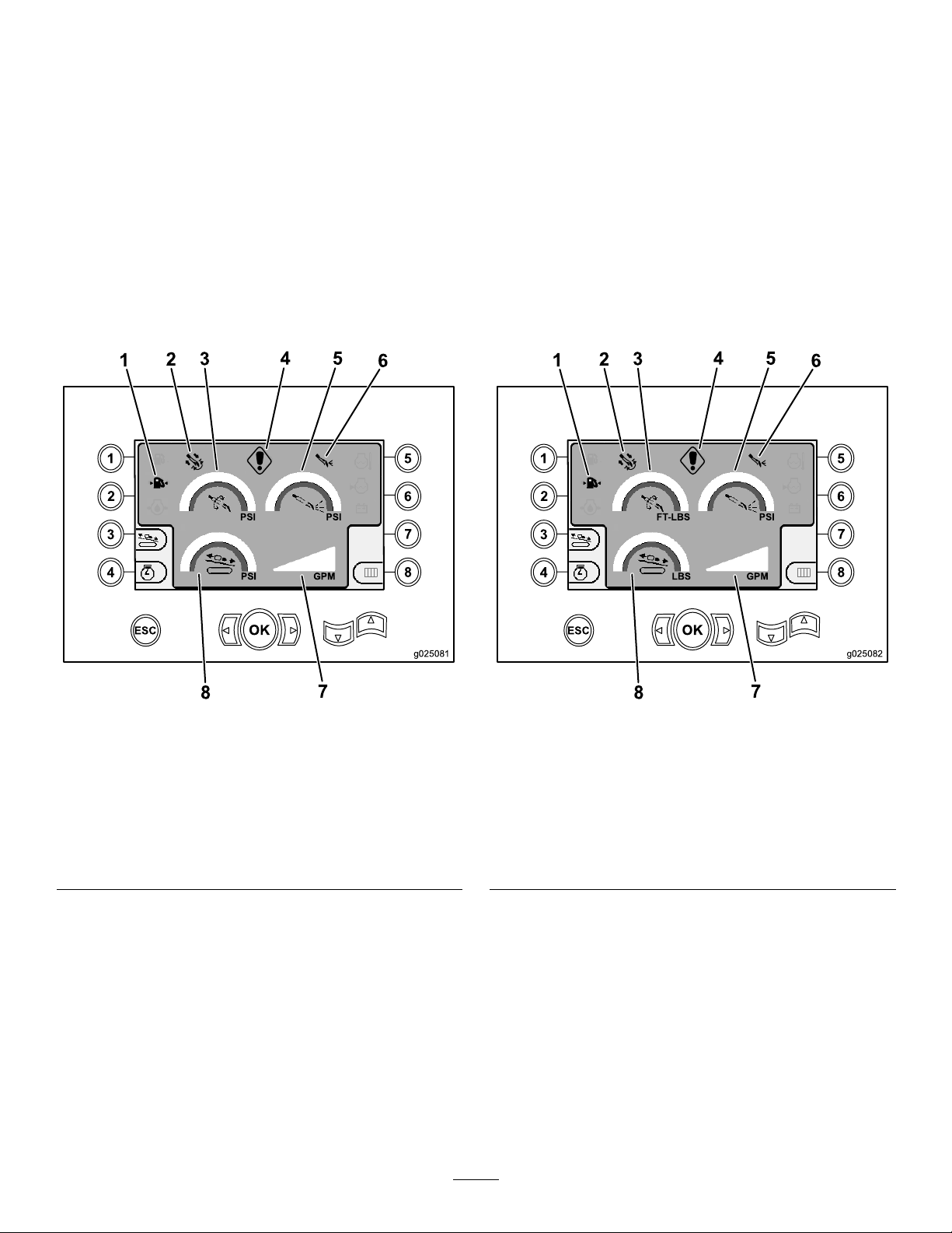
MainDrillFunctionsDisplayedinPressureScreen
2
3
4
5
6
7
8
OK
ESC
1
2
g025081
3
PSI PSI
PSI GPM
4
5
6
7
8
2
3
4
5
6
7
8
OK
ESC
1
2
g025082
3
FT-LBS PSI
LBS GPM
4
5
6
7
8
MainDrillFunctionsDisplayedinTorqueScreen
Toaccessthisscreen,pressthedown-arrowbuttononthe
MainDrillFunctionsDisplayedinPressureScreen(page27).
Thisscreenprovidesmeasurementsonrotarypressureinpsi,
drilling-uidpressureinpsi,carriagepressureinpsi,and
drilling-uidowrateingpm(Figure16).
Therearealso4indicators(listedfromtoptobottominthe
middleofthescreen),whichindicatethefollowing:
•Drillingand/orengine-errorcodewarning(Figure16)
•Low-fuelwarning(Figure16)
•DrillinguidisintheOnposition(Figure16)
•AutodrillingisintheOnposition(Figure16)
Toaccessthisscreen,pressthedownarrowontheMainDrill
FunctionsDisplayedinPressureScreen(page27).
Thisscreenprovidesmeasurementsonrotarytorquein
ft-lbs,drilling-uidpressureinpsi,carriageforceinlbs,and
drilling-uidowrateingpm(Figure17).
Therearealso4indicators(listedfromtoptobottominthe
middleofthescreen),whichindicatethefollowing:
•Drillingand/orengine-errorcodewarning(Figure17)
•Low-fuelwarning(Figure17)
•DrillinguidisintheOnposition(Figure17)
•AutodrillingisintheOnposition(Figure17)
Figure16
MainDrillFunctionsDisplayedinPressureScreen
1.Low-fuelindicator5.Drilling-uidpressure(psi)
2.Auto-drillingindicator
3.Rotarypressure(psi)7.Drilling-uidowrate
4.Drilling-faultindicator8.Carriage-pressuregauge
6.Drilling-uidindicator
(gpm)
(psi)
Figure17
MainDrillFunctionsDisplayedinTorqueScreen
1.Low-fuelindicator5.Drilling-uidpressure(psi)
2.Auto-drillingindicator
3.Rotarypressure(ft-lbs)7.Drilling-uidowrate
4.Drilling-faultindicator8.Carriage-pressuregauge
27
6.Drilling-uidindicator
(gpm)
(lbs)
Page 28
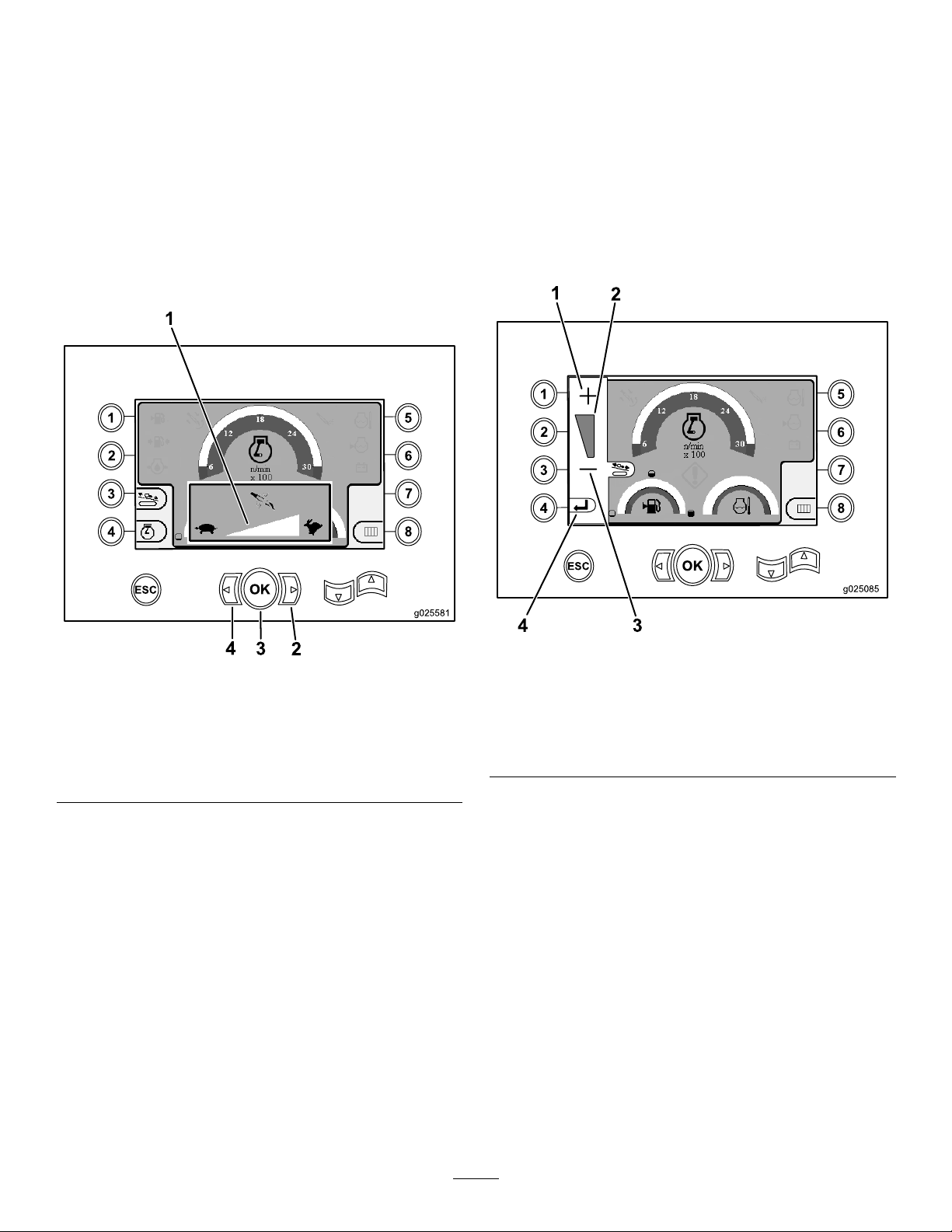
Drill-rotation-speedScreen
2
3
4
5
6
7
8
OK
1
g025581
ESC
2
3
4
1
2
3
4
5
6
7
8
OK
ESC
g025085
1
2
3
4
Thrust-controlScreen
Toaccessthisscreen,presstheOKbuttonontheMain
OperatingScreen(page26).
Thisscreenallowstheusertoincreaseordecreasethe
rotationspeedofthedrill.
Tochangetherotationspeedofthedrill,performthe
following:
1.PresstheLeftarrowtodecreasethespeed,orpressthe
Rightarrowtoincreasethespeed(Figure18).
2.PresstheOKbuttontosetthedrill-rotationspeed
(Figure18).
Thisscreenallowstheusertoincreaseordecreasethethrust
outputofthemachine.
Toaccessthisscreen,pressbuttonnumber3ontheMain
OperatingScreen(page26).
Tochangethethrustoutputofthemachine,performthe
following:
1.Pressbuttonnumber1toincreasethetorqueoutput,
orbuttonnumber3todecreasethetorqueoutputof
themachine(Figure19).
1.Drill-rotationspeedmeter
2.Rightarrow(increase
speed)
Figure18
Drill-rotation-speedScreen
3.OKbutton(setsthe
drill-rotationspeed)
4.Leftarrow(decrease
speed)
Figure19
Thrust-controlScreen
1.Increasethetorqueoutput3.Decreasethetorque
output
2.Torque-outputmeter4.Returntotheprevious
screen
2.Aftersettingthetorqueoutput,pressbuttonnumber
4(Figure19),andreturntotheMainOperating
Screen(page26).
28
Page 29
Horsepower-controlScreen
1
2
3
4
5
6
7
8
OK
ESC
g025086
1
2
3
4
1
2
3
4
1
2
3
4
5
6
7
8
OK
ESC
g025087
1
3
4
5
2
Pipe-row-selectorScreen
Toaccessthisscreen,pressbuttonnumber4ontheMain
OperatingScreen(page26).
Thehorsepowercontrolallowstheusertochangethe
speedsettingthattheenginecandrooptobeforethe
horsepower-controlsystemcanactivate.
Thehorsepowercontrolallowstheoperatortofunctionthe
unitatlowspeedlevels,sothattheenginecanstallunder
heavyloads.
Note:Forexample,atthe60%engine-speed(rpm)setting,
theenginecanstallunderheavyloads.
Afterpressingbuttonnumber4ataccessthehorsepower
control(Figure15),selectoneofthefollowingoptions:
•Pressbuttonnumber1toactivate60%enginespeed
(rpm)asshowninFigure20.
•Pressbuttonnumber2toactivate75%enginespeed
(rpm)asshowninFigure20.
•Pressbuttonnumber3toactivate90%enginespeed
(rpm)asshowninFigure20.
•Pressbuttonnumber4toreturntothemain-operating
screen(Figure20).
Thisscreenallowsyoutoselecttherowofpipe(s)thatyou
wanttouse.
Toaccessthisscreen,pressbuttonnumber8ontheMain
OperatingScreen(page26).
Toselectyourpiperow ,performthefollowing:
1.Presstherightorleftarrowtoselecttherownumber
totherowyouwanttoaccess(Figure21).
Figure20
Horsepower-controlScreen
1.60%enginespeed(rpm)3.90%enginespeed(rpm)
2.75%enginespeed(rpm)
4.Returntotheprevious
screen
Figure21
Pipe-row-selectorScreen
1.Rowselector4.Rightarrow
2.Rownumber
3.Returntotheprevious
screen
5.Leftarrow
2.Afterplacingthearrowbeneaththerownumberyou
wanttoaccess,presstheOKbutton(Figure21),and
returntotheMainOperatingScreen(page26).
29
Page 30
Main-selectionScreen
2
3
4
5
6
7
8
OK
ESC
g025088
1
2
3
4
5
6
78
9
LubricationandMaintenanceScreens
Toaccessthisscreen,pressthedownarrowonthe
Main-selectionScreen(page30).
Thisscreenallowstheusertochoosefromthefollowing
options:
•Button1—ReturntotheMainOperatingScreen(page
26)asshowninFigure22
•Button2—Lubricationandmaintenancechart(Figure22)
•Button3—Readerrorcodes(Figure22)
•Button4—ReturntotheMainOperatingScreen(page
26)asshowninFigure22
•Button5—Diagnoseandadjustparameters(Figure22)
•Button6—Adjusttheloadercalibration(Figure22)
•Button7—Clearaservicereminder(Figure22)
•Button8—Air-hammercontrol(Figure22)
•OKbutton—ReturntotheMainDrillFunctions
DisplayedinPressureScreen(page27)asshownin
Figure22
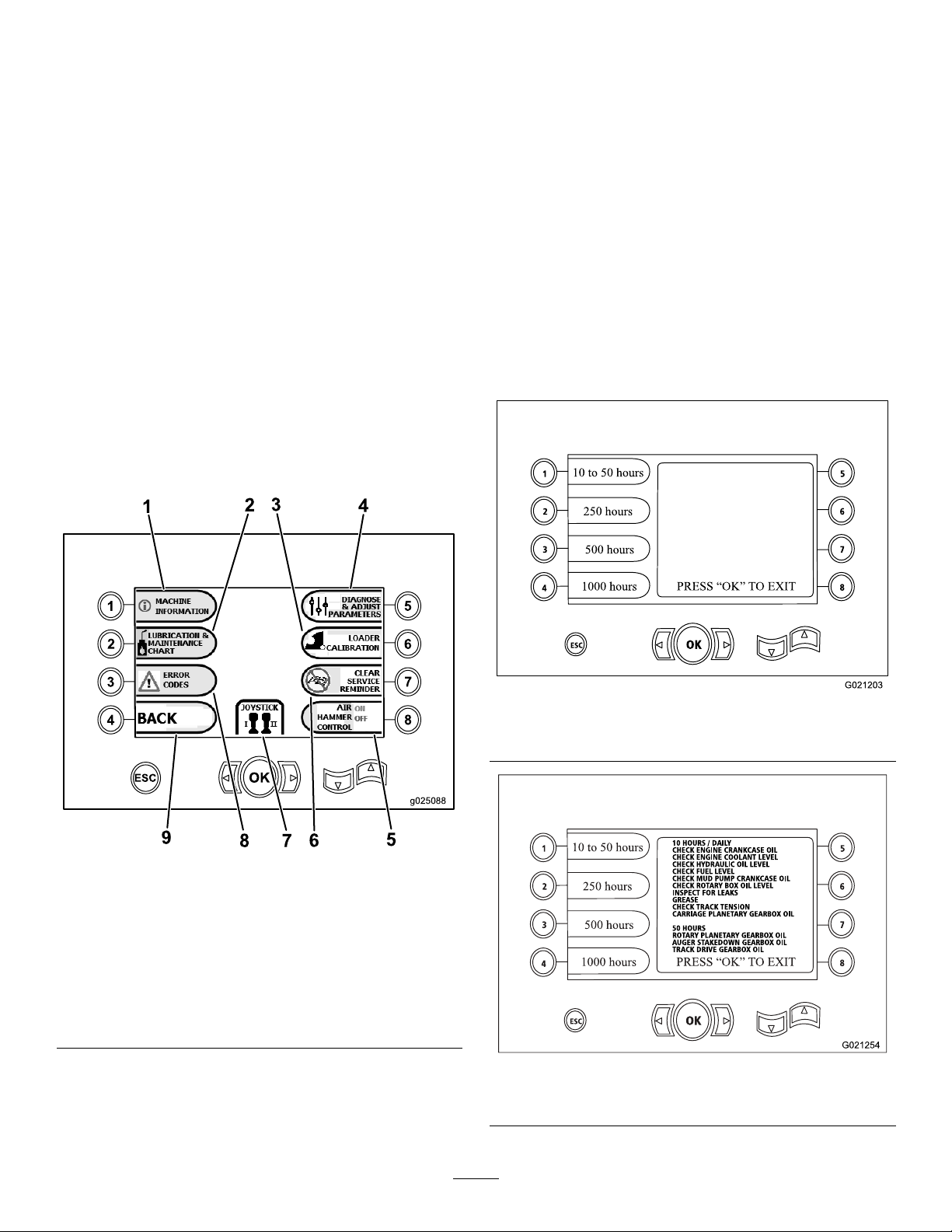
Toaccessthisscreen,pressbuttonnumber2ontheMain
OperatingScreen(page26).
Thesescreensprovidetheuserwithmaintenanceschedules
at10-hour,50-hour,250-hour,500-hour,and1,000-hour
increments.
Note:PresstheOKbuttontoexitthisscreen.
Pressthefollowingbuttonstoattainthesubsequent
maintenanceschedule:
•Button1—10-hourand50-hourmaintenanceschedule
(Figure24)
•Button2—250-hourmaintenanceschedule(Figure25)
•Button3—500-hourmaintenanceschedule(Figure26)
•Button4—1,000-hourmaintenanceschedule(Figure27)
Figure22
Main-selectionScreen
1.Machineinformation6.Clearservicereminder
2.Lubricationand
maintenancechart
3.Loadercalibration8.Errorcodes
4.Diagnoseandadjust
parameters
5.Air-hammercontrol
7.Control/joystickselection
9.ReturntotheMain
OperatingScreen
Figure23
MainMaintenanceScreen
10-Hourand50-HourMaintenanceScreen
Figure24
30
Page 31

Figure25
1
2
3
4
5
6
7
8
OK
ESC
1
2
3
4
5
250-HourMaintenanceScreen
ErrorCodesScreen
Toaccessthisscreen,pressbuttonnumber3ontheMain
OperatingScreen(page26).
Thisscreendisplaysthenumberofdrillerrorsandengine
errorsthathaveoccurred.
Ifmorethan1drillorengineerrorisshownonthescreen,
pressbutton5toseethenextdrillingerror,button7tosee
thenextengineerror,orbutton8toseethepreviousengine
error(Figure28).
Note:Iftherearenodrillingerrorsorengineerrors,press
theOKbuttontoexitthisscreen(Figure28).
Figure28
ErrorCodesScreen
Figure26
500-HourMaintenanceScreen
1.Totalnumberofdrillerrors
2.Nextengineerror
3.Nextdrillerror
DiagnoseandAdjustParametersScreen
4.Previousengineerror
5.Totalnumberofengine
errors
Toaccessthisscreen,pressbuttonnumber5ontheMain
OperatingScreen(page26).
ContactyourAuthorizedToroServiceDealertodiagnose
andadjustparameters.
Note:T oaccesstheDiagnoseandAdjustParametersScreen,
1000-HourMaintenanceScreen
Figure27
youarerequiredtohavetheaccessPINforthemachine.
31
Page 32
Loader-calibrationScreen
1
2
3
4
5
6
7
8
OK
ESC
1
2
3
Loader-cam-calibrationScreen
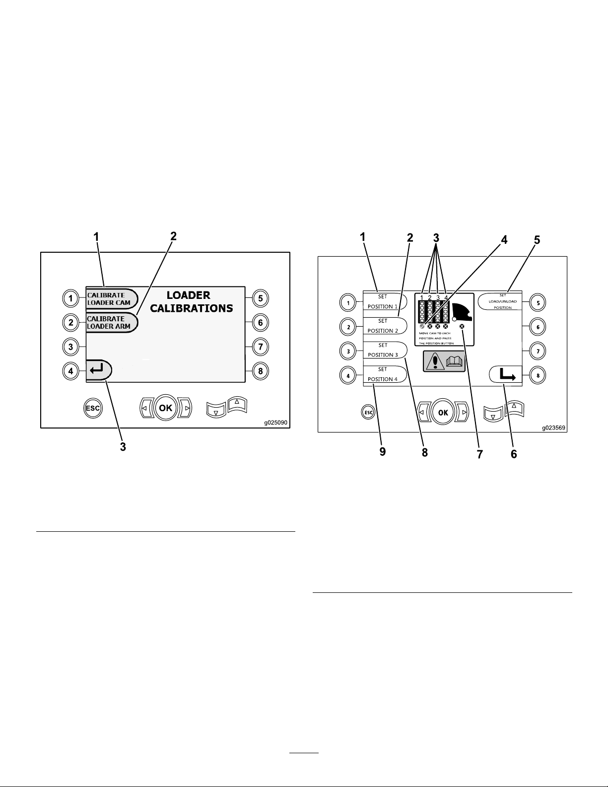
Toaccessthisscreen,pressbuttonnumber6ontheMain
OperatingScreen(page26).
Thisscreenallowsyoutocalibratetheloadercamorto
calibratetheloaderarm.
Thisscreenalsoallowsyoutoadjustthecam-stoppositions,
ensuringthatthecamisinlinewiththepiperow .
Pressthefollowingbuttonstocalibratetheloadercamor
loaderarm:
•Pressbuttonnumber1tocalibratetheloadercam(Figure
29).
•Pressbuttonnumber2tocalibratetheloaderarm(Figure
29).
Toaccessthisscreen,pressbuttonnumber1onthe
Loader-calibrationScreen(page32).
Thisscreenallowstheusertosettherowpositionsforthe
pipeholder.
Pressthefollowingbuttonstosetthedesiredposition:
•Button1—Setposition1(Figure30)
•Button2—Setposition2(Figure30)
•Button3—Setposition3(Figure30)
•Button4—Setposition4(Figure30)
Tosettheloadorunloadposition,pressbuttonnumber5
(Figure30).
1.Calibrateloadercam
2.Calibrateloaderarm
Figure29
Loader-calibrationScreen
3.Returntothe
Main-selectionScreen
Figure30
Loader-cam-calibrationScreen
1.Setposition1
2.Setposition27.Loadercamnotset(Xin
3.Rownumber
4.Rowselectedcheckmark
5.Setload/unloadposition
6.Returntotheprevious
screen
circle)
8.Setposition3
9.Setposition4
32
Page 33

Loader-arm-calibrationScreen
1
2
3
4
5
6
7
8
OK
ESC
1
2
3
4
5
6
7
8
OK
ESC
Clear-service-reminderScreen
Toaccessthisscreen,pressbuttonnumber2onthe
Loader-calibrationScreen(page32).
ThisscreenallowstheusertosettheloaderarmtotheIn
position(fullyinwardtowardthemachine),ortotheHome
position(fullyoutawayfromthemachine).
PressthefollowingbuttonssettheloaderarmtotheInor
Homeposition:
•Button1—SetarmIn(Figure31)
•Button2—SetarmHome(Figure31)
Toaccessthisscreen,pressbuttonnumber7ontheMain
OperatingScreen(page26).
Toclearaservicereminder,enterthe8-digitPIN(13236573)
intothisscreen(Figure32):
Figure32
Enter-PINScreen
1.SetarmIn
2.SetarmHome
Afterenteringthe8-digitPIN,thefollowingscreenwill
appearstatingthatthemaintenancereminderhasbeen
cleared(Figure33).
Figure31
Loader-arm-calibrationScreen
3.Returntotheprevious
screen
Figure33
Maintenance-clearedScreen
33
Page 34

RotaryandCarriage-serviceScreen
Auxiliary-activationsScreen
FromtheMainOperatingScreen(page26),pressbutton
numbers1and5simultaneouslytoaccessthisscreen.
Therotaryandcarriageservicescreen(Figure34)provides
thefollowinginformation:
Figure34
•Rotaryandcarriagejoystickoutput
•Makeuppercentageandoutput(forupperwrench)
•Breakoutpercentageandoutput(forupperwrench)
•Thrustpercentageandoutput
PressthedownarrowontheRotaryandCarriage-service
Screen(page34)toaccessthisscreen.
Theauxiliary-activationsscreen(Figure35)providesthe
followinginformation:
Figure35
•OnandOffindicatorsforclamps,wrenchbreakout(for
upperwrench),TJCapplicator,setup,piperotation,pipe
arms,pipegrip,andpipeelevator
•Multifunctionpercentageandoutput
•Pullbackpercentageandoutput
•OnandOffindicatorsfortwo-speed,seatswitch,cam
rotation,carriageback,andarmsout
34
Page 35

Drilling-uid-informationScreen
Track-drive-informationScreen
PressthedownarrowontheAuxiliary-activations
Screen(page34)toaccessthisscreen.
Thedrilling-uid-informationscreen(Figure36)providesthe
followinginformation:
Figure36
•OnandOffindicatorsfordrillinguid,owincrease,
owdecrease,andmudmax
PressthedownarrowontheDrilling-uid-information
Screen(page35)toaccessthisscreen.
Thetrack-drive-informationscreen(Figure37)providesthe
followinginformation:
Figure37
•Outputforleftforward,leftreverse,rightforward,and
rightreversemovementsofthetrackdrive
•OnandOffindicatorsforseatswitchandsetup
•Drillinguidpercentageandoutput
•Front-Neutral-Reverse(FNR)andsteerjoystickoutput
•OnandOffindicatorsforsetupandseatswitch
35
Page 36

ControlPanel
g021834
1
2
3
4
5
6
7
8
9
10
Figure38
1.Engine-stopbutton
2.Exit-sidelockout—reset
light
3.Exit-side
lockout—drill-enabled
light
4.Receiver-battery-status
light
5.Engine-startbutton10.Engine-speedswitch
6.Ground-strike-resetswitch
7.Exit-side-lockout—reset
switch
8.Drive/drillswitch
9.Lightsswitch
Transmitter-battery-statusLight
Thislight(Figure38)illuminatesredwhenthebatteryon
theexit-side-lockouttransmitteristoolowtotransmit.Stop
drillingoperationsandxtheproblemwiththetransmitter
beforecontinuing.
Engine-startButton
Pressthisbutton(Figure38)tostarttheengine.Thekey
switchontherear,controlpanelmustbeintheOnposition.
Engine-stopButton
Pressthisbutton(Figure38)toimmediatelystoptheengine
andalldrillingoperations.Youmustpullthisbuttonout
beforeyoucanstarttheengineagain.
Ground-strike-resetSwitch
Pressthisswitch(Figure38)toresettheZap-Alertsystem
afteragroundstrikehasoccurredandbeenxed;referto
DeployingtheZap-alertSystem(page66).
Drive/DrillSwitch
Pressthetopofthisswitch(Figure38)toenablethedriveand
setupcontrolsorthebottomtoenabledrillandpipe-loader
functions.
LightsSwitch
Pressthetopofthisswitch(Figure38)toturnthemachine
lightsonorthebottomofthisswitchtoturnthemoff.
Engine-speedSwitch
•Pressandholdthetopofthisswitchtoincreasethe
Exit-sideLockout—ResetLight
Thislight(Figure38)illuminatesyellowwhentheexit-side
lockoutfunctionisturnedoffonexit-side-lockouttransmitter,
indicatingthatyoumayresetthesystem.
Exit-sideLockout—Drill-enabledLight
Thislight(Figure38)illuminatesgreenwhenthe
exit-side-lockoutfeaturehasbeenturnedoffandresetand
themachineisreadytodrill.
enginespeed.
•Pressandholdthebottomofthisswitchtodecreasethe
enginespeed.
•Releasetheswitchtomaintainthecurrentenginespeed.
Exit-sideLockout—ResetSwitch
Pressthisswitch(Figure38)toenabledrillingoperationwhen
theresetlightilluminates.
36
Page 37

LeftJoystick—ModeI
g021833
5
6
7
8
9
4
2
3
1
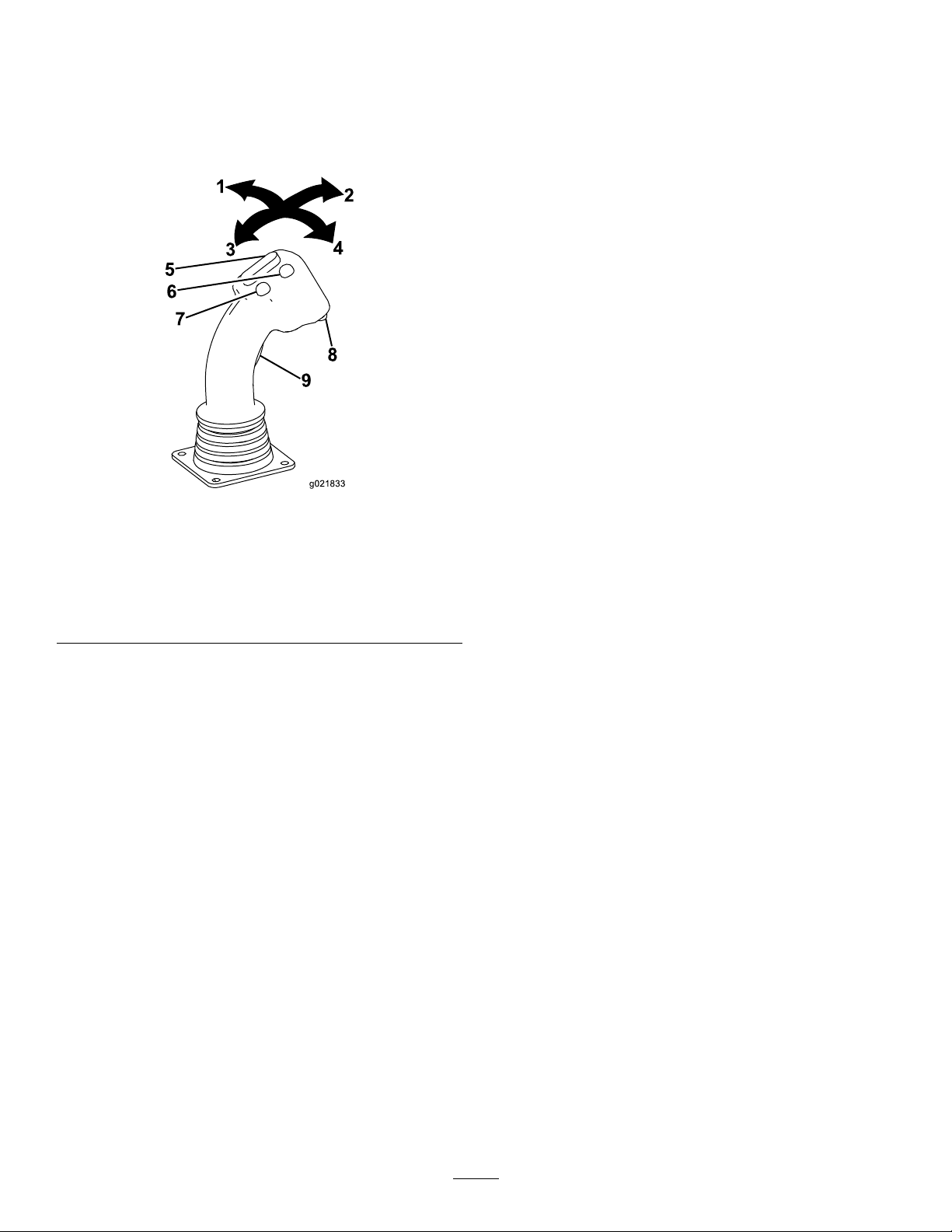
FrontButton
Note:Thejoystickcontrolsvarydependingonthecontrol
modeyouselectwhenpoweringupthemachine.Thereare
2controlmodes:ModeIandModeII;refertotheMain
DrillFunctionsDisplayedinPressureScreen(page27)for
informationonsettingthecontrolmode.
Figure39
1.Joystick—moveleft
2.Joystick—moveforward
3.Joystick—moverearward8.Lowerbutton
4.Joystick—moveright9.Trigger
5.Toggleswitch
6.Frontbutton
7.Rearbutton
•Lefttriggerpressed—pressthisbuttontoresumethe
previouslysetauto-drillspeed.Pressandholdthisbutton
toincreasetheauto-drillspeed.
•Lefttriggerreleased—pressthisbuttontoopenthepipe
gripper.
RearButton
•Lefttriggerpressed—pressthisbuttontosettheauto
drillspeed.Pressandholdthisbuttontodecreasethe
auto-drillspeed.
•Lefttriggerreleased—pressthisbuttontoclosethepipe
gripper.
LowerButton
Ifthesensorfails,usethisbuttontooverridethepipecam
presetsandmanuallymovethecam.Operateinthismode
onlywhennecessary;youcoulddamagethepipecamorpipes
ifyoudonotalignthemcorrectly.Ifthesensorfails,contact
yourAuthorizedToroDealerforrepair.
Joystick—Forward
•Lefttriggerpressed—closesthelowerwrench(stationary
wrench).
•Lefttriggerreleased—retractsthepipegrippertoward
thepipeholder.
Joystick—Rearward
Trigger
Thetriggerchangestheotherjoystickcontrolsfrom
pipe-loadercontrolstowrench-operationcontrols.
wrench).
•Lefttriggerreleased—extendsthepipegrippertoward
thedrillframe.
•Pressthetriggertoenablethewrenchcontrols.
•Lefttriggerpressed—opensthelowerwrench(stationary
•Releasethetriggertoenablethepipe-loadercontrols.
Joystick—Left
•Lefttriggerpressed—openstheupperwrench
ToggleSwitch
•Lefttriggerpressed—rocktheswitchforwardto
rotatetheupperwrench(makeup/breakoutwrench)
clockwisetoloosenajoint;rocktheswitchrearward
torotatetheupperwrench(makeup/breakoutwrench)
counterclockwisetotightenajoint.
•Lefttriggerreleased—rocktheswitchforwardtorotate
thepipecamouttowardthebasket;rocktheswitch
rearwardtorotatethepipecamtowardthedrillframe.
(makeup/breakoutwrench).
•Lefttriggerreleased—lowersthepipeelevator.
Joystick—Right
•Lefttriggerpressed—closestheupperwrench
(makeup/breakoutwrench).
•Lefttriggerreleased—raisesthepipeelevator.
37
Page 38

LeftJoystick—ModeII
g021833
5
6
7
8
9
4
2
3
1
FrontButton
Note:Thejoystickcontrolsvarydependingonthecontrol
modeyouselectwhenpoweringupthemachine.Thereare
2controlmodes:ModeIandModeII;refertotheMain
DrillFunctionsDisplayedinPressureScreen(page27)for
informationonsettingthecontrolmode.
Figure40
1.Joystick—moveleft
2.Joystick—moveforward
3.Joystick—moverearward8.Lowerbutton
4.Joystick—moveright9.Trigger
5.Toggleswitch
6.Frontbutton
7.Rearbutton
•Lefttriggerpressed—pressthisbuttontoresumethe
previouslysetauto-drillspeed.Pressandholdthisbutton
toincreasetheauto-drillspeed.
•Lefttriggerreleased—pressthisbuttontoopenthepipe
gripper.
RearButton
•Lefttriggerpressed—pressthisbuttontosettheauto
drillspeed.Pressandholdthisbuttontodecreasethe
auto-drillspeed.
•Lefttriggerreleased—pressthisbuttontoclosethepipe
gripper.
LowerButton
Ifasensorfails,usethisbuttontooverridethepipecam
presetsandmanuallymovethecam.Operateinthismode
onlywhennecessary;youcoulddamagethepipecamorpipes
ifyoudonotalignthemcorrectly.Ifthesensorfails,contact
yourAuthorizedToroDealerforrepair.
Joystick—Forward
Pushthejoystickforwardtospinthedrillspindle
counterclockwise.
Joystick—Rearward
Pullthejoystickrearwardtospinthedrillspindleclockwise.
Trigger
Joystick—Left
•Lefttriggerpressed—openstheupperwrench
Thetriggerchangestheotherjoystickcontrolsfrom
pipe-loadercontrolstowrench-operationcontrols.
(makeup/breakoutwrench).
•Lefttriggerreleased—extendsthepipegrippertoward
•Pressthetriggertoenablethewrenchcontrols.
thedrillframe.
•Releasethetriggertoenablethepipe-loadercontrols.
Joystick—Right
ToggleSwitch
•Lefttriggerpressed—rocktheswitchforwardto
rotatetheupperwrench(makeup/breakoutwrench)
clockwisetoloosenajoint;rocktheswitchrearward
•Lefttriggerpressed—closestheupperwrench
(makeup/breakoutwrench).
•Lefttriggerreleased—retractsthepipegrippertoward
thepipeholder.
torotatetheupperwrench(makeup/breakoutwrench)
counterclockwisetotightenajoint.
•Lefttriggerreleased—rocktheswitchforwardtorotate
thepipecamouttowardthebasket;rocktheswitch
rearwardtorotatethepipecamtowardthedrillframe.
38
Page 39
RightJoystick—ModeI
g021833
5
6
7
8
9
4
2
3
1
LowerButton
Note:Thejoystickcontrolsvarydependingonthecontrol
modeyouselectwhenpoweringupthemachine.Thereare
2controlmodes:ModeIandModeII;refertotheMain
DrillFunctionsDisplayedinPressureScreen(page27)for
informationonsettingthecontrolmode.
Figure41
1.Joystick—moveleft
2.Joystick—moveforward
3.Joystick—moverearward8.Lowerbutton
4.Joystick—moveright9.Trigger
5.Toggleswitch
6.Frontbutton
7.Rearbutton
Pressthisbuttontoturnthedrilling-uidpumponoroff.
Trigger
Pressandholdthetriggertomovethedrillcarriageathigh
speedupordownthedrillframe.
Joystick—Forward
Pushthejoystickforwardtothrustthedrillcarriageforward.
Joystick—Rearward
Pullthejoystickrearwardtopullthedrillcarriagerearward.
Joystick—Left
Pushthejoysticklefttospinthedrillspindleclockwise.
Joystick—Right
Pushthejoystickrighttospinthedrillspindle
counterclockwise.
ToggleSwitch
Rocktheswitchforwardtoincreasetheowrateofthe
drillinguid;rocktheswitchrearwardtodecreasetheow
rateofthedrillinguid.
Note:Beforeusingthisfeatureyoumustrstturnon
thedrilling-uidpumpusingthelowerbuttonontheright
joystick.
FrontButton
Pressthisbuttontoapplythread-jointcompound.
RearButton
Pressandholdthisbuttonformaximumdrillinguid
pressure;usethistoquicklyllthepipewithdrillinguid
afteraddingorremovingapipe.Releasethebuttontostop
theoworreturntothepreviouslysetowrate.
39
Page 40

RightJoystick—ModeII
g021833
5
6
7
8
9
4
2
3
1
LowerButton
Note:Thejoystickcontrolsvarydependingonthecontrol
modeyouselectwhenpoweringupthemachine.Thereare
2controlmodes:ModeIandModeII;refertotheMain
DrillFunctionsDisplayedinPressureScreen(page27)for
informationonsettingthecontrolmode.
Figure42
1.Joystick—moveleft
2.Joystick—moveforward
3.Joystick—moverearward8.Lowerbutton
4.Joystick—moveright9.Trigger
5.Toggleswitch
6.Frontbutton
7.Rearbutton
Pressthisbuttontoturnthedrilling-uidpumponoroff.
Trigger
Pressandholdthetriggertomovethedrillcarriageathigh
speedupordownthedrillframe.
Joystick—Forward
Pushthejoystickforwardtothrustthedrillcarriageforward.
Joystick—Rearward
Pullthejoystickrearwardtopullthedrillcarriagerearward.
Joystick—Left
•Lefttriggerpressed—opensthelowerwrench(stationary
wrench).
•Lefttriggerreleased—raisesthepipeelevator.
Joystick—Right
•Lefttriggerpressed—closesthelowerwrench(stationary
wrench).
•Lefttriggerreleased—lowersthepipeelevator.
ToggleSwitch
Rocktheswitchforwardtoincreasetheowrateofthe
drillinguid;rocktheswitchrearwardtodecreasetheow
rateofthedrillinguid.
Note:Beforeusingthisfeatureyoumustrstturnon
thedrilling-uidpumpusingthelowerbuttonontheright
joystick.
FrontButton
Pressthisbuttontoapplythread-jointcompound.
RearButton
Pressandholdthisbuttonformaximumdrillinguid
pressure;usethistoquicklyllthepipewithdrillinguid
afteraddingorremovingapipe.Releasethebuttontostop
theoworreturntothepreviouslysetowrate.
40
Page 41
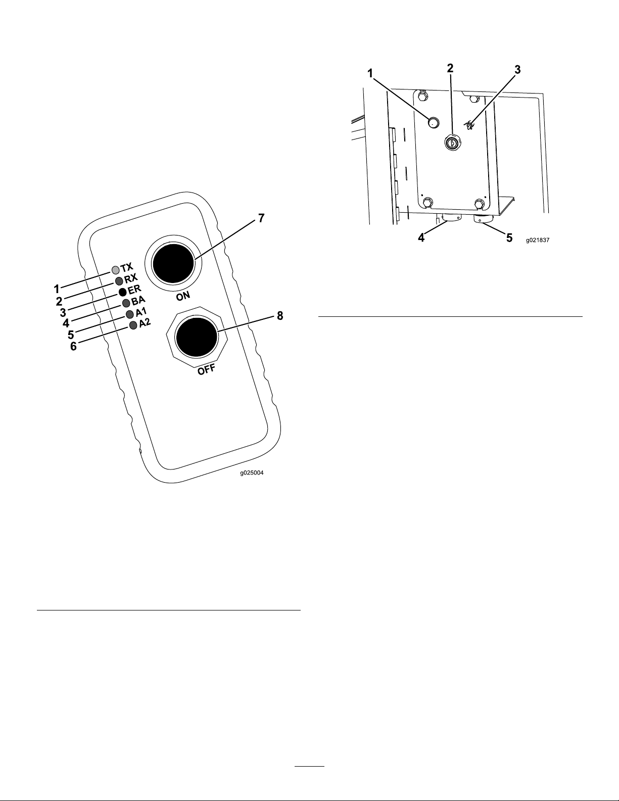
Exit-side-lockoutSystem
g021837
1
2
3
4
5
Theexit-side-lockoutsystemprovidestheindividualsworking
aroundthemachinewithameanstodisablethedrillpipe
fromrotatingandthrusting.
Thissystemconsistsofareceivermountedonthemachine
andatransmitter(Figure43)thatmustbeheldbyadesignated
individualworkingaroundthemachine.
RefertoUnderstandingandUsingtheExit-side-lockout
System(page55)forinformationonunderstandingand
operatingthebaseunitandthehandheldunitforthe
exit-side-lockoutsystem.
RearControlPanel
Figure44
1.Engine-heatinglight4.Drill-pendantreceptacle
2.Engine,keyswitch5.Drive-pendantreceptacle
3.Fluid-pumpswitch
1.Transmit(TX)—green
indicatorlight
2.Receive(RX)—yellow
indicatorlight
3.Error(ER)—redindicator
light
4.Lowbattery(BA)—yellow
indicatorlight
Engine-heatingLight
Whentheengineiscold,theheaterwarmstheintakeairto
enableeasierstarting.Thislightilluminateswhiletheheateris
on.Waituntilthislightturnsoffbeforestartingtheengine.
Figure43
5.Auxiliary1(A1)—yellow
indicatorlight
6.Auxiliary2(A2)—yellow
indicatorlight
7.Onbutton
8.Offbutton
41
Page 42

EngineKeySwitch
1
2
3
G0221 15
Thekeyswitchhas3positionsasfollows(Figure45):
Figure45
DrillFrameandStabilizerControls
1.Engine-offposition
2.Engine-runposition
3.Engine-startposition
•Engine-offposition—turnthekeytothispositiontostop
theengine.Youcannotstarttheenginefromtheoperator
platformwhenthekeyisinthisposition.
•Engine-runposition—turnthekeytothispositionafter
startingtheengine.Turningthekeytothisposition
alsoenablestheenginestartbuttonfromtheoperator
platform.
•Engine-startposition—turnthekeytothispositionto
starttheengine.ReleasethekeytotheRunpositiononce
theenginehasstarted.
Fluid-pumpSwitch
Usethisswitchtoturnontheuidpumptousethespraygun
whencleaningthemachine(Figure44).
Drill-pendantReceptacle
Plugthedrillpendantintothisreceptacletoattachittothe
machine(Figure44).
Drive-pendantReceptacle
Figure46
1.Drill-frametiltlever
2.Left-stabilizerlever
StabilizerLevers
3.Right-stabilizerlever
Usethestabilizerleverstoraiseandlowerthestabilizers.
Note:TheDrive/Drillswitchontheoperatorpanelmustbe
switchedtotheDrivepositionforthisfunctiontowork.
Drill-frameTiltLever
Usethedrill-frametiltlevertotiltthedrillframetoplace
thestake-downplateonthegroundortoreturntheframe
tothetravelposition.
Note:TheDrive/Drillswitchontheoperatorpanelmustbe
switchedtotheDrivepositionforthisfunctiontowork.
Plugthedrivependantintothisreceptacletoattachittothe
machine(Figure44).
42
Page 43

DrivePendant
g021855
1
2
4
3
5
Operator-presenceSwitch
RefertoFigure44forthelocationofthedrivependant.
Pressandholdthisbuttontoenabletheothercontrolsonthe
drivependant.Themachinewillstopmovingifyourelease
thisbutton.
Figure47
1.Engine-speedswitch4.Drive-speedswitch
2.Drive-directionjoystick
3.Engine-stopbutton
Engine-stopButton
5.Operator-presenceswitch
Pressthisbuttontoimmediatelystoptheengineandall
movement/drillingoperations.Youmustpullthisbuttonout
beforeyoucanstarttheengineagain.
Engine-speedSwitch
•Pressandholdthetopofthisswitchtoincreasethe
enginespeed.
•Pressandholdthebottomofthisswitchtodecreasethe
enginespeed.
•Releasetheswitchtomaintainthecurrentenginespeed.
Drive-directionJoystick
Usethejoysticktocontrolthedirectionofthemachine.The
machinewilltravelinthedirectionthatyoumovethejoystick.
Drive-speedSwitch
Theswitchsetsthespeedatwhichthemachinewilltravel.
Movetheswitchupforhighspeedordownforlowspeed.
43
Page 44
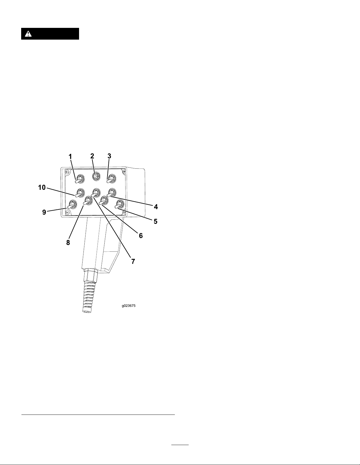
DrillPendant
Left-track-controlSwitch/Rotary-controlSwitch
WARNING
Onlyanauthorizedperson(s)shouldoperatethe
drillpendant.Personalinjury,harmtoothers,or
damagetothemachinecouldoccurifthispendant
ismisused.
Thedrillpendant(alsoreferredtoasthelife-jacketpendant)
isdesignedtoallowyourudimentarycontroloverthedrilling
featureswhenconnectedtothefrontreceptacle,shouldthe
operatorplatformcontrolsbecomenon-responsive.Youcan
alsoplugthispendantintothedrive-pendantreceptacleat
therearcontrolpanel,intheeventthatthedrivependant
malfunctionstoobtainbasicmovementfunctionsatslow
speed.
RefertoFigure44forthelocationofthedrillpendant.
Whenthisswitchisconnectedtothedrive-pendant
receptacle,moveittocontrolthemovementoftheleft
track.
•Movetheswitchforwardtomovethelefttrackforward.
•Movetheswitchbackwardtomovethelefttrack
backward.
Whenthisswitchisconnectedtothefrontdrill-pendant
receptacle,moveittocontroltherotationofthepipe.
•Movetheswitchforwardtorotatethepipeclockwise.
•Movetheswitchbackwardtorotatethepipe
counterclockwise.
DrillingFluidandWrench-controlSwitch
Whenthisswitchisconnectedtothefrontdrill-pendant
receptacle,moveittocontrolthedrilling-uidowor
thewrenchoperation.
•Movetheswitchtothelefttoturnthedrillinguidto
theOnposition.
•Movetheswitchtotherighttoturnwrenchoperationto
theOnposition.
1.Left-track-control
switch/rotary-control
switch
2.Drillinguidand
wrench-controlswitch
3.Right-track-control
switch/carriage-control
switch
4.Breakout-wrench-control
switch(upperwrench)
5.Drill-spindle-controlswitch
Figure48
6.Pipe-grip-controlswitch
7.Pipe-clamp-controlswitch
8.Cam-rotation-control
9.Pipe-elevator-control
10.Stationary(for
switch
switch
lowerwrench)
pipe-clamp-controlswitch
Right-track-controlSwitch/Carriage-controlSwitch
Whenthisswitchisconnectedtothedrive-pendant
receptacle,moveittocontrolthemovementoftheright
track.
•Movetheswitchforwardtomovetherighttrackforward.
•Movetheswitchbackwardtomovetherighttrack
backward.
Whenthisswitchisconnectedtothefrontdrill-pendant
receptacle,moveittocontrolthemovementofthe
carriage.
•Movetheswitchforwardtomovethecarriageforward.
•Movetheswitchbackwardtomovethecarriagebackward.
Breakout-wrench-controlSwitch
Whenthisswitchisconnectedtothefrontdrill-pendant
receptacle,moveittocontrolthewrenchbreakoutand
makeup.
•Movetheswitchforwardforwrenchbreakout(forupper
wrench).
•Movetheswitchbackwardforwrenchmakeup(forupper
wrench).
44
Page 45

Drill-spindle-controlSwitch
g021835
1
2
3 4
Whenthisswitchisconnectedtothefrontdrill-pendant
receptacle,moveittocontrolthemovementofthedrill
spindle.
•Movetheswitchforwardtorotatethedrillspindle
backwardtowardthepipeholder.
•Movetheswitchbackwardtorotatethedrillspindle
forwardtowardtheoperator.
Pipe-grip-controlSwitch
Whenthisswitchisconnectedtothefrontdrill-pendant
receptacle,moveittocontrolthepipegrip.
•Movetheswitchforwardtotightenthegriponthepipe.
•Movetheswitchbackwardtoloosenthegriponthepipe.
Pipe-clamp-controlSwitch
Stake-downLevers
1.Left-stake-raise/lower
lever
2.Left-stake-spinlever
Figure49
3.Right-stake-raise/lower
lever
4.Right-stake-spinlever
Whenthisswitchisconnectedtothefrontdrill-pendant
receptacle,moveittocontrolthepipeclamp.
•Movetheswitchforwardtotightentheclamponthepipe.
•Movetheswitchbackwardtoloosentheclamponthe
pipe.
Cam-rotation-controlSwitch
Whenthisswitchisconnectedtothefrontdrill-pendant
receptacle,moveittocontrolthemovementofthecam.
•Movetheswitchforwardtorotatethecambackward
towardthepipeholder.
•Movetheswitchbackwardtorotatethecamforward
towardtheoperator.
Pipe-elevator-controlSwitch
Whenthisswitchisconnectedtothefrontdrill-pendant
receptacle,moveittocontrolthepipeelevator.
•Movetheswitchforwardtoraisethepipeelevator.
•Movetheswitchbackwardtolowerthepipeelevator.
Stake-raise/lowerLevers
Pushdownontheseleverstolowerthestakesintotheground.
Pullupontheseleverstoraisethestakesoutoftheground.
Note:TheDrive/Drillswitchontheoperatorpanelmustbe
switchedtotheDrivepositionforthisfunctiontowork.
Stake-spinLevers
Pushdownontheseleverstospinthestakesclockwise.Pull
upontheseleverstospinthestakescounterclockwise.
Note:TheDrive/Drillswitchontheoperatorpanelmustbe
switchedtotheDrivepositionforthisfunctiontowork.
StationaryPipe-clamp-controlSwitch
Whenthisswitchisconnectedtothefrontdrill-pendant
receptacle,moveittocontrolthestationary-pipeclamp.
•Movethisswitchforwardtotightenthestationary-pipe
clamp(forlowerwrench).
•Movethisswitchbackwardtoloosenthestationary-pipe
clamp(forlowerwrench).
45
Page 46

Battery-disconnectSwitch
Opentherearcompartmenttoaccessthebattery-disconnect
switch.
HandheldunitfortheExit-side-lockout
System(cont'd.)
Turnthebattery-disconnectswitchtotheOnorOffposition
toperformthefollowing:
•Toenergizethemachineelectrically,rotatethe
battery-disconnectswitchclockwisetotheOnposition
(Figure50).
•Tode-energizethemachineelectrically,rotatethe
battery-disconnectswitchcounterclockwisetotheOff
position(Figure50).
Storagetemperature-40°to55°C(-40°to131°F)
Humidity
Radiofrequency
RadioRFpower
Radiolicense
Modulation
AntennaInternal
0to100%
2405to2480MHz
50mW(60GHz)
License-freecertication
pending
DSSS
BaseunitfortheExit-side-lockoutSystem
Operatingtemperature-20°to55°C(-4°to131°F)
Storagetemperature-40°to85°C(-40°to185°F)
Humidity
Radiofrequency
RadioRFpower
Radiolicense
Modulation
AntennaExternal
0to100%
2405to2480MHz
100mW(120GHz)
License-freecertication
pending
DSSS
Figure50
1.Battery-disconnectswitch
(Onposition)
2.Battery-disconnectswitch
(Offposition)
Specications
Note:Specicationsanddesignaresubjecttochange
withoutnotice.
Machine
Width
Length
Height
Weight
9,806kg(21,620lbs)
HandheldunitfortheExit-side-lockout
System
Batteries3AAA
Lowbatterywarning
Inactivitytimeout
Operatingtemperature-20°to55°C(-4°to131°F)
3.2VLED—3ashesfor30
secondspriortoshutdown
Innite
2.2m(7.2ft)
6m(19.7ft)
2.5m(8.2ft)
Attachments/Accessories
AselectionofToroapprovedattachmentsandaccessoriesis
availableforusewiththemachinetoenhanceandexpand
itscapabilities.ContactyourAuthorizedServiceDealeror
Distributororgotowww .Toro.comforalistofallapproved
attachmentsandaccessories.
Important:UseonlyToroapprovedattachments.
Otherattachmentsmaycreateanunsafeoperating
environmentordamagethetractionunit.
46
Page 47

Operation
Note:Determinetheleftandrightsidesofthemachine
fromthenormaloperatingposition.
UnderstandingHorizontal
DirectionalDrilling
Horizontaldirectionaldrillingisaprocessusedfordrilling
ahorizontalborethroughthesoilandunderobstructions
suchasroads,buildings,bodiesofwater,etc.Onceyoudrill
thebore,youpullbacktheutilitylinesorpipesthroughthe
boreandconnectthemasneeded.Becauseitdoesnotgreatly
disturbthesurface,installingutilitiesusingdirectionaldrilling
preservestheenvironmentandsavesbothtimeandmoney
overtraditionalinstallationmethodssuchastrenching.
Installingcablingorpipeusingadirectionaldrillinvolvesthe
followingsteps:
1.Gathersiteinformation.
Beforeoperatinginanareawithhigh-voltagelinesor
cables,contactaOne-CallSystemDirectoryservice.
IntheUSA,call811oryourlocalutilitycompany.If
youdonotknowyourlocalutilitycompany’ sphone
number,callthenationalnumber(USAandCanada
only)at1-888-258-0808.Also,contactanyutility
companiesthatarenotparticipantsoftheOne-Call
SystemDirectoryservice.PleaserefertoDrillingNear
UtilityLines(page6)formoreinformation.
Beforefullyplanningthebore,gatherinformation
aboutthejobsite,suchasthelocationofotherutilities,
obstaclesatthesite,andthepermitsyouwillneedto
completethejob;refertoGatheringSiteInformation
(page48).
2.Planthebore.
Beforeyoudrill,plantheborepathbasedonthe
informationthatyougathered;refertoPlanningthe
BorePath(page50).
3.Preparethejobsiteandthemachine.
Beforedrilling,preparethejobsitewithanentrypoint,
adepth-gaugehole(optional),andanexithole.You
alsoneedtodrivetheunittothesite,setitupfor
drilling,andconnectittoadrilling-uidmixer.
Note:Whendrilling,youconnectthemachinetoa
drilling-uidmixerthatmixeswaterwithbentonite
clayandotheringredients.Themachinepumpsthis
mixture,referredtoasdrillinguidor“mud”,through
thedrillpipeandoutthedrillbit.Thedrillinguid
lubricatesthebit,helpstoholdtheboreopenwhile
drilling,andmixeswiththespoils,ushingthemout
oftheborethroughtheentrypoint.
4.Drillthebore.
Youdrilltheborein3stages:
A.Entry
Intheentryphaseofthebore,youpushthedrill
bitandheadintothegroundatanangleofupto
16degrees.Afterpushinginoneormorepipes,
youbegindrillingdownandforwarduntilyou
reachthedesireddepthordepth-gaugehole(if
used).
B.HorizontalReach
Afterreachingthedesireddepth,youpushthe
bitforward,steeringthebittoahorizontaldepth.
Thedrillbitemitsaradiosignalfromthesonde
housing,whichallowsacrewmemberonthe
surfacetotrackthelocationanddepthofthehead
usingthesondereceiverasyoudrillandsteerit
alongaplannedroute.
C.Exit
Onceyouhaveattainedtheplannedhorizontal
reach,yousteertheheadupatananglesimilar
toyourentryanglebringingthebitintotheexit
holeortrench.
RefertoDrillingtheBore(page67).
5.Backreamtheboreandpullbackcablingorpipe.
Afterenteringtheexithole,theendcrewdetachesthe
drillbitandsondehousingfromthedrillpipe.Inits
place,theyattachareamingbitandtheendofthecable
orpipetobepulledthroughthebore.Thereaming
bitisdesignedtoenlargetheboreasyoupullitback.
Asbefore,youpumpdrillinguidthroughthepipe
tothereamingbitasyoupullthecableorpipeback
throughtheboretolubricatethereamerandallow
thecableorpipetoslideeasilythroughthebore.You
continuepullingthepipebackuntilthereamerreaches
thedepth-gaugeholeorexitsattheentrypoint.There
youremovethereamerandproductfromthedrillpipe,
pullingthepipetherestofthewaybacktothemachine.
RefertoBackreamingandPullback(page71)for
instructionsonbackreamingandpullingcableorpipe.
6.Finishtheboreandleavethejobsite.
Aftercompletingtheoperation,youneedtodisconnect
andcleanthemachineandloaditonthetrailer;referto
CleaningwiththeSpray-hoseAttachment(page113).
RefertoPreparingtheJobSiteandtheMachine(page
57)forinstructionsonpreparingthejobsiteandthe
machine.
47
Page 48

GatheringSiteInformation
PlanningtheInitialRoute
Beforeyoucanbeginboring,youneedtoplantheroutethat
youwillboreandprepareasfollows:
•Createabasicplanforthebore,mappingoutthe
proposedroute.
–Noteanyobstacleswhichmayaffectthebore,such
aslargetrees,bodiesofwater,buildings,etc.
–Plantherouteoftheboretoavoidasmanyobstacles
aspossible.
–Determinethedepthofanybodiesofwatertobe
crossedtoensurethatyoucangetdeepenoughunder
them.
•Determinethedepththatyouneedtoinstallthematerial
atandtheminimumbendradiusbothofthedrillpipe
andofthematerialbeinginstalled.Thiswillseriously
affecthowlongtheboreneedstobeandatwhatangle
thatyoucanbeginandend;refertoPlanningtheBore
Path(page50).
•Havetheareaoftheboremarkedforutilitylines(inthe
UScall811).Ensurethatalllinesaremarkedonyour
blueprints/boreplanaswell.
•Contactthelocalauthoritiestoarrangeforanypermits
andtrafccontrolthatyouwillneedtoconductthejob.
DANGER
Contactingundergroundhazardswiththe
machinewhiledrillingorreamingcancause
explosion,electrocution,breathingproblems,
severetrauma,anddeathtoyouorbystanders.
–Ensurethatallpersonnelatthejobsitewear
personalprotectiveequipmentincluding
ahardhat,eyeprotection,andhearing
protection.
–Keepbystandersandspectatorsawayfrom
thejobsite,includingthecompletebore
path.
–Locateandexposeallelectricandgaslines
thatyouwillbecrossingbycarefulhand
digging.
–EnsurethatyouusetheZap-Alertsystem
wheneveryouoperatethemachine.
Commonhazardsincludethefollowing:
–Gaslines
DANGER
Drillingintoagaslinecancauseanexplosion
orre,burning,injuring,orkillingyouor
othersinthevicinityofthebreak.
InspectingtheProposedJobSite
Physicallyinspectthesiteasfollows:
•Notetheterrain,slopes,valleys,hills,andanyfeatures
notplannedforpreviously.
Determinethedegreeofslopeatboththeproposedentry
pointandexitpoint.
•Determinewhatthesoiltypesareintheareaand,if
possible,atthedepththatyouwillbeboring.Youmay
needtodigtestholesatintervalsalongtheborepathto
fullydeterminethis.
•Walktheareaofthebore,lookingforanypossible
unmarkedobstructions.Lookformanholes,pedestals,
oldfoundations,etc.
•Identifyallthehazardsthatyouwillpasswithin3m(10
ft).
◊Donotsmokeorhaveanysourceofame
neargaslinesorateitherendofabore
thatwillbecrossingagasline.
◊Keepbystandersandspectatorsaway
fromthejobsite,includingthecomplete
borepath.
◊Locateandexposeallgaslinesthatyou
willbecrossingbycarefulhanddigging.
◊Havethegascompanyturnoffthegas
toanylinesyouwillbecrossingbefore
drilling.
◊Usethereceivertotracktheexactposition
ofthedrillheadwhenapproachinggas
lines.
48
Page 49

–Electricalpowerlines
DANGER
Drillingintoanelectricpowerlinewillcause
themachinetobecomeelectriedandmay
electrocuteyouoranybystanders.
–Crystallinesilicaandotherdust
Ifyouwillbedrillingthroughorcuttingconcrete,
sand,orothersubstancesthatcreatedustsorfumes,
youneedtoensurethatyouandallworkerswear
breathingprotectiontoprotectyourlungsfromthe
dust.
◊Keepbystandersandspectatorsaway
fromthejobsite,includingthecomplete
borepath.
◊Locateandexposeallelectriclinesthat
youwillbecrossingbycarefulhand
digging.
◊Havetheelectriccompanyturnoffthe
powertoanylinesyouwillbecrossing
beforedrilling.
◊Usethereceivertotracktheexact
positionofthedrillheadwhen
approachingelectriclines.
◊Beforedrilling,setupandusethe
Zap-alertsystemwhichisdesignedto
notifyinthecaseofanelectricstrikeand
electricallyisolatethemachineoperator
fromthemachine.IftheZap-alertalarm
triggers,stopwhatyouaredoinganddo
notleavetheoperator’sposition.Refer
toTestingtheZap-alertSystem(page
58)fordetailedinstructionsonusingthe
Zap-alertsystem.
WARNING
Machiningorhandlingstone,masonry,
concrete,metal,andothermaterialscan
generatedust,mists,andfumescontaining
chemicals,suchassilica,knowntocause
seriousorfatalinjuryorillness,suchas
respiratorydisease,silicosis,cancer,birth
defects,orotherreproductiveharm.
◊Controldust,mist,andfumesatthe
sourcewherepossible.Watershouldbe
usedfordustsuppressionwhenfeasible.
◊Usegoodworkpracticesandfollowthe
recommendationsofthemanufactureror
suppliers,OSHA,andotheroccupational
andtradeassociations.
◊Whenthehazardsfrominhalationcannot
beeliminated,theoperatorandany
bystandersshouldweararespirator
approvedbyOSHAforthematerialbeing
handled.
WARNING
Silicosis W ar ning:
drillingstone,masonry,concrete,metal,
andothermaterialswithsilicaintheir
compositionmaygiveoffdustormist
containingcrystallinesilica.Silicaisa
basiccomponentofsand,quartz,brick,
clay,granite,andnumerousotherminerals
androcks.Repeatedand/orsubstantial
inhalationofairbornecrystallinesilicacan
causefatalrespiratorydiseases,including
silicosis.Inaddition,someotherauthorities
havelistedrespirablecrystallinesilicaasa
substanceknowntocausecancer.When
cuttingsuchmaterials,followrespiratory
precautions.
Grinding,cutting,or
49
Page 50

PlanningtheBorePath
Beforesettingupthejobsite,youneedtoplantheborepath,
includingthefollowing:
Figure51
1.Boreentry
2.Beginning-of-bore-at-depthpoint5.End-of-bore-at-depthpointandboreexit
3.Boredepth
•Boreentry
Thisiswhereyousetupthemachineandthedrillbit
enterstheground.Dependingonconditions,thiswill
typicallybesetback9to15m(30to50ft)fromthe
beginning-of-the-bore-at-depthpoint.
•Beginning-of-bore-at-depthpoint
Thisisthepointwhereyouwanttheutilitylineorpipeto
endafterinstallationiscomplete.Itistypicallythepointat
whichtheborelevelsoutandbeginstoborehorizontally.
Thismaybethesameastheentrypoint,oryoumaydiga
separatedepth-gaugeholeatthispoint(Figure51).
•Boredepth
Thisthedepthatwhichyouwanttoinstalltheutility
lineorpipe.Thismachineisdesignedprimarilyfor
installationsbetween1and3m(3.5to10ft).
•Obstaclesinthepath
Itisimportanttoknowwheretheknownobstaclesare
thatyouwillneedtosteeraroundorunderbeforestarting
sothatyoucanplanwheretobeginsteeringpriorto
reachingtheobstacle.
•End-of-bore-at-depthpoint
Thisisthepointwhereyouwanttheutilitylineorpipe
tobeginafterinstallationiscomplete.Often,thiswill
alsobetheboreexit.
4.Obstacle
neededforsteeringthedrilltothesurface,typically9to15
m(30to50ft)fromtheend-of-the-bore-at-depthpoint.
DeterminingtheBore-entryPoint
Oneofthemorechallengingaspectsofplanningthebore
pathistodeterminetheentrypointofthebore.Youneedto
takethefollowingtraitsintoaccountwhendeterminingthe
locationoftheentrypoint:
•Boredepth
Thisisthedepthatwhichyouwanttoinstalltheutility
lineorpipe.Thismachineisdesignedprimarilyfor
installationsbetween1and3m(3.5to10ft).
•Pipeandmaterialexibility
The3m(10ft)pipesusedonthismachinecanexto
an8%pitchoverthelengthofthepipe;thisequatesto
abendofnomorethan20cm(8inches)offastraight
path(Figure52).
Important:Ifyousteerthepipetobendsharper
than20cm(8inches)perpipe,youmaydamagethe
pipesandtheirconnections.Youmustalsomake
steeringchangesgraduallyovertheentirelengthof
eachpipe.Ifyousteerthewhole20cm(8inches)
inonly25to50cm(1to2ft)oftravel,youwill
permanentlydamagethepipes.
•Boreexit
Thisisthelocationwherethedrillheadwillexitthe
groundandthepointatwhichyouwillpulltheutilitylines
orpipeintothebore.Ifthispointwillbeatthesurface
insteadofatinstallationdepth,youwillneedtodetermine
thedistancefromtheend-of-bore-at-depthlocation
50
Page 51

1
g021765
Figure52
1
2
3
g021766
2
3
g021767
1
1.20cm(8inches)
Thisexibilityisoftenratedinmaterialsasaminimum
bendradius,whichistheradiusofthecircleformedifthe
materialorpipes,connectedtogether,werebenttoform
agiantcircle.Theminimumradiusofacirclemadewith
thepipeusedwiththismachineis36.6m(102ft).
•Entrypitch
Theentrypitchistheangleatwhichthemachine
enterstheground.Withthetracksonlevelground,the
stabilizersdown,andthestake-downplateontheground,
thedrillframeangleisabout15degreesora27%pitch.
Thispitchwillchangedependingontheslopeofthe
groundandotherfactorsofthejobsite.Youcanalso
reducethispitchabitbybuildingupthegroundunder
thestake-downplatebeforepositioningthemachine.
Youcandeterminetheactualpitchofthedrillframeby
placingthedrillbitandsondehousingontheframeand
thenusethereceivertodisplaythepitch.
Thesteepertheentrypitchis,thedeepertheborewill
havetobeduetothelimitationsofthepipeexibility.
Typicallyyouneedtoinsertthedrillandatleast1/3ofa
pipeintothegroundbeforeyoucanstartsteeringtoward
thebeginningoftheborepoint.Figure53,Figure54,
andthefollowingtableillustratetherelationshipbetween
entrypitchanddepth.
Figure53
1.26%pitch3.76cm(30inches)
2.3m(10ft)
Figure54
1.18%pitch3.53cm(21inches)
2.3m(10ft)
51
Page 52

Note:Thedepthsgiveninthefollowingtablearefor3m(10ft)ofcombineddrillheadandpipe.Asyousteerup,the
pitchofthesteeredsectionwillchangeandcanbemonitoredwiththereceiver.Usethefollowingtabletoidentifyhow
manylengthsofpipewillbenecessarytoinsertandsteertothebeginningpointandhelpyouchooseanentrypoint.
Pitch
1%2cm(1inch)26%76cm(30inches)
2%5cm(2inches)27%79cm(31inches)
3%10cm(4inches)28%81cm(32inches)
4%13cm(5inches)29%84cm(33inches)
5%15cm(6inches)30%86cm(34inches)
6%18cm(7inches)31%91cm(36inches)
7%20cm(8inches)32%94cm(37inches)
8%25cm(10inches)33%97cm(38inches)
9%28cm(11inches)34%99cm(39inches)
10%30cm(12inches)35%102cm(40inches)
11%33cm(13inches)36%104cm(41inches)
12%36cm(14inches)37%107cm(42inches)
13%39cm(15inches)38%109cm(43inches)
14%43cm(17inches)39%112cm(44inches)
15%46cm(18inches)40%114cm(45inches)
16%48cm(19inches)41%117cm(46inches)
17%51cm(20inches)42%117cm(46inches)
18%53cm(21inches)43%119cm(47inches)
19%56cm(22inches)44%122cm(48inches)
20%61cm(24inches)45%124cm(49inches)
21%64cm(25inches)46%127cm(50inches)
22%66cm(26inches)47%130cm(51inches)
23%69cm(27inches)48%133cm(52inches)
24%71cm(28inches)49%135cm(53inches)
25%74cm(29inches)50%137cm(54inches)
Allmeasurementsareapproximateandwillvarydependingonsoilconditions.
DepthChangeper10feet
Pitch
DepthChangeper10feet
Note:ThesevaluesandmorecanbefoundintheDriller’ sHandbook&DailyLogbyDigitalControlIncorporated.
52
Page 53

Giventheaboveinformation,youcancalculatethenumberof
rodsrequiredtoreachyourbeginningpointattheappropriate
depth.Tororecommendsthatyoustarttheentrypointthe
samedistancebackfromyourbeginning-at-depthpointas
thelengthofpipesyouwillneedtoreachthatpoint.Thiswill
ensurethatyouhaveenoughextraspacesoyouwillnotneed
toover-steeranddamagethepipes.
1.26%pitch4.185cm(73inches)7.14.7m(45ft)
2.76cm(30inches)5.203cm(80inches)
3.142cm(56inches)6.208cm(82inches)
Thefollowingexampleillustratestheprocessgivenan
installationusingthemaximumentrypitchofthemachine
(26%)onlevelground:
•Inserttherst3m(10ft)ofdrillbit/pipeintotheground
withnosteering.Theendofthedrillbitwillbe76cm
(30inches)deep(Figure52).
Figure55
•Beginsteeringupforthenext3m(10ft),pushingthe
pipesinatthemaximumpitchchangeof8%.Thisresults
inachangeofpitchfrom26%atthebeginningofthe3m
(10ft)to18%attheendofthe3m(10ft)foranaverage
pitchof22%.Giventhat,thedrillheadlowersanother66
cm(26inches)andisnow142cm(56inches)deep.
•Continuingsteeringupforthenext3m(10ft)atan8%
pitchchange,yourpitchwillchangefrom18%to10%
foranaveragepitchof14%.Giventhat,thedrillhead
lowersanother43cm(17inches)andisnow185cm(73
inches)deep.
•Continuingsteeringupforthenext3m(10ft)atan8%
pitchchange,yourpitchwillchangefrom10%to2%for
anaveragepitchof6%.Giventhat,thedrillheadlowers
another18cm(7inches)andisnow203cm(80inches)
deep.
•Levelingthedrillheadfrom2%to0%takeslessthan1.5
m(5ft)moreforanaldepthof208cm(82inches).
Reachingthisnalpointtook4-1/2pipes3m(10ft)
long.Soforthisexample,yourentrypointshouldbe14.7
m(45ft)backfromthebeginning-at-depthpointofyour
installation.
53
Page 54

Thefollowingexampleillustratestheprocessgivenan
installationusingthemachineatan18%pitchonlevel
ground:
1.18%pitch3.96cm(38inches)5.119cm(47inches)
2.53cm(21inches)4.114cm(45inches)6.10.6m(35ft)
•Inserttherst3m(10ft)ofdrillbit/pipeintotheground
withnosteering.Theendofthedrillbitwillbe53cm
(21inches)deep(Figure56).
Figure56
•Beginsteeringupforthenext3m(10ft),pushingthe
pipesinatthemaximumpitchchangeof8%.Thisresults
inachangeofpitchfrom18%atthebeginningofthe3m
(10ft)to10%attheendofthe3m(10ft)foranaverage
pitchof14%.Giventhat,thedrillheadlowersanother43
cm(17inches)andisnow96cm(38inches)deep.
•Continuingsteeringupforthenext3m(10ft)atan8%
pitchchange,yourpitchwillchangefrom10%to2%for
anaveragepitchof6%.Giventhat,thedrillheadlowers
another18cm(7inches)andisnow114cm(45inches)
deep.
•Levelingthedrillheadfrom2%to0%takeslessthan1.5
m(5ft)moreforanaldepthof119cm(47inches).
Reachingthisnalpointtook3-1/2pipes3m(10ft)
long.Soforthisexampleyourentrypointshouldbe10.6
m(35ft)backfromthebeginning-at-depthpointofyour
installation.
Important:Youcanusetheinformationcontainedin
thissectiontodetermineboththespaceneededtosteer
uptotheexitpointifneededandalsotosteeraround
obstacles.
MappingtheBore
Withtheinformationyougatheredpreviously,mapoutthe
routeofthebore,identifyingthefollowingsothatyoucan
markthesitelater:
•Entrypoint
•Locationofthemachineandsupportingequipment
•Beginningofboreatdepth
•Anyobstaclesthatyouneedtosteeraroundandthe
locationswhereyouneedtostartsteeringtogetaround
orunderthem
•Anyutilitylinesthatyouwillneedtocross
•Slopeandsoilchangesalongthepaththatwillaffectthe
bore
•Endoftheboreatdepth
•Exitlocationifdifferentthantheendofthebore
54
Page 55

UnderstandingandUsingthe Exit-side-lockoutSystem
UnderstandingtheBase-unit
TransmitterIndicatorLights
Thefollowingtableliststhevariousstatesoftheindicator
lightsonthebase-unittransmitter(Figure57)andtheir
meanings:
IndicatorLightMeaning
UnmarkedindicatorlightInputpowerpolarityreverse
+V1to+V3
RTXBlinkingwhentransmitting
RRXActivewhenreceiving
Overtemp/voltage
HTH
UndercurrentLightsupwhenthecurrentis
OutOutputisactivewhenlit
NotusedUnused
InInputisactivewhenlit
whenlit
OKandactivewhensolid
Lightsupwhenthe
temperatureorvoltageis
exceeded
OKwhenblinking
toolow
Figure57
1.Polarity-reversalindicator
2.+V18.HTH
3.+V29.Undercurrent
4.+V3
5.RTX11.Notused
6.RRX12.In
7.Overtemperature/voltage
10.Out
55
Page 56
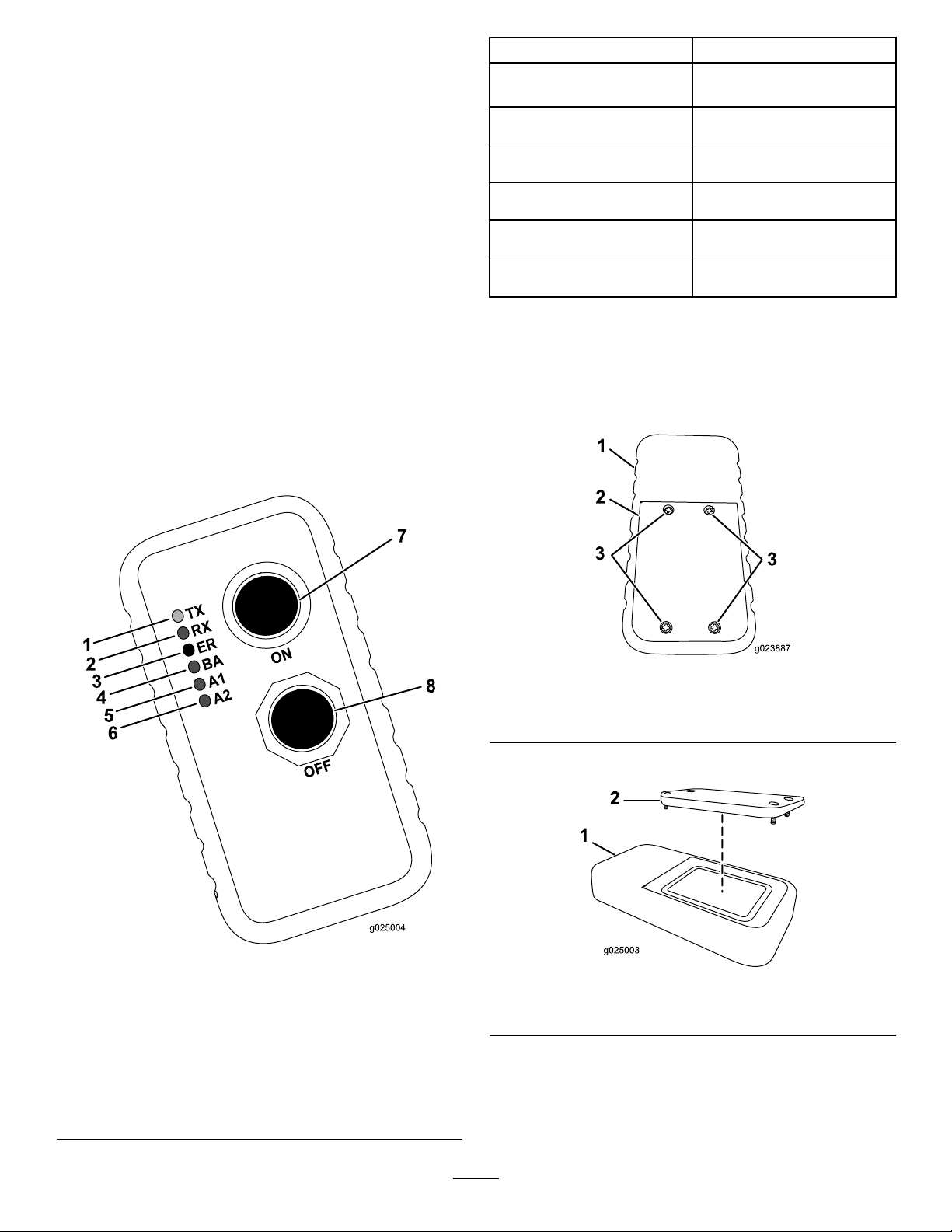
UnderstandingandUsingtheHandheld
TransmitterIndicatorLights
TheindividualholdingthetransmittercanpushtheLock
Drill(Off)buttontostopthedrillrotationandthrust.This
isprimarilyusedtostop/lockoutthedrilloperationsinthe
followingsituations:
•Wheninstallingorremovingadrillheadorreamer
•Wheneversomeoneneedstoapproachthedrillpipeor
headanywhereinfrontofthemachine
•Placingawiperonthedrillpipe
•Whenthelocatoroperatoridentiesaproblemrequiring
immediateshutdownofdrilling
IndicatorLightState
Thegreentransmit(TX)light
isblinkingrapidlyandisdim.
Thegreentransmit(TX)light
isblinkingrapidlyandisbright.
Theyellowreceive(RX)light
isblinkingrapidlyandisbright.
Therederror(ER)lightis
solidlylit.
Theyellowlowbattery(BA)
lightisslowlyblinking.
Theyellowauxiliary1and2
(A1andA2)lightsarelit.
Meaning
Thehandheldistransmitting
tothebaseunit.
Thebuttonsonthehandheld
arenowactive.
Thehandheldisreceiving.
Anerrorisoccurring.
Thebatteriesforthehandheld
arerunninglow.
Themachineandhandheld
areunused.
Whenitissafetoresumedrilling,theindividualholdingthe
transmittercanpresstheUnlockDrill(On)button.This
buttonsendsasignaltothereceiverthatallowsthemachine
operatortoresetthesystemandrestorethethrustandrotary
functions.
Thefollowingtableliststhevariousstatesoftheindicator
lightsonthehandheldtransmitter(Figure58)andtheir
meanings:
ReplacingtheHandheldTransmitter
Batteries
1.Loosenthe4screwssecuringthebatterycover(Figure
59).
Figure59
1.Handheldtransmitter
2.Batterycover
2.Removethecover(Figure60).
3.Screws
1.Transmit(TX)—green
indicatorlight
2.Receive(RX)—yellow
indicatorlight
3.Error(ER)—redindicator
light
4.Lowbattery(BA)—yellow
indicatorlight
Figure58
5.Auxiliary1(A1)—yellow
6.Auxiliary2(A2)—yellow
7.Onbutton
8.Offbutton
indicatorlight
indicatorlight
Figure60
1.Handheldtransmitter2.Batterycover
3.Removetheexistingbatteries.
4.Install3new,AAAbatteriesintheorientationshown
inFigure61.
56
Page 57

Important:Ensurethatyouinstallthebatteries
inthecorrectpolarityorientationoryoucould
damagethetransmitter.
Figure61
PreparingtheJobSiteandthe
Machine
Beforedrilling,preparethejobsiteandthemachineas
follows:
•MarkandpreparetheborepathMarkingandPreparing
theBorePath(page57).
•TesttheZap-Alertsystem;refertoTestingtheZap-alert
System(page58).
•Loadthedrillpipesintothepipeholderifneeded;refer
toLoadingDrillPipesintothePipeHolder(page60).
•Addfueltothemachine;refertoAddingFuel(page60).
•Checktheoillevelintheengine;refertoCheckingthe
Engine-oilLevel(page87).
•Checktheenginecoolantlevel;refertoCheckingthe
CoolantLevelintheRadiator(page100).
1.Handheldtransmitter2.AAAbatteries
5.Replacethecoverandsecureitwiththescrewremoved
previously.
Tightenthescrewsenoughtoensurethatthesealing
gasketiscompressed,butdonotovertightenthem.
AssociatingtheHandheldTransmitter
withtheBaseUnit
Ifthehandheldtransmittereverstopscommunicatingwith
thebaseunit,orifyoureplaceitwithanewtransmitter,you
needtoassociatethetransmittertothebaseunitasfollows:
1.Ensurethatthemachineisturnedoff.
2.Ensurethatthehandheldtransmitterisnotactive(i.e.,
nolightsareon).
3.Whileholdingthehandheldtransmitter,standnearthe
baseunitwithanunobstructed,clearline-of-sight.
4.SimultaneouslypressandholdtheOnandOffbuttons
(Figure58).
Note:AlloftheLEDlightsactivate.
5.ContinuouslyholdbothOnandOffbuttonsuntil
thegreentransmit(TX)indicatorlightbeginstoash
(Figure58).
6.TurnthemachineonwhilecontinuingtoholdOnand
Offbuttons(Figure58).
Note:TheTX,RX,ER,andBAindicatorlights
shouldash.
7.ReleasetheOnandOffbuttons(Figure58).
•Checkthehydraulicoillevel;refertoCheckingthe
HydraulicFluid(page105).
•Checktheoillevelinthedrilling-uidpump;referto
CheckingtheDrilling-uid-pumpOilLevel(page109).
•Load/unloadthemachine;refertoLoadingand
UnloadingtheMachine(page62).
•Drivethemachinetotheentrypoint;referto
UnderstandingHorizontalDirectionalDrilling(page47).
•Connectthemachinetoadrilling-uidsource;referto
SettinguptheDrillHeadandtheTrackingSystem(page
68).
•Setupthedrillbit(s)andtrackingelectronics;referto
SettinguptheDrillHeadandtheTrackingSystem(page
68).
•Setupthemachinefordrilling;refertoSettingupthe
MachineforDrilling(page63).
•DeploytheZap-Alertsystem;refertoDeployingthe
Zap-alertSystem(page66).
MarkingandPreparingtheBorePath
1.Walktheborepath,markingitonthegroundwith
markingpaintsothatthereceiveroperatorwillbeable
tofollowtheplan.
2.Handdigtoexposeanyburiedutilitylinesmarked
previouslythattheborepathwillbecrossing.This
willallowthereceiveroperatortoknowexactlywhere
theyare.
3.Ifyouareexitingtheboreatgroundlevelandnotinan
existingtrench,diganangledholeintowhichthebit
willenterattheendofthebore.
Note:TheTXandRXindicatorlightsshouldash.
4.Ifdesired,digaholetothebeginning-of-the-borepoint
whereyoucandisconnectthepipeorlinesafterpulling
themback.
57
Page 58

TestingtheZap-alertSystem
TheZap-Alertsystemisanelectricstrikesensingdeviceon
themachinethattriggersastrobelightandaudiblealarmin
theeventthatthedrillbit,reamer,orstakebreaksintoan
energizedpowerline.Intheeventofanelectricstrike,the
machinewillbecomeenergized,settingoffthealarm.
DANGER
IftheZap-alertsystemactivateswhiledrilling,the
machine,exceptfortheoperatorplatform,will
becomeenergized.Ifyoustepofftheoperator
platformorifsomeonetouchesthemachineor
wetgroundnearthemachineorinthebore,you
ortheonewhotouchedthemachinecouldbe
electrocuted,causingseriousinjuryordeath.
•TesttheZap-alertsystembeforedrilling.
•Deploythegroundingstakebeforedrilling.
Ensurethatthestakeisfullyinsertedintomoist
soil.
•IftheZap-alertistriggered:
–Stayintheseatanddonottouchtheground
oranyotherpartofthemachineuntilthe
powerhasbeenturnedoff.Donotpour
liquidsorurinatefromtheoperatorplatform
ontotheground.
–Stopdrilling,stopthedrilling-uidow,and
retractthedrilloutoftheground.
–Keepeveryoneawayfromthemachine.
–Keepstandingorrunningwateranddrilling
uidcontainedclosetothemachine.Keep
wateranddrillinguidsourcesawayfrom
thebrokenline.
–Contacttheutilitycompanytohavepower
shutofftothebrokenline.Donotresetthe
Zap-alertsystemuntilthepowerhasbeen
turnedoff.
Figure62
1.Testbutton5.Resetbutton
2.Zap-alerttester6.Alligatorclips
3.Zap-alertsystem7.Machinegroundingpoint
4.Zap-alertsystem
groundingstud
4.Connecttheotheralligatorcliptoametalcomponent
ofthemachineframe.
5.PresstheTestbuttonontheZap-alerttester(Figure
62).
TheZap-alertalarmshouldsound,andthestrobeon
topofthefronthoodshouldash.
6.PresstheZap-alertresetbuttontostopthealarm
(Figure62).
TesttheZap-alertsystembeforeusingthedrilleachday ,as
follows:
1.Openthefronthood;refertoOpeningtheFront
Hood(page80).
2.Laythegroundingstakeatonthegroundawayfrom
themachine.Donotdrivethestakeintotheground.
Important:Donotallowthestaketotouchany
partofthemachine.
3.ConnectanalligatorclipfromtheZap-alerttesterto
thegroundingstudontheZap-alertsystem(Figure62).
58
Page 59

7.Disconnectthealligatorclipsfromthegroundingstud
g021838
1
andthemachine.
8.Storethegroundingstakeintheholderontheoperator
platformasshowninFigure63.
Figure63
1.Groundingstake
Ifeithertheaudiblealarmorthestrobelightfailto
triggerwhenyoupressedthetestbutton,havethem
repairedbeforedrillingwiththemachine.
MountingaFireExtinguisher
Mountyourreextinguisherbelowtheoperatorseat(Figure
64).
Note:Areextinguisherisnotprovidedwiththemachine.
Therecommendedreextinguisherisadrychemicalre
extinguisherapprovedforclassBandCres.
Figure64
1.Mountinglocation
59
Page 60

LoadingDrillPipesintothePipeHolder
Beforeusingthemachine,llthepipeholderwithupto40
drillpipes.
1.Pipe2.Maleend
1.Removetheclevispinsfromthepipeholder(Figure
65).
2.Insertthepipesfromthetopwiththemalethreaded
pipeendstowardthefrontofthemachine(Figure65).
3.Installtheclevispinsbeforedrilling.
Note:Beforedrilling,checktheconditionofthepipesand
replaceanythatarebentordamaged.
Figure65
3.Clevispins
AddingFuel
ServiceInterval:Beforeeachuseordaily—Checkthefuel
level.
Useonlyclean,freshdieselfuelorbiodieselfuelswithultra
low(<15ppm)sulfurcontent.Theminimumcetanerating
shouldbe40.Purchasefuelinquantitiesthatcanbeused
within180daystoensurefuelfreshness.
Fueltankcapacity:208L(55U .S.gallons)
Usesummergradedieselfuel(No.2-D)attemperatures
above-7°C(20°F)andwintergrade(No.1-DorNo.
1-D/2-Dblend)belowthattemperature.Usingwintergrade
fuelatlowertemperaturesprovideslowerashpointand
60
Page 61

coldowcharacteristicswhichwilleasestartingandreduce
fuellterplugging.
Usingsummergradefuelabove-7°C(20°F)willcontribute
towardlongerfuelpumplifeandincreasedpowercompared
towintergradefuel.
Important:Donotusekeroseneorgasolineinsteadof
dieselfuel.Failuretoobservethiscautionwilldamage
theengine.
WARNING
Fuelisharmfulorfatalifswallowed.Long-term
exposuretovaporscancauseseriousinjuryand
illness.
•Ifthisisnotpossible,thenrefuelsuchequipmenton
atruckortrailerfromaportablecontainerratherthan
fromafueldispensernozzle.
•Ifyouareusingafueldispensernozzle,keepthenozzlein
contactwiththerimofthefueltankorcontaineropening
atalltimesuntilfuelingiscomplete.
DANGER
Incertainconditions,fuelisextremelyammable
andhighlyexplosive.Areorexplosionfromfuel
canburnyouandothersandcandamageproperty.
•Fillthefueltankoutdoors,inanopenarea,when
theengineiscold.Wipeupanyfuelthatspills.
•Avoidprolongedbreathingofvapors.
•Keepfaceawayfromnozzleandgastankor
conditioneropening.
•Keepfuelawayfromeyesandskin.
UsingBiodieselFuel
Thismachinecanalsouseabiodieselblendedfuelofup
toB20(20%biodiesel,80%petrodiesel).Thepetrodiesel
portionmustbeultralowsulfur.Observethefollowing
precautions:
•Thebiodieselportionofthefuelmustmeetspecication
ASTMD6751orEN14214.
•TheblendedfuelcompositionshouldmeetASTMD975
orEN590.
•Paintedsurfacesmaybedamagedbybiodieselblends.
•UseB5(biodieselcontentof5%)orlesserblendsincold
weather.
•Monitorseals,hoses,gasketsincontactwithfuelasthey
maybedegradedovertime.
•Donotllthefueltankinsideanenclosedtrailer.
•Donotsmokewhenhandlingfuel,andstay
awayfromanopenameorwherefuelfumes
maybeignitedbyaspark.
•Storefuelinanapprovedcontainerandkeepit
outofthereachofchildren.Donotbuymore
thana30-daysupplyoffuel.
•Donotoperatewithoutentireexhaustsystemin
placeandinproperworkingcondition.
1.Parkthemachineonalevelsurface.
2.Usingacleanrag,cleantheareaaroundfuel-tankcap.
3.Removethecapfromthefueltank(Figure66).
•Fuellterpluggingmaybeexpectedforatimeafter
convertingtobiodieselblended.
•Contactyourdealerformoreinformationaboutbiodiesel.
Incertainconditionsduringfueling,staticelectricitycanbe
released,causingasparkwhichcanignitethefuelvapors.A
reorexplosionfromfuelcanburnyouandothersandcan
damageproperty.
•Placefuelcontainersonthegroundawayfromyour
vehiclebeforelling.
•Donotllfuelcontainersinsideavehicleoronatruck
ortrailerbedbecauseinteriorcarpetsorplastictruckbed
linersmayinsulatethecontainerandslowthelossofany
staticcharge.
•Whenpractical,removeequipmentfromthetruckor
trailer,andrefueltheequipmentwithitstracksonthe
ground.
Figure66
1.Fuel-tankcap
4.Fillthetankuntilthelevelistothebottomoftheller
neckwithdieselfuel.
5.Installfueltankcaptightly .
Note:Ifpossible,llthefueltankaftereachuse.This
willminimizepossiblebuildupofcondensationinside
thefueltank.
61
Page 62

CheckingtheEngine-oilLevel
Beforeyoustarttheengineandusethemachine,checktheoil
levelintheenginecrankcase;refertoCheckingtheEngine-oil
Level(page87).
CheckingtheCoolingSystem
Beforeyoustarttheengineandusethemachine,checkthe
coolingsystem;refertoCheckingtheCoolantLevelinthe
Radiator(page100).
CheckingtheHydraulic-uidLevel
Note:Besuretokeepthissafedistancewhenever
movingthemachine.
6.Pressandholdtheoperatorpresencebuttononthe
drivependant.
7.Usethespeedswitchonthependanttoincreaseor
decreasetheenginespeedasdesired.
8.Setthedesiredtravelspeedusingthespeedswitch.
9.Usethejoysticktomovethemachineasdesired.
Note:Formoreinformationonthedrivependant,refer
toDrivePendant(page43).
Beforeyoustarttheengineandusethemachine,check
thehydraulic-uidlevel;refertoCheckingtheHydraulic
Fluid(page105).
StartingandStoppingtheEngine
Tostarttheengine,completethefollowing:
1.Openthefronthood;refertoOpeningtheFront
Hood(page80).
2.TurnthebatterydisconnectswitchtotheOnposition;
refertoBattery-disconnectSwitch(page46).
3.Closeandlatchthehood.
4.Openthedoorontherearcontrolpanel.
5.TurntheignitionkeytotheRunposition.
Note:IftheWait-to-Startlightilluminates,waituntil
itturnsoffbeforeproceeding.
6.TurntheignitionkeytotheStartpositionuntilthe
enginestarts,thenreleaseit.
Tostoptheengine,turntheignitionkeytotheOffposition.
Inanemergency,youcanalsostoptheengineandall
processesbypressingtheEngine-stopbuttononeitherthe
drivependantorthecontrolpanel.
LoadingandUnloadingtheMachine
WARNING
Movingamachineofthissizeonatrailerover
publicroadscarriesriskstothosearoundthe
machineifitshouldcomeloose,beinvolvedinan
accident,hitalowhangingstructure,etc.
•Followthetie-downproceduresdescribedin
thissectionwhenmovingthemachine.
•Followalllocaltrafcregulationsgoverningthe
haulingoflargeequipment.Thismanualcannot
adequatelycoveralllawsandsafetyregulations;
itisyourresponsibilitytoknowandfollowthe
lawsandregulationsthatpertaintoyou.
WARNING
Themachinecanslipandfallfromatrailerorramp,
crushinganyonecaughtbeneathitandcausing
seriousinjuryordeath.
•Keepallbystandersawayfromthemachineand
trailer.
DrivingtheMachine
1.Startthemachine,andensurethatthestake-down
augersareremovedfromtheground.
2.Ensurethattherearstabilizersareretractedand
thatthethrustframeisraisedoffthegroundinthe
horizontalposition.
3.Walkaroundthemachinetoensurethatnooneisnear
it.
Note:Ensurethatallbystandersareclearofthearea
whereyouwillbemovingthemachine.
4.Connectthedrivependanttotherightreceptacleon
thebottomoftherearcontrolpanel.
5.Withthependantinhand,walkatleast6feettothe
sideofthemachine.
•Ensurethatthetrailerandramparenotslippery
andarefreeofice,grease,oil,etc.
•Movethemachineontotherampatslowspeed
withtheengineatslowspeed.
•Ensurethatyouhavethemachinecenteredon
therampandtrailer.
1.Ensurethattherampandthetrailerortruckbedcan
supporttheweightofthemachine.
2.Ensurethattheupperfrontandrearpipe-holderpins
andthelowerfrontandrearpipe-holderpinsare
installed(Figure67).
62
Page 63

Figure67
1.Uppertransportpin3.Lowertransportpin
2.Pipeboxmountingpin
11.Removetheblockfromthetrailertires,andstowthem
withthemachineforusewhenunloadingit.
12.Afterdrivingafewmiles,pulloverandchecktoensure
thatallchainsarestilltightandthatthemachinehas
notmoved.
Note:Tounloadthemachine,reversetheaboveprocedure.
SettinguptheMachineforDrilling
1.Usingthedrivependant,drivethemachinetothe
locationthatyouhavepreparedforit,ensuringthat
thefrontofthemachineistheproperdistanceback
fromentrypointandthedrillframeisinlinewiththe
borepath.
2.Driveuptothelocationandmakesurethatallutilities
arelocatedandmarkedpriortodrilling.
3.Ensurethatthepinssecuringthepipeholdertothe
thrustframeareinstalled.
4.Placeablockatthefrontandrearofthetrailerand/or
trucktires.
5.Usingthedrivependant,settheenginespeedtoslow
andthedrivespeedtoslow.
6.Usingthedrivependant,carefullydrivethemachine
forwardorrearwarduptherampandintopositionon
thetrailer.
7.Lowerthestake-downplatetothedeckofthetrailer.
8.Turnofftheengine.
9.Useappropriatelyratedchainsandbinderstosecure
theringsontheleftandrighttrackframesandthe
stake-downplatetothetrailer(Figure68).
3.Loosenthe4screwsthatsecurethecoversoverthe
operatorconsolesandremovethecovers(Figure69).
Note:Storethemsomeplacesafefortheday.
Figure69
Figure68
1.Tie-downpoints(onlyrightsideshown)
10.Measureandnotethedistancefromthegroundtothe
highestpointonthemachinetoensurethatyoudonot
collidewithlowhangingobstacles.
1.Cover2.Screw
4.Lowerthepedestriansafetybarandsecureitinplace
(Figure70).
63
Page 64
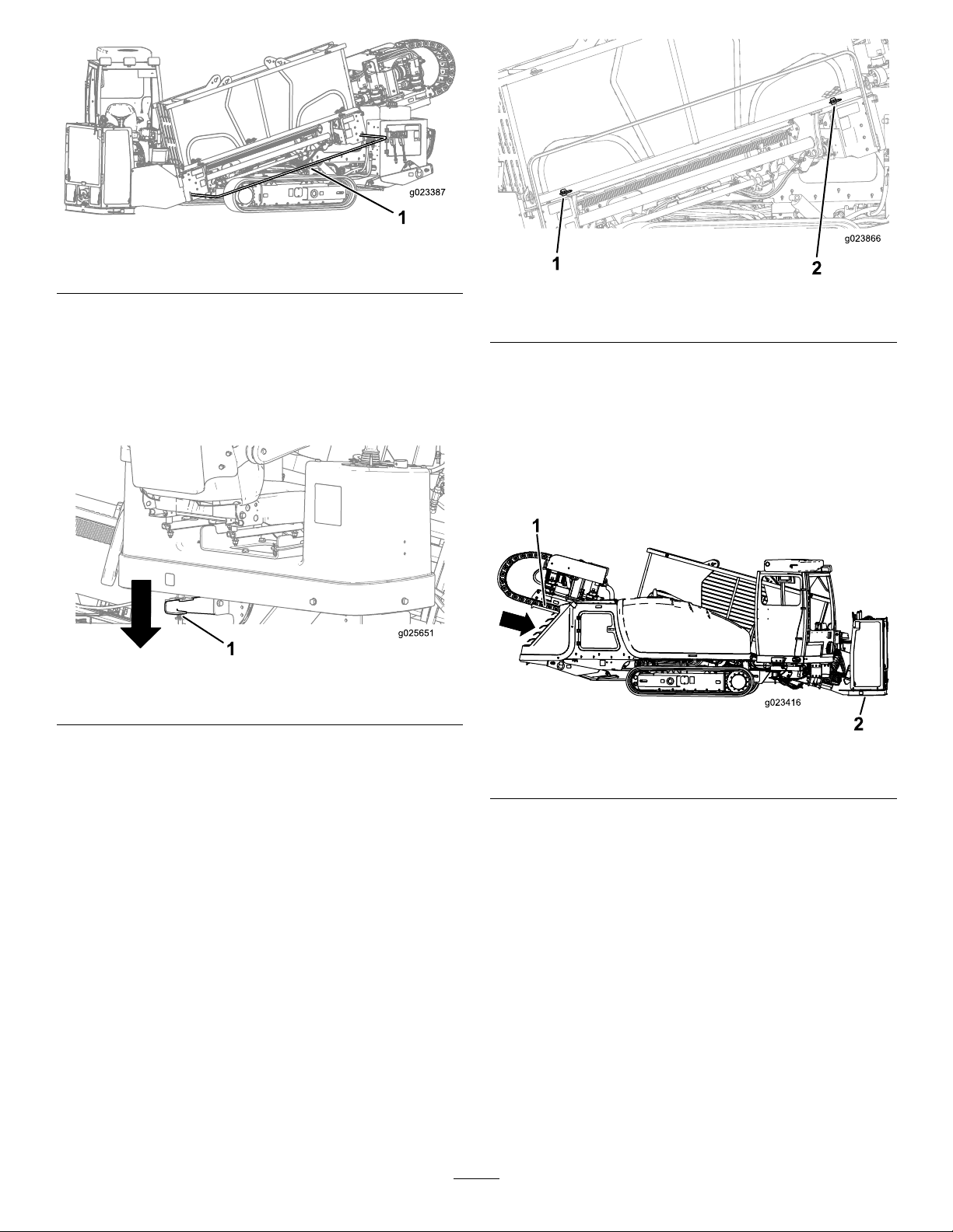
Figure70
1.Pedestriansafetybar(loweredpositionshown)
Figure72
5.Pushdownontherearplatformlatchsecuringthe
operatorplatform,andswingitouttothedesired
position,ensuringthatitlocksinplace(Figure71).
Note:Theoperatorplatformhas4positions:travel
(swungallthewayintothemachine),full-out,and2
intermediatepositions.
Figure71
1.Rearplatformlatch
6.Movetheoperatorstationtothedesiredangle,switch
theDrill/DriveswitchtotheDrillposition,andraise
thepipeelevators,sothatthepipeisrestingonthe
elevators;refertoStartingtheFirstPipe(page67).
Note:Removethefrontandrearpipe-holderpinsif
necessary(Figure72).
1.Frontpin2.Rearpin
7.Loadtherstpipeandinstallthesondeandthedrill
head;refertoStartingtheFirstPipe(page67).
8.Placethedrillheadonthedrillframe,andtakeapitch
readingusingthereceiver;refertotheTrackingSystem
Operator’sManual.
9.Lowerthethrustframe,tiltingthedrillframeuntilthe
platecontactstheground(Figure73).
Figure73
1.Thrustframe2.Stake-downplate
10.Lowertherearstabilizersuntiltheycontacttheground
rmly,oruntilthedesiredentryangleisachieved
(Figure74).
Note:Therearofthetracksshouldjuststarttolift
offtheground.
Note:Ifthegroundissoft,placetimberbelowthe
stabilizers,andlowerthestabilizers.
64
Page 65

g021835
1
2
3 4
ConnectingtoaDrilling-uidSource
Whendrillingandreaming,youpumpamixtureofbentonite
clay,water,andsometimesotheringredients,collectively
calleddrillinguidor“mud”,throughthepipeandintothe
bore.Thisdrillinguid,or“mud”,doesthefollowingfor
yourbore:
•Lubricatesthedrillhead
•Loosensthesoilintowhichthedrilliscutting
•Penetratesandbindsloosesoiltokeepitfromcollapsing
ontheborepipe.
Important:Donotoperatethedrilling-uidpump
withoutapressurizedsupplyofdrillinguid,ordamage
tothepumpingsystemwillresult.
Thespecicmixtureyouneedwillvarydependingonyour
soiltypeandtheoperationthatyouareperforming.Referto
yourmixingsystemOperator’sManualfordetails.
Figure74
1.Rearstabilizers
11.Pressthe2rightstakeleversintolowerandspinthe
rightstakeaugeruntilitseatsfully(Figure75).
Figure75
1.Left-stake-raise/lower
lever
2.Left-stake-spinlever
3.Right-stake-raise/lower
lever
4.Right-stake-spinlever
Conversely,forsomejobs(dependingonthesoiltypeand
distance),youcanpumpscreenedwaterfromanaturalwater
source,suchasalakeorriver,throughthedrillinsteadof
mixeddrillinguid.
•Toconnectthemachinetoamixingsystem,referto
SettinguptheMixingSystem(page65).
•Toconnectthemachinetoanaturalwatersource,referto
SettingupthePumptoUseaNaturalWaterSource(page
66).
SettinguptheMixingSystem
Setupyourmixingsystemnearthedirectionaldrilllocation,
preferablydownwind,sothatfumesfromthemixingsystem
enginewillnotbotheryouwhileyouaredrilling.Followthe
instructionsprovidedinthemixingsystemOperator’ sManual
forsettingitupandusingit.
Completethestepsfollowingtoconnecttheexithosefrom
themixingsystemtothedrilling-uidpumponthemachine:
1.Raisethecam-lockleversonthepump-inletcap,and
removethecap(Figure76).
12.Repeatstep11fortheleft-sidestake.
65
1.Cam-locklevers
Figure76
2.Pump-inletcap
Page 66

2.Insertthehosefromthemixingsystemoverthepump
inlet,andsecureitwiththecam-locklevers.
SettingupthePumptoUseaNaturalWaterSource
Tosetupapumptouseanaturalwatersource,youmust
ensurethatyouusetheY-screentolterallmaterialsother
thanwater.
1.Removethepump-inletcap(Figure77).
DeployingtheZap-alertSystem
TheZap-alertsystemisanelectricstrike-sensingdevice
onthemachinethattriggersastrobelightandanaudible
alarmwheneverthedrillbit,reamer,orstakebreaksintoan
energizedpowerline.Intheeventofanelectricstrike,the
machinewillbecomeenergized,settingoffthealarm.The
operator’splatformiselectricallyisolatedfromtherestof
themachinetoprotectyou.
DANGER
IftheZap-alertsystemactivateswhiledrilling,the
machine,exceptfortheoperatorplatform,will
becomeenergized.Ifyoustepofftheoperator
platformorifsomeonetouchesthemachineor
wetgroundnearthemachineorinthebore,you
ortheonewhotouchedthemachinecouldbe
electrocuted,causingseriousinjuryordeath.
•TesttheZap-alertsystembeforedrilling.
•Deploythegroundingstakebeforedrilling.
Ensurethatthestakeisfullyinsertedintomoist
soil.
Figure77
1.Pumpthreads3.Y-screen
2.Pump-inletcap
2.AligntheY-screenwiththethreadsonthepump
(Figure77).
3.RotateandtightentheY -screenontothepump.
4.AttachthehosetotheY-screen,andbeginpumping
fromthenaturalwatersource.
•IftheZap-alertistriggered:
–Stayintheseatanddonottouchtheground
oranyotherpartofthemachineuntilthe
powerhasbeenturnedoff.Donotpour
liquidsorurinatefromtheoperatorplatform
ontotheground.
–Stopdrilling,stopthedrilling-uidow,and
retractthedrilloutoftheground.
–Keepeveryoneawayfromthemachine,
wetgroundnearthemachineorrunning
fromthemachine,andanyopensourcesof
water/mudthatisintheboreandcontacting
thebrokenline.
–Contacttheutilitycompanytohavethe
powershutofftothebrokenline.Donot
resettheZap-alertsystemuntilthepower
hasbeenturnedoff.
1.Removethegroundingstakefromtheholderonthe
sideoftheoperatorplatform(Figure78).
66
Page 67

g021838
1
Figure78
1.Groundingstake
2.Movethestakedirectlyawayfromthemachine,
perpendiculartothedrillframe,anddriveitintothe
grounduntilthehandletouchestheground.
3.Ifthegroundisdrywhereyouputthestake,soakthe
groundwithwaterbeforeusingthemachinetoensure
goodelectricalcontact.
4.Lowertheelevatorstoloadapipeintothecam.
5.Rotatethecamwiththepipefacingtowardtheoperator
untilthecamstops.
6.Rotatethepipe-grippercamforwarduntilthepipeis
inthegrippers.
7.Gripthepipewiththepipegrippers.
8.Continuetorotatethepipe-grippercamtowardthe
operator,untilthepipeisalignedwiththedrillspindle.
9.Rotatethedrillspindleclockwise,andmovethe
carriageslowlyforwardtoinsertthespindleintothe
femaleendofthepipe(Figure80).
DrillingtheBore
StartingtheFirstPipe
1.Ensurethatallbystandersareawayfromthemachine
andthattheexit-sidelockoutisOn.
2.Movethedrivecarriagefullydownthedrillframeand
spraythespindlethreadswiththreadjointcompound,
thenreturnthedrivecarriagetotheupperendofthe
frame(Figure78).
Figure80
1.Drillspindle2.Pipe
10.Movethedrivecarriageslowlydowntheframe
untilthemalethreadsonthepipeareunderthe
thread-joint-compoundapplicator,andapply
thread-jointcompoundtothethreads.
11.Continuetorotatethedrillspindleclockwise,untilthe
malepipethreadisfullyseatedintothesondehousing
orleadbar.
12.Releaseandretractthepipe-grippercamtothehome
position.
Important:Ensurethatyoufullyretractthe
pipegripperandrotateitallthewayoutorthe
carriagemaycollidewiththegripper,damaging
themachine.
13.Raisethepipeelevator.
1.Drillspindle
Figure79
2.TJC-applicatornozzle
3.Rotatethecamuntilthecamautomaticallystopsatthe
rstrowofpipesinthepipeholder.
14.Retractthecamtothehomeposition(pastthefourth
rowofpipes).
67
Page 68

SettinguptheDrillHeadandthe
TrackingSystem
Thedrillheadconsistsof2parts,thedrillbitandthesonde
housing(Figure81).
Figure81
1.Sondehousing
2.Drillbit
Drillbitsvaryinsizeandtypetomeetthevarioussoil
conditionsthatyoumayneedtodrillthrough.Someofthe
possibilitiesareasfollows:
•Straightblade—Usedinawiderangeofmediumdensity
soils.
•Bentblade—Usedinmediumtosoftsoils.Thisbithas
anadded20degreebendtoincreasesteeringperformance
insoftsoils.
•Trianglepointblade—Useinhardandrockysoils.This
bithascarbideedgestoreducewear.
Alloftheabovebitscomeinvaryingwidths.Awiderblade
increasesyourabilitytosteerinsoftsoils.Anarrowerblade
movesthroughhardsoilsbetter.ContactyourAuthorized
ToroDealerforacompletelistofavailableblades.
Thesondesandreceiversareessentialtotracktheposition
ofthedrillheadthroughoutthedrillingoperation.The
sondehousingonthedrillheadopensuptoacceptthesonde
beaconwhichworkswiththereceivertotrackthelocation,
pitch,direction,headorientation,andmoreofthedrillhead.
RefertotheTrackingSystemOperator’sManualforinstructions
onusingthesystem.
Figure82
1.Sondehousing4.Coverholes
2.Bolts
3.Drillbit
5.Cover
3.Insertthesondebeaconwiththeforwardendtoward
thedrillbitintothesondehousing(Figure83).
Figure83
1.Sondehousing
2.Sondebeacon
3.Drillbit
4.Installthehousingcoverandsecureitwiththescrews
(Figure82).
Toinstallthesondebeaconintothesondehousingonthe
drillhead,completethefollowing:
1.Replacethebatteriesinthesondebeaconasdescribed
intheTrackingSystemOperator’sManual.
2.Loosenthescrewssecuringthehousingcovertothe
housingandremovethecover(Figure82).
68
Page 69

InstallingtheDrillHead
1.Usingtheexit-side-lockouttransmitter,activatethe
exit-sidelockouttodisablethethrustandrotationof
thecarriage.
5.Usingthelowerwrench(stationarywrench),clampthe
leadbar,andtightenthedrillspindletofull-seatthreads.
6.Doublecheckthedrillheadandbittoensurethatthe
uidportsarecleanandfreefromobstructions.
WARNING
Ifthedrillrotatesorextendswhileyouor
othersaremanuallyworkingonthedrillbitor
pipeinfrontofthemachine,theworkercould
getcaughtinthebitorpipe,causingserious
injury,amputation,ordeath.
•Activatetheexit-sidelockoutonthe
exit-side-lockouttransmitterbefore
approachingthedillbitorpipewhen
attachedtothemachine.Thiswilldisable
thedrillcarriage.
•Donotwearlooseclothingorjewelrywhen
workingonadrillbitorpipeattachedto
themachine.Tielonghairupandoutof
theway.
2.Placetheleadbarthroughthelowerwrench(stationary
wrench)asshowninFigure84.
Important:Donotclampthewrenchonthebody
ofapipe,oritmaydamagethepipe.Gripthe
pipesonthethickenedareanearthejoint.
7.Installthedrillheadontotheendoftheleadbaras
directedbythedrillheadmanufacturer,thenmove
awayfromthefrontofthemachine.
Important:Donotpullthedrillheadintothe
pipeguide,oryoumaydamagethemachineor
thedrillhead.
BoringtheEntryShaft
Therststepinboringistocreatetheentryshaft.Inthis
step,youpushandborethedrillbitandrstfewpipesinto
thegroundatananglefrom0to16degrees(withthetracks
atontheground)untilyoureachthedesireddepthof
installation.
Important:Drillandreaminaclockwiserotation.
Ifyouuseacounterclockwiserotation,thepipeswill
disconnectfromeachotherandmaybedisconnected
underground.
1.Whentheareaisclearofpeople,activatetheexit-side
lockoutusingtheexit-side-lockouttransmitter
(theOK-to-Drilllightonthecontrolpanelshould
illuminate);presstheexit-side-lockout,resetswitchon
thecontrolpanel.
Figure84
1.Drillpipe
2.Upperwrench
(makeup/breakout
wrench)
3.Handthreadtheleadbarontothedrillspindlepipe
threads,thenmoveawayfromthefrontofthemachine.
4.Whentheareaisclearofpeople,activatetheexit-side
lockoutusingtheexit-side-lockouttransmitter
(theOK-to-Drilllightonthecontrolpanelshould
illuminate);presstheexit-side-lockout,resetswitchon
thecontrolpanel.
3.Lowerwrench(stationary
wrench)
4.Leadbar
2.Turnonthedrilling-uid-pumpswitch,andallowthe
uidpressuretobuildto1,379to2,068kPa(200to
300psi).
3.Rotatethedrillheaduntilthebitisatthe6o’clock
position.
4.Movethecarriageforward,drivingthebitstraightinto
thegrounduntiltheentiredillhousingisunderground.
5.Continuepushingforward,andbeginrotatingthedrill
spindleclockwisetoinitiatethedrillingaction.
6.Drillforwarduntilthecarriagereachestheendofthe
frame,thenretractitabout6mm(1/4inch).
69
Page 70

AddingDrillPipes
SteeringtheDrillHead
1.Alignthepipejointinthewrenchassembly.
2.Closethelowerwrench(stationarywrench)ontothe
rstpipe.
Note:Thedrillinguidwillautomaticallyshutoff
whenyouactivatetheupperwrench(makeup/breakout
wrench).
3.Pullbackthecarriageapproximately12.7mm(0.5
inch).
Note:Thiswillallowthecarriagetooat,andwillnot
damagethepipethreads.
4.Rotatethedrillheadcounterclockwiseuntilthespindle
iscompletelyremovedfromthepipe.
5.Spraythespindlewiththreadjointcompound,then
returnthedrivecarriagetotheupperendoftheframe.
6.Rotatethepipe-grippercamtotheclosestrowofpipes
inthepipeholder.
7.Lowerapipeintothepipe-grippercam,andgripitin
place.
8.Rotatethepipegripperuntilthepipeiscenteredin
frontofthespindleonthedrivecarriage.
9.Rotatethedrillspindleclockwiseandmovethecarriage
slowlyforwardtoinsertthespindleintothefemaleend
ofthepipe(Figure80).
Note:Tightenthejointuntilthepipeisrotatingwith
thespindle.
Thedrillbitisshapedlikeawedge,angledfromonesideof
thebittotheother.Whenyoupushthebitthroughthesoil
withoutrotatingit,itwillveertowardthedirectionthewedge
ispointing.Whenyourotatethepipeanddrillhead,itbores
throughthesoilinastraightpath.
Figure85
1.Drillbit
Whendrilling,thereceiveroperatorfollowsthedrillheadasit
progresses.Thereceiverreceivessignalsfromthesondein
thedrillheadidentifyingitsposition,depth,pitch,direction,
transmittertemperature,andorientationinthesoil.The
remoteconsoleisascreenthatremainsnearyou(thedrill
operator)toshowyoutheinformationfromthereceiver
whiledrillingsothatyoucanmakesteeringdecisions.
Fordetailedinformationonusingthereceiverandremote
consoletoguidethedrillhead,refertotheOperator’ sManual
thatcamewithyourreceiver.
Important:Donotsteerthedrillheadmorethan20
cm(8inches)offcenterforevery3m(10ft)offorward
travel.Ifyousteermorethanthis,youwilldamagethe
drillpipes.
10.Movethedrivecarriageslowlydowntheframe
untilthemalethreadsonthepipeareunderthe
thread-joint-compoundapplicator,andapply
thread-jointcompoundtothethreads.
11.Rotatethedrillspindleclockwiseandmovethecarriage
slowlyforwardtoinsertthemaleendofthepipeinto
thefemaleendofthepreviouspipe.
Note:Tightenthejointuntilyoureachnomorethan
2,304N-m(1,700ft-lb).
12.Releaseandrotatethepipe-grippercamclockwiseto
thehomeposition.
Important:Ensurethatyoufullyrotatethe
pipe-grippercam,orthecarriagemaycollidewith
thegripper,damagingthemachine.
13.Rotatethemaincampastthefourthrowofpipeto
thehomeposition.
BoringtheHorizontalShaft
Aftercreatingtheentryshaft,yougraduallysteerthedrill
headupwhilepushingforward,followingtheplannedbore
path.Whenyoureachthedesireddepth,leveloutthedrill
headandborethehorizontalshaft,addingpipesasyougo.
Whileboring,paycloseattentiontotheinformationrelayed
backtoyoubythereceiveroperatoraboutthestatusand
locationofthedrillheadtoensurethatyouarefollowingthe
plannedpath.
Important:Whiledrilling,watchthesondetemperature.
Allsondeshaveamaximumtemperature,abovewhich
theywillbedamaged.Frictionbetweenthedrillhead
andthesoilwillcausethetemperaturetoraise.To
reducethetemperature,slowdown,decreaseforward
pressure,andincreasethedrilling-uidow.Ifthe
drillheadisenteringasoiltypeotherthanwhatitis
designedfor,thatcanalsoraisethetemperature.Assess
thesituationandpulloutthedrillheadandchangeit
ifnecessary.
Ifyourunintoanobstruction,dothefollowing:
1.Increasetheowofthedrillinguidforafewseconds
withoutdrilling,thenattempttocontinuedrilling
forward.
70
Page 71

Note:Thismayloosentheobstructionandallowyou
topushpastit.
2.Iftheobstructionpersists,tryoneormoreofthe
followingoptions:
•Iftheobstructionisinanareawhereyoucandig,
stopthedrillheadwiththeExitSideLockout
anddigdowntotheobstructiontoidentifyitand
removeitifpossible.
•Pullthedrillheadback15m(50ft)ormoreand
steerthedrillheadtotheside,markinganewdrill
patharoundtheobstacle.
Important:Donotsteerthedrillheadmore
than20cm(8inches)offcenterforevery3m
(10ft)offorwardtravel.Ifyousteermorethan
this,youwilldamagethedrillpipes.
•Iftheobstructionisactuallyachangeinsoiltype,
suchasazoneofrockysoil,pullthedrillheadall
thewaybackandchangetoadrillbitappropriate
fordrillingthroughthenewsoiltype.
BackreamingandPullback
Afterdrillingtheinitialbore,youattachareamertothe
pipe,whichisthenconnectedtoatheproductthatyouare
installing.Thereamerisdesignedtowidenthebore,packthe
walls,andlubricatethepassageoftheproductintothebore.
ThefollowingreamersareavailablefromyourAuthorized
ToroDealerinvarioussizestomeetyourneedsandsoil
conditions:
•Carbidestep-wingcutter—Usethisreamerinsandy
andmediumclaysoilconditionstomixthedrillinguid
withthesoil,makingamixturethatowseasilyaround
theproductbeingpulled.
•Castconepacker—Usethisreamerinsoilsthatpack
easily,suchassoftclay,peat,andloam,topackthesides
ofthebore,maintainingtheboreopening.
•Flutedreamer—Usethisreamerinhardclayandrocky
soils;itcombinesthefeaturesoftheother2reamers.
ConnectingtheReamerandProduct
ExitingtheGround
Asyouapproachtheendofthebore,steerthedrillheadto
theexitpoint,keepingthesteeringlimitsinmindasyoudo
so.Beforeexitingtheground,ensurethateveryoneisaway
fromtheexitpoint.Assoonasyoubreakthrough,stopthe
drilling-uidow .Extendthedrillforwarduntiltheentire
drillheadisoutoftheground.
WARNING
Ifthedrillrotatesorextendswhileyouorothersare
manuallyworkingonthedrillbitorpipeinfront
ofthemachine,theworkercouldgetcaughtinthe
bitorpipe,causingseriousinjury,amputation,or
death.
•Enabletheexit-sidelockoutonthe
exit-side-lockouttransmitterbeforeapproaching
thedillbitorpipewhenattachedtothemachine.
Thiswilldisablethedrillcarriage.
•Donotwearlooseclothingorjewelrywhen
workingonadrillbitorpipeattachedtothe
machine.Tielonghairupandoutoftheway .
1.Usingtheexit-side-lockouttransmitter,enabletheexit
sidelockout.
2.Removethedrillheadfromtheleadbar.
3.Doublecheckthereamertoensurethattheuidports
arecleanandfreefromobstructions.
4.Installthereamerandswivelontotheendofthelead
barasdirectedbythereamermanufacturer.
5.Connecttheproducttothereamerusinganappropriate
pullingconnection;refertoyourAuthorizedToro
Dealertoacquiretheappropriatepullertomeetyour
requirements.
71
Page 72

RemovingDrillPipes
g021841
1
2
1.Usingtheexit-side-lockouttransmitter,enabletheexit
sidelockout.
2.Installadrill-pipewiperaroundthepipeandintothe
retainingbracketonthefrontofthemachine.
Note:Thiswillremovemostofthedirtandmud
fromthepipeasyoupullitbackintothemachine,
keepingthemachineclean.ContactyourAuthorized
ToroDealertopurchasedrill-pipewipers.
12.Rotatethedrillspindlecounterclockwise,moving
rearwardslowlyuntilthepipesareseparated.
13.Movethedrillcarriagebackuntilthemale,pipethreads
justclearthefemaleendofthelowerpipe,thenclose
theupperwrench(makeup/breakoutwrench)ontothe
pipeend,butnotonthethreads.
14.Rotatethedrillspindlecounterclockwiseuntilthe
upper-pipejointisloosebutnotseparated.
15.Releasetheupperwrench(makeup/breakoutwrench).
16.Movethedrillcarriagebackuntilthepipeislinedup
withthepipeholder.
17.Rotatethedrillspindlecounterclockwise,moving
rearwardslowlyuntilthespindlefullyseparatesfrom
thepipe.
18.Rotatethepipe-gripperarmsuntilthepiperestsinside
thepipe-grippercam.
19.Rotatethepipecamtothedesiredrow.
Note:Filltheoutsiderowsrst.
20.Releasethepipegripper,andraisethepipeintothe
holderrowwiththepipeelevator.
Figure86
1.Drill-pipewiper2.Drillpipe
3.Disengagetheexit-sidelockoutandresetthesystem.
4.Beginrotatingthedrillspindleclockwiseandslowly
retractthedrivecarriagetopullthepipebackintothe
machine.
5.Whenthejointbetweenthepipesiscenteredbetween
the2wrenches,thedrivecarriagewillstop,andagreen
lightwillilluminatebelowthesprayvalve.
6.Closethelowerwrench(stationarywrench)ontothe
pipejoint.
Note:Thedrillinguidwillautomaticallyshutoff
whenyouclosethelowerwrench(stationarywrench).
7.Rotatethepipecamtothedrillframe,extend
pipe-gripperarmstothepipe,andgripthepipeto
supportit.
8.Closetheupperwrench(makeup/breakoutwrench)
ontothepipejoint.
9.Rotatetheupperwrench(makeup/breakoutwrench)
counterclockwiseuntilthejointisloosened.
21.Rotatethepipecampastthefourthrowofpipesto
thehomeposition.
Important:Ensurethatyoufullyretractthe
pipegripper,orthecarriagemaycollidewiththe
gripper,damagingthemachine.
22.Movethedrillspindledowntheframeunderthe
thread-joint-compoundapplicator,andspraythe
spindlewiththreadjointcompound.
23.Rotatethedrillspindleclockwise,andmovethe
carriageslowlyforwardtoinsertthespindleintothe
femaleendofthepipesecuredinthelowerwrench
(stationarywrench).Tightenthejointuntilyoureach
thefullmachinetorque.
24.Releasethewrenchandcontinuereaming/retraction
asneeded.
10.Releasetheupperwrench(makeup/breakoutwrench).
11.Pullbackthecarriageapproximately12.7mm(0.5
inch).
Note:Thiswillallowthecarriagetooat,andwillnot
damagethepipethreads.
72
Page 73

RemovingtheLastPipeandtheReamer
Important:Donotpullthedrillheadintothepipe
guide,oryoumaydamagethemachineorthedrillhead.
1.Usingtheexit-side-lockouttransmitter,enabletheexit
sidelockout.
2.Afterthereamerhasclearedtheground,ifyouhave
notalreadydoneso,disconnecttheproductbeing
installedfromthereamer.
3.Connectthedrillinguidpumptoasourceofclean
water.
4.Turnthepumpontoushcleanwaterthroughthe
pump,spindle,andreameruntilthewaterrunsclear.
5.Removeandstorethelastpipe;refertoRemovingDrill
Pipes(page72).
6.Leavetheleadbarclampedinthelowerwrench
(stationarywrench),butdonotconnectthedrillspindle
totheleadbar.
7.Removethereamerfromtheendoftheleadbaras
directedbythereamermanufacturer.
8.Releasethelowerwrench(stationarywrench)andpull
theleadbaroutofthepipeguide.
UsingtheTJCApplicator
AdjustingtheApplicatorNozzle
Youcanadjusttheapplicatornozzletospraythread-joint
compound(TJC)eitherinafan-shapedsprayorasastream.
•Forfan-shapedspray,turnthesprayvalveonthesideof
thenozzlehorizontal(Figure87).
•Forastream,turnthesprayvalveonthesideofthe
nozzlevertical(Figure87).
FinishingtheJob
Completethefollowingaftereachdayofuse:
•Connectthehandsprayguntothequickdisconnect
locatedattherearcompartment,andcleanthemachine
withcleanwater;refertoCleaningwiththeSpray-hose
Attachment(page113).
•Addgreasetothegreasettings;refertoGreasingthe
Machine(page82).
•Iftheairtemperatureisbelowfreezingorwillbebefore
thenextuse,refertoPreparingtheDrilling-uidSystem
forColdWeather(page110).
•Installthecontrolscovers;refertoOperator-controls
Covers(page24).
•Flushthedrillinguidoutofthedrilling-uidpumpwith
waterorantifreeze.
Important:Thedrilling-uidpumpmaybe
damagedifthedrilling-uiddriesupinthepump.
Figure87
1.Sprayvalve—fan-shaped
spray(horizontal)
2.Sprayvalve—stream
(vertical)
73
Page 74

AdjustingtheTJC-sprayVolume
FillingtheTJCApplicator
1.Loosenthejamnutontheadjustmentboltlocatedon
topoftheTJC-applicatorpiston(Figure88).
Figure88
1.Adjustmentbolt
2.Jamnut
3.TJC-applicatorpiston
2.Adjusttheboltsasfollows:
•Toincreasetheappliedvolumeofcompound,
threadtheboltout(up).
1.Stopthemachineandstoptheengine.
2.Openthestake-down-guarddoor.
3.Loosenthewingnutssecuringthecoverstrapstothe
machine(Figure89).
Figure89
1.TJC-applicatorpiston
2.Cover5.TJCbucket
3.Strap
4.Wingnut
•Todecreasetheappliedvolumeofcompound,
threadtheboltin(down).
3.Whenyouhaveattainedthedesiredapplicationvolume,
tightenthejamnuttosecuretheadjustment.
4.Rotatethecoverandpullthecoverstrapsoffthe
retainingbolts(Figure89).
5.Liftthecoverassemblyoffandoutoftheempty
thread-joint-compoundbucket(Figure89).
6.Replacetheemptybucketwithanewfullbucket.
7.Placetheplungerintothenewbucketandlowerthe
coverassemblyontothebucket(Figure89).
8.Slidethecoverstrapsovertheretainingbolts,and
rotatethecovertoseatthestrapsonthebolts(Figure
89).
9.Tightenthewingnuts.
74
Page 75

MovingaDisabledMachine
ReplacingthePipeHolder
Wheneverthemachineisstoppedandtheengineisnot
running,thehydrostaticbrakesautomaticallyengage.Donot
attempttotowthemachineifitcannotmoveunderitsown
power.Ifpossible,repairthemachineatthesite.Ifthisisnot
possible,useacraneandaspreaderbartoliftthemachine
ontoatrailer,usingtheliftpointsshowninFigure90.
Figure90
Repeatliftpointsonotherside
1.Ensurethatthe2upperpinsandthe2lowerpins
areinstalledtosecurethepipeinsidethepipeholder
(Figure91).
Figure91
1.Upperpins2.Lowerpins
2.Removethelower,outerpinsonthepipeholder
(Figure92).
1.Liftpoint2.Spreaderbar
Figure92
1.Frontpin2.Rearpin
3.Withahoistcapableoflifting2,260kg(5,000lb),
removethepipeholder.
75
Page 76
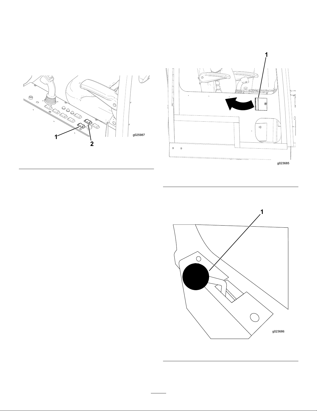
PositioningtheCab(Model
OpeningtheDoor(Modelwith
withCabonly)
PositioningtheCabforDrilling
Operation
1.Pushbackontheswingrockerswitch(untilthecab
stops)toswingthecabtothedrillposition(Figure93).
Figure93
1.Swingrockerswitch
Important:Ensurethatyouswingthecabout
completelybeforerotating,oryoumaycontactthe
machine,causingdamagetothecab.
2.Pushbackontherotaterockerswitchtorotatethecab
tothedesireddrillposition(Figure93).
2.Rotaterockerswitch
Cabonly)
Openthedoorfromtheoutsidebypullingonthehandle,and
swingthedoortotheleft(Figure94).
Figure94
1.Doorhandle
Openthedoorfromtheinsidebypullingtheknobbackward
andpushingthedoortotheoutside(Figure95).
PositioningtheCabintoTransport
Mode
1.Pushforwardontherotaterockerswitch(untilthe
cabstops)torotatethecabtothetransportposition
(Figure93).
Important:Ensurethatyoucompletelyrotatethe
cabtothetransportposition(clockwise)before
swining,oryoumaycontactthemachine,causing
damagetothecab.
2.Pushforwardontheswingrockerswitch(untilthe
cabstops)toswingthecabtothetransportposition
(Figure93).
Figure95
1.Doorknob
76
Page 77

OperatingtheAirConditioning
OperatingtheWindshield
andHeating(ModelwithCab
only)
AirConditioningtheCab
1.Pushtheair-conditioningswitchtotherighttoturnthe
airconditioningtotheOnposition(Figure96).
Wipers(ModelwithCabonly)
ChangingtheWindshield-wiperSpeed
Turnthewindshield-wiperknob(Figure97)totheright
increasethespeedofthewindshieldwipers,orturntheknob
tothelefttodecreasethespeed.
Figure97
1.Windshield-wiperknob
Figure96
1.Cool/Coldtemperature
2.Air-conditioningswitchOff
position
3.Air-conditioningswitch8.Fan-speedknob
4.Air-conditionswitchOn
position
5.Warm/Hottemperature
2.Opentheventstoincreaseordecreasetheairow .
3.Turnthetemperatureknobtotheleftuntilyoureach
thedesiredtemperature(Figure96).
4.Turnthefan-speedknowtoeitherlow ,medium,or
high(Figure96).
6.Temperatureknob
7.Fanspeed(low ,medium,
orhigh)
9.FanOffposition
HeatingtheCab
1.Pushtheair-conditioningswitchtothelefttoturnthe
airconditioningtotheOffposition(Figure96).
2.Opentheventstoincreaseordecreasetheairow .
3.Turnthetemperatureknobtotherightuntilyoureach
thedesiredtemperature(Figure96).
DispersingtheWindshield-washer
Fluid
Pushdownonthewindshield-wiperknob(Figure97)to
dispersethedesiredamountofwindshieldwasheruid.
4.Turnthefan-speedknowtoeitherlow ,medium,or
high(Figure96).
77
Page 78

Maintenance
Note:Determinetheleftandrightsidesofthemachinefromthenormaloperatingposition.
RecommendedMaintenanceSchedule(s)
MaintenanceService
Interval
Aftertherst100hours
Aftertherst250hours
Beforeeachuseordaily
Every50hours
MaintenanceProcedure
•Checkthestakedownplanetary-driveoillevel(Also,checkifexternalleakage
isobserved).
•Checktherotarymotorplanetary-driveoillevel(Also,checkifexternalleakage
isobserved).
•Checkthethrustmotorplanetary-driveoil.
•Checkthegearboxdriveoil.
•Changethegearbox-driveoil.
•Adjustthevalveclearance.
•Changetheplanetary-driveoil.
•Checkthefuellevel.
•Greasethemachine.(Greaseimmediatelyaftereverywashing).
•Checkthecrankcase-venttubeandcleanitifnecessary .
•Checktheindicatoronthedisplayscreenforarestrictedairlter.
•Checktheengineoillevel.
•Checkthetracktension.
•Checkthecoolantlevelintheradiator.
•Checkthehydraulicuidlevel.
•Checkthedrilling-uidpumpoillevel.
•Cleanthemachinewiththespray-hoseattachment.
•Checkandcleanthedustvalve.
•Removeaircleanercoverandcleanoutdebris.Donotremovethelter.
•Checkthefuel-waterseparatorforwaterandsediment.
•Checkthebatterycondition.
•Checkthetracksrotarymotorplanetary-driveoillevel(Also,checkifexternal
leakageisobserved).
Every250hours
Every300hours
Every500hours
Every800hours
•Cleanorreplacetheair-cleanerlter.
•Changetheengineoillter .
•Changetheengineoil.
•Replacetheprimaryandsecondaryfuellters.
•Checktheconditionoftheengine-drivebelt.
•Checktheconditionofthecoolantsystemcomponents.Cleandirtanddebrisfrom
themandrepairorreplacethecomponentsasnecessary.
•Inspectthefuellinesandconnections.
•Checkthestakedownplanetary-driveoillevel(Also,checkifexternalleakage
isobserved).
•Checktherotarymotorplanetary-driveoillevel(Also,checkifexternalleakage
isobserved).
•Checkthethrustmotorplanetary-driveoil(oryearly,whichevercomesrst).
•Checkthegearboxdriveoil(oryearly,whichevercomesrst).
•Changethegearbox-driveoil(oryearly,whichevercomesrst).
•Changethehydrostatic-chargelter.
•Changethedrilling-uidpumpoil.
•Changetheplanetary-driveoil(oryearly,whichevercomesrst).
78
Page 79

MaintenanceService
Every1,000hours
Interval
MaintenanceProcedure
•Drainandcleanthefueltank.
•Checktheconcentrationofthecoolantbeforethewinterseason.
•Cleanthecoolingsystem.(Cleanthecoolingsystemifthecoolantbecomesdirtyor
rustcolored.)
•Checkthetensionontheenginedrivebelt.
•Changethehydraulicuid.
•Changethehigh-pressurehydrauliclter(andasneededpertheserviceindicator).
•Changethehydraulic-returnlter(andasneededpertheserviceindicator).
Every2,000hours
Yearlyorbeforestorage
Every2years
Important:RefertoyourEngineOperator'sManualforadditionalmaintenanceprocedures.
•Adjustthevalveclearance.
•T ouchupchippedpaint.
•Replacemovinghoses.
CAUTION
Ifyouleavethekeyintheignitionswitch,someonecouldaccidentlystarttheengineandseriouslyinjure
youorotherbystanders.
Removethekeyfromtheignitionbeforeyoudoanymaintenance.
WARNING
Improperlyservicingorrepairingthemachinemaycauseinjuryordeath.
Ifyoudonotunderstandtheserviceproceduresforthismachine,contactyourdealerorseetheservice
manualforthismachine.
WARNING
Raisedequipmentonthemachinewithoutanoperatormaycauseinjuryordeath.
Beforeyouleavetheoperator’scompartment,supportorlowertheequipmentandstoptheengine.
WARNING
Replaceallcoversandguardsafteryouserviceorcleanthemachine.Donotoperatethemachinewithout
thecoversorguardsinplace.
79
Page 80

Premaintenance
Procedures
OpeningtheFrontHood
1.Parkthemachineonalevelsurface,stoptheengine,
andremovetheignitionkey.
2.LiftuponthelatchasshowninFigure98.
Note:Ensurethatthekeyisintheopen(horizontal)
positionasshowninFigure98.
Figure100
1.Hoodhandle
OpeningtheRear-accessDoor
1.Parkthemachineonalevelsurface,stoptheengine,
andremovetheignitionkey.
Figure98
1.Keyintheopen
(horizontal)position
3.PulluponthehoodlatchasshowninFigure99.
2.Hoodlatch
2.Pushontheleftsideofthepanelhandle,andpullthe
panelopenwhenthehandleisreleased(Figure101).
Figure101
1.Rear-accessdoorhandle
Figure99
1.Hoodlatch
4.Keepthehoodlatch(Figure99)pulledup,andliftup
onthehandleasshowninFigure100.
80
Page 81

UsingtheCylinderLock
WARNING
Thethrustframemaylowerwhenitisintheraised
position,causingseriousinjuryordeath.
Installthecylinderlockbeforeperforming
maintenancethatrequiresthethrustframetobe
raised.
RemovingandStoringtheCylinder
Lock
1.Starttheengine.
2.Lowerthethrustframetothefullyloweredposition.
3.Stoptheengine.
4.Removethecotterpinandtheclevispinthatsecurethe
cylinderlock(Figure102).
5.Removethecylinderlock.
InstallingtheCylinderLock
1.Starttheengine.
2.Lowerthethrustframetothefully-loweredposition.
3.Stoptheengine.
4.Positionthecylinderlockoverthecylinderrod(Figure
102).
5.Securethecylinderlockwiththecotterpinandclevis
pin(Figure102).
6.TurntheenginetotheOnposition,andraisethethrust
frameuntilitrestsonthecylinderlock.
6.TurntheenginetotheOnposition,andraisethethrust
frame.
7.Storethecylinderlockattherearofthepipeholder
(Figure103).
Figure103
1.Locationbehindtherearofthepipeholder
Figure102
1.Cotterpin4.Clevispin
2.Cylinderlock5.Liftcylinder
3.Liftcylinderrod
81
Page 82

Lubrication
GreasingtheMachine
ServiceInterval:Beforeeachuseordaily(Grease
immediatelyaftereverywashing).
Greasetype:General-purposegrease.
1.Parkthemachineonalevelsurface,stoptheengine,
andremovetheignitionkey.
2.Cleanthegreasettingswitharag.
3.Connectagreaseguntoeachtting.
4.Pumpgreaseintothettingsuntilgreasebeginsto
oozeoutofthebearings(approximately3pumps).
5.Wipeupanyexcessgrease.
Figure106
Frontelevatorassembly(topview)
Figure104
Cylinderassembly(viewfromundermachine,near
stabilizerfoot)
Figure105
Trackframe(repeatonotherside)
Figure107
Rearelevatorassembly(topview)
Figure108
Frontpipe-loadercamarea(6ttings)
82
Page 83
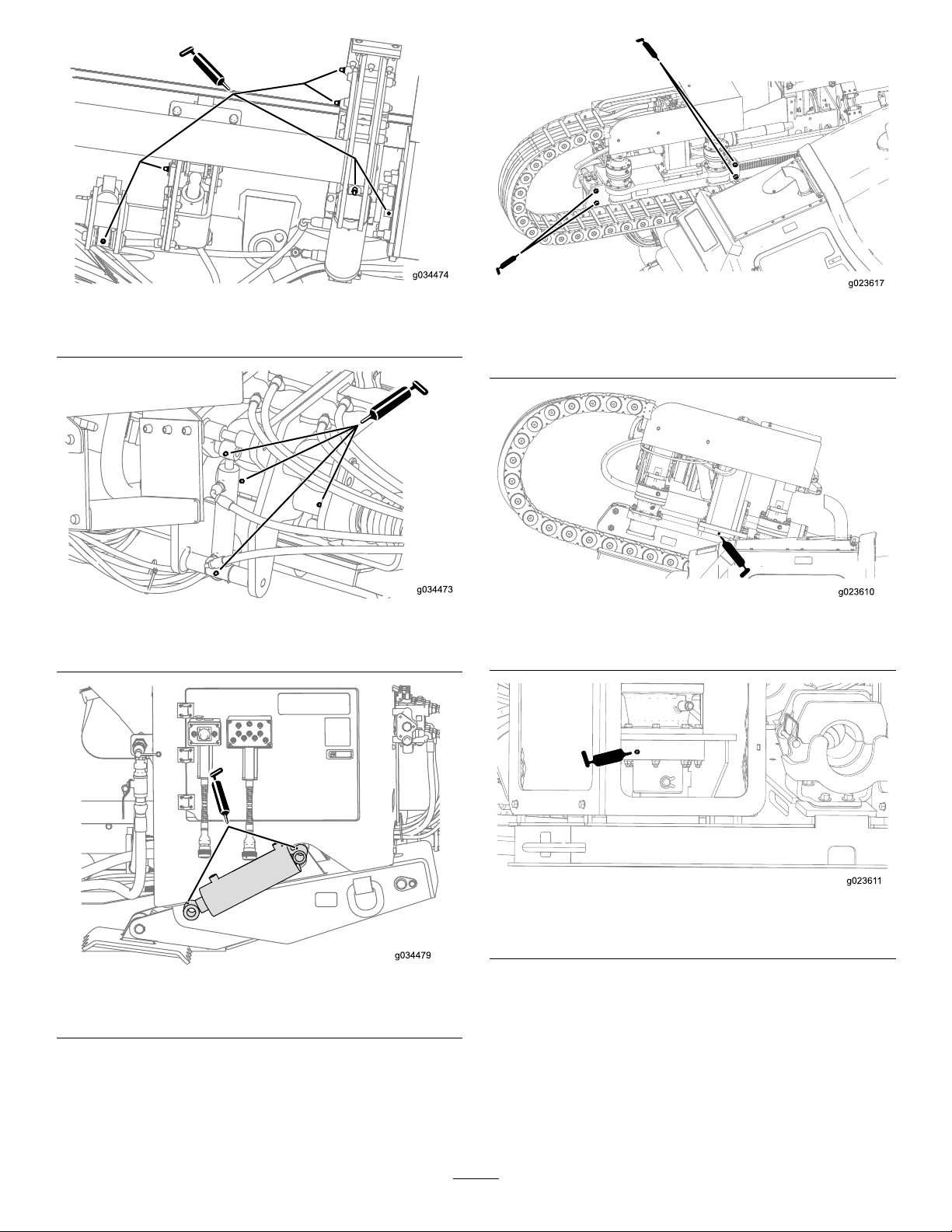
Figure109
Rearpipe-loadercamarea(6ttings)
Figure112
Carriage-rollerbearings(operator’ssideshown;repeaton
otherside)
Figure110
Hydrauliccylinderandwrenchassembly
Figure111
Stabilizercylinderandfoot(repeatonotherside)
Figure113
Gearboxoat(operator’ssideshown;repeatonotherside)
Figure114
Stakedownshaft(leftsideshown;repeatonrightside)
83
Page 84

EngineMaintenance
1
ESC
2
3
4
5
6
7
8
OK
6
12
18
24
30
n/min
x 100
G021619
1
CleaningtheCrankcase-vent
Tube
ServiceInterval:Beforeeachuseordaily—Checkthe
crankcase-venttubeandcleanitif
necessary.
1.Parkthemachineonalevelsurface,stoptheengine,
andremovetheignitionkey.
2.Openthefronthood.
3.Gentlypullthecrankcase-venttubeout(Figure115).
4.Cleantheendofthecrankcase-venttube(Figure115).
itisnecessaryonlyincreasesthechanceofdirtentering
theenginewhenthelterisremoved.
•Besurethatthecoverisseatedcorrectlyandsealswith
theair-cleanerbody.
CheckingtheAir-cleanerIndicator
ServiceInterval:Beforeeachuseordaily
1.Starttheengine.
2.Checktherestricted,air-cleanerindicatoronthedisplay
screenasshowninFigure116.
Figure115
1.Crankcaseventtube
ServicingtheAir-cleaning
System
Important:Donotremovetheelementsfromthe
machinetocheckfordirtylters;usethefollowing
procedureinstead.
Important:Donotreplacetheoldair-cleanerlterwith
alterthatismorethan5yearsold;checkthedateof
manufactureontheendcapoftheelement.
Note:Everytimeyouservicetheair-cleanersystem,ensure
thatallhoseconnectionsandangesareairtight.Replace
alldamagedparts.
•Checktheair-cleanerbodyfordamagewhichcouldcause
anairleak.Replaceitifitisdamaged.Checkthewhole
intakesystemforleaks,damageorloosehoseclamps.
Also,inspecttherubberintakehoseconnectionsattheair
cleanerandtheturbotomakesurethattheconnections
arecomplete.
•Servicetheair-cleanerlteronlywhen“CheckAirFilter”
isdisplayedonthescreen.Changingtheairlterbefore
Figure116
1.Restrictedair-cleanerindicator
3.Replacetheair-lterelement(s)asfollows:
A.Replacetheprimary,air-cleanerlter;referto
ServicingtheAir-cleanerFilter(page86).
B.Repeatsteps1and2;iftherestrictedair-cleaner
indicatorisstillshownonthedisplayscreen,
replacethesecondary,air-cleanerlter;referto
ServicingtheAir-cleanerFilter(page86).
84
Page 85

CleaningtheDustValve
ServiceInterval:Every50hours
1.Parkthemachineonalevelsurface,stoptheengine,
andremovetheignitionkey.
2.Opentherear-accessdoor.
3.Squeezethesidesofthedustvalveontheair-cleaner
covertoreleaseanycollectedwater,dust,ordirtfrom
thevalve.(Figure117).
Note:Ensurethattherearenoobstructionsinside
thedustvalve.
Figure118
1.Air-cleanercoverlatches
6.Pulltheair-cleanercoverawayfromthelterhousing
andremovethecover.
7.Cleananydebrisfrominsidethecover.
Important:If“CheckAirFilter”isnotdisplayed
onthescreen,donotremovetheairlter.
Figure117
1.Dustvalve2.Air-cleanercover
ServicingtheAir-cleanerCover
ServiceInterval:Every50hours—Removeaircleanercover
andcleanoutdebris.Donotremovethe
lter.
RemovingtheAir-cleanerCover
1.Parkthemachineonalevelsurface,stoptheengine,
andremovetheignitionkey.
2.Opentherear-accessdoor.
3.Cleantheoutsideoftheair-cleanercanisterwitha
clean,dampcloth.
4.Checktheair-cleanercoverfordamagewhichcould
causeanairleak.Replaceadamagedair-cleanerbody.
InstallingtheAir-cleanerCover
1.Parkthemachineonalevelsurface,stoptheengine,
andremovetheignitionkey.
2.Alignthedustcapontheaircleanerltercover.
3.Aligntheair-cleanercoverwiththelterhousing.
4.Placeair-cleanercoverinwarduntilitisfullyseated,
andsecureitwiththelatches(Figure118).
Important:Servicetheair-cleanerlteronlywhen
“CheckAirFilter”isdisplayedonthescreen.
Changingtheairlterbeforeitisnecessaryonly
increasesthechanceofdirtenteringtheengine
whenthelterisremoved.
5.Pullthe4latchesfortheair-cleanercoveroutward
(Figure118).
85
Page 86

ServicingtheAir-cleanerFilter
°C°F-40
-30 -20 -10 0 10 20 30 40 50
-40 -22 -4 14 32 50 68 86 104 122
All Seasons
Winter Conditions
Arctic Conditions
°C°F-40
-30 -20 -10 0 10 20 30 40 50
-40 -22 -4 14 32 50 68 86 104 122
15W -40
10W -30
5W-30
G022415
ServiceInterval:Every250hours
Replacetheltersonlywhenthe“CheckAirFilter”
indicatorappearsonthedisplayscreen;referto
CheckingtheAir-cleanerIndicator(page84).
Note:ContactyourAuthorizedT oroDealertoorder
replacementlters.
6.Insertthenewprimarylterbyapplyingpressuretothe
outerrimoftheltertoseatitintheair-cleanercover.
7.Removetherubberoutletvalvefromthecover,clean
thecavity,andreplacetheoutletvalve;refertoCleaning
theDustValve(page85).
8.Installthecover;refertoInstallingtheAir-cleaner
Cover(page85).
1.Parkthemachineonalevelsurface,stoptheengine,
andremovetheignitionkey.
2.Opentherear-accessdoor.
3.Beforeremovingthelter,cleanoutalldebrisfromthe
insideofthelterbodyusinglow-pressureairat275
kPa(40psi).
Important:Avoidusinghighpressureairwhich
couldforcedirtthroughthelterintotheintake
tract.Thiscleaningprocesspreventsdebrisfrom
migratingintotheintakewhentheprimarylter
isremoved.
4.Usingtheair-lterhandles,removetheprimarylter
fromtheair-cleanercover(Figure119).
Important:Donotcleantheusedlter.
ServicingtheEngineOiland
Filter
Theengineisshippedwithoilinthecrankcase;however,
checktheoillevelbeforeandafteryourststarttheengine.
Crankcasecapacity:7.5L(7.9USqt)withthelter.
Useonlyhigh-qualitylowashSAE15W-40heavy-dutyengine
oilwithanAPIclassicationofCJ-4(ACEAE9)orhigher.
WhilelowashSAE15W-40oilwithanAPIclassicationof
CJ-4(ACEAE9)orhigherisrecommendedformostclimates,
refertoFigure120foroilviscosityrecommendationsfor
extremeclimates.
1.Topofprimarylter3.Bottomofprimarylter
2.Air-lterhandles4.Air-ltercover
Figure119
5.Inspectthenewlterforshippingdamage,checking
thesealingendofthelterandthebody.
Note:Donotuseadamagedelement.
Figure120
Note:Limiteduseoflow-viscosityoilssuchasSAE10W-30
withanAPIclassicationofCJ-4(ACEAE9)orhigher
canbeusedforeasierstartingandprovidingsufcientoil
owatambienttemperaturesbelow-5°C(23°F).However,
continuoususeoflowviscosityoilcandecreaseenginelife
becauseofwear(Figure120).
ToroPremiumEngineOilisavailablefromanAuthorized
ToroServiceDealerineither15W -40or10W-30viscosity
withAPIclassicationCJ-4(ACEAE9)orhigher.Seethe
partscatalogforpartnumbers.
86
Page 87

CheckingtheEngine-oilLevel
ServiceInterval:Beforeeachuseordaily—Checktheengine
oillevel.
B.Installtheoil-llcapandthedipstick.
ChangingtheEngine-oilFilter
1.Parkthemachineonalevelsurface,stoptheengine,
andremovetheignitionkey.
2.Openthefronthood.
3.Removethedipstick(Figure121),andwipeitclean.
Figure121
Operator’sside
1.Dipstick
ServiceInterval:Every250hours
1.Parkthemachineonalevelsurface,stoptheengine,
andremovetheignitionkey.
2.Openthefronthood.
3.Alignadrainpanorseveralragsundertheoillterand
theoil-lteradapter(Figure123).
Figure123
1.Oillter2.Oil-lteradapter
4.Insertthedipstickintotheoillltube,pullthedipstick
outagain,andreadtheoillevelonthedipstick.
Note:Theoillevelonthedipstickshouldbeatthe
HighmarkorbetweentheLowandHighmarks.If
theoilisbelowtheLowmark,completethefollowing
procedure:
A.Removethellcap(Figure122)andaddoiluntil
thelevelreachestheHighmark.Donotoverll.
Important:Useanoilcanisterwitha
bendablehoseorafunneltollthemachine
withoil.
4.Rotatetheoilltercounterclockwiseandremovethe
oillter(Figure123).
Note:Discardtheoillter.
5.Usingacleanrag,wipecleanthesurfaceoftheoil-lter
adapterwheretheoillterseatswithacleanrag.
6.Fillthenewoillterwiththespeciedengineoil.
7.Applyathinlayerofthespeciedengineoiltotheseal
oftheoillter.
8.Aligntheoilltertotheoil-lteradapter,androtate
itclockwiseuntilthesealoftheoilltercontactsthe
oil-lteradapter(Figure123).
Important:Donotuseanoillterstrapwrench
toinstallthenewoillter.Thewrenchcandent
anoillterandthereforecausealeak.
9.Handtightentheoillteranadditional1/2turn
(Figure123).
10.Removetheoilpanorragsyouplacedinstep3and
disposeoftheusedoilaccordingtolocalcodes.
1.Oil-llcap
Figure122
87
Page 88

ChangingtheEngineOil
ServiceInterval:Every250hours
1.Parkthemachineonalevelsurface,stoptheengine,
andremovetheignitionkey.
WARNING
Allowtheengineandoiltocoolbefore
drainingtheoil.Hotoilmaycauseserious
injury.
2.Ensurethatthedrainhose(Figure124)iscarefully
pulledupandtheendofthehoseisplacedinadrain
pan.
Figure124
1.Drainhose2.Drainvalve
Figure125
1.Fillerneck3.Funnel
2.Oil-llcap
Note:Useafunnelwithaexible,attachedhoseto
directtheengineoilintotheengine.
9.Fillthecrankcasewithapproximately7.5L(7.9US
qt)ofthespeciedengineoil;refertoServicingthe
EngineOilandFilter(page86).
10.Installtheoil-llcap.
11.Starttheengine,runitatidleforabout2minutes,and
checkforoilleaks.
12.Stoptheengineandremovethekey.
13.Waitfor2or3minutesandchecktheoillevel;referto
CheckingtheEngine-oilLevel(page87).
AdjustingtheValveClearance
ServiceInterval:Aftertherst250hours
Every2,000hours
3.Openthedrainvalve(Figure124).
4.Draintheoilintothedrainpan.
5.Whentheoilstops,closethedrainvalve(Figure124).
6.Placethedrainhosebackintotheoriginalposition
(Figure124).
7.Changetheengineoillter;refertoChangingthe
Engine-oilFilter(page87).
8.Removetheoil-llcapfromthellerneckbypulling
thecapupward.
Refertotheengineowner’ smanual,whichisincludedwith
themachine,fortheadjustmentprocedure.
Ifyoucannotadjustthevalveclearance,contactyour
AuthorizedToroServiceDealer.
88
Page 89

FuelSystem
Maintenance
Note:Ifthefuel-waterseparatorhasanywateror
sediment,alsodrainthewaterandsedimentfrom
thefueltank;refertoDrainingWaterfromtheFuel
Tank(page89).
DANGER
Undercertainconditions,dieselfuelandfuel
vaporsarehighlyammableandexplosive.Are
orexplosionfromfuelcanburnyouandothersand
cancausepropertydamage.
•Useafunnelandllthefueltankoutdoors,in
anopenarea,whentheengineisoffandcold.
Wipeupanyfuelthatspills.
•Donotllthefueltankcompletelyfull.Addfuel
tothefueltankuntilthelevelis25mm(1inch)
belowthebottomofthellerneck.Thisempty
spaceinthetankallowsthefueltoexpand.
•Neversmokewhenhandlingfuel,andstayaway
fromanopenameorwherefuelfumesmaybe
ignitedbyaspark.
•Storefuelinaclean,safety-approvedcontainer
andkeepthecapinplace.
DrainingWaterfromtheFuel
Filter
5.Whencleanfuelappears,rotatethedrainvalve
clockwiseuntilitisclosed.
Note:Donotovertightenthedrainvalve.
6.Primethefuelsystem;refertoPrimingtheFuel
System(page90).
DrainingWaterfromtheFuel
Tank
1.Parkthemachineonalevelsurface,stoptheengine,
andremovetheignitionkey.
2.Placeadrainpanunderthedrainpluginthefueltank.
3.Loosenthedrainpluguntilthewaterandsediment
drainout(Figure127).
ServiceInterval:Every50hours—Checkthefuel-water
separatorforwaterandsediment.
1.Parkthemachineonalevelsurface,stoptheengine,
andremovetheignitionkey.
2.Openthefronthood.
3.Alignadrainpanundertheprimaryfuellter(Figure
126).
Figure126
1.Drainvalve
2.Primaryfuellter
Figure127
1.Drain-plughole3.Drainpan
2.Drainplug4.Fueltank
4.Cleanthethreadsonthedrainplugandapply3layers
ofPTFEsealingtape.
5.CleantheO-ringifitcomesout.
6.Whencleanfuelappears,installtheO-ringanddrain
plug,andtightentheplugsecurely .
7.Checkthefuel-tankdrainplugforleaks.
4.Rotatethedrainvalveatthebottomoftheprimary
fuellter2or3turnscounterclockwise,anddrainany
waterandsedimentfromthefuellter(Figure126).
89
Page 90

PrimingtheFuelSystem
WARNING
Note:Primethefuelsystemwheneveranyofthefollowing
occurs:
•Youdrainedwaterfromthefuellter.
•Youreplacedthefuellter.
•Yourantheengineuntilthefueltankisemptyordrained
thefueltank.
1.Parkthemachineonalevelsurface,stoptheengine,
andremovetheignitionkey.
2.Openthefronthood.
3.Ensurethattheengineandtheexhaustsystemarecool.
4.Ensurethatthefueltankisatleast1/4full.
5.Rotatethebattery-disconnectswitchclockwisetothe
Onposition.
6.Locatetheprimingbuttononthetopofthelter
adapterfortheprimaryfuellter(Figure128).
Thefuelsystemisunderhighpressure.
Bleedingthesystemwithoutproper
precautionsandtrainingcouldresultininjury
toyoufrominjecteduidorreorexplosion.
Readtheengineowner’smanualforthe
properbleedingprocedureorcontactyour
AuthorizedT oroDealer.
ReplacingtheFuelFilters
ServiceInterval:Every250hours—Replacetheprimary
andsecondaryfuellters.
ReplacingthePrimaryFuelFilter
1.Parkthemachineonalevelsurface,stoptheengine,
andremovetheignitionkey.
2.Openthefronthood;refertoOpeningtheFront
Hood(page80).
3.Placecleanragsundertheprimaryfuellter(Figure
128).
Figure128
1.Primaryfuel-lteradapter
7.Pressdownandreleasetheprimingbuttonrepeatedly
untilyoufeelresistancewhenpressingthepriming
button(Figure128).
8.Iftheenginedoesnotstartafterprimingthefuel
systemandmakingseveralattemptstostarttheengine,
bleedthehigh-pressurefuellines;refertoyourengine
owner’smanualorcontactyourAuthorizedToro
ServiceDealer.
2.Primingbutton
4.Loosenthehoseclampsandseparatetheprimaryfuel
lterfromthefuelhoses(Figure128).
Note:Donotremovethehoseclampsfromthehoses.
Note:Discardthefuellter.
5.Alignthenewprimaryfuelltertothehoseswiththe
arrowprintedonthelterpointingforward.
6.Slipthehosesoverthehosettingoftheprimaryfuel
lter,andtightenthehoseclamps(Figure128).
7.Replacethesecondaryfuellter;refertoReplacingthe
SecondaryFuelFilter(page91).
90
Page 91

ReplacingtheSecondaryFuelFilter
1.Parkthemachineonalevelsurface,stoptheengine,
andremovetheignitionkey.
2.Openthefronthood;refertoOpeningtheFront
Hood(page80).
3.Alignadrainpanorseveralragsunderthesecondary
fuellterandthefuel-lteradapter(Figure129).
Figure129
1.Secondaryfuellter
2.Filteradapter
CheckingtheFuelLinesand
Connections
ServiceInterval:Every500hours/Yearly(whichever
comesrst)—Inspectthefuellinesand
connections.
Inspectthefuellinesandconnectionsfordeterioration,
damage,orlooseconnections.
DrainingandCleaningtheFuel
Tank
ServiceInterval:Every1,000hours/Yearly(whichever
comesrst)—Drainandcleanthefuel
tank.
Drainandcleanthetankifthefuelsystembecomes
contaminatedorifthemachinewillbestoredforanextended
periodoftime.Usecleanfueltoushoutthetank.Referto
DrainingW aterfromtheFuelTank(page89)fordraining
instructions.
Note:Performthisprocedurewhenthefuellevelislow ,to
avoiddrainingalargevolumeoffuel.
4.Rotatethefuelltercounterclockwiseandremovethe
fuellter(Figure129).
Note:Discardthefuellter.
5.Usingacleanrag,wipecleanthesurfaceofthe
fuel-lteradapterwherethefuellterseatswithaclean
rag.
6.Fillthenewfuellterwiththespeciedfuel.
7.Alignthefuelltertothefuel-lteradapter,androtate
itclockwiseuntilthesealofthefuelltercontactsthe
fuel-lteradapter(Figure129).
Important:Donotuseafuellterstrapwrench
toinstallthenewoillter.Thewrenchcandenta
fuellterandthereforecausealeak.
8.Handtightenthefuellterandadditional1/2turn
(Figure129).
9.Removethedrainpanorragsyouplacedinstep3and
disposeoftheusedfuelaccordingtolocalcodes.
91
Page 92
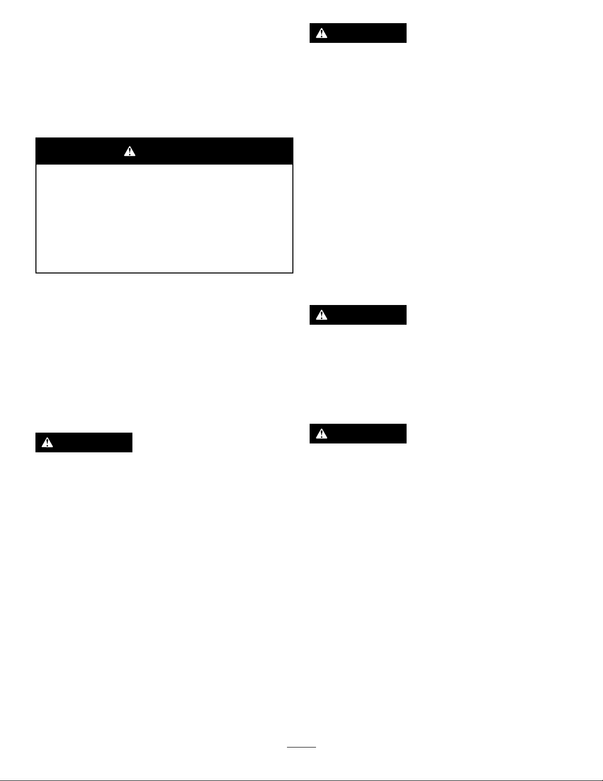
ElectricalSystem
Maintenance
ServicingtheBattery
WARNING
Abatterycontainssulfuricacid,whichcancause
seriousburns;anditcanproduceexplosivegases.
•Avoidcontactwithskin,eyes,orclothing;ush
affectedareaswithwater.
ServiceInterval:Every50hours—Checkthebattery
condition.
WARNING
CALIFORNIA
Proposition65Warning
Batteryposts,terminals,andrelated
accessoriescontainleadandleadcompounds,
chemicalsknowntotheStateofCalifornia
tocausecancerandreproductiveharm.
Washhandsafterhandling.
Important:Beforeweldingonthemachine,disconnect
thenegativecablefromthebatterytopreventdamageto
theelectricalsystem.Also,disconnecttheengineand
machinecontrollerbeforeweldingonthemachine.
Note:Checkthebatteryconditionweeklyorafterevery50
hoursofoperation.Keeptheterminalsandtheentirebattery
casecleanbecauseadirtybatterydischargesslowly.Toclean
thebattery,washtheentirecasewithasolutionofbakingsoda
andwater.Rinsewithclearwater.Coatthebatterypostsand
cableconnectorswithGrafo112X(skin-over)grease(Toro
PartNo.505-47)orpetroleumjellytopreventcorrosion.
•Iftakeninternally,drinklargequantitiesofwater
ormilk.
attentionimmediately.
•Keepsparks,ames,andlitcigarettesandcigars
awayfromthebattery.
•Ventilatethebatterywhenyouarechargingitor
usingitinanenclosedarea.
•Weareyeprotectionwhenworkingneara
battery.
•Washyourhandsafterhandlingabattery.
•Keepthebatteryoutofthereachofchildren.
Do not
inducevomiting.Seekmedical
WARNING
Ifyoutrytochargeorjumpstartafrozenbattery,it
couldbeexplosive,causingpersonalinjurytoyou
orothersinthearea.
Topreventthebatteryelectrolytefromfreezing,
keepthebatteryfullycharged.
WARNING
Exposuretobatteryacidorabatteryexplosioncan
causeseriouspersonalinjury.
Beforeyouserviceabattery,wearfaceprotection,
protectivegloves,andprotectiveclothing.
WARNING
•Sparksoraamecancausehydrogengasina
batterytoexplode.
•Whenyoudisconnectthebatterycables,
disconnectthenegative(-)cablerst.
•Whenyouconnectthebatterycables,connect
thenegative(-)cablelast.
•Donotshort-circuitthebatterypostswitha
metalobject.
•Donotweld,grind,orsmokenearabattery.
Note:Theelectricalsysteminthismachineis12volts.
92
Page 93

ChargingtheBattery
1
2
3
4
G003792
WARNING
Chargingthebatteryproducesgassesthatcan
explode.
Donotsmokenearthebattery,andkeepsparksand
amesawayfromthebattery.
Important:Keepthebatteryfullycharged.Thisis
especiallyimportanttopreventbatterydamagewhen
thetemperatureisbelow32°F(0°C).
Battery-chargerTable
ChargersettingChargingtime
4to6amperes30minutes
25to30amperes10to15minutes
8.Whenthebatteryisfullycharged,unplugthecharger
fromtheelectricalsource,thendisconnectthecharger
leadsfromthebatteryposts(Figure130).
Jump-startingtheMachine
1.Parkthemachineonalevelsurface,stoptheengine,
andremovetheignitionkey.
2.Openthefronthood.
3.Cleantheexteriorofthebatterycaseandthebattery
posts.
Note:Connecttheleadsofthebatterychargerto
batterypostsbeforeconnectingthechargertothe
electricalsource.
4.Lookatthebatteryandidentifythepositiveand
negativebatteryposts.
5.Connectthepositiveleadofthebatterychargertothe
positivebatterypost(Figure130).
WARNING
Jump-startingthebatterycanproducegassesthat
canexplode.
Donotsmokenearthebattery,andkeepsparksand
amesawayfrombattery.
Note:Thisprocedurerequires2peopletoperform.Ensure
thatthepersonmakingtheconnectionswearstheproperface
protection,protectivegloves,andclothing.
1.Parkthemachineonalevelsurface,stoptheengine,
andremovetheignitionkey.
2.Openthefronthood.
3.EnsurethatallcontrolsareintheNeutralposition.
4.Sitintheoperatorseatandhavetheotherpersonmake
theconnections.
Note:Ensurethatthejumperbatteryisa12-volt
battery.
Important:Ifyouareusinganothermachine
forpower,ensurethatthe2machinesarenot
touchingeachother.
5.Preparetostarttheengine;refertoStartingand
StoppingtheEngine(page62).
6.Removethecoverfromthejumppost(Figure131).
Figure130
1.Positivebatterypost
2.Negativebatterypost
6.Connectthenegativeleadofthebatterychargertothe
negative-batterypost(Figure130).
7.Connectthebatterychargertotheelectricalsource,and
chargethebatteryaccordingtotheBattery-charging
Tablethatfollows.
Important:Donotoverchargethebattery.
3.Red(+)chargerlead
4.Black(-)chargerlead
93
Page 94

Figure131
1.Groundpoint(unpainted
bolt)
2.Jumper-cableclamp
(negative)
3.Jumppost
7.Connectthepositive(+)jumpercabletothejumppost
(Figure131).
4.Cover
5.Jumper-cableclamp
(positive)
DriveSystem
Maintenance
CheckingtheOilLevelforthe
StakedownPlanetaryDrive
ServiceInterval:Aftertherst100hours—Checkthe
stakedownplanetary-driveoillevel(Also,
checkifexternalleakageisobserved).
Every500hours—Checkthestakedown
planetary-driveoillevel(Also,checkifexternalleakage
isobserved).
Oilspecication:SAE85W -140APIclassicationlevelGL4
Planetary-driveoilcapacity:approximately1.2L(2.5US
pt)
ToroPremiumGearOilisavailablefromanAuthorizedToro
ServiceDealer.Seethepartscatalogforpartnumbers.
1.Checktheoillevelonthesight-glassoneachstakedown
planetarydrive(Figure132).
8.Connectthenegative(-)jumpercabletoaground
point,suchasanunpaintedboltorchassismember
(Figure131).
9.Starttheengine;refertoStartingandStoppingthe
Engine(page62).
Important:Iftheenginestartsandthenstops,
do not
motorstopsturning.
motorformorethan30secondsatonetime.Wait
30secondsbeforeoperatingthestartermotorto
coolthemotorandtobuildupthechargeinthe
battery.
10.Whentheenginestarts,havetheotherperson
disconnectthenegative(-)jumpercablefromthe
frameandthendisconnectthepositive(+)jumper
cable(Figure131).
operatethestartermotoruntilthestarter
Do not
operatethestarter
Note:Theoillevelshouldcoverhalfofthesight-glass.
Figure132
1.Sight-glass
2.Removethebreathercapandaddtheoilintothe
planetarydriveuntiltheoillevelonthesight-glassisat
leasthalffull(Figure132).
3.Repeatfortheotherstakedownplanetary.
94
2.Breathercap
Page 95

CheckingtheOilLevelforthe
ChangingtheOilfortheTracks
TracksPlanetaryDrive
ServiceInterval:Every50hours—Checkthetracksrotary
motorplanetary-driveoillevel(Also,
checkifexternalleakageisobserved).
Oilspecication:SAE85W -140APIclassicationlevelGL4
Planetary-driveoilcapacity:approximately1.4L(1.5US
pt)
ToroPremiumGearOilisavailablefromanAuthorizedToro
ServiceDealer.Seethepartscatalogforpartnumbers.
1.Parkthemachineonalevelsurface,stoptheengine,
andremovetheignitionkey.
2.Cleantheareaaroundtheoil-levelplugwithacleaning
solvent(Figure133).
PlanetaryDrive
ServiceInterval:Aftertherst250hours—Changethe
planetary-driveoil.
Every800hours—Changetheplanetary-driveoil(or
yearly,whichevercomesrst).
Note:Changetheoilwhenitiswarm,ifpossible.
1.Parkthemachineonalevelsurface.
2.Cleantheareaaroundtheoil-levelplug(Figure133).
3.Rotatetheplanetarydriveuntiltheoil-drainplugis
directlybelowtheoil-levelplug(Figure133).
4.Stoptheengineandremovethekey.
5.Placeadrainpanundertheoil-drainplug.
6.Removetheoil-levelplugandtheoil-drainplug.
7.Installtheoil-drainplug.
8.Fillthechaindriveplanetarywithoiluntiltheoilis
evenwiththebottomoftheoil-levelplughole.
9.Installtheoil-levelplug.
10.Repeatsteps1through9tochangetheplanetary-drive
oilontheothersideofthemachine.
Figure133
1.Oil-levelplug2.Oil-drainplug(6o’clock
3.Removetheoil-levelplug(Figure133).
Note:Theoilleveliscorrectwhenitisuptothe
bottomoftheoil-levelplughole.
4.Iftheoilisbelowthebottomofthehole,addthe
speciedoiluntiltheoilislevelwiththebottomof
thehole.
5.Installandtightentheoil-levelplug.
position)
95
Page 96

CheckingtheOilLevelforthe
CheckingtheOilfortheThrust
RotaryMotorPlanetaryDrive
ServiceInterval:Aftertherst100hours—Checktherotary
motorplanetary-driveoillevel(Also,
checkifexternalleakageisobserved).
Every500hours—Checktherotarymotor
planetary-driveoillevel(Also,checkifexternalleakage
isobserved).
Oilspecication:SAE85W -140APIclassicationlevelGL4
Planetary-driveoilcapacity:approximately0.24L(0.5US
pt)
ToroPremiumGearOilisavailablefromanAuthorizedToro
ServiceDealer.Seethepartscatalogforpartnumbers.
1.Parkthemachineonalevelsurface,stoptheengine,
andremovetheignitionkey.
2.Checktheoillevelonthesight-glassontherotary
motorplanetarydrive(Figure134).
Note:Theoillevelshouldbe3/4fullinthesight-glass.
MotorPlanetaryDrive
ServiceInterval:Aftertherst100hours—Checkthethrust
motorplanetary-driveoil.
Every500hours—Checkthethrustmotor
planetary-driveoil(oryearly,whichevercomesrst).
Oilspecication:SAE85W -140APIclassicationlevelGL4
Planetary-driveoilcapacity:approximately0.24L(0.5US
pt)
1.Parkthemachineonalevelsurface,stoptheengine,
andremovetheignitionkey.
2.Checktheoillevelonthesight-glassoneachthrust
motorplanetarydrive(Figure136).
Note:Theoillevelshouldcoverhalfofthesight-glass.
Figure134
1.Rotarymotoroilcap
3.Iftheoillevelislow,removetheoil-levelplug(Figure
134).
4.Installandtightentheoil-levelplug.
2.Sight-glass
Figure135
1.Breathercap
3.Removethebreathercapandaddtheoilintothe
planetarydriveuntiltheoillevelonthesight-glassisat
leasthalffull(Figure136).
4.Repeatforall4thrustmotorplanetarydrives.
96
2.Sight-glass
Page 97

CheckingtheOilforthe
ChangingtheOilforthe
GearboxDrive
ServiceInterval:Aftertherst100hours—Checkthe
gearboxdriveoil.
Every500hours—Checkthegearboxdriveoil(or
yearly,whichevercomesrst).
Oilspecication:SAE85W -140APIclassicationlevelGL4
Planetary-driveoilcapacity:approximately2.7L(5.75US
pt)
1.Parkthemachineonalevelsurface,stoptheengine,
andremovetheignitionkey.
2.Checktheoillevelonthesight-glassonthegearbox
drive(Figure136).
Note:Theoillevelshouldcoverhalfofthesight-glass.
GearboxDrive
ServiceInterval:Aftertherst100hours—Changethe
gearbox-driveoil.
Every500hours—Changethegearbox-driveoil(or
yearly,whichevercomesrst).
Note:Changetheoilwhenitiswarm,ifpossible.
1.Parkthemachineonalevelsurfaceandmovethe
carriageallthewaytotherearstop.
Figure136
1.Sight-glass
3.Removethebreathercapandaddtheoilintothe
gearboxdriveuntiltheoillevelonthesight-glassisat
leasthalffull(Figure136).
Figure137
2.Stoptheengineandremovetheignitionkey.
97
Page 98
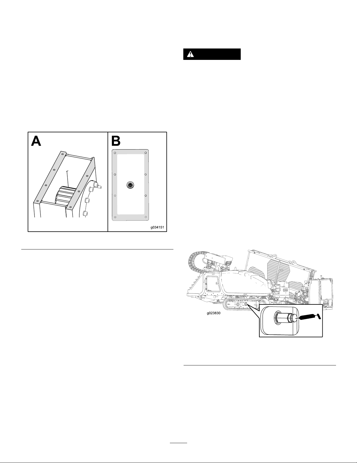
3.Removethe2boltsandnutsonthecarriageguard
(BoxBofFigure137).
4.Removethe2boltsandnutsonthesideofthecarriage
guard(BoxCofFigure137).
ServicingtheTracks
ServiceInterval:Beforeeachuseordaily—Checkthetrack
tension.
5.Slidethecarriageguardforward(BoxDofFigure137).
6.Removethe6boltsonthegearbox(BoxEofFigure
137).
7.Removethecoveronthegearboxandsyphontheoil
out(BoxFofFigure137).
8.Fillthegearboxwithoiluntiltheoillevelinthesight
glassismorethanhalffull(Figure136).
9.Cleanthesealantoffofthegearboxboxandcover
(Figure138).
WARNING
Greaseinthehydraulictrackishighlypressurized;
ensurethatthetrack-tensiongreasevalveisnot
loosenedmorethan1revolutionatatime.
Ifyouremovethetrack-tensiongreasevalve(found
inthehydraulic-tracktensioner)orloosenittoo
much,greasecanbereleasedandmaycause
seriousinjuryordeath.
TighteningtheTrackTension
Ifthetrackseemsloose,tightenthetracktensionasfollows:
1.Parkthemachineonalevelsurface,stoptheengine,
andremovetheignitionkey.
2.Removedirtanddebrisfoundaroundthetrack-tension
greasevalve(Figure139).
Important:Ensurethattheareasurrounding
thetrack-tensiongreasevalveiscleanbefore
beginningtoadjustthetracktension.
3.Removetheretainingboltsandcoverthathousethe
track-tensiongreasevalve.
Figure138
10.Putnewautomotive-gradeRTVsealantaroundthe
edgeofthecover(BoxBofFigure138).
11.Slidethecoverbackontothegearboxandloosely
installthe6bolts(BoxEofFigure137).
12.Placethecarriageguardbackintoplaceandloosely
installthe2bolts(BoxCofFigure137).
13.Installthe2boltssecuringthecarriageguardontothe
gearbox(BoxBofFigure137).
14.Tightenthe6boltsonthegearboxandthe2boltson
thesideofthecarriageguard.
4.Applygreasetothettinguntilthetensionreaches
31,026kPa(4,500psi)asshowninFigure139.
Figure139
Track-tensiongreasevalveshown
5.Removeexcessgreasefromaroundthevalve.
6.Installthecoverandretainingbolts.
7.Repeatsteps2through6totightenthetracktension
ontheotherside.
98
Page 99

LooseningtheTrackTension
Ifthetrackseemstight,loosenthetracktensionasfollows:
1.Parkthemachineonalevelsurface,stoptheengine,
andremovetheignitionkey.
2.Removedirtanddebrisfoundaroundthetrack-tension
greasevalve(Figure139).
Important:Ensurethattheentirearea
surroundingthetrack-tensiongreasevalveisclean
beforebeginningtoadjustthetracktension.
3.Removetheretainingboltsandthecoverthathouse
thetrack-tensiongreasevalve.
4.Turnthetrack-tensiongreasevalvecounterclockwise
nomorethan1revolution(Figure139).
Note:A1-revolutionturnwillreleasegreaseand
loosenthetrack.
5.Whenthetensionreaches31,026kPa(4,500psi),turn
thetrack-tensiongreasevalveclockwisetotightenit.
6.Removeexcessgreasefromaroundthevalve.
7.Installthecoverandretainingbolts.
8.Repeatsteps2through7toloosenthetracktensionon
theotherside.
CoolingSystem
Maintenance
Coolantspecication:50/50solutionofethylene-glycol
antifreezeandwaterorequivalent
EngineandRadiatorcoolantcapacity:16.8L(17.7USqt)
WARNING
Ifyouremovetheradiatorcapfromahotengine,
hotcoolantcouldspray,causingscalding.
•Wearfaceprotectionwhenopeningtheradiator
cap.
•Allowthecoolingsystemtocooldowntobelow
50°C(120°F)beforeremovingtheradiatorcap.
•Followtheinstructionsforcheckingand
maintainingtheenginecoolingsystem.
WARNING
Coolantistoxic.
•Keepcoolantawayfromchildrenandpets.
•Ifyouarenotusingthesamecoolantagain,
disposeofitaccordingtolocalenvironmental
regulations.
99
Page 100
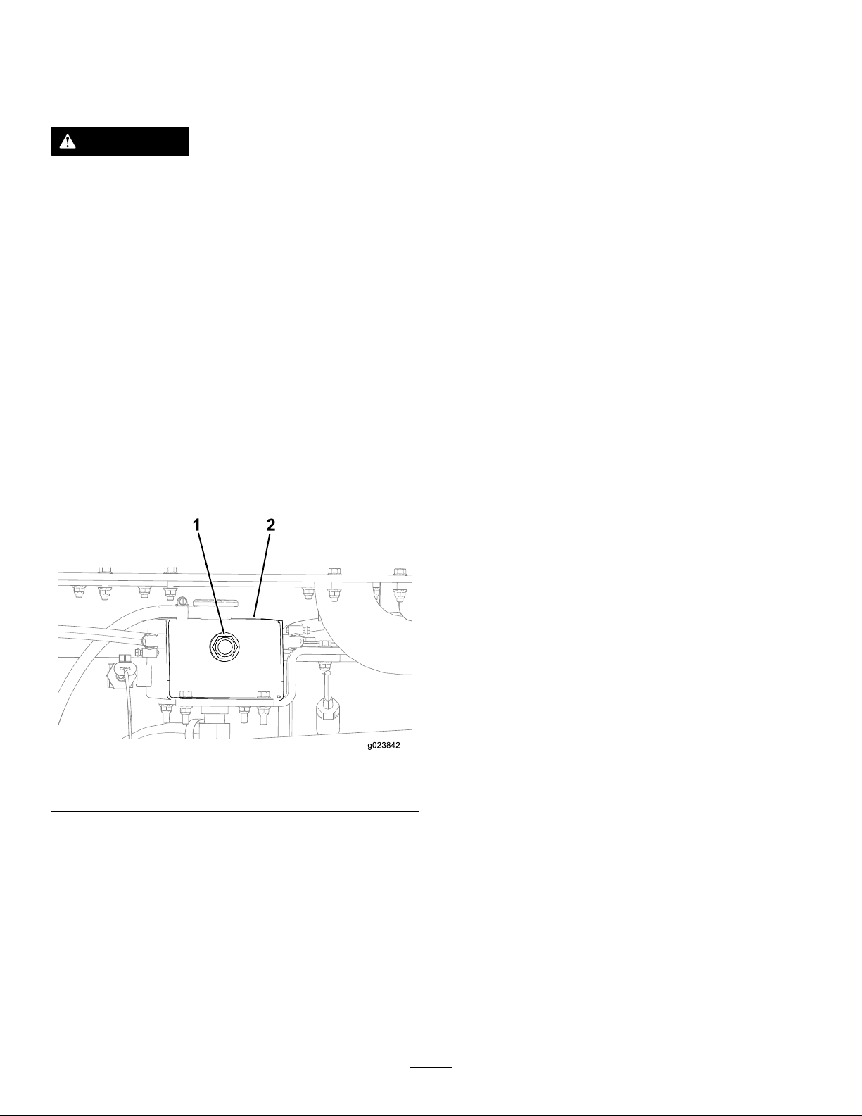
CheckingtheCoolantLevelin
CheckingtheConditionof
theRadiator
ServiceInterval:Beforeeachuseordaily
WARNING
Iftheenginehasbeenrunning,theradiatorwillbe
pressurizedandthecoolantinsidewillbehot.If
youremovethecap,coolantmaysprayout,causing
severeburns.
Donotremovetheradiatorcapwhentheengineis
hot.Allowtheenginetocoolforatleast15minutes
oruntiltheradiatorcapiscoolenoughtotouch
withoutburningyourhand.
Note:Thecoolingsystemislledwitha50/50solutionof
waterandethylene-glycolantifreeze.
1.Parkthemachineonalevelsurface,stoptheengine,
andremovetheignitionkey.
2.Allowtheenginetocool.
3.Opentherear-accessdoor.
4.Checkthecoolantlevelbylookingatthesightgaugeat
theendoftheradiatortank(Figure140).
Cooling-systemComponents
ServiceInterval:Every300hours/Yearly(whichevercomes
rst)
Checktheconditionofthecoolingsystemforleaks,damage,
dirt,andloosehosesandclamps.Clean,repair,tighten,and
replacethecomponentsasnecessary.
CheckingtheConcentrationof
theCoolant
ServiceInterval:Every1,000hours/Yearly(whichever
comesrst)—Checktheconcentration
ofthecoolantbeforethewinterseason.
Testtheconcentrationofethyleneglycol-basedantifreeze
inthecoolant.Ensurethatthecoolanthasa50%ethylene
glycoland50%watermixtureorequivalent.
Note:A50%ethyleneglycoland50%watermixturewill
protecttheengineto-37°C(-34°F)throughouttheyear.
Usingaconcentrationtester,checktheconcentrationof
thecoolantmixturetoensurethatitis50%ethyleneglycol
and50%waterorequivalent;refertothemanufacturer’s
instructionsfortesting.
Figure140
1.Coolanttanksightgauge2.Endoftheradiatortank
•Ifthecoolantlevelislow ,addcoolantuntilthe
levelisuptothebottomofthellerneck;referto
FillingtheSystemwithCoolant(page102).
Important:Donotoverlltheradiator.
•Ifthecoolantlevelisnormal,closetherear-access
door.
CleaningtheCoolingSystem
ServiceInterval:Every1,000hours/Yearly(whichever
comesrst)(Cleanthecoolingsystem
ifthecoolantbecomesdirtyorrust
colored.)
100
 Loading...