

Page 1
4045and4050DirectionalDrill
SoftwareVersionsA–C
ModelNo.23823/A/C/TE/W—SerialNo.315000001andUp
ModelNo.23825/A/C/TE/W—SerialNo.315000001andUp
ModelNo.23898—SerialNo.400000000andUp
ModelNo.23899—SerialNo.400000000andUp
Readthisinformationcarefullytolearnhowtooperate
andmaintainyourproductproperlyandtoavoid
injuryandproductdamage.Youareresponsiblefor
operatingtheproductproperlyandsafely.
Wheneveryouneedservice,genuineToroparts,or
additionalinformation,contactanAuthorizedService
DealerorToroCustomerServiceandhavethemodel
andserialnumbersofyourproductready.
YoumaycontactT orodirectlyatwww.T oro.com
forproductsafetyandoperationtrainingmaterials,
accessoryinformation,helpndingadealer,orto
registeryourproduct.
FormNo.3419-198RevA
SoftwareGuide
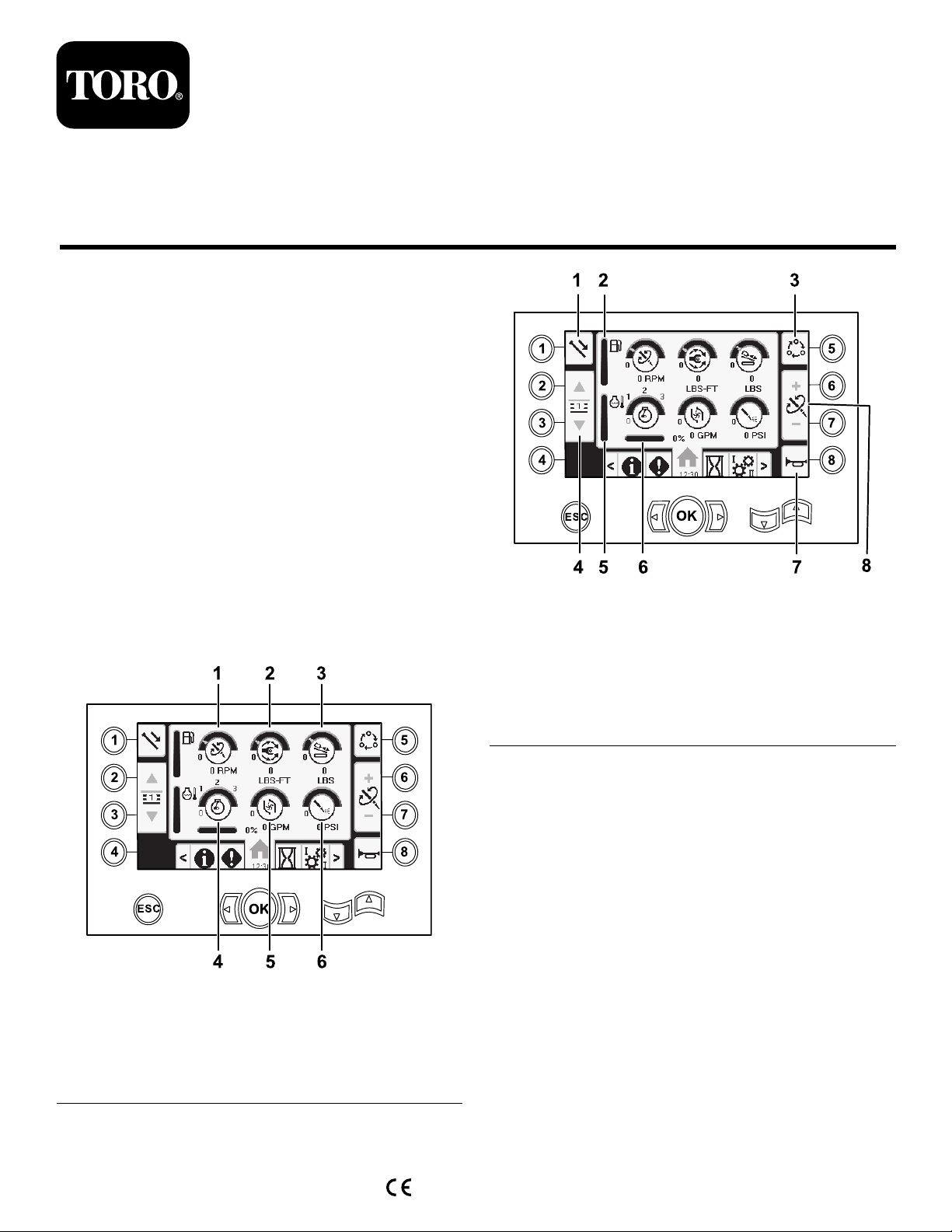
MainInformationScreen
Thisistherstscreenthatappearsaftertheinitial
splashscreen.Tonavigatebetweenscreens,usethe
leftandrightarrows.
Figure1
1.Drillspeed(rpm)4.Enginespeed(rpm)
2.Rotarytorque
3.Thrustforce6.Drilling-uid/Air-hammer
5.Drilling-uidowrate
pressure
g214634
Figure2
1.Pipefunctions
2.Fuelgauge6.Enginedroop
3.Limitsettingoptions7.Horn
4.Selectpiperow8.Thrustforce,drillspeed
5.Enginetemperaturegauge
(rpm),orrotarytorque
adjustment
GototheMudorAirHammerSelectionScreen(page
12)toswitchbetweenmudpressureandairhammer
functions.
Pushbutton1toswitchbetweenthepipefunctions
pullpipe,pushpipe,andneutral.
Pushbutton5toswitchbetweenthrustforce,drill
speed(rpm),androtarytorquelimits.
Usetheupanddownarrowstosetthelimitsfor
maximumdrillspeed(rpm),rotarytorque,andthrust
g214633
force.
•Thrustforce:Changethethrustforcelimitby
pushing6or7.
•Drillspeed(rpm):Changethedrillspeedrpmlimit
bypushing6or7.
•Rotarytorque:Changetherotarytorquelimitforce
bypushing6or7.
©2017—TheT oro®Company
8111LyndaleAvenueSouth
Bloomington,MN55420
Registeratwww.Toro.com.
OriginalInstructions(EN)
PrintedintheUSA
AllRightsReserved
*3419-198*A
Page 2
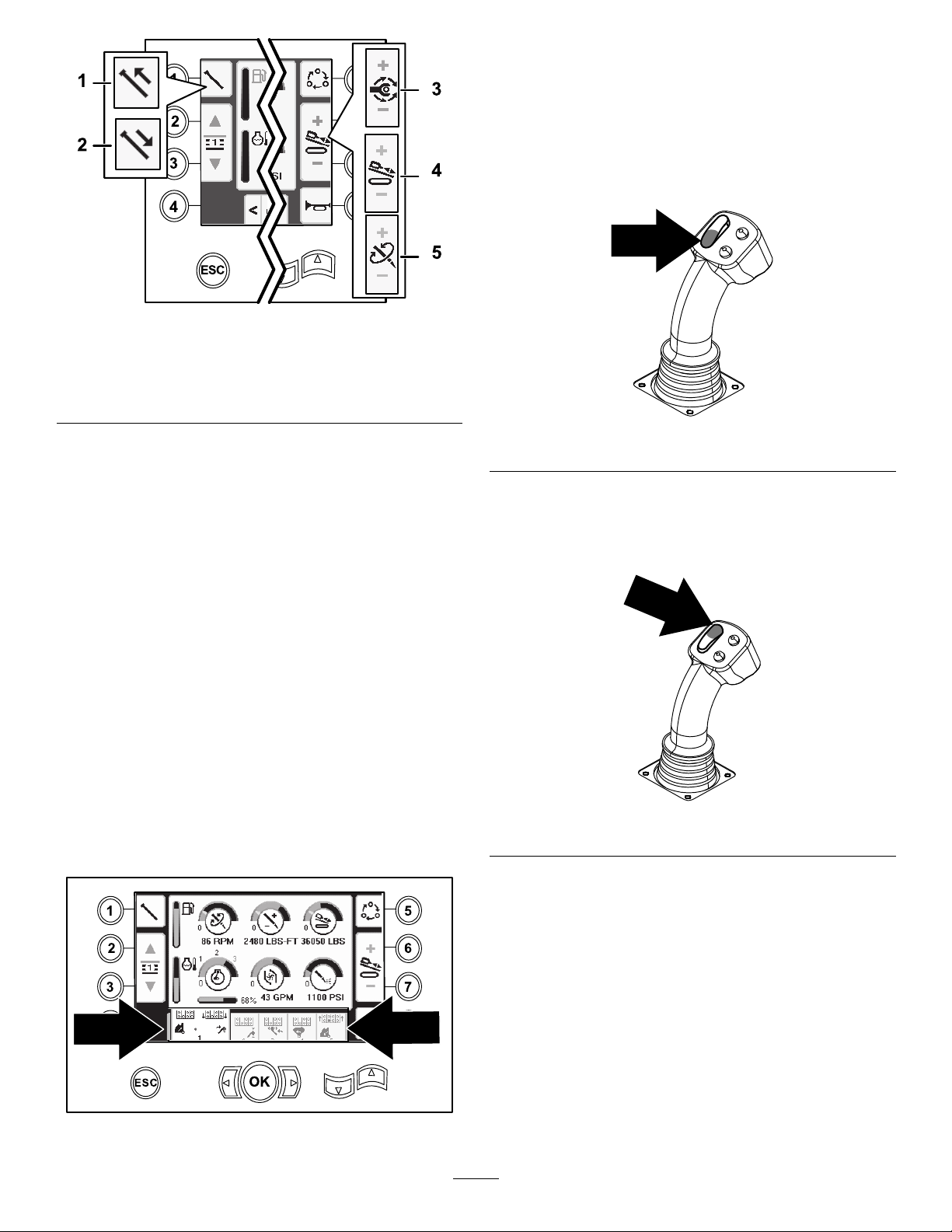
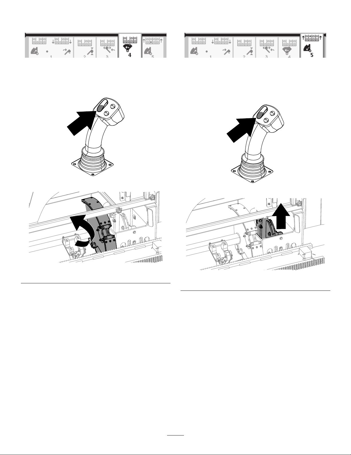
Figure3
PullingPipeinSmartTouchMode
StarttheSmartTouchmodewiththecamassemblyin
thehomeposition(row4ofthepipebox).
Important:Ensurethatyouholdthelowersection
ofthecamrockerswitch,ontheleftjoystick,
completelydownuntiltheactioniscompletein
eachstep(Figure5).
g213150
1.Pullpipe
2.Pushpipe
3.Rotarytorque
4.Thrustforce
5.Drillspeed(rpm)
SmartTouch™Home Screen
SmartTouchmodeallowstheoperatortoloadand
unloadpipesfromtherodboxwithlessjoystick
operationtoreduceoperatorfatigue.
UsetheCarriageSettingsScreen(page10)toturn
SmartTouchmodeonandoff.
Note:ThePush/PullIconshaveagreenbackground
whenSmartTouchmodeisonandaribbonappears
atthebottomofthescreenshowingasequenceof
thesteps.
Important:NeverswitchbetweenPush/Pull
modesduringthechosenoperation.Useneutral
(manual)modetoswitchbetweenPush/Pull;refer
toCarriageSettingsScreen(page10)toturn
SmartTouchmodeoff.
TheSmartTouchscreensappearsalongthebottomof
thehomescreenasshownbelow.
g210060
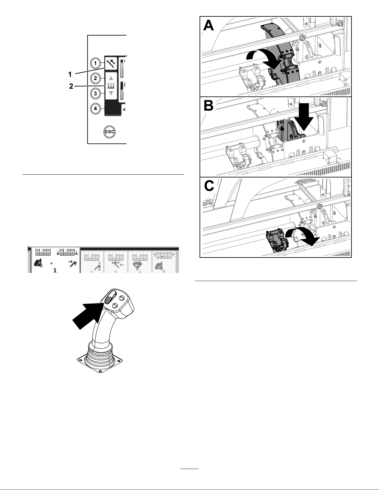
Figure5
Holdtheuppersectionofthecamrockerswitch,
ontheleftjoystick,completelydownuntilall
actionsarecompletetogotothepreviousstepin
thesequence(Figure6).
g210061
Figure6
1.Pushbutton1toselectthepullpipeoption
(Figure7).
Figure4
g231722
2
Page 3
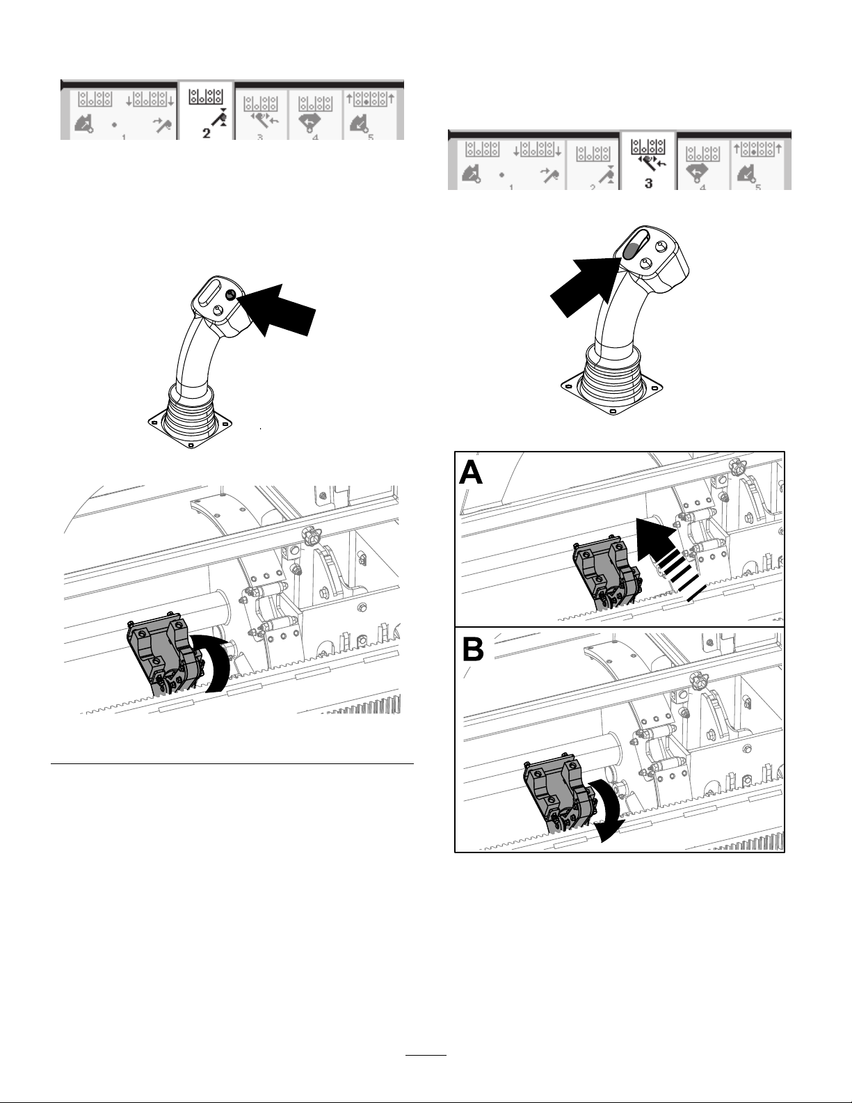
2.Pushbuttons2and3toselecttherowwhere
youwanttoplacethepipe(Figure7).
Figure7
g232381
1.Pullpipe
2.Selectpiperow
3.Holdthelowersectionoftherockerswitch
(Figure9)untilthefollowing3thingshappen
(Figure10):
A.Thecamassemblyrotatestowardthe
operatorstation.
B.Theelevatorlowers.
C.Theloaderarmsrotatetothedrillpipe.
Figure8
g232376
Figure10
g231712
Figure9
g210462
3
Page 4
4.Releasetherockerswitchtoproceedtothenext
stepinthesequence(Figure11).
Figure11
7.Holdthelowersectionoftherockerswitch
(Figure15)untilthearmsrotatewiththepipe
backtothehomepositionandthegrippersopen
asthepipeentersthecamassemblypocket
(Figure16).
g231713
5.Breakthepipeconnection;refertoRemoving
DrillPipesintheOperator’sManual.
6.Holdtheupperbuttononthejoysticktogripthe
pipe(Figure12andFigure13)andreleasethe
button.
Figure12
g231714
Figure14
g210462
Figure15
g210533
Figure13
g232377
g232378
Figure16
4
Page 5
8.Releasetherockerswitchtoproceedtothenext
stepinthesequence(Figure17).
10.Releasetherockerswitchtoproceedtothenext
stepinthesequence(Figure20).
Figure17
9.Holdthelowersectionoftherockerswitch
(Figure18)untilthecamassemblyrotatestothe
selectedrowunderthepipebox(Figure19).
Figure18
g231715
g231716
Figure20
11.Holdthelowersectionoftherockerswitch
(Figure21)untiltheelevatorputsthepipeback
inthepipeboxandthecamrotatestothehome
position(Figure22).
g210462
g210462
Figure21
Figure19
g232379
g232380
Figure22
12.Releasetherockerswitchtostartthepull-pipe
processagain.
5
Page 6

PushingPipeinSmartTouchMode
StarttheSmartTouchmodewiththecamassemblyin
thehomeposition(row4ofthepipebox).
Important:Ensurethatyouholdthelowersection
ofthecamrockerswitch,ontheleftjoystick,
completelydownuntiltheactioniscompletein
eachstep(Figure23).
g232387
Figure25
Figure23
Holdtheuppersectionofthecamrockerswitch,
ontheleftjoystick,completelydownuntilall
actionsarecompletetogotothepreviousstepin
thesequence(Figure24).
Figure24
1.Pushpipe
g210060
3.Holdthelowersectionoftherockerswitch
(Figure27)untilthecamassemblyrotatestothe
2.Selectpiperow
selectedrowandtheelevatorlowersthepipe
intotheopening(Figure28).
g231717
Figure26
g210061
Figure27
g210462
1.Pushbutton1toselectpushpipe(Figure25).
2.Pushbuttons2and3toselecttherowwhere
youwanttogetthepipe(Figure25).
g232382
Figure28
6
Page 7

4.Releasetherockerswitchtoproceedtothenext
stepinthesequence(Figure29).
6.Releasetherockerswitchtoproceedtothenext
stepinthesequence(Figure32).
Figure29
5.Holdthelowersectionoftherockerswitch
(Figure30)untilthecamassemblyfullyrotates
forwardtotherackandtheelevatorsliftthe
remainingpipeintothepipebox(Figure31).
Figure30
g231718
g231719
Figure32
7.Holdthelowersectionoftherockerswitch
(Figure33)untiltheloaderarmsrotatetoward
thepipebox.Astheyrotatepastthecam
assemblythepipegripperscloseonthepipe,
bringingittothedrillstring(Figure34).
g210462
g210462
Figure33
Figure31
g232383
g232384
Figure34
7
Page 8

8.Releasetherockerswitchtoproceedtothenext
stepinthesequence(Figure35).
Figure35
9.Makethepipeconnection;refertoAddingDrill
PipesintheOperator’sManual.
10.Holdthelowerbuttononthejoystick(Figure
36)toreleasethepipe(Figure37)andrelease
thebutton.
11.Holdthelowersectionoftherockerswitch
(Figure39)untiltheloaderarmsrotatebackand
thecamassemblyreturnstothehomeposition
(row4)(Figure40).
g231720
g231721
Figure38
g210462
Figure39
Figure36
Figure37
g210527
g232385
g232386
Figure40
12.Releasetherockerswitchtostartthepush-pipe
processagain.Thecamassemblygoesto
therowpickedinstep2ofPullingPipein
SmartTouchMode(page2).
8
Page 9

HoursScreenOptions
LubricationandMaintenance Screens
MachineHoursScreen
Toaccessthisscreen,pushbutton1ontheHours
screen.
Thisscreenshowstheoperatinghoursofthe
machine.YoucannotchangeMachine1butyoucan
resetMachine2.
Figure41
Toaccessthisscreen,pushbutton3ontheHours
screen.
Thesescreensprovidetheuserwiththedaily
maintenanceschedulesintheincrementslistedbelow.
Toresetthemaintenanceinterval,navigatetothe
ParametersOptionsScreen(page11),pushthedown
arrowtoscrolltothemaintenanceoptionsscreen,and
enterpinnumber12356.
Pushthefollowingbuttonstoattainthesubsequent
maintenanceschedule:
•Button3—10-hour/Daily(Figure43)
•Button5—50-hour(Figure44)
•Button6—250-hour(Figure45)
•Button7—500-hour(Figure46)
•Button8—1,000-hour(Figure47)
g213163
MudUseScreen
Toaccessthisscreen,pushbutton2ontheHours
screen.
Thisscreenshowsthemudvolumeused.
Toswitchbetweengallonsandliters,refertoFigure
51,LanguageandUnitsOptionsScreen(page1 1).
Youcannotchangethetotalmud,butyoucanreset
thedailymudusingbutton8.
g034777
Figure43
Figure42
g034784
g034778
Figure44
9
Page 10

Figure45
SettingsScreenOptions
CarriageSettingsScreen
Pushbutton1ontheSettingsscreen.
Usethisscreentochangethecarriagesettings.Use
theupanddownarrowstorotatebetweenpushpipe,
pullpipe,andneutral.
PushtheOKbuttontoturnSmartTouch™onandoff.
g034779
g233212
Figure48
Figure46
Figure47
ControlModeScreen
Pushbutton2ontheSettingsscreen.
g034780
g034781
Usethisscreentoselectbetweenthe2joystick
controloptions.Pushtheupanddownarrowstoto
switchbetweenModeIandModeII.
g224024
Figure49
•ModeI—Therightjoystickcontrolsthethrustand
therotationfunctions.Theleftjoystickcontrolsthe
wrenchandpipeloaderfunctions.
•ModeII—Therightjoystickcontrolsthethrustand
thepipeloaderelevatorfunction.Theleftjoystick
controlstherotation,wrench,andpipeloader
functions.
10
Page 11

ParametersOptionsScreen
ScreenSettings
Pushbutton3ontheSettingsscreen.
Thepinnumbertochangetheparametersis
73236531.
Pushthedownarrowtoscrolltothemaintenance
optionsscreentoresetthemaintenanceinterval.
Enterpinnumber12356.
Figure50
Pushbutton6ontheSettingsscreentoswitch
betweenzoomdelay,brightness,anddayornight
mode.Usetheupanddownarrowstoadjustthe
parameters.
TheMainDrillingScreenzoomsintothedrilling
functions.Thesesettingsadjustthedelayonhow
longittakestozoom.
g224027
Figure52
g224028
LanguageandUnitsOptions Screen
Pushbutton5ontheSettingsscreentoaccessthe
languageandunitsScreen.Pushtheupanddown
arrowstoswitchbetweenEnglishunitsandmetric
units.
Figure51
ClockSettingsScreen
Pushbutton7ontheSettingsscreentoswitch
betweentheclockoptions.Usetheupanddown
arrowstoadjusttheparameters.
Onceyouareonthisscreen,pushbutton7torotate
betweendate,time,and12/24.
g224026
g224023
Figure53
11
Page 12

MudorAirHammerSelection Screen
Pushbutton8ontheSettingsscreentoaccessthis
screen.Usetheupanddownarrowstoswitchbeen
mudandairhammer.
Thisupdatesthedisplayonthehomescreen(Figure
1).
Figure54
•Therotaryvoltagerangesfrom0.0to8.5Vand
canbepresentforeithermake(uppericon)or
break(lowericon)astheselectedrotaryjoystickis
moved.
•Thecarriageindicatesavoltagerangefrom0.0to
10.0Vinthejoystickselecteddirectionforthrust
orpullback.
•Thelowerlefticonindicatesthecarriageposition
ofwrench,load,orcarriagebackasthecarriage
movestothemostrearwardpositions.
•Thelowercentericonindicatesifthe2-speed
selectionofthecarriagespeedhasbeenselected.
•ThelowerrighticonindicatesthestatusoftheExit
SideLockout(ESL).Iftheindicatorisblack,the
carriageandrotaryactionsareinhibited.
EngineI/OScreen
Toaccessthisscreenpushbutton2ontheI/Oscreen.
g233213
Thisscreendisplaysengineinformation.
I/OScreens
JoystickI/OScreen
Pushbutton1ontheI/Oscreentorotatebetweenthe
DrillandSetupoptions.Theiconturnsgreenwhen
theassociatedfunctionisactuated.
Whentherockerswitchontheleftcontrolpanelisin
theDrillposition,theupperlefticonturnsgreenand
thejoystickvoltagescanbecheckedaswellasverify
the2-Speed,andExitSideLockoutinputs.
WhentherockerswitchisintheSetupposition,the
upperrighticonisgreen.Thesetuppositionallows
youtomovethemachineandpreparefordrilling.
Figure56
1.Enginespeed(rpm)6.Air-lterindicator
2.Engine-oilpressure
3.Batteryvoltage8.Engineload
4.Enginetemperature9.Enginedroop
5.Hydraulic-uid
temperature
7.Hydraulic-uidlter
g213149
Figure55
Enginespeed(rpm)icon:displays,instepsof100,
theenginespeed(rpm).
Engine-oilpressureicon:displaystheengine-oil
g224025
pressure(barorpsi).
Batteryvoltageicon:displaysthebatteryvoltage.
12
Page 13

•Iftheengineisshutoff,thevoltageismeasured
bytheT orocontroller.
•Iftheengineisrunning,thevoltageissuppliedby
enginecontroller.
Enginetemperatureicon:displaystheengine
coolanttemperaturemeasuredatthereservior.The
temperaturedropsto40°Fwhentheengineisshutoff.
Airltericon:theairltericonisgreenunlessthe
lterispluggedthentheindicatorisred.
Hydraulic-uidltericon:thehydraulic-uidlter
iconisgreenunlessthelterispluggedthenthe
indicatorisred.
Engineloadicon:displaysthepercentoftheengine
load.
Enginedroopicon:selecttheallowableengine
droopof80,90,or100%.Thedroopvalueisthe
lowestpointbelowlow-loadspeed(rpm)(under75
percentload)thattheenginemaydecreasebefore
thedrivetotherotaryheadisdecreasedtomaintain
thelowestvalue.Pushtheupanddownarrowsto
selectthedroopvalue.
CamArmI/OScreen
Toaccessthisscreenpushbutton3ontheI/Oscreen.
Usethisscreentoadjustthecamandpipeloader
calibrationoptions.
orlowerindicateseithersensorfailureorincorrect
calibration.
AuxiliaryI/OScreen
Toaccessthisscreenpushbutton5ontheI/Oscreen.
Alliconschangefromblacktogreenwhenyou
operatetheassociatedfunctions.
Figure58
1.Raise/Lowerelevator
2.Breakoutwrench6.Rotatepipecam
3.Upperorlowerwrench
4.Gripper
5.Loaderarm
7.TJCgrease
g213173
Figure57
1.Pushbutton3tocalibrate.
The2voltagesonthebottomindicatetheloader
armandcamactualvoltagefromthesensors.The
voltagesrangefrom1.0to4.0V.Anyvoltagehigher
ControllerI/OScreen
Toaccessthisscreenpushbutton6ontheI/Oscreen.
g213146
Figure59
1.Seatswitch
2.Exitsidelockout
3.Pedestriangate7.Processorindicator
4.Camoverrideinput
5.Mudpumpstatus
6.Mudpumpow
g213147
13
Page 14

Seatswitchicon:showsanarrowoutwhenthe
operatorseatisempty;theswitchshowsagureicon
whenyouareintheoperatorseat.
•Showstheseatwithanerrorwhentheoperator
seatisunoccupied
•Showstheseatwithagurinewhentheoperator
seatisoccupied
Exitsidelockouticon:changesfromblacktogreen
wheninoperation.
Pedestriangateicon:
•ShownintheUPpositionwithagurine:thegate
isnotinthecorrectpositionfordrilling
•ShownintheDOWNposition:thegateiscorrectly
positionedfordrilling
Camoverrideinputicon:turnsgreenwhenthe
overridebuttonispushedonthejoystick.
TravelPendantI/OScreen
Toaccessthisscreenpushbutton7ontheI/Oscreen.
Thetravelpendantscreenshowsthevoltageand
positionofthejoysticklocatedonthependant.
g213169
Figure60
Mudpumpstatusicon:
•Black:mudpumpisoff
•Yellow:mudpumpisinstandby
•Green:mudpumpisinon
•Greenwith100:mudpumpisinmaxow
Mudpumpowicon:indicatestheinputfromthe
rockerswitchonthejoystick.
•Whentherockerswitchisactuatedup,the
indicatorturnsgreenwithablueup/increasearrow.
•Whentherockerswitchisactuateddown,the
indicatorturnsgreenwithabluedown/decrease
arrow.
•Theiconisblackwhentherockerswitchisnot
pressed.
Processorindicatoricon:showsaredXtoindicate
aproblemwiththeexpansionprocessorlocatednext
tothemaincontroller.
Thereddotappearsinthecenterofthetargetand
theFNR(forward,neutral,reverse)andSteervoltage
shows2.5Vpriortoallowingthedrilltomove.Ifthe
reddottravelsoutsideoftheoutermostblackring,
serviceorreplacethependantwithanewpendant.
Theindicatorstotherightandleftofthecircleshow
thedirectionofthetracktravel.Thevoltagesshow
arangefrom0to10.0V.
ErrorsandMachine InformationScreens
DrillErrorsScreens
Toaccessthisscreenpushbutton1ontheErrorsand
MachineInformationscreen.
Thisscreendisplaysanydrillerrors.
Usetheupanddownarrowstoscrollthroughthe
errors.ContactyourAuthorizedServiceDealerfor
codesthatcannotbecleared.
g213168
Figure61
14
Page 15

EngineErrorsScreen
CarriageCrashWarningIcon
Toaccessthisscreenpushbutton2ontheErrorsand
MachineInformationscreen.
Thisscreendisplaysanyengineerrors.
Usetheupanddownarrowstoscrollthroughthe
errors.ContactyourAuthorizedServiceDealerfor
codesthatcannotbecleared.
Figure62
MachineInformationScreen
Thecarriagecrashwarningscreen(Figure64)
appearsifthefollowingoccurs:
•Thecarriageisinthedrillareaandyoutryto
operatetheloaderarmorpipecamor
•Youtrytooperatethecarriagewhentheloader
armorpipecamisnotinthehomeposition.
g210794
Figure64
g213170
Toclearthiswarning,dothefollowing:
•Movethecamassemblytothehomeposition
and/or
•Reversethecarriage
Toaccessthisscreenpushbutton3ontheErrorsand
MachineInformationscreen.
Thisscreendisplaysthemachineinformation
includingthemodel,serialnumber,andsoftware
version.
Figure63
MaintenanceRequiredIcon
Thisicon(Figure65)displayswhenmaintenanceis
required.
g223939
Figure65
PedestrianGateWarningIcon
g213171
Thisicon(Figure66)displaysifthepedestriangateis
notintheloweredposition.
g223940
Figure66
15
Page 16

StakeDownCageWarningIcon (CEmodelsonly)
Thisicon(Figure67)displaysifthestakedowncage
doorisnotclosed.
Figure67
g223941
16
 Loading...