

Page 1
FormNo.3398-624RevA
DirtandRockStakes
2024and4045DirectionalDrill
ModelNo.23812
ModelNo.23812E
ModelNo.23813
ModelNo.23813E
ModelNo.23814
ModelNo.23814E
ModelNo.23815
ModelNo.23815E
InstallationInstructions
WARNING
CALIFORNIA
Proposition65Warning
ThisproductcontainsachemicalorchemicalsknowntotheStateofCaliforniato
causecancer,birthdefects,orreproductiveharm.
LooseParts
Usethechartbelowtoverifythatallpartshavebeenshipped.
Description
2024Dirtstakes2
2024Rockstakes2
Coupler
Stakepin
O-ring
Locknut(M12)
Bolt(M12-13/4x80mm)
Greasetting
Stakeguide
Guidering
Bolt(M8-11/4x20mm)
RockorDirtstake2
Guidering
Stakeguide
Bolts(M10-11/2x25mm)
Qty.
Use
2
2
2
8
8
2
2
2
8
2
2
6
Installthestakesonthe2024directionaldrill.
Installthestakesforthe4045directionaldrill.
©2015—TheToro®Company
8111LyndaleAvenueSouth
Bloomington,MN55420
Registeratwww.T oro.com.
OriginalInstructions(EN)
PrintedintheUSA.
AllRightsReserved
*3398-624*A
Page 2
InstallingtheStakesonthe
2024DirectionalDrill
PreparingtheMachineandInstalling
theCoupler
Note:Having2peopleoraliftingmechanismmakesiteasier
toinstallthestakes.
1.Positionthethrustframe25.4cm(12inches)offthe
ground,withthestakesintheupposition.
2.Turnofftheengineandthebatterydisconnectswitch.
3.Ifyourmachinehasacage,removethestake-down
cageassembly.
4.Whileholdingthestakes,removetheO-ringsandpins
securingthestakestothemotors(Figure1).
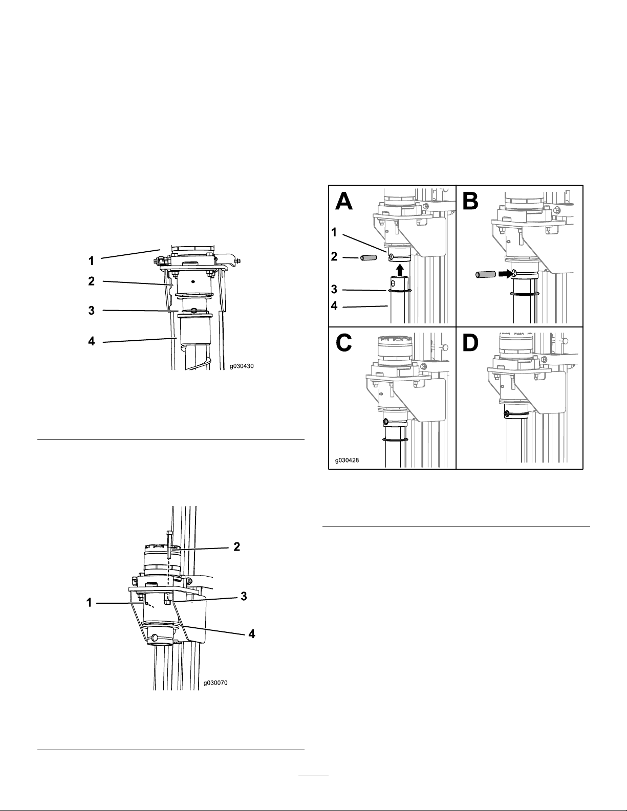
7.Torquetheboltsto127to155N-m(94to114ft-lb).
8.Pumpgreaseintothettingsuntilgreasebeginsto
oozeoutofthebearings(approximately3pumps)and
wipeupanyexcessgrease.
InstallingtheDirtStakesonthe2024
DirectionalDrill
Installthenewstakesbyaligningtheholeinthestakewith
theholeinthemotorcouplerandsecureitwiththeO-rings
andpinsincludedinthiskit(Figure3).
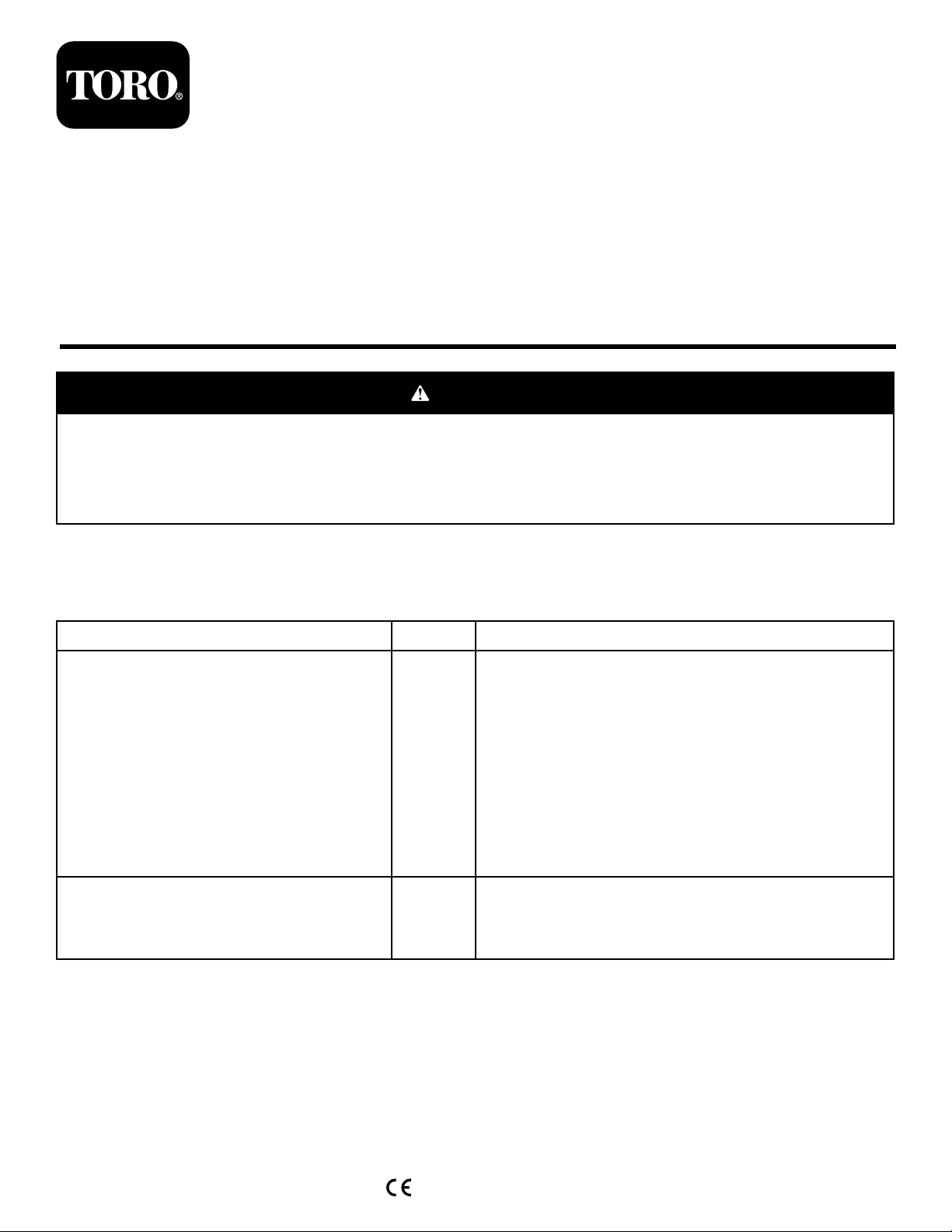
Figure1
1.Motor
2.Coupler4.Stake
5.Removetheexistingstakes.
6.Removetheexistingcouplersandinstallthenew
couplersusing8bolts(M12-13/4x80mm),8locknuts
(M12),and2greasettings(Figure2).
3.PinandO-ring(pinand
e-clipon4045)
Figure3
1.Coupler3.O-ring
2.Pin
Ifyourmachinehasacage,installthecageassemblyandlatch
thecagedoor.
4.Stake
Figure2
1.Greasetting3.Locknut(M12)
2.Bolt(M12)4.Coupler
2
Page 3

InstallingtheRockStakesonthe2024
DirectionalDrill
1.Securethestakeguideontotheguideringusingthe8
bolts(M8)(BoxAofFigure4).
InstallingtheStakesonthe
4045DirectionalDrill
PreparingtheMachineandRemoving
theCurrentStakes
Note:Having2peopleoraliftingmechanismmakesiteasier
toinstallthestakes.
1.Positionthethrustframe25.4cm(12inches)offthe
ground,withthestakesintheupposition.
2.Turnofftheengineandthebatterydisconnectswitch.
3.Supportthefootwithajackstandorequivalent.
4.Ifyourmachinehasacage,unlatchandopenthe
stake-downcagedoor.
5.Whileholdingthestakes,removethepinsande-clips
securingthestakestothemotors(Figure1).
6.Removetheexistingstakes.
InstallingtheDirtStakesonthe4045
DirectionalDrill
Figure4
1.Bolts(M8)3.Guidering
2.Stakeguide
2.Placetheassemblyintotheholeofthethrustframe
foot.
3.Aligntheboltheadssothattheyaresquarewiththe
foot.
4.Weldtheguideringontothemachineusing7equally
spaced5cmby0.64cm(2inchby0.25inch)weldsas
showninBoxBofFigure4.
5.Removetheboltsandstakeguide(BoxCofFigure4).
6.Painttheweldedareawithblackpaint.
7.Placethestakeguideonthestakeandguidethestake
intotheguideringonthemachine(BoxDofFigure4).
8.Installthenewstakesbyaligningtheholeinthestake
withtheholeinthemotorcouplerandsecureitwith
theO-ringsandpinsincludedinthiskit(Figure3).
9.Securethestake-guideringontheweldedguidering
usingthe8bolts(M8-11/4x20mm)(Figure4).
10.Torquetheboltsto23to29N-m(17to21ft-lb).
Installthenewstakesbyaligningtheholeinthestakewith
theholeinthemotorandsecureitwiththepinsande-clips
previouslyremoved(Figure5).
Figure5
Rockstakesshownforillustrativepurposesonly
1.Coupler3.Stake
2.Pin
3
Page 4

InstallingtheRockStakesonthe4045
DirectionalDrill
Have2peopleperformthisprocedure.
1.Slidethestakeguideoverthetopoftherockstakeand
placethestakeonthemachineasshowninFigure6.
Note:Have1personholdthestakeinplacewhilethe
otherpersoncontinuesthisprocedure.
Figure8
1.Stakeguide
4.TorquetheM10boltsto73to89N-m(54to66ft-lb).
5.SecurethestaketothemotorasshowninFigure5.
6.Ifyourmachinehasacage,closeandlatchthecage
door.
Important:Removetheguideringfromthefootwhen
switchingfromtherockstakestothedirtstakes.
Figure6
2.Looselysecurethestakeguidetotheguideringbase
usingthe6Bolts(M10-11/2x25mm)asshownin
Figure7.
Figure7
1.Bolts(M10)
3.Insertthestakeguidefromundertheplatform(Figure
8)andtightenthebolts.
4
 Loading...