

Page 1
StakeDownGuards
4045DirectionalDrill
ModelNo.23807
ModelNo.23807E
ThisproductcontainsachemicalorchemicalsknowntotheStateofCaliforniato
causecancer,birthdefects,orreproductiveharm.
Safety
SafetyandInstructionalDecals
FormNo.3396-148RevB
InstallationInstructions
WARNING
CALIFORNIA
Proposition65Warning
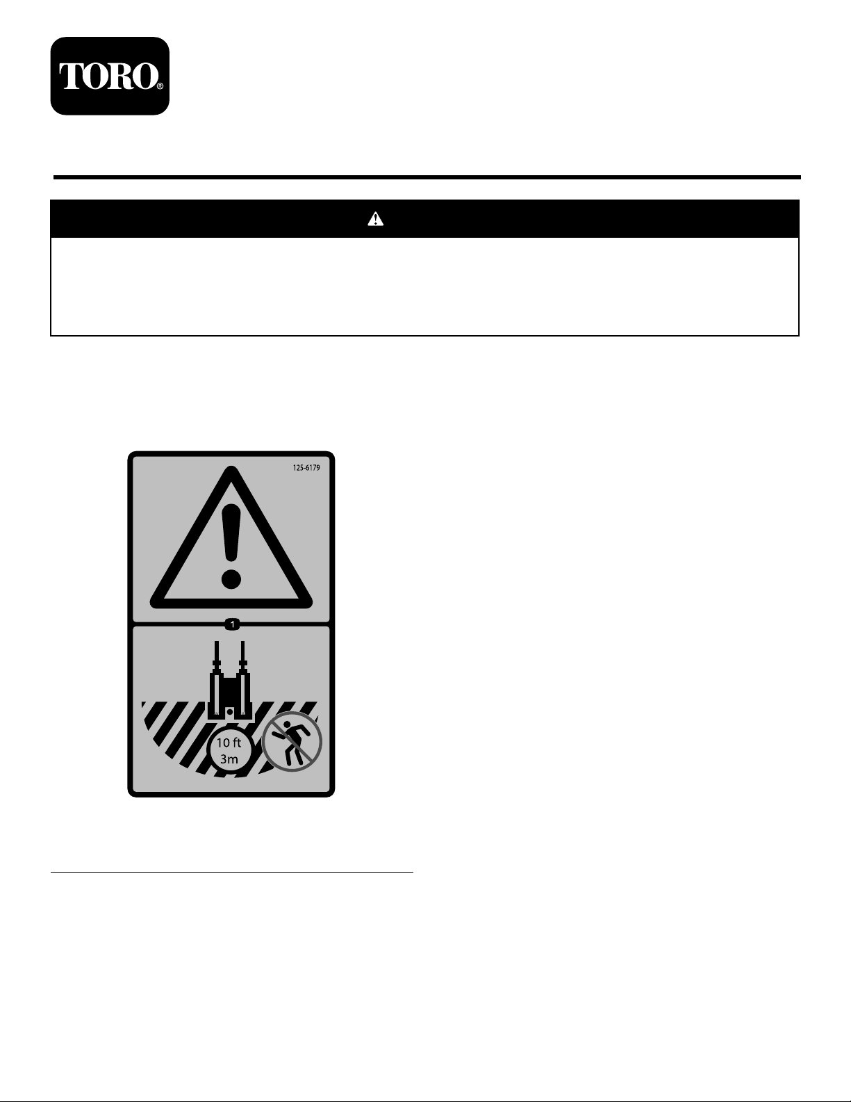
125-6179
1.Warning—hazardarea;keepatleast3meters(10feet)
awayfromthemachinewhileinoperation.
©2015—TheToro®Company
8111LyndaleAvenueSouth
Bloomington,MN55420
Registeratwww.T oro.com.
OriginalInstructions(EN)
PrintedintheUSA
AllRightsReserved
*3396-148*B
Page 2
1
PreparingtheMachineand InstallingtheLeftGuard
Partsneededforthisprocedure:
1Proximity-sensorcap
1
Guardcover
1
Guard-supportbracket
6U-nut
6
Bolt(M8-11/4x35mm)
1
Leftguard
1
Bolt(M12-13/4x120mm)
1
Locknut(M12)
1
Bolt(M8-11/4x30mm)
1
Locknut(M8)
Procedure
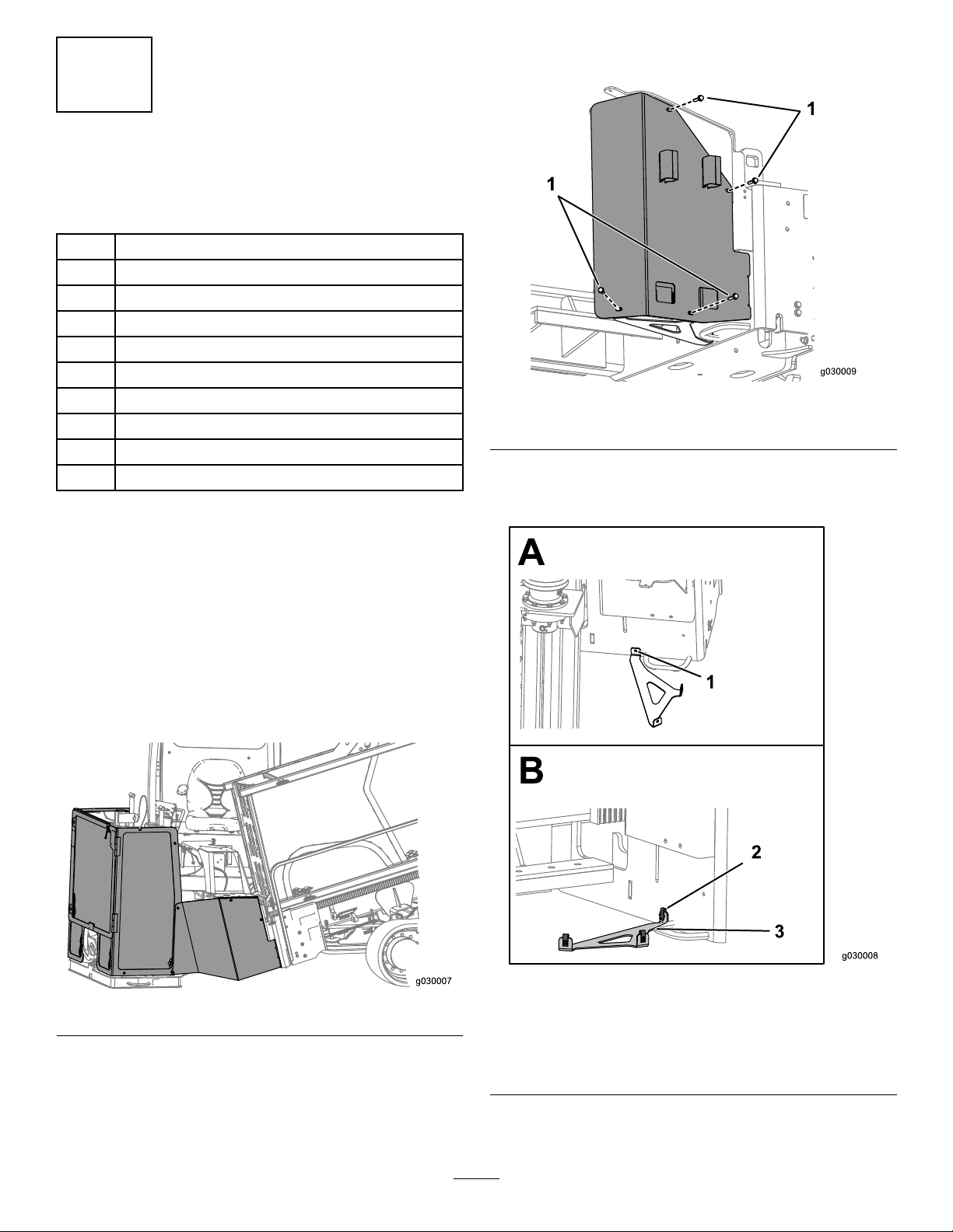
8.Looselyinstalltheassemblytotheframeusing5bolts
(M8-11/4x35mm)asshowninFigure2.
Figure2
1.Bolts(M8-11/4x35mm)
9.Usingtheguard-supportbracketasaguide,markthe
locationofwheretodrillaholeintotheframe(Figure
2).
1.Disconnecttheproximitysensorthatisconnectedto
thedooronthecage.
2.Gatherupthewiringharnesswiththesensorandusea
cabletietosecuretheharnesstothemachine.
3.Connecttheproximitysensorcaptotheendofthe
wiringharnessconnection.
4.Removethedoor,cageassembly ,andleftguard(Figure
1).
Figure1
Figure3
Guard-supportbracketshownwithoutguardcoverfor
illustrativepurposesonly
5.Place3U-nutsontheguard-supportbracket(Figure3).
6.Installtheguard-supportbracketontotheguardcover
(Figure2).
7.Place3U-nutsontheguardcover.
1.Drillholehere
2.U-nut
10.Removetheguardassemblyanddrilltheholeintothe
frame.
2
3.Guard-supportbracket
Page 3
11.Installtheguardassemblyontotheframe(Figure2)
1
g0304 32
using6bolts(M8-11/4x35mm).
12.Torquetheboltsto23to29N-m(17to21ft-lb).
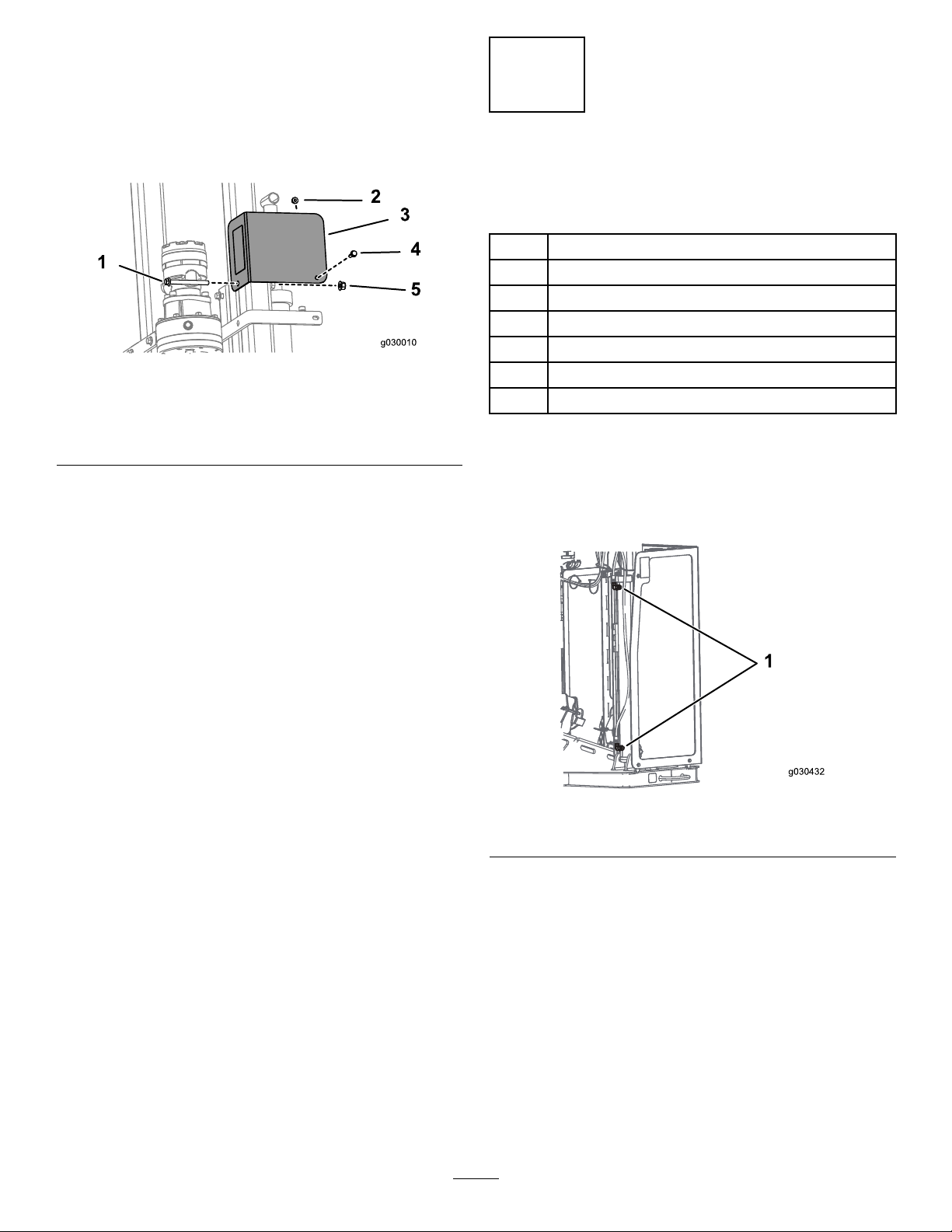
13.Installtheleftguardassemblyusing1bolt(M8-11/4x
30mm),1locknut(M8),1Bolt(M12-13/4x120mm),
and1locknut(M12)asshowninFigure4.
Figure4
1.Bolt(M12-13/4x120mm)4.Bolt(M8-11/4x30mm)
2.Locknut(M8)5.Locknut(M12)
3.Leftguardassembly
14.TorquetheM8boltsto23to29N-m(17to21ft-lb).
15.TorquetheM12boltsto80to100N-m(59to73ft-lb).
2
InstallingtheRightGuard Brackets
Partsneededforthisprocedure:
1Upperbracket,large
2
Bolt(M12-13/4x120mm)
2
Locknut(M12)
1Upperbracket,small
1Lowerbracket
4
Bolt(M8-11/4x30mm)
4
Locknut(M8)
Procedure
1.Rotatethehydrauliclinesasneededtoensurethatthey
donotrubonthestakedownguardassemblies(Figure
5).
Figure5
1.Hydraulicttings/lines
2.InstalltheuppersupportbracketsasshowninFigure6.
3
Page 4
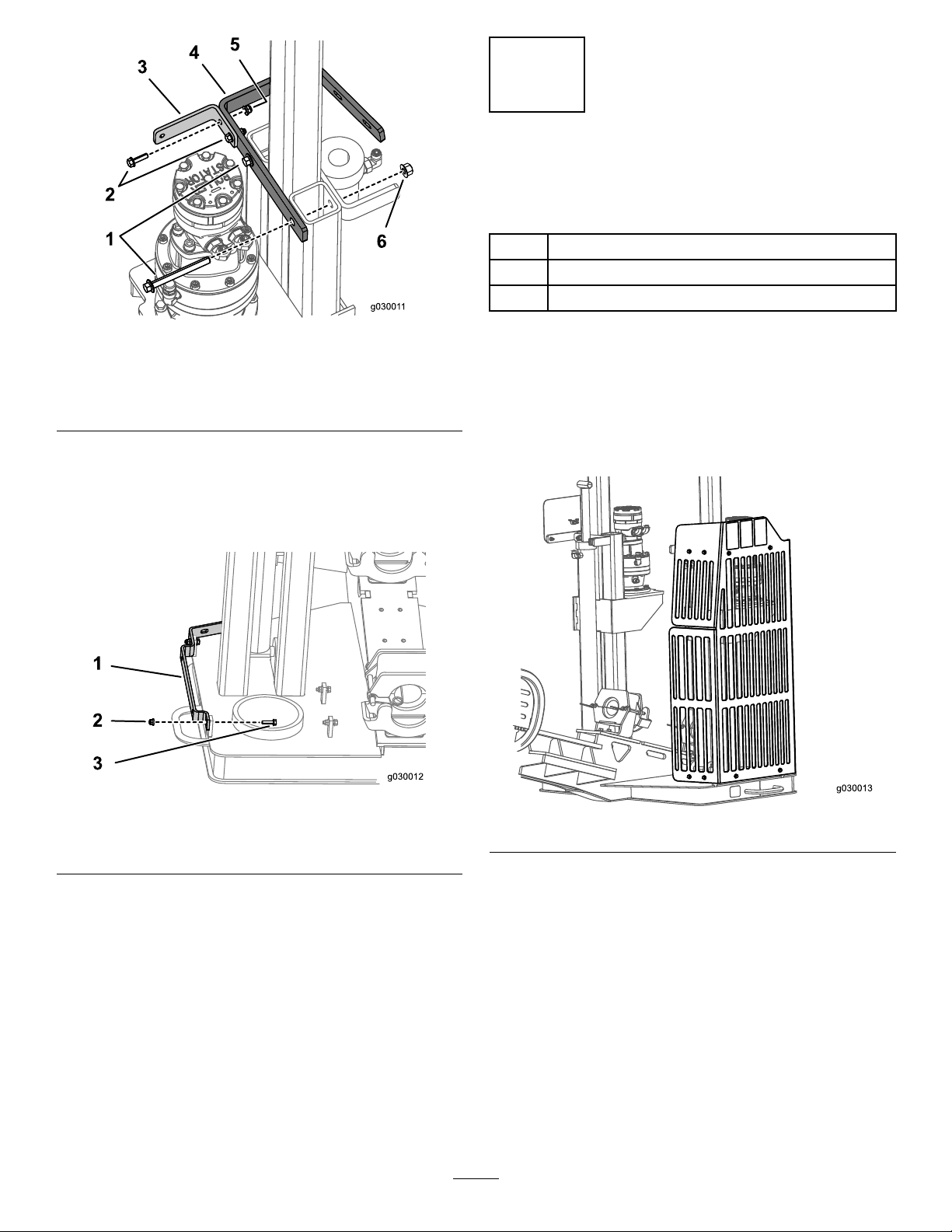
Figure6
1.Bolt(M12-13/4x120mm)
2.Bolt(M8-11/4x30mm)5.Locknut(M8)
3.Upperbracket,small
3.TorquetheM8boltsto23to29N-m(17to21ft-lb).
4.TorquetheM12boltsto80to100N-m(59to73ft-lb).
5.Installthelowerbracketusing2bolts(M8-11/4x30
mm)and2locknuts(M8)asshowninFigure7.
4.Upperbracket,large
6.Locknut(M12)
3
InstallingtheStakedown Guard
Partsneededforthisprocedure:
1
Stakedownguard
8
Bolt(M8-11/4x30mm)
8
Locknut(M8)
Procedure
Rotatethehydrauliclinesasneededtoensurethatthey
donotrubonthestakedownguardassemblies.
Installthestakedownguardusing8bolts(M8-11/4x25mm)
and8locknuts(M8)asshowninFigure8.
Figure7
1.Lowerbracket
2.Locknuts(M8)
6.TorquetheM8boltsto23to29N-m(17to21ft-lb).
3.Bolts(M8-11/4x30mm)
Figure8
Torquetheboltsto23to29N-m(17to21ft-lb).
4
 Loading...