

Page 1
FormNo.3396-143RevB
StakeDownGuards
2024DirectionalDrill
ModelNo.23805
ModelNo.23805E
InstallationInstructions
WARNING
CALIFORNIA
Proposition65Warning
ThisproductcontainsachemicalorchemicalsknowntotheStateofCaliforniato
causecancer,birthdefects,orreproductiveharm.
Safety
SafetyandInstructional
Decals
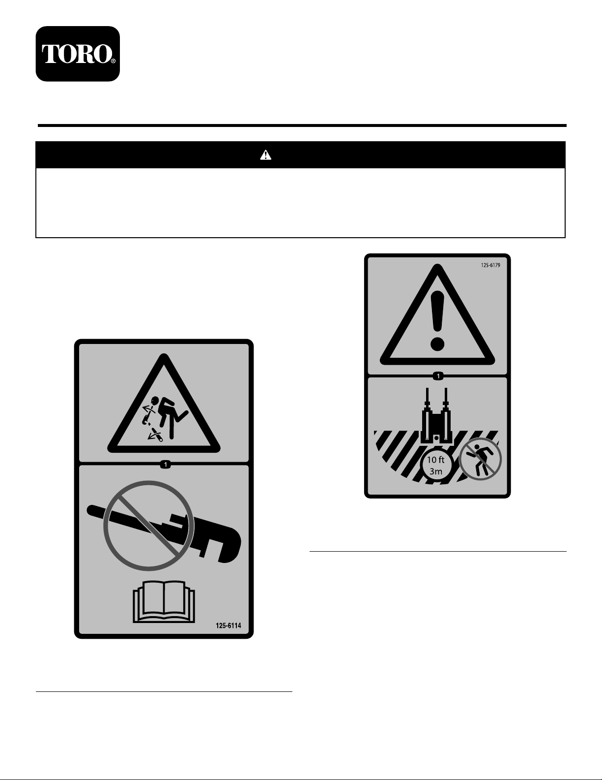
125-6179
1.Warning—hazardarea;keepatleast3meters(10feet)
awayfromthemachinewhileinoperation.
125-6114
1.Storedenergyhazard—donotusetools;readthe
Operator’sManual.
©2015—TheToro®Company
8111LyndaleAvenueSouth
Bloomington,MN55420
Registeratwww.T oro.com.
OriginalInstructions(EN)
PrintedintheUSA
AllRightsReserved
*3396-143*B
Page 2
1
PreparingtheMachineand InstallingtheLeftGuard
Partsneededforthisprocedure:
1Proximity-sensorcap
1
Bolt(M8-11/4x30mm)
1
Locknut(M8)
1
Locknut(M12)
1
Bolt(M12-13/4x80mm)
1
Left-guardassembly
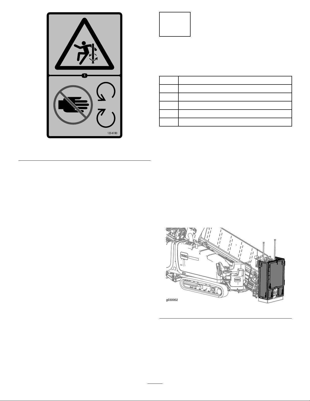
125-6180
1.Entanglementhazard—keepawayfrommovingparts.
Procedure
1.Parkthemachineonalevelsurfaceandremovethekey.
Note:Placethestakedowncylindersintheextended
position.
2.Disconnectthesensorthatisconnectedtothedoor
onthecage.
3.Gatherupthewiringharnesswiththesensorandusea
cabletietosecuretheharnesstothemachine.
4.Connecttheproximity-sensorcaptotheendofthe
wiringharnessconnection.
5.Removethedoorandcageassembly(Figure1).
Figure1
6.Loosenandrotatethehydraulicttingsonthewrench
assembliessothatitdoesnotinterferewiththeguard
assemblies(Figure2).
2
Page 3

g0300 79
Figure2
7.Tightenthettings.
8.Installtheleft-guardassemblyusing1bolt(M8-11/4x
30mm),1locknut(M8),1bolt(M12-13/4x80mm),
and1locknut(M12)asshowninFigure3.
2
InstallingtheRightGuard Brackets
Partsneededforthisprocedure:
2
Locknut(M12)
2
Bolt(M12-13/4x80mm)
1Largeupperbracket
1
Smallupperbracket
1Lowerbracket
4
Bolt(M8-11/4x30mm)
4
Locknut(M8)
Procedure
1.InstalltheuppersupportbracketsasshowninFigure4.
Figure3
1.Bolt(M12-13/4x80mm)3.Locknut(M8)
2.Locknut(M12)4.Bolt(M8-11/4x30mm)
9.TorquetheM8boltsto23to29N-m(17to21ft-lb).
10.TorquetheM12boltsto80to100N-m(59to73ft-lb).
Figure4
1.Bolt(M12-13/4x80mm)
2.Locknut(M8)5.Bolt(M8-11/4x30mm)
3.Upperbracket,small
2.TorquetheM8boltsto23to29N-m(17to21ft-lb).
3.TorquetheM12boltsto80to100N-m(59to73ft-lb).
4.Installthelowerbracketusing2bolts(M8-11/4x30
mm)and2locknuts(M8)asshowninFigure5.
4.Upperbracket,large
6.Locknut(M12)
3
Page 4

Figure5
1.Bolts(M8-11/4x30mm)
5.TorquetheM8boltsto23to29N-m(17to21ft-lb).
3
InstallingtheStakedown Guard
Partsneededforthisprocedure:
1
Stakedownguard
5
Bolt(M8-11/4x25mm)
5
Locknut(M8)
Procedure
Installthestakedownguardusing5bolts(M8-11/4x25mm)
and5locknuts(M8)asshowninFigure6.
Figure6
1.Bolts(M8-11/4x25mm)
TorquetheM8boltsto23to29N-m(17to21ft-lb).
4
 Loading...