

Page 1
FormNo.3414-738RevA
2226DirectionalDrill
ModelNo.23803—SerialNo.400000000andUp
SoftwareGuide
Readthisinformationcarefullytolearnhowtooperateandmaintainyourproductproperlyandtoavoidinjury
andproductdamage.Y ouareresponsibleforoperatingtheproductproperlyandsafely.ReadyourOperator’s
Manualformoreinformation.
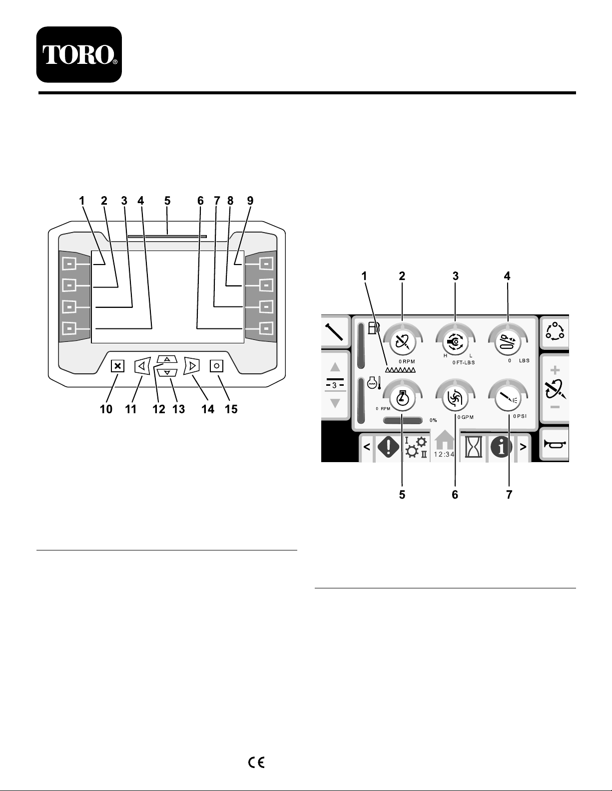
DisplayScreenButtons
Figure1
1.Button19.Button5
2.Button210.Escapebutton
3.Button3
4.Button412.Uparrowbutton
5.Statusbar
6.Button814.Rightarrowbutton
7.Button7
8.Button6
11.Leftarrowbutton
13.Downarrowbutton
15.OKbutton
HomeScreenOptions
MainInformationScreen
Thisistherstscreenthatappearsaftertheinitial
splashscreen.Tonavigatebetweenscreens,usethe
leftandrightarrows.
g238407
g236822
Figure2
1.Carriageindicator5.Enginespeed(rpm)
2.Drillspeed(rpm)6.Drilling-uidowrate
3.Rotarytorque
4.Thrustforce
7.Drilling-uidpressure
©2017—TheT oro®Company
8111LyndaleAvenueSouth
Bloomington,MN55420
Registeratwww.Toro.com.
OriginalInstructions(EN)
PrintedintheUSA
AllRightsReserved
*3414-738*A
Page 2
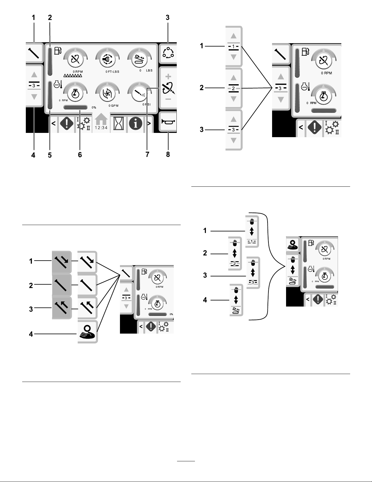
Figure3
1.Pipefunctions
2.Fuelgauge6.Engineload
3.Limitsettingoptions
4.Selectpiperow
5.Enginetemperaturegauge
7.Thrustforce,drillspeed
(rpm),orrotarytorque
adjustment
8.Horn
Pushbuttons2and3toswitchchoosearow.
g236827
g236823
Figure5
1.Row13.Row3
2.Row2
Inmanualpipeloadingmode,usebuttons2and3to
choosearowortoloadthepipetothedrillstring.
Pushbutton1toswitchbetweenthepipefunctions:
pullpipe,pushpipe,neutral,ormanualpipeloading.
Figure4
1.Pushpipe3.Pullpipe
2.Neutral4.Manualpipeloading
g236825
Figure6
ManualPipeLoadingOptions
g236826
1.Row13.Row3
2.Row24.Loadthepipetothedrill
string
2
Page 3
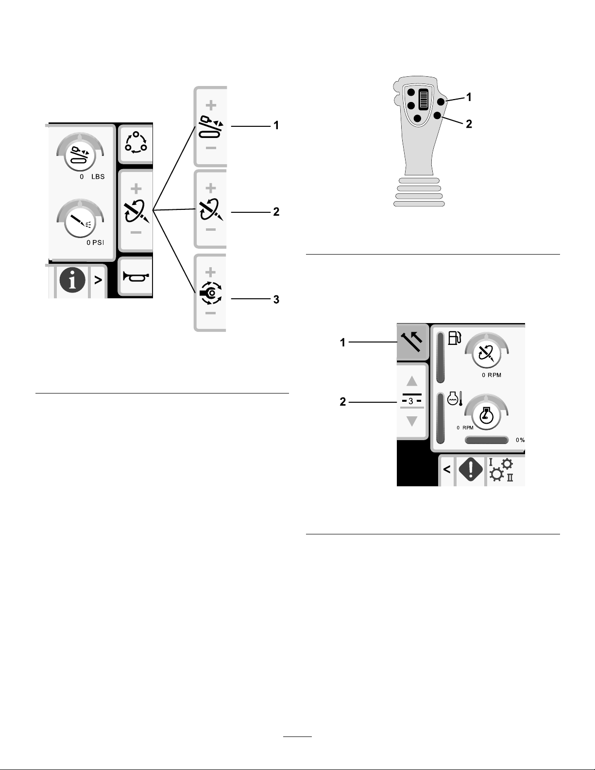
Pushbutton5toswitchbetweenthrustforce,drill
speed(rpm),androtarytorque.
Usebuttons6and7tosetlimitsforthedrillspeed
(rpm),rotarytorque,andthrustforce.
PullingPipeinSmartTouchMode
StarttheSmartT ouchmodewiththecamassembly
intheparkposition.
g236957
Figure8
1.Gotothepreviousstep2.Gotothenextstep
1.Pushbutton1toselectthepullpipeoption
(Figure9).
2.Pushbuttons2and3toselecttherowwhere
youwanttoplacethepipe(Figure9).
Figure7
1.Thrustforce
2.Drillspeed(rpm)
3.Rotarytorque
SmartTouch™Home Screen
SmartTouchmodeallowstheoperatortoloadand
unloadpipesfromthepipeboxwithlessjoystick
operationtoreduceoperatorfatigue.
UsetheCarriageSettingsScreen(page12)toturn
SmartTouchmodeonandoff.
Note:ThePush/PullIconhasagreenbackground
whenSmartTouchmodeisonandaribbonappears
atthebottomofthescreenshowingasequenceof
thesteps.
Important:NeverswitchbetweenPush/Pull
modesduringthechosenoperation.Useneutral
(manual)modetoswitchbetweenPush/Pull;refer
toCarriageSettingsScreen(page12)toturn
SmartTouchmodeoff.
g236824
g238157
Figure9
1.Pullpipe
2.Selectpiperow
3
Page 4

3.Holdthelowerrightbuttonontheleftjoystick
(Figure8)untiltheelevatorlowers,thecam
assemblyrotatestowardtheoperatorstation,
andthearmsfullyextend(Figure11).
Figure10
4.Releasethebuttontoproceedtothenextstep
inthesequence(Figure12).
g236959
Figure12
g236958
5.Breakthepipeconnection;refertoRemoving
DrillPipesintheOperator’sManual.
6.Holdthelowerleftbuttonontheleftjoystick
togripthepipe(Figure13andFigure14)and
releasethebutton.
Figure11
g238156
Figure13
g210519
Figure14
g239743
4
Page 5
7.Holdthelowerrightbuttonontheleftjoystick
(Figure8)untilthearmsfullyretract(Figure16).
10.Releasethebuttontoproceedtothenextstep
inthesequence(Figure19).
Figure15
Figure16
8.Releasethebuttontoproceedtothenextstep
inthesequence(Figure17).
g236960
g236962
Figure19
11.Holdthelowerrightbuttonontheleftjoystick
(Figure8)untiltheelevatorputsthepipeback
inthepipeboxandthecamrotatestothehome
position(Figure20).
g210521
Figure17
9.Holdthelowerrightbuttonontheleftjoystick
(Figure8)untilthecamassemblyrotatestothe
selectedrowunderthepipebox(Figure18).
Figure18
g236961
g210525
Figure20
12.Releasethebuttontostartthepull-pipeprocess
again.
g210523
5
Page 6
PushingPipeinSmartTouchMode
StarttheSmartT ouchmodewiththecamassembly
intheparkposition.
Figure21
g210463
Figure24
g236957
1.Gotothepreviousstep2.Gotothenextstep
1.Pushbutton1toselectpushpipe(Figure22).
2.Pushbuttons2and3toselecttherowwhere
youwanttogetthepipe(Figure22).
Figure22
1.Pushpipe
2.Selectpiperow
4.Releasethebuttontoproceedtothenextstep
inthesequence(Figure25).
g236964
Figure25
5.Holdthelowerrightbuttonontheleftjoystick
(Figure21)untilthecamassemblyfullyrotates
forwardtotherackandtheelevatorsliftthe
remainingpipeintothepipebox(Figure26).
g238158
3.Holdthelowerrightbuttonontheleftjoystick
(Figure21)untilthecamassemblyrotatesto
theselectedrowandthepipelowersintothe
opening(Figure24).
Figure23
g210465
Figure26
g236963
6
Page 7

6.Releasethebuttontoproceedtothenextstep
inthesequence(Figure27).
Figure27
7.Holdthelowerrightbuttonontheleftjoystick
(Figure21)untilthearmsextend(Figure28).
g236965
g238411
Figure31
11.Holdthelowerrightbuttonontheleftjoystick
(Figure21)untilthearmsretractandthecam
assemblyreturnstothehomeposition(row3)
(Figure33).
Figure28
8.Releasethebuttontoproceedtothenextstep
inthesequence(Figure29).
Figure29
9.Makethepipeconnection;refertoAddingDrill
PipesintheOperator’sManual.
10.Holdthelowerleftbuttonontheleftjoystick
(Figure30)toreleasethepipe(Figure31)and
releasethebutton.
g236967
Figure32
g210528
g236966
Figure30
g238409
Figure33
12.Releasethebuttontostartthepush-pipe
processagain.Thecamassemblygoesto
g238156
therowpickedinstep2ofPushingPipein
SmartTouchMode(page6).
7
Page 8
ManualPipeLoading
Manualpipeloadingmodeallowstheoperatorstoloadandunloadpipesfromthecamassemblywhenitis
rotatedoutsidethepipebox.
Note:Use2peopletoloadthepipesintothecamassembly.
Figure34
1.Setthemachinetomanualpipeloadingmode;refertoCarriageSettingsScreen(page12)..
g238408
2.Usebuttons2and3tochoosewhereyouwantthepipetobeplaced;aroworthedrillstring(Figure35).
Figure35
g238311
8
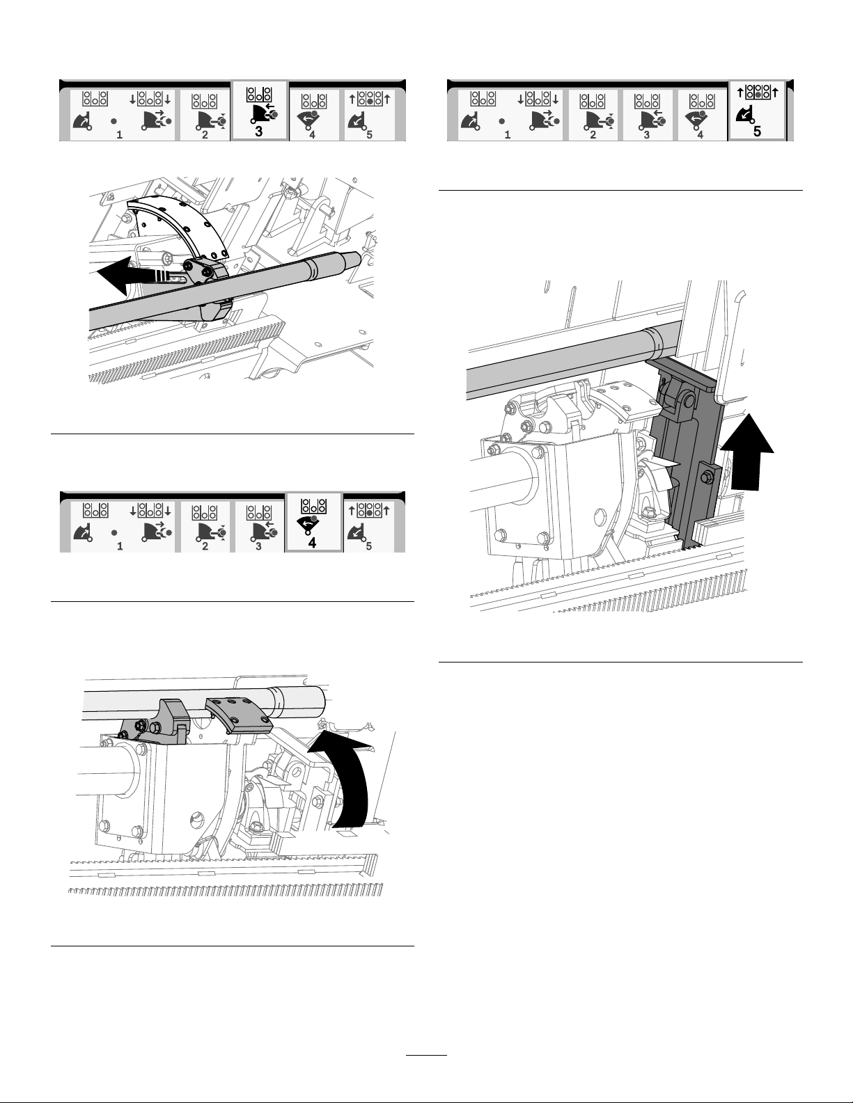
Page 9

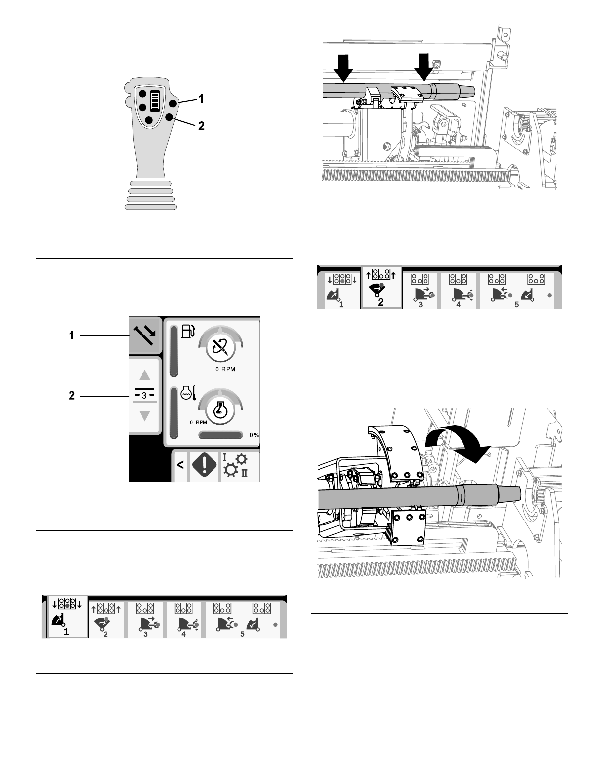
3.Raisetheelevator(Figure36).
4.PushthecamrotatedialUPtorotatethecamassemblyoutsideofthepipebox(Figure36).
5.Raisethepipeloadingguard(Figure36).
Figure36
6.Use2peopletoloadapipeintothecamassembly(Figure37).
7.Lowerthepipeloadingguard(Figure37).
g238263
Figure37
g238264
9
Page 10

8.Lowertheelevator(Figure38).
9.PushthecamrotatedialDOWNtorotatethecamassemblytothelocationpickedinstep2(Figure38).
Figure38
10.Loadingtothedrillstringonly:RefertoAddingDrillPipesintheOperator’sManual.
11.Repeatsteps3to9tocontinueloadingpipestothepipebox.
g238312
HoursScreenOptions
MachineHoursScreen
Toaccessthisscreenpushbutton1ontheHours
screen.
Thisscreenshowstheoperatinghoursofthe
machine.Machine1cannotbechanged.Machine
2canbereset.
Button5switchesbetweenmachine1andmachine2.
Button6resetsthedailymachinehours.
DrillingFluid(Mud)UseScreen
Toaccessthisscreenpushbutton2ontheHours
screen.
Thisscreenshowsthedrillinguid(mud)useofthe
machine.T otaldrillinguid(mud)cannotbechanged.
Dailydrillinguid(mud)canbereset.
Button5switchesbetweenmuduse1andmuduse2.
Button6resetsthedailymuduse.
g236834
Figure40
Figure39
g236833
10
Page 11

MaintenanceScheduleScreens
Toaccessthisscreen,pushbutton3ontheHours
screen.
Thesescreensprovidetheuserwiththedaily
maintenanceschedulesandthe50-hour,250-hour,
400-hour,and800-hourincrements.
Toresetthemaintenanceinterval,referto
MaintenancePINScreen(page13).
Pushthefollowingbuttonstoviewthefollowing
maintenanceschedules:
•Button3—Dailymaintenanceschedule(Figure41)
•Button5—50-hourmaintenanceschedule(Figure
42)
•Button6—250-hourmaintenanceschedule(Figure
43)
•Button7—400-hourmaintenanceschedule(Figure
44)
•Button8—800-hourmaintenanceschedule(Figure
45)
g236829
Figure43
g240193
Figure44
Figure41
Figure42
g236832
g240194
Figure45
g236830
11
Page 12

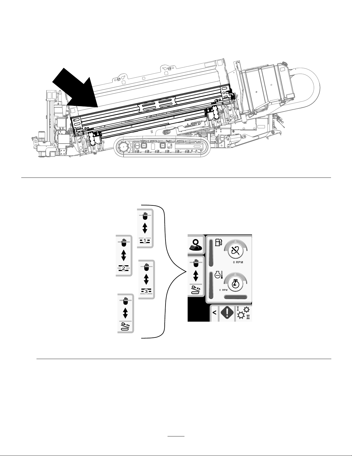
SettingsScreenOptions
CarriageSettingsScreen
Pushbutton1ontheSettingsscreen.
Usethisscreentochangethecarriagesettings.Push
theOKbuttontoswitchbetweenSmartTouchandthe
manualpipeloaderoption.
Usetheupanddownarrowstochoosethepush,pull,
orneutralsetting.
Figure46
ControlModeScreen
Pushbutton2ontheSettingsscreen.
Usethisscreentoselectbetweenthe2joystick
controloptions.Pushtheupanddownbuttonsto
switchbetweenModeIandModeII.
g236982
Figure47
•ModeI—Therightjoystickcontrolsthethrust
andtherotationfunctions.RefertoFigure59
g236980
ontheJoystickHelpScreen(page16)formore
information.
PushPipe:refertoStartingtheFirstPipeandAdding
DrillPipesintheDrillingtheBoresectioninyour
Operator’sManualforfullinstructions.
PullPipe:refertoRemovingDrillPipesintheDrilling
theBoresectioninyourOperator’sManualforfull
instructions.
ManualPipeLoader:refertoManualPipeLoading
(page8).
•ModeII—Therightjoystickcontrolsthethrust
functions.Theleftjoystickcontrolstherotation
functions.RefertoFigure60ontheJoystickHelp
Screen(page16)formoreinformation.
12
Page 13

MaintenanceOptionsScreen
MaintenancePINScreen
Pushbutton3ontheSettingsscreen.
Pushtheupanddownarrowstoswitchbetween
MaintenanceandParameters.
TheMaintenancepinnumberis12356.
Figure48
LanguageandUnitsOptions Screen
Pushbutton5ontheSettingsscreentoaccessthe
screentoswitchbetweenEnglishandmetricunits.
Usetheupanddownarrowkeystochangethe
languageandunitoptions.
g236983
Figure49
g239956
ResettingtheMaintenanceIntervals
1.EnterthemaintenancePINandawait
conrmationofcorrectPINmessage.
2.PushtheOKbuttontostarttheresetprocess.
3.NavigatetotheMaintenanceScheduleScreens
(page1 1).
4.Selecttheintervalthatyouwanttoreset.
5.Pushtheintervalnumber2moretimestoreset
theinterval.
ScreenSettingsScreen
Pushbutton6ontheSettingsscreentocyclethrough
thedifferentadjustments.Usetheupanddown
arrowstoadjusttheparameters.
TheMainDrillingScreenzoomsintothedrilling
functions.Thesesettingsadjustthedelayonhow
longittakestozoom.
g236985
Figure50
13
Page 14

ClockSettingsScreen
Pushbutton7ontheSettingsscreentoswitch
betweentheclockoptions.Usetheupanddown
arrowstoadjusttheparameters.
Figure51
I/OScreens
•Thelowerlefticonindicatesiftheleftjoystickis
calibratedproperly.
•Thelowerrighticonindicatesiftherightjoystickis
calibratedproperly.
CalibratingtheJoysticks
Usethisscreentocheckthecalibrationofthe
joysticks.RefertoCalibratingtheTravelPendant
(page18)tocalibratethetravelpendant.
Thereddotisinthecenterofthetargetsshowsthe
movementoftheleftandrightjoysticks.Ifthereddot
doesnotreach±10,000,seeyourAuthorizedService
Dealertoserviceorreplaceyourjoystick.
g236981
JoystickI/OandCalibration Screen
JoystickI/OScreen
Pushbutton1ontheI/OscreentoaccesstheJoystick
I/Oscreen.
Figure52
•Therotaryvoltagerangesfrom0.0to8.5Vand
bepresentforeithermake(uppericon)orbreak
(lowericon)astheselectedrotaryjoystickis
moved.
g238476
Figure53
g237131
•Thecarriageindicatesarangefrom0.0to10.0
voltsinthejoystickselecteddirectionforthrustor
pullback.
14
Page 15

EngineI/OScreen
CamArmI/OandCalibration
Toaccessthisscreenpushbutton2ontheI/Oscreen.
Thisscreendisplaysengineinformation.
Figure54
1.Enginespeed(rpm)
2.Engineoilpressure
3.Airlterindicator7.Hydraulicuid
4.Enginecoolant
temperature
5.Batteryvoltage
6.Hydraulicuidlter
temperature
8.Hydraulicuidlevelislow
Screen
Toaccessthisscreenpushbutton3ontheI/Oscreen.
Usethisscreentocalibratethecamassembly .
Pushtheupanddownbuttonstoselecttheload
positionandthepipe-rowposition.
Pushbutton3totogglethecalibrationonandoff.
g237125
g238451
Figure55
Enginespeed(rpm):displays,instepsof100,the
enginespeed(rpm).
Engineoilpressure:displaystheengineoilicon.
Airlter:theairltericonisgreenunlessthelteris
pluggedthentheindicatorisred.
Enginetemperature:displaystheenginecoolant
temperature.Thetemperaturedropsto40°Fwhen
theengineisoff.
Batteryvoltage:displaysthebatteryvoltage.
Iftheengineisoff,thevoltageismeasuredbythe
Torocontroller.
Hydraulic-uidlter:thehydraulicuidltericonis
greenunlessthelterispluggedthentheindicator
isred.
Hydraulic-uidtemperature:displaysthehydraulic
uidtemperature.
Hydraulic-uidlevelislow:theiconisredwhenthe
hydraulicuidlevelislow
g238452
Figure56
Thevoltageonthebottomindicatesthecamraw
sensorvoltage.Thevoltagesrangefrom1.0to4.0V.
Anyvoltagehigherorlowerindicateseithersensor
failureorincorrectcalibration.
Theothervoltagesarethecalibratedvoltages.
PushtheOKbutton2timesonthedesiredpositionto
savethecalibration.
15
Page 16

JoystickHelpScreen
Toaccessthesescreenspushbutton4ontheI/O
screen.
Thesescreensshowthefunctionofeachjoystick
button.
Pushtheupanddownarrowstoscrollthroughthe
screens.
Figure57
g237129
Figure60
g237126
Figure58
g237130
Figure61
g237127
Figure59
g237128
16
Page 17

LeftJoystickI/OScreen
Toaccessthisscreenpushbutton5ontheI/Oscreen.
Pushthebuttonsonthejoysticksandensurethatthecorrespondingiconilluminates.
Figure62
RightJoystickI/OScreen
Toaccessthisscreenpushbutton6ontheI/Oscreen.
Pushthebuttonsonthejoysticksandensurethatthecorrespondingiconilluminates.
g237132
Figure63
g237133
17
Page 18

TravelPendantI/OandCalibration
EngineDPFI/OScreen
Screen
TravelPendantI/OScreen
Toaccessthisscreenpushbutton7ontheI/Oscreen.
Thetravelpendantscreenshowsthevoltageand
positionofthejoysticklocatedonthependant.
Figure64
CalibratingtheTravelPendant
Toaccessthisscreenpushbutton8ontheI/Oscreen.
g237124
Figure65
g237134
1.Manualregeneration6.Enginestopwarning
2.Regenerationinterlock
3.Highexhausttemperature8.Ashload
4.Inhibitregeneration9.Lastregeneration
5.Warningsymbol
7.Sootload
ServiceInterval:Every400hours
ThereddotisinthecenterofthetargetandtheFNR
(forward,neutral,reverse)andSteervoltageshows
2.5Vpriortoallowingthedrilltomove.Ifthereddot
travelsoutsideoftheoutermostblackring,serviceor
replacethependant.
Theindicatorstotherightandleftofthecircleshow
thedirectionofthetracktravel.Thevoltagesshow
arangefrom0to10.0V.
Manualregeneration(regen):Pushthedownarrow
tostartaregenerationcycle.
Regenerationinterlock:PushtheOKbuttontolock
themachineduringamanualregeneration.
Highexhausttemperature:Thisicondisplayswhen
theexhausttemperaturehigh.
Inhibitregeneration:Pushtheuparrowtopostpone
aregenerationcycle.
Warningsymbol:Thisicondisplayswhena
regenerationisdueorthereisanissuewiththeDPF.
Enginestopwarning:Thisicondisplayswhena
regenerationisrequired.Themachinedoesnot
functionuntiltheprocessiscompleted.
Sootload:Thisisthesootloadpercentage.Perform
aregenerationcyclewhenthesootloadisat50%
orabove.
Ashload:Thisistheashloadpercentage.Perform
aregenerationcyclewhentheashloadisat10%or
above.
Lastregeneration:Thisisthenumberofhourssince
thelastregenerationcycle.
18
Page 19

ErrorsandMachine
MachineInformationScreen
InformationScreens
DrillErrorsScreens
Toaccessthisscreenpushbutton1ontheErrorsand
MachineInformationscreen.
Thisscreendisplaysanydrillerrors.
Pushbuttons5topagethroughtheerrors.
Pushbutton6toresettheerrormessages.
Toaccessthisscreenpushbutton3ontheErrorsand
MachineInformationscreen.
Thisscreendisplaysthemachineinformation
includingthemodel,serialnumber,andsoftware
version.
g237123
Figure68
Figure66
EngineErrorsScreen
Toaccessthisscreenpushbutton2ontheErrorsand
MachineInformationscreen.
Thisscreendisplaysanyengineerrors.
Pushbuttons5topagethroughtheerrors.
Pushbutton6toresettheerrormessages.
g237122
Figure67
g237121
19
Page 20

MachineCANInformationScreen
Pushbutton4toaccessthisscreen.
Ifanyoftheseiconsarered,refertoyourServiceManual.
Figure69
g237120
20
Page 21

WarningIcons
WarningIconDescriptionResolution
CarriageCrash
PipeLoadingGuard
•Thecarriageisinthedrillarea
andyoutrytooperatethe
loaderarmorpipecamor
•Youtrytooperatethecarriage
whentheloaderarmorpipe
camisnotinthehomeposition
Thepipeloadingguardisnotinthe
loweredposition.
Toclearthiswarning,dothe
following:
•Movethecamassemblytothe
homepositionand/or
•Reversethecarriage
Lowerthepipeloadingguard.
CamVoltage
TravelPendant•Theoperatorpresenceswitch
Thecamvoltageisaboveorbelow
theminimumormaximumvalues.
isnotpressedwhentryingto
tramthemachineor
•Thependantthumbjoystickis
notcentered
Carriage
EngineAirFilter
ColdHydraulicOilThehydraulicoiliscolderthan4°C
Thesensoronthedrillcarriagehas
anerror.
Theairlterisrestricted.RefertotheOperator’sManualto
(40°F).
ChecktheCamArmI/Oand
CalibrationScreen(page15)and
calibratethecam.
•Releaseallofthebuttons
onthetravelpendant,hold
downtheoperatorpresence
switchandcontinuetotramthe
machine.
•Thetravelpendantrequires
service;contactyour
AuthorizedServiceDealer
•Inspectthewiresonthesensor.
•SeeyourAuthorizedService
Dealer.
servicetheairlter.
Noactionrequired.Theengine
rpmislimitedtonomorethan1100
rpm.
CoolHydraulicOil
HotHydraulicOilThehydraulicoilishotterthan93°C
LowHydraulicOil
StakeDownCage(CE
modelsonly)
Thehydraulicoiliscolderthan
15°C(60°F).
(200°F).
Thehydraulicoilislowandneeds
tobecheckedandlled.
Thestakedowncagedoorisnot
closed.
21
Noactionrequired.Theengine
rpmislimitedtonomorethan1800
rpm.
Noactionrequired.Theengine
rpmresumesnormaloperation
oncetheoiltemperatureisless
than82°C(180°F).
RefertotheOperator’sManualto
servicethehydraulicoil.
Closethestakedowncagedoor .
Page 22

Notes:
Page 23

Notes:
Page 24

 Loading...