

Page 1
FormNo.3414-730RevA
2226DirectionalDrill
ModelNo.23803—SerialNo.400000000andUp
Registeratwww.T oro.com.
OriginalInstructions(EN)
*3414-730*A
Page 2
WARNING
CALIFORNIA
Proposition65Warning
Thisproductcontainsachemical
orchemicalsknowntotheStateof
Californiatocausecancer,birthdefects,
orreproductiveharm.
Dieselengineexhaustandsomeofits
constituentsareknowntotheStateof
Californiatocausecancer,birthdefects,
andotherreproductiveharm.
g217463
Figure1
ItisaviolationofCaliforniaPublicResourceCode
Section4442or4443touseoroperatetheengineon
anyforest-covered,brush-covered,orgrass-covered
landunlesstheengineisequippedwithaspark
arrester,asdenedinSection4442,maintainedin
effectiveworkingorderortheengineisconstructed,
equipped,andmaintainedforthepreventionofre.
Introduction
Thismachineisadirectionaldrillintendedfor
undergrounddrillingandpullbackoperationforutility
linesincluding:electrical,gas,communication,
water,etc.Itisdesignedtooperateawidevariety
ofattachmentseachofwhichperformaspecialized
function.Thismachineistobeusedintemperatures
of17to37°C(0to100°F).
Beforestartingoroperatingthemachine,readthis
informationcarefullytolearnhowtooperateand
maintainyourproductproperlyandtoavoidinjuryand
productdamage.Y ouareresponsibleforoperating
theproductproperlyandsafely.
YoumaycontactTorodirectlyatwww.Toro.com
forproductsafetyandoperationtrainingmaterials,
accessoryinformation,helpndingadealer,orto
registeryourproduct.
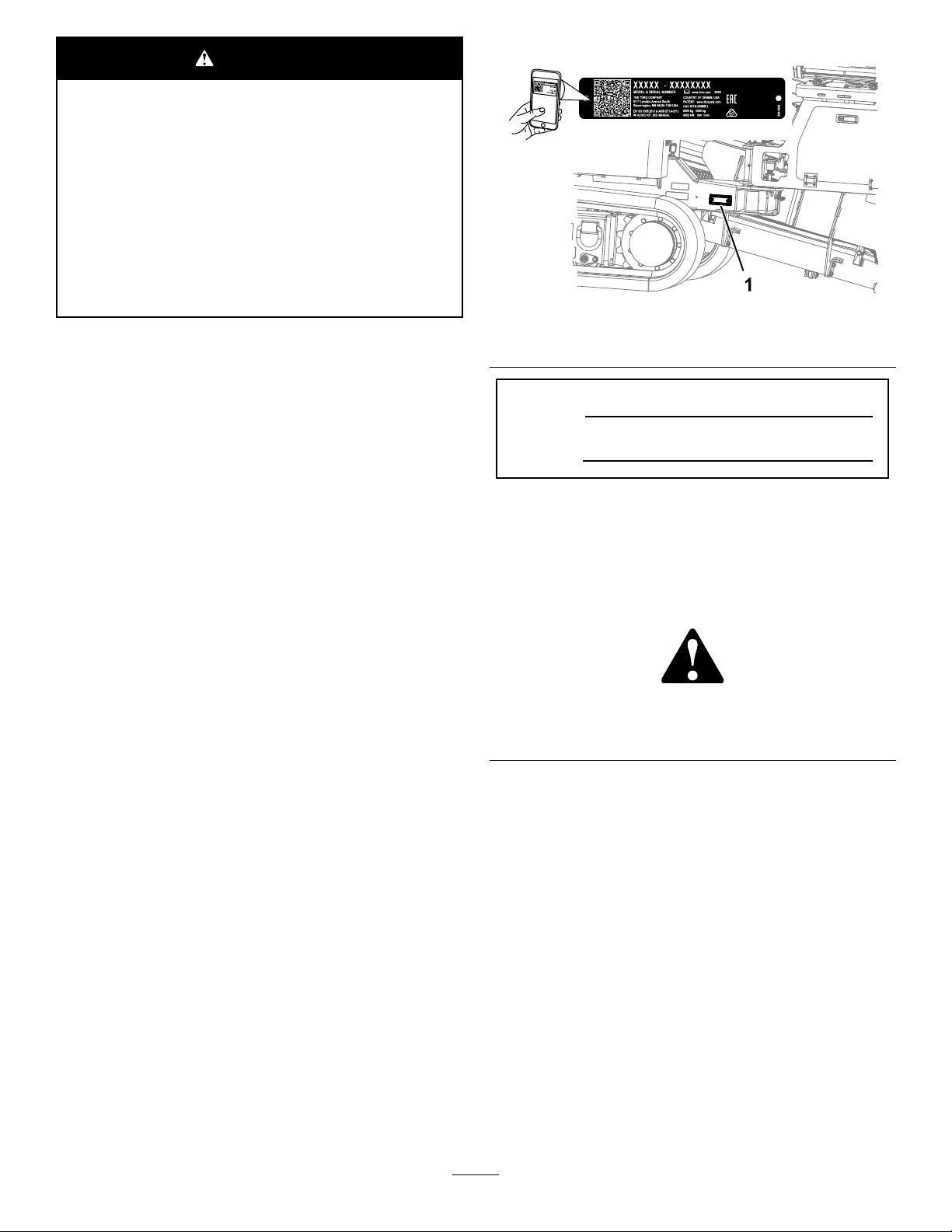
1.Modelandserialnumberlocation
ModelNo.
SerialNo.
Thismanualidentiespotentialhazardsandhas
safetymessagesidentiedbythesafetyalertsymbol
(Figure2),whichsignalsahazardthatmaycause
seriousinjuryordeathifyoudonotfollowthe
recommendedprecautions.
g000502
Figure2
1.Safetyalertsymbol
Thismanualuses2wordstohighlightinformation.
Importantcallsattentiontospecialmechanical
informationandNoteemphasizesgeneralinformation
worthyofspecialattention.
Wheneveryouneedservice,genuineToroparts,or
additionalinformation,contactanAuthorizedService
DealerorToroCustomerServiceandhavethemodel
andserialnumbersofyourproductready.Figure1
identiesthelocationofthemodelandserialnumbers
ontheproduct.Writethenumbersinthespace
provided.
©2017—TheToro®Company
8111LyndaleAvenueSouth
Bloomington,MN55420
Contactusatwww.Toro.com.
2
PrintedintheUSA
AllRightsReserved
Page 3

Contents
Safety.......................................................................4
GeneralSafety...................................................4
TrammingSafety................................................5
DrillingSafety.....................................................6
SafetyandInstructionalDecals..........................8
ProductOverview...................................................24
Controls...........................................................27
OperatorPlatform.........................................27
FrontControlPanel.......................................29
RearControlPanel........................................33
TravelPendant..............................................33
Specications..................................................34
BeforeOperation.................................................35
BeforeOperationSafety...................................35
UnderstandingHorizontalDirectional
Drilling...........................................................35
GatheringSiteInformation................................36
PlanningtheBorePath.....................................39
PreparingtheJobSiteandtheMachine
......................................................................44
MarkingandPreparingtheBorePath...............44
CheckingtheSafety-InterlockSwitches............44
TestingtheZap-AlertSystem............................45
MountingaFireExtinguisher............................46
LoadingtheDrillPipes......................................46
FillingtheFuelTank..........................................46
PerformingDailyMaintenance..........................47
StartingandShuttingOfftheEngine.................47
TrammingtheMachine.....................................48
LoadingandUnloadingtheMachine.................48
SettingUptheDrillHeadandTracking
System..........................................................50
SettinguptheMachineforDrilling.....................51
DeployingtheZap-AlertSystem.......................51
LoweringtheStakes.........................................52
ConnectingtoaDrilling-FluidSource................52
DuringOperation.................................................54
DuringOperationSafety...................................54
DieselParticulateFilterRegeneration...............55
DrillingtheBore................................................57
BackreamingandPullback...............................60
AfterOperation....................................................62
AfterOperationSafety......................................62
FinishingtheJob..............................................63
UsingtheTJCApplicator..................................63
MovingaDisabledMachine..............................64
Maintenance...........................................................65
RecommendedMaintenanceSchedule(s)...........65
Pre-MaintenanceProcedures..............................67
Pre-MaintenanceSafety...................................67
AccessingInternalComponents.......................67
UsingtheCylinderLock....................................68
Lubrication..........................................................68
GreasingtheMachine.......................................68
EngineMaintenance...........................................72
EngineSafety...................................................72
ServicingtheAirCleaner..................................72
ServicingtheEngineOil....................................74
AdjustingtheEngine-ValveClearance..............76
CleaningtheEngineEGRCooler......................76
InspectingtheEngineCrankcase-Breather
System..........................................................76
CheckingandReplacingFuelHosesand
Engine-CoolantHoses..................................76
LappingorAdjustingtheEngineIntakeand
ExhaustValves.............................................76
InspectingandCleaning
Engine-Emission-ControlComponents
andTurbocharger.........................................77
FuelSystemMaintenance...................................77
ServicingtheFuelSystem................................77
ServicingtheWaterSeparator.........................77
ReplacingtheFuelFilterElement.....................78
ElectricalSystemMaintenance...........................79
BatterySafety...................................................79
ServicingtheBattery.........................................79
ChargingtheBattery.........................................80
Jump-StartingtheMachine...............................80
DriveSystemMaintenance..................................81
CheckingthePlanetaryDriveOilLevel
PlanetaryDrive.............................................81
ChangingthePlanetaryDriveOil.....................82
CheckingtheRotaryGearboxDrive
Oil.................................................................82
ChangingtheRotaryGearboxDrive
Oil.................................................................83
ServicingtheTracks.........................................84
CoolingSystemMaintenance..............................85
CoolingSystemSafety.....................................85
CheckingtheCoolantLevelinthe
Reservoir......................................................85
CheckingtheCoolantLevelinthe
Radiator........................................................86
CheckingtheConditionofthe
Cooling-SystemComponents.......................86
CheckingtheConcentrationofthe
Coolant.........................................................86
CleaningtheCoolingSystem............................87
BeltMaintenance................................................89
ServicingtheEngine-DriveBelt........................89
HydraulicSystemMaintenance...........................90
HydraulicSystemSafety...................................90
ServicingtheHydraulicFluid............................90
Drilling-uidPumpMaintenance...........................94
ServicingtheDrilling-Fluid-PumpOil................94
PreparingtheDrilling-FluidSystemforCold
Weather........................................................95
ControlsMaintenance..........................................97
CalibratingtheJoysticksandtheTravel
Pendant........................................................97
Cleaning..............................................................97
CleaningwiththeSpray-Hose
Attachment....................................................97
CleaningPlasticandResinParts......................98
3
Page 4

Storage...................................................................99
Troubleshooting....................................................100
Index.....................................................................103
Safety
Important:Thismachinewasmanufactured
accordingtotheappropriateregulatorystandards.
Modifyingthismachineinanywaymaycauseit
tobeoutofcompliancewiththosestandardsand
withtheinstructionsinthisOperator’sManual.
Modicationstothismachineshouldonlybe
madebyonlythemanufactureroranAuthorized
ServiceDealer.
Important:Beforeoperatinginanareawith
high-voltagelinesorcables,contacta“One-Call
SystemDirectory”service.IntheUSA,call811
oryourlocalutilitycompany.Ifyoudonotknow
yourlocalutilitycompany’sphonenumber,call
thenationalnumber(USAandCanadaonly)at
1-888-258-0808.InAustralia,call1100forthe
nationwidemarkingservice.Also,contactany
utilitycompaniesthatarenotparticipantsofthe
“One-CallSystemDirectory”service.Pleaserefer
toDrillingNearUtilityLines(page6)formore
information.
GeneralSafety
Thisproductiscapableofamputatinghandsand
feetandofthrowingobjects.Alwaysfollowallsafety
instructionstoavoidseriouspersonalinjury.
Usingthisproductforpurposesotherthanitsintended
usecouldprovedangeroustoyouandbystanders.
•Readandunderstandthecontentsofthis
Operator’sManualbeforestartingtheengine.
•Donotputyourhandsorfeetnearmoving
componentsofthemachine.
•Donotoperatethemachinewithoutallguards
andothersafetyprotectivedevicesinplaceand
workingonthemachine.
•Keepbystandersandpetsasafedistanceaway
fromthemachine.
•Neverallowchildrentooperatethemachine.
•Stopthemachineandshutofftheenginebefore
servicingorfuelingthemachine.
Improperlyusingormaintainingthismachinecan
resultininjury.Toreducethepotentialforinjury,
complywiththesesafetyinstructionsandalwayspay
attentiontothesafety-alertsymbol,whichmeans
Caution,Warning,orDanger—personalsafety
instruction.Failuretocomplywiththeseinstructions
mayresultinpersonalinjuryordeath.
Youcanndadditionalsafetyinformationwhere
neededthroughoutthisOperator’sManual.
4
Page 5
TrammingSafety
Youmovethemachinetoandfromtheworksitewith
theuseofatravelpendant.Whentramming(moving
themachinewiththependant),observethefollowing
safetyprecautions:
•Operatethetravelpendantalongsidethemachine
outsideofthedangerzone(Figure3).
•Moveslowlywhenusingthependantfortramming.
•Usecarewhenloadingorunloadingthemachine
ontoatrailer.
•Watchfortrafcwhencrossingroadways.
•Checkforoverheadclearances(i.e.,doorways,
branches,electricalwires)beforetrammingunder
anyobjectsanddonotcontactthem.
•Keepallbystandersawaywhiletrammingthe
machine.
•Donotcarrypassengersonthemachine.
•Watchfortheturning-radiussweepofthedrill
frame,asthecenteroftheturningradiusisthe
endofthetrack.
•Whentrammingonaslope,youshouldbeuphill
fromthemachine.
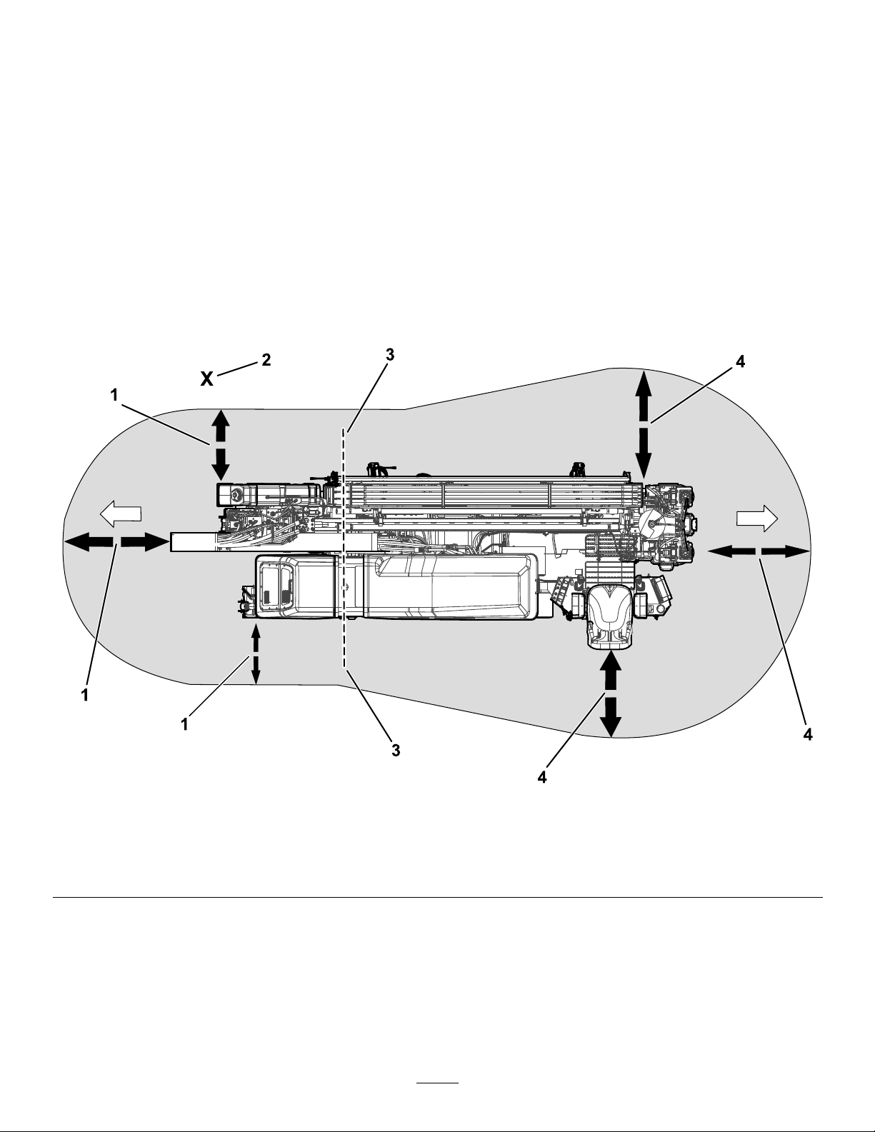
Usethefollowingillustrationtoensurethatbystanders
donotenterthedangerzonewhileyouaretramming
themachine.
Figure3
DrivingDangerZone
1.1.8m(6ft)safetydistance3.Turning-radiuscenter(endofthetrack)
2.Operator4.2.4m(8ft)safetydistance
5
g217464
Page 6
DrillingSafety
•Alwayslowerthepipeloadingguardbeforedrilling
(Figure4).
•Alwaysengagetheexitsidelockoutbefore
operating.
•Keepbystandersandpetsasafedistanceaway
fromthemachine.
•Stopoperatingthemachineifanyoneentersthe
drillingdangerzone.
•Ensurethatnooneapproachesapipewhileitis
spinning.
DrillingDangerZone
Thedangerzoneistheareawithinandaroundthe
machinewhereapersonisexposedtotheriskof
injury.
Thedangerzonedenestheamountofspaceneeded
forsafedrillingoperation,includingmovementofthe
carriage.
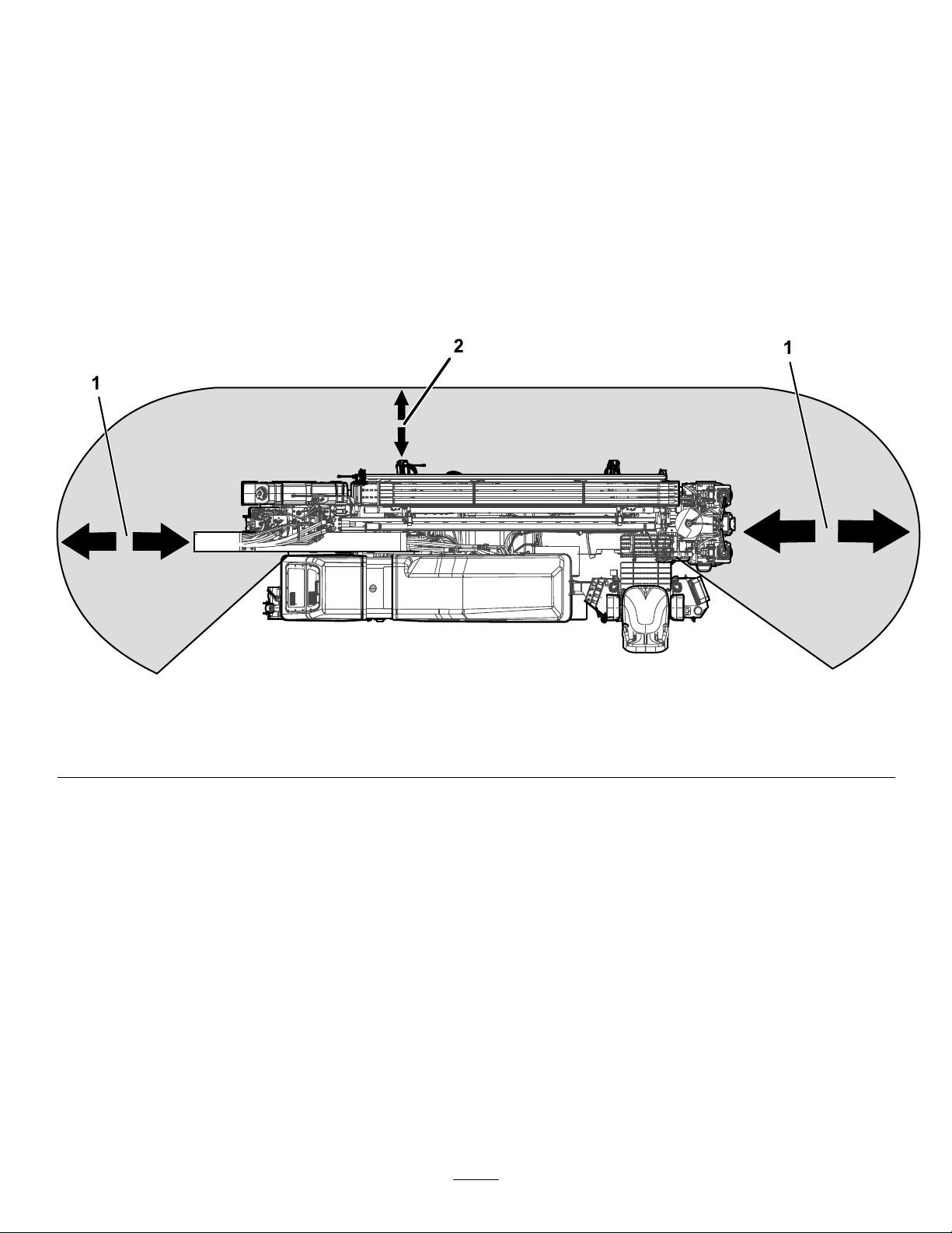
Usethefollowingillustrationtoensurethatbystanders
donotenterthedangerzonewhileyouaredrilling.
Figure4
DrillingDangerZone
1.3m(10ft)safetydistance2.1.8m(6ft)safetydistance
DrillingNearUtilityLines
Important:Beforeoperatinginanareawithhigh-voltagelinesorcables,contacta“One-CallSystem
Directory”service.IntheUSA,call811oryourlocalutilitycompany .Ifyoudonotknowyourlocal
utilitycompany’sphonenumber,callthenationalnumber(USAandCanadaonly)at1-888-258-0808.In
Australia,call1100forthenationwidemarkingservice.Also,contactanyutilitycompaniesthatarenot
participantsofthe“One-CallSystemDirectory”service.
g217462
6
Page 7

UtilityLineColor
Refertothefollowingtablefortheproperutilityline
andthecorrespondingutilitylinecolor(USAand
Canada).
UtilityLine
ElectricRed
Telecommunication,alarmorsignal,
cables,orconduit
Naturalgas,oil,steam,petroleum,or
othergaseousorammablematerial
SeweranddrainGreen
DrinkingwaterBlue
Reclaimedwater,irrigation,and
slurrylines
TemporarysurveymarkingsPink
ProposedexcavationlimitsWhite
UtilityLineColor
Orange
Yellow
Purple
ElectricalandCommunication
LineSafety
•Thealarmwillsoundifthedrillcontactsan
electricalpowersource.
•Donotattempttoleavethemachine.
Note:Youwillbesafeaslongasyoudonotleave
theseatofthemachine.
•Touchinganypartofthemachinemaygroundyou.
•Donotallowanotherindividualtotouchor
approachthemachinewhencharged.
•Thealarmmaysoundifacommunicationline
isbroken,butuntilyouarecertain,youmust
considerthealarmtobeanelectricstrike.
GasLineSafety
WARNING
Ifyoudamageagasline,animmediate
explosionandrehazardcouldoccur.
Leakinggasisbothammableandexplosive
andmaycauseseriousinjuryordeath.
•Donotsmokewhileoperatingthemachine.
WARNING
Ifyouleavetheseatofthemachineortouch
anypartofthemachinewhenitischarged
withelectricity,seriousinjuryordeathcould
result.
Donotleavetheseatofthemachineifthe
machineischargedwithelectricity.
CAUTION
Ifyoudamagetheber-opticcableandlook
intotheexposedhighly-intenselight,youmay
harmyoureyes.
•Shutoffthemachineandremovethekey.
•Removeallindividualsfromtheworkarea.
•Immediatelycontacttheproperemergency
andutilityauthoritiestosecurethearea.
Intheeventofanelectricstrikethatchargesthe
machine,theZap-Alertalarmsystemwillsoundforas
longasthemachineischargedwithpower.
•Shutoffthemachineandremovethekey.
•Removeallindividualsfromtheworkarea.
•Immediatelycontacttheproperemergency
andutilityauthoritiestosecurethearea.
WaterLineSafety
Ifyoudamageawaterline,apotentialood
hazardcouldoccur.
•Shutoffthemachineandremovethekey.
•Removeallindividualsfromtheworkarea.
•Immediatelycontacttheproperemergencyand
utilityauthoritiestosecurethearea.
Note:Immediatelycontacttheproperemergency
andutilityauthoritiestosecuretheareaincasethe
machineischargedandyoucannotleavetheseat
ofthemachine.
Note:Itispossibletostrikeautilitylinewithoutthe
machinebecomingcharged.
7
Page 8
SafetyandInstructionalDecals
Safetydecalsandinstructionsareeasilyvisibletotheoperatorandarelocatednearanyarea
ofpotentialdanger.Replaceanydecalthatisdamagedormissing.
BatterySymbols
Someorallofthesesymbolsareonyourbattery
1.Explosionhazard
2.Nore,opename,or
smoking.
3.Causticliquid/chemical
burnhazard
4.Weareyeprotection9.Flusheyesimmediately
5.ReadtheOperator's
Manual.
6.Keepbystandersasafe
7.Weareyeprotection;
8.Batteryacidcancause
10.Containslead;donot
decalbatterysymbols
distancefromthebattery.
explosivegasescan
causeblindnessandother
injuries
blindnessorsevereburns.
withwaterandgetmedical
helpfast.
discard.
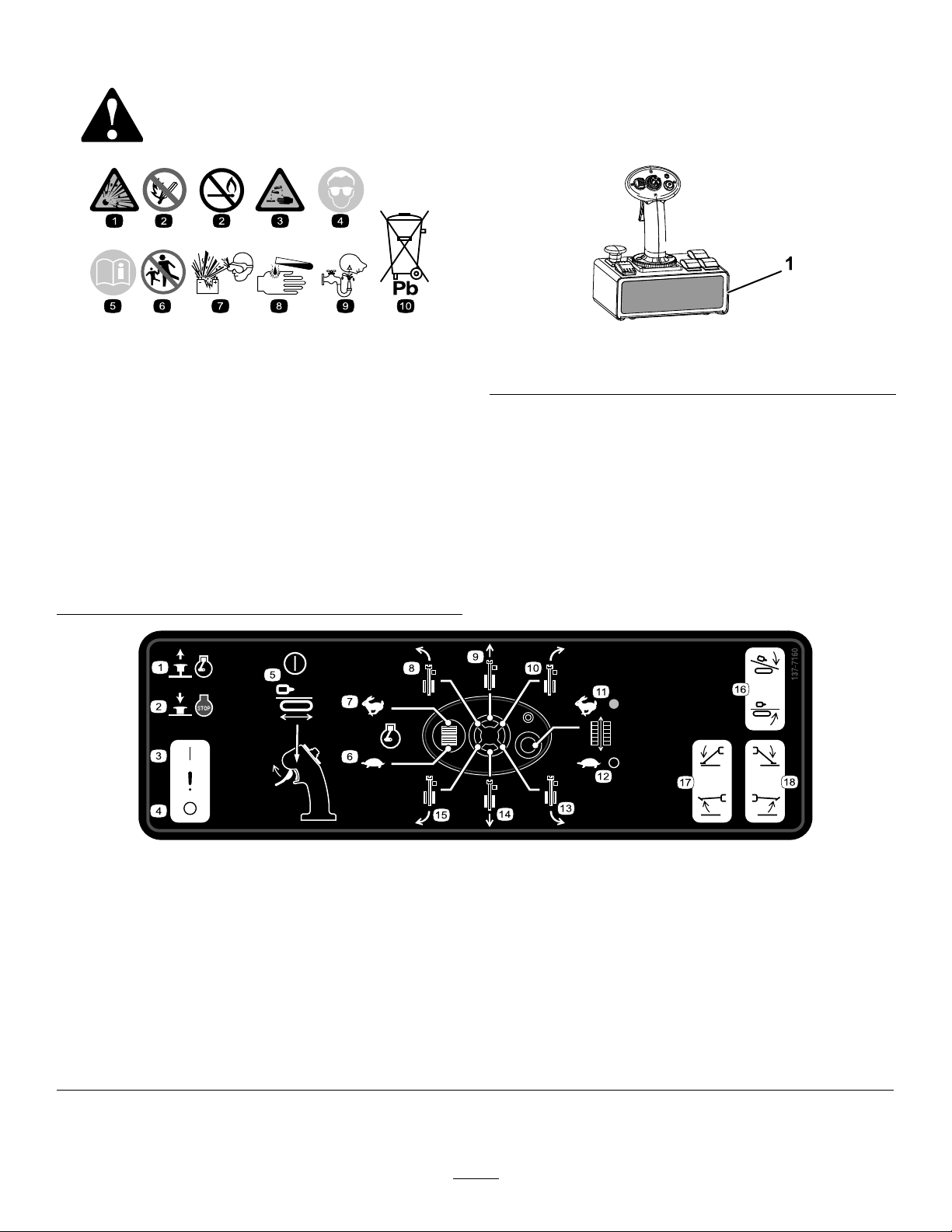
g228534
Figure5
1.137-7160
137-7160
1.Emergencyenginestop—release
2.Emergencyenginestop—engage
3.Setupoperatorpresence—on
4.Setupoperatorpresence—off
5.Trammingoperatorpresence—on/off
6.Enginespeed—decrease
7.Enginespeed—increase
8.Trammingdirection—forward-left17.Leftstabilizerfoot—raise/lower
9.Trammingdirection—forward18.Rightstabilizerfoot—raise/lower
10.Trammingdirection—forward-right
11.Trammingspeed—fast
12.Trammingspeed—slow
13.Trammingdirection—backward-right
14.Trammingdirection—backward
15.Trammingdirection—backward-left
16.Thrustframe—raise/lower
8
decal137-7160
Page 9
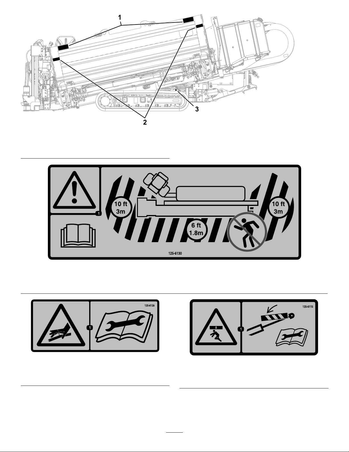
g228521
Figure6
1.125-61303.125-6115
2.125-6128
125-6130
1.Warning—readtheOperator’sManual;stayatleast3m(10ft)awayfromthefrontandrearofthemachineand1.8m(6ft)
awayfromthesidesofthemachine.
decal125-6130
125-6128
1.Highpressureuidhazard,injectionintothebody—read
theOperator’sManualbeforeperformingmaintenance.
decal125-6128
decal125-6115
125-6115
1.Crushinghazard—deploycylinderlocksbeforeperforming
maintenance.
9
Page 10
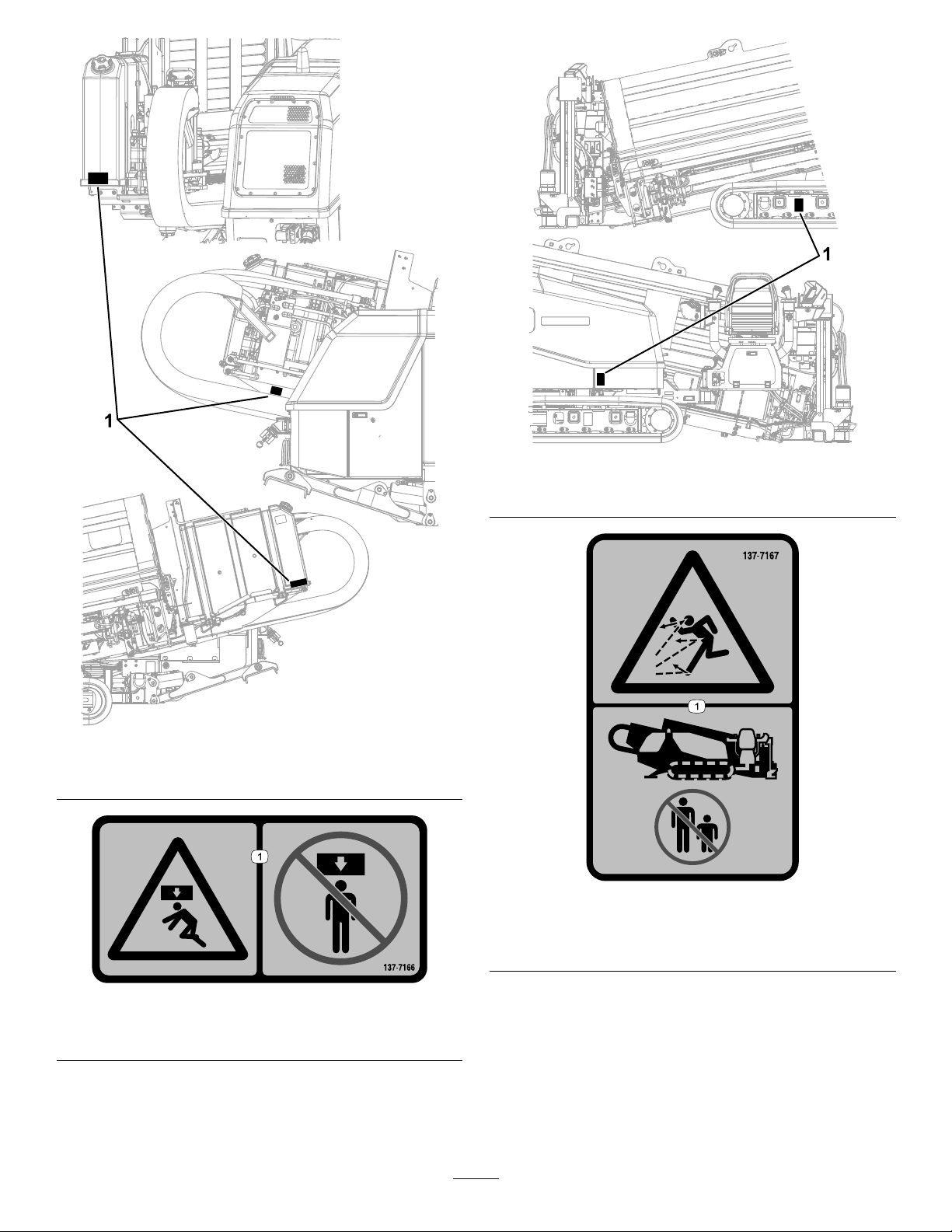
g228523
Figure8
1.137-7167
g228522
Figure7
1.137-7166
decal137-7167
137-7167
137-7166
1.Crushinghazard—donotstandunderthemachine.
1.Thrownobjecthazard—keepbystandersawayfromthe
machine.
decal137-7166
10
Page 11
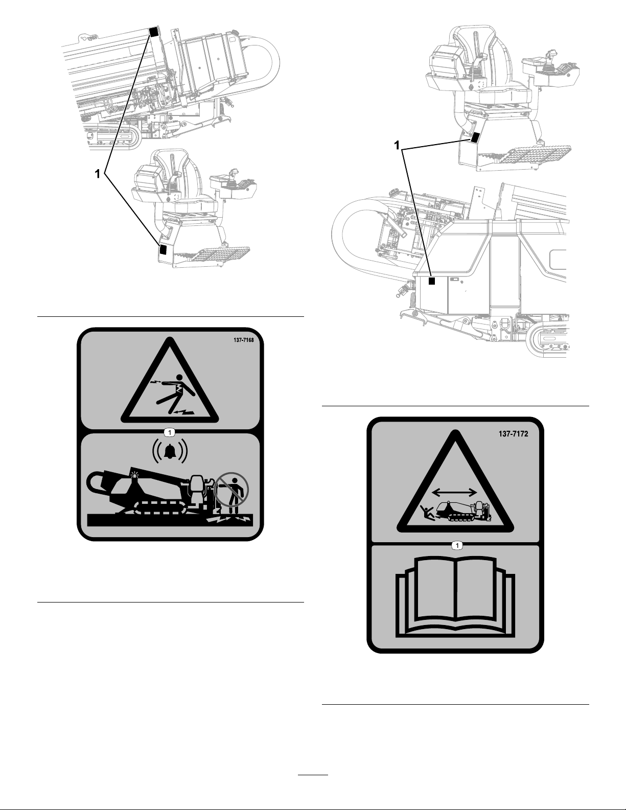
g228524
Figure9
1.137-7168
g228525
Figure10
1.137-7172
decal137-7168
137-7168
1.Electrocutionhazard—donottouchthemachinewhenthe
alarmissounding.
decal137-7172
137-7172
1.Runover/backoverhazard—readtheOperator’sManual.
11
Page 12
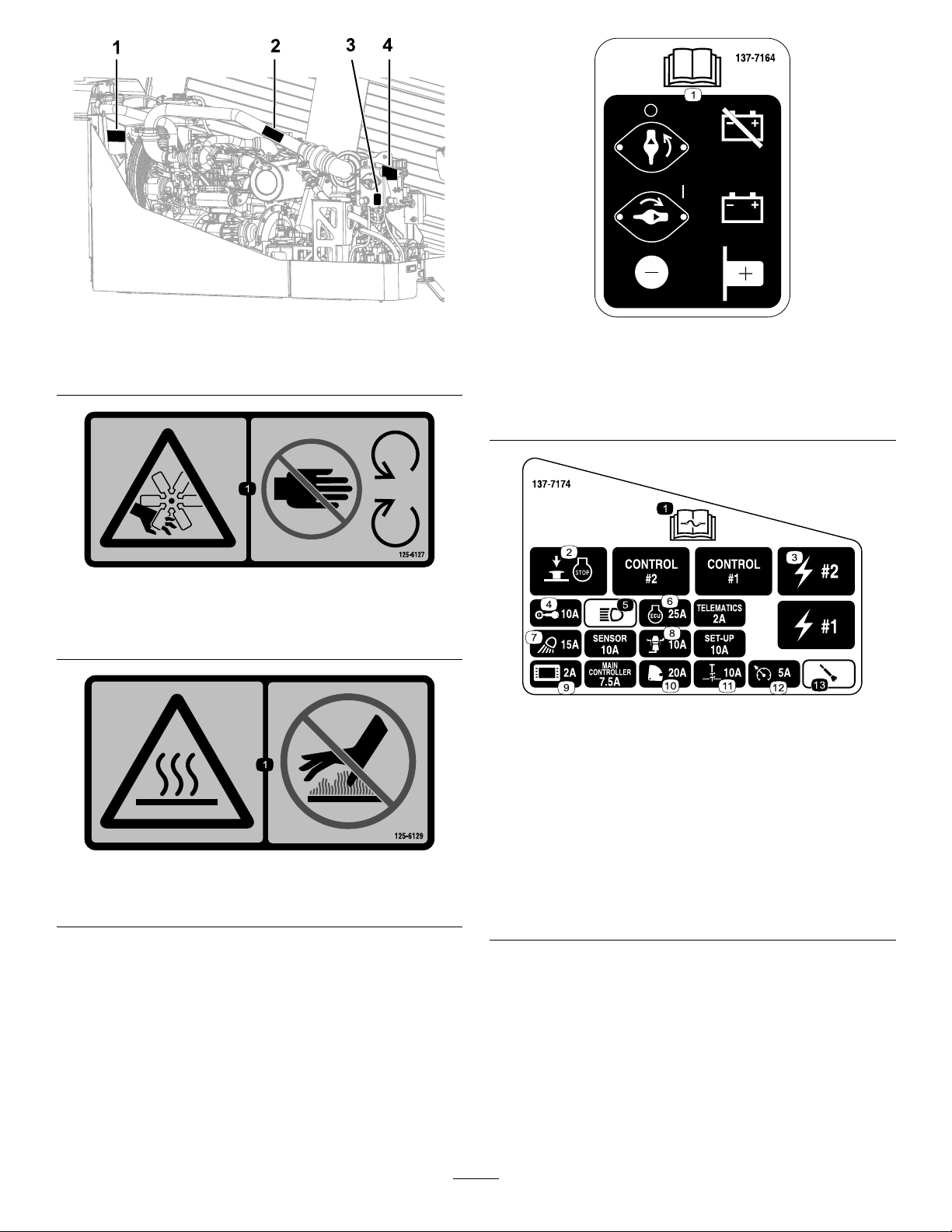
Figure11
1.125-61273.137-7164
2.125-61294.137-7174
125-6127
1.Cutting/dismembermenthazard,fan—keepawayfrom
movingparts.
g228526
decal137-7164
137-7164
1.ReadtheOperator’sManual—rotatecounterclockwise
todisconnectthebattery;rotateclockwisetoconnectthe
battery;thenegativepostislocatedbelowtheswitch;the
positivepostislocatedtothesideoftheswitch.
decal125-6127
decal137-7174
137-7174
125-6129
1.Hotsurface—keepawayfromhotsurfaces.
1.ReadtheOperator’s
8.Operatorplatform
Manualforinformationon
fuses.
2.Emergencyenginestop
9.Display
button
3.Electric
decal125-6129
4.Keyswitch
10.Cam
11.Stake
5.Headlights12.Autodrill
6.Enginecontrolunit13.Airhammer
7.Worklights
12
Page 13
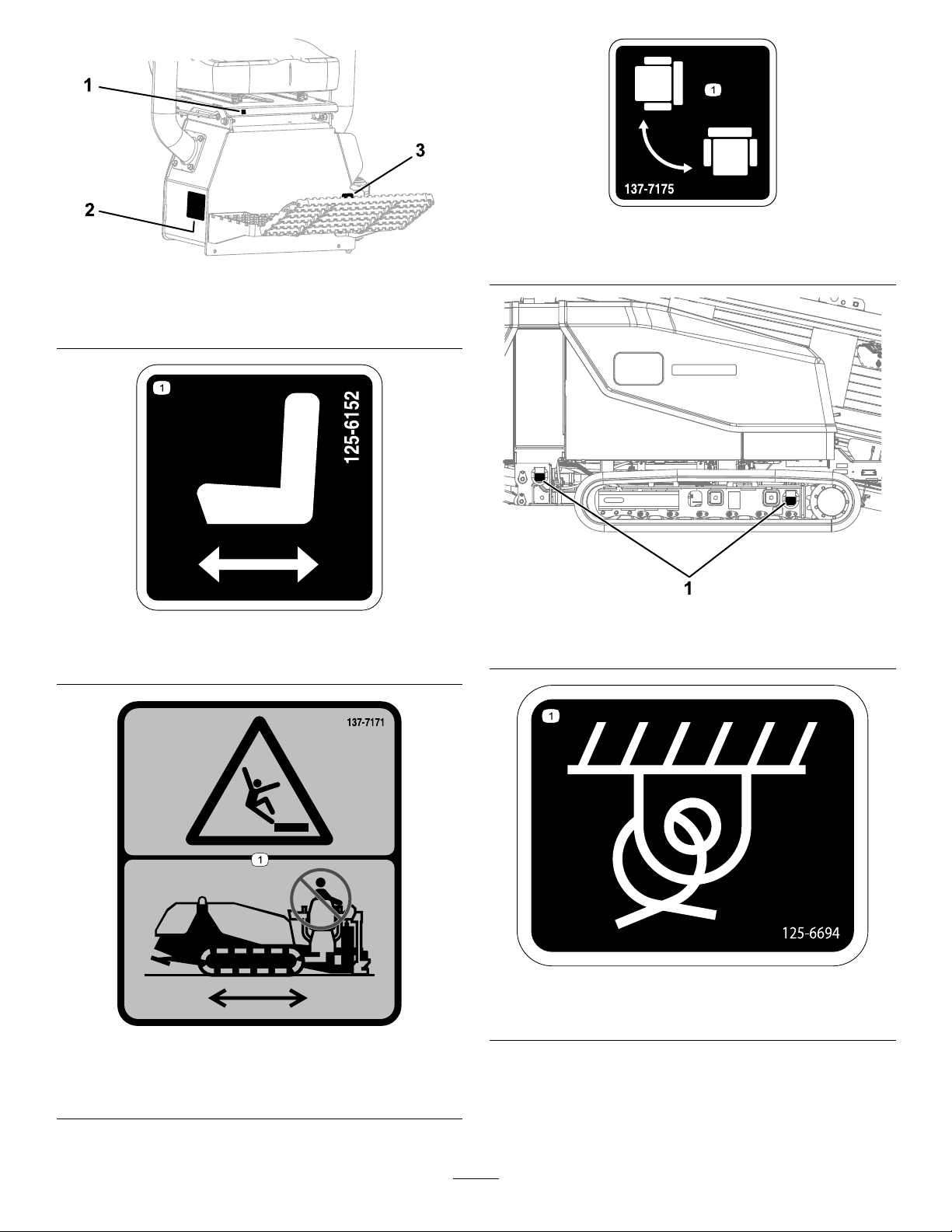
decal137-7175
137-7175
1.125-61523.137-7175
2.137-7171
1.Moveseatforwardandbackward.
Figure12
125-6152
g231766
decal125-6152
1.Rotatetheoperatorplatform.
g228528
Figure13
1.125-6694
137-7171
1.Fallinghazard—donotrideonthemachinewhileitis
moving.
decal125-6694
125-6694
1.Tie-downlocation
decal137-7171
13
Page 14
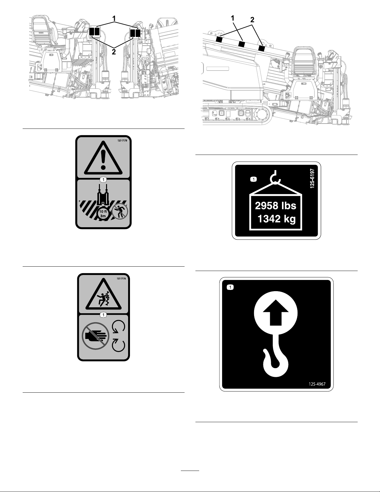
Figure14
1.137-71792.137-7178
137-7179
1.Warning—hazardousarea;keepatleast3m(10ft)away
fromthemachineduringoperation.
g228532
g228533
Figure15
1.125-61972.125-4967
decal137-7179
decal125-6197
125-6197
1.Maxweightlimit—1342kb(2,958lb)
137-7178
1.Entanglementhazard—keepawayfrommovingparts.
decal137-7178
decal125-4967
125-4967
1.Liftpoint
14
Page 15
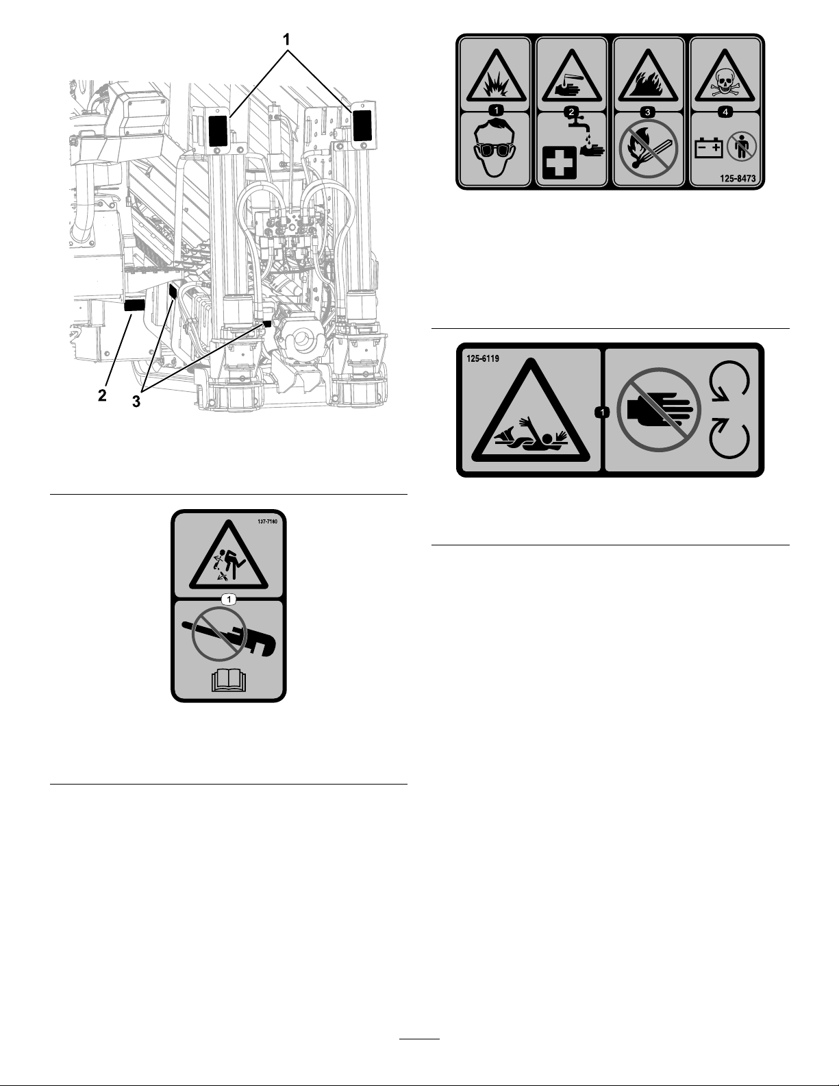
decal125-8473
125-8473
Figure16
1.137-71803.125-6119
2.125-8473
1.Explosionhazard—wear
eyeprotection.
2.Causticliquid/chemical
burnhazard—rinse
3.Firehazard—keepopen
amesaway.
4.Poisonhazard—donot
tamperwiththebattery.
affectedareaandseek
medicalassistance.
g228531
decal125-6119
125-6119
1.Entanglementhazard—keepawayfrommovingobjects.
137-7180
1.Impacthazard—donotuseapipewrench;refertothe
Operator’sManual.
decal137-7180
15
Page 16
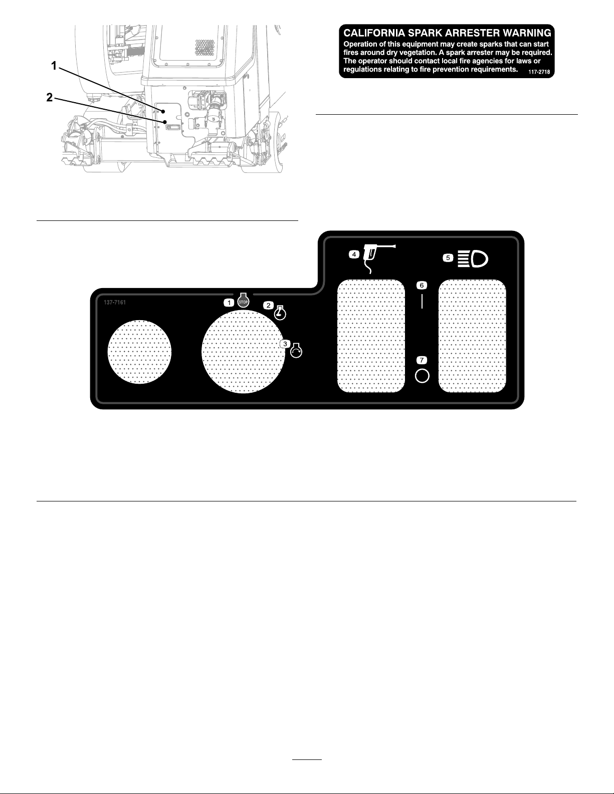
1.117-27182.137-7161
decal117-2718
117-2718
g228960
Figure17
1.Engine—stop5.Headlights
2.Engine—run
3.Engine—start
4.Spraygun
decal137-7161
137-7161
6.On
7.Off
16
Page 17
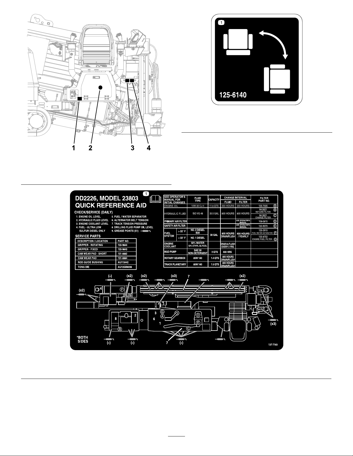
1.125-61403.137-7182
2.137-71834.125-6124
decal125-6140
125-6140
1.Rotatethechair.
g228527
Figure18
1.ReadtheOperator’sManual.
decal137-7183
137-7183
17
Page 18
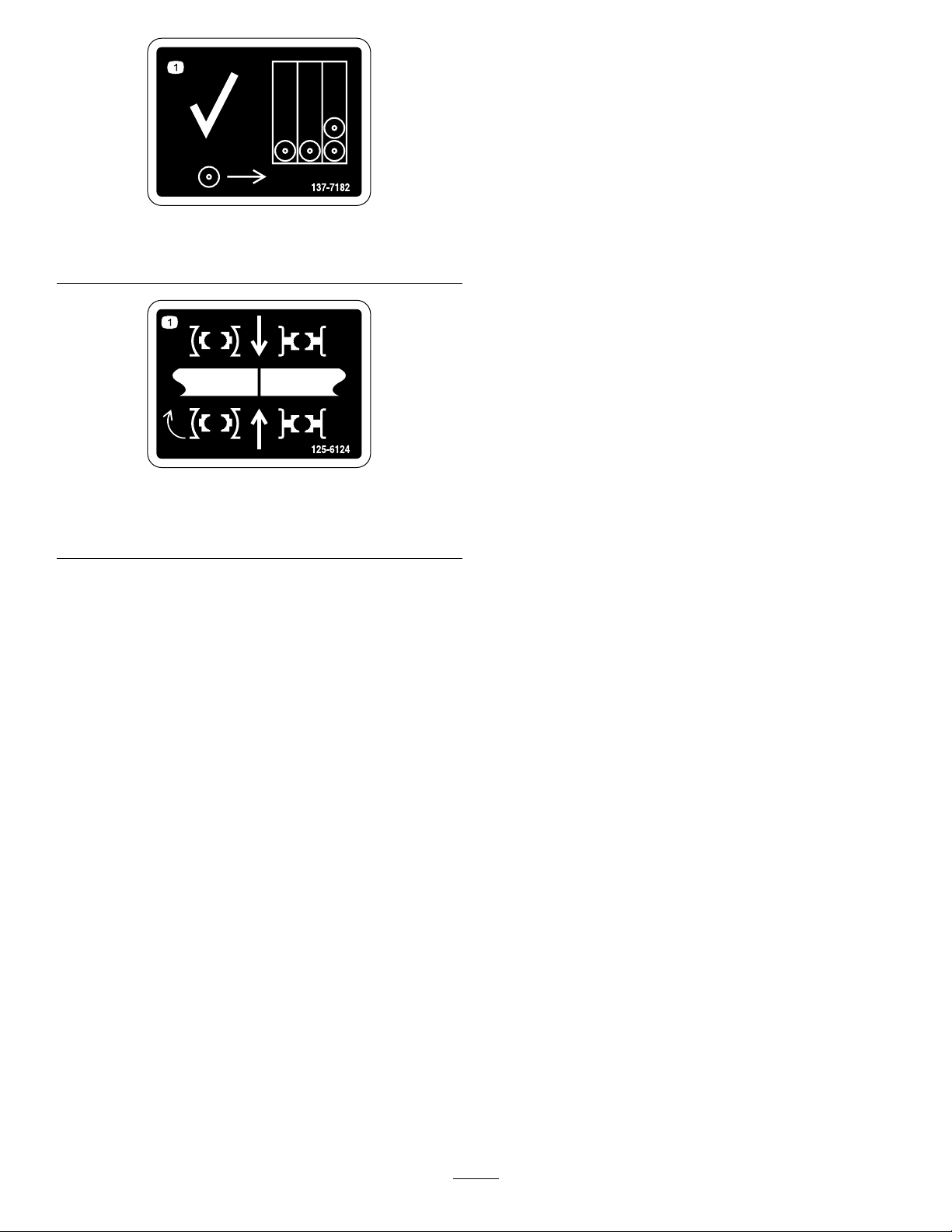
137-7182
1.Loadpipesfrombackrowrst.
125-6124
1.Centerthepipejointbetweentheupperandlower
wrenches.
decal137-7182
decal125-6124
18
Page 19
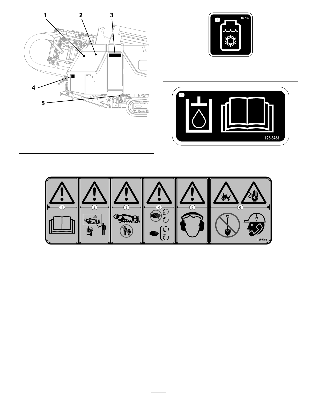
1.137-71654.137-7170
2.125-84835.127-1829
3.137-7169
decal137-7165
137-7165
1.Antifreeze
g228530
Figure19
decal125-8483
125–8483
1.Hydraulicuid;readtheOperator’sManual.
137-7169
1.Warning—readtheOperator’sManual.4.Warning—keepawayfrommovingparts;keepallguardsand
2.Warning—alloperatorsmustbetrainedbeforeoperatingthe
machine.
3.Warning—keepbystandersawayfromthemachine.
coversinplace.
5.Warning—hearingprotectionmustbeworn.
6.Explosionandelectricalshockhazard—donotdig;callyour
localutilitycompany.
decal137-7169
19
Page 20
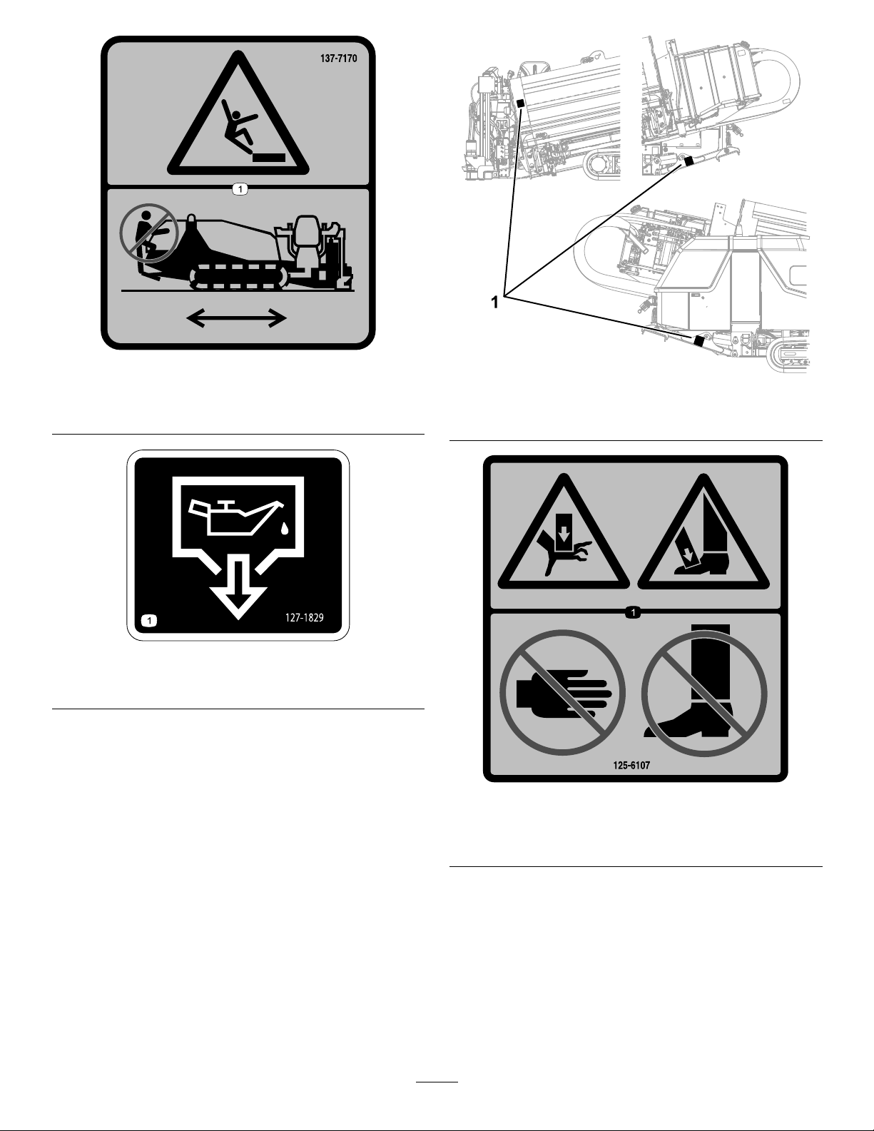
137-7170
1.Fallinghazard—donotclimbonthemachinewhileitis
moving.
127-1829
1.Oildrain
decal137-7170
g228520
Figure20
1.125-6107
decal127-1829
125-6107
1.Crushinghazardofhandandfoot—keephandsandfeet
away.
20
decal125-6107
Page 21
1.137-71773.125-6193
2.137-71764.125-6194
g231767
Figure21
137-7177
1.Mud—On/Off8.Carriagethrustspeed—high
2.Upperwrench—open/close9.Mudow—high
3.Lowerwrench—open/close10.Thrustthecarriageforward(drillmodeIandII);lowerthe
stake(setupmode)
4.Mudow—increase11.Rotatethedrillspindleclockwise(drillmodeI);rotatethe
stakecounterclockwise(setupmode)
5.Mudow—decrease12.Rotatethestakeclockwise(setupmode);rotatethedrill
spindlecounterclockwise(drillmodeI)
6.Rotatethewrenchclockwiseandcounterclockwise(make
andbreakrotation)
13.Raisethestake(setupmode);pullthecarriageback(drill
modeIandII)
7.Autodrill—set14.Rightstakecontrols
21
decal137-7177
Page 22

decal137-7176
137-7176
1.Engine—start10.Rotatethecamassembly.
2.Enginespeed—increase11.Movetothenext
3.Enginespeed—decrease
4.Pipegripperarm—retract
5.Pipegripperarm—extend14.Rotatestakecounter
6.Applytread-joint
compound.
7.Elevator—raise
8.Elevator—lower
9.Pipegripper—open/close
orpreviousstepin
SmartTouch™mode.
12.Camoverridefunctionto
rotatethecamassembly.
13.Lowerthestake(setup
mode);rotatedrillspindle
counterclockwise(drill
modeII)
clockwise(setupmode)
15.Rotatethestakeclockwise
(setupmode)
16.Raisethestake(setup
mode);rotatedrillspindle
clockwise(drillmodeII)
17.Leftstakecontrols
22
Page 23
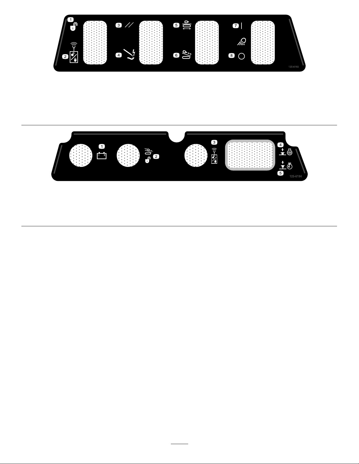
125-6193
1.Exit-sidelockout—reset5.Trammingandsetup
2.Exit-sidelockoutswitch6.Drilling
3.Ground-strike—reset
7.Worklights—on
4.Ground-strikeswitch8.Worklights—off
125-6194
1.Exit-side-lockoutreceiverbattery-statuslight4.Emergencyenginestop—engage
2.Exit-sidelockoutdrill-enabledlight5.Emergencyenginestop—release
3.Exit-sidelockoutstandbylight
decal125-6193
decal125-6194
23
Page 24
ProductOverview
g218957
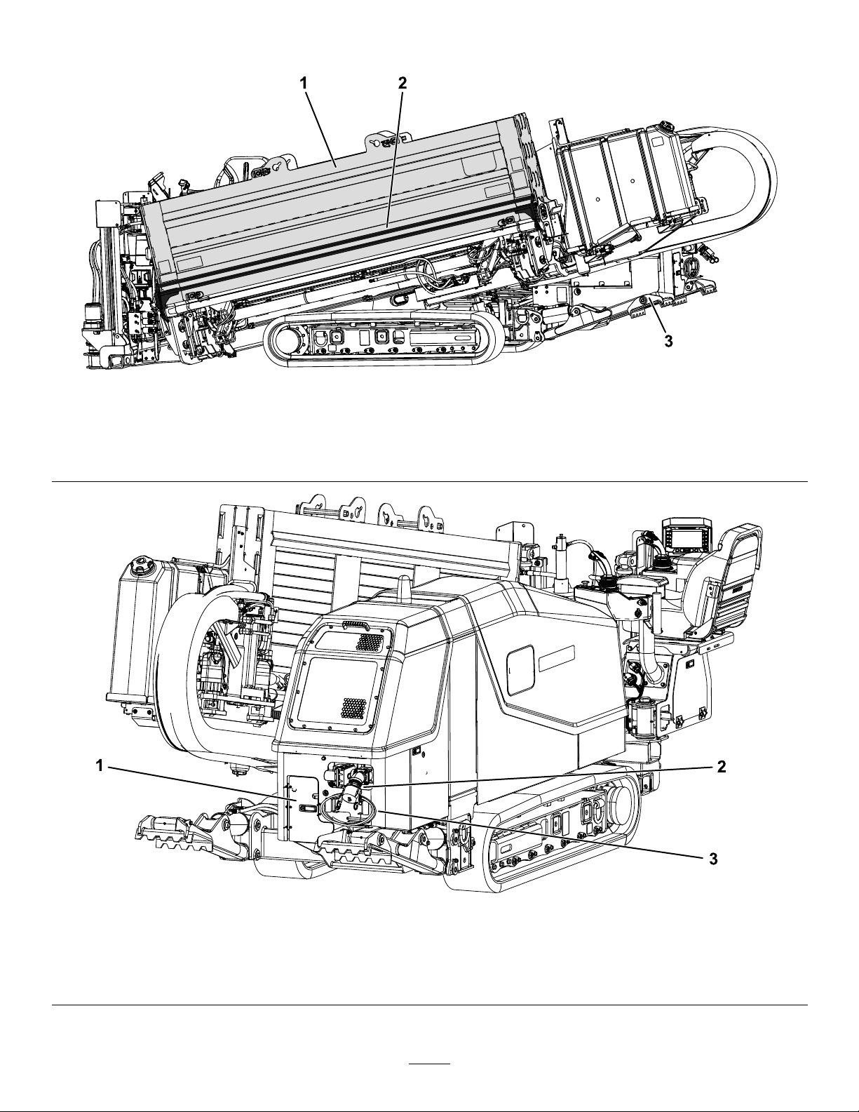
Figure22
LeftSideView
1.Pipebox
2.Safetybar
3.Stabilizerfoot
Figure23
RearView
1.Rearcontrolpanel3.Zap-alertstake
2.Drilling-uid-sourceconnection
24
g218958
Page 25
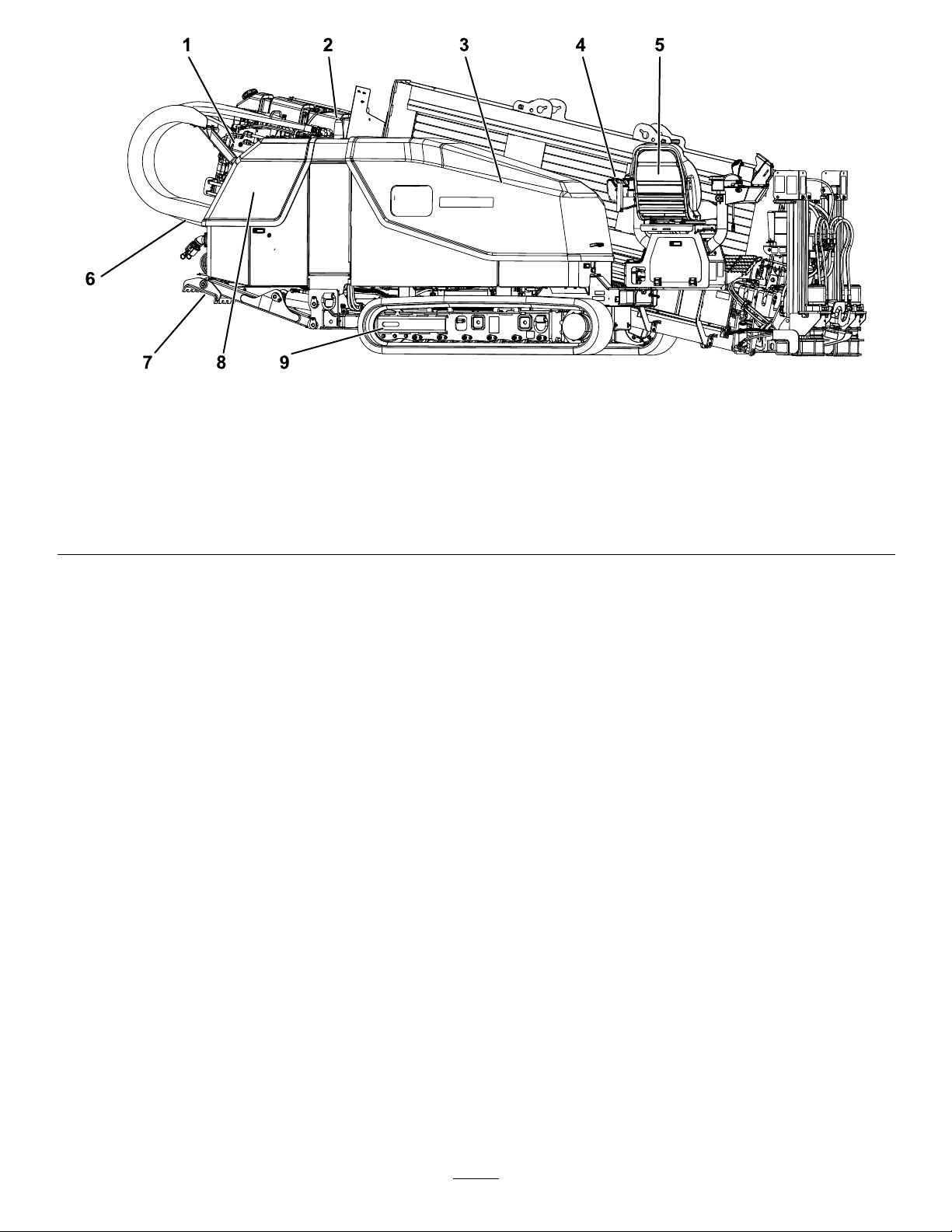
Figure24
RightSideView
1.Carriage6.Thrustframe
2.Zap-alertstrobe
3.Fronthood8.Rearhood
4.Frontcontrolpanel9.Tracks
5.Operatorseat
7.Stabilizerfoot
g218959
25
Page 26
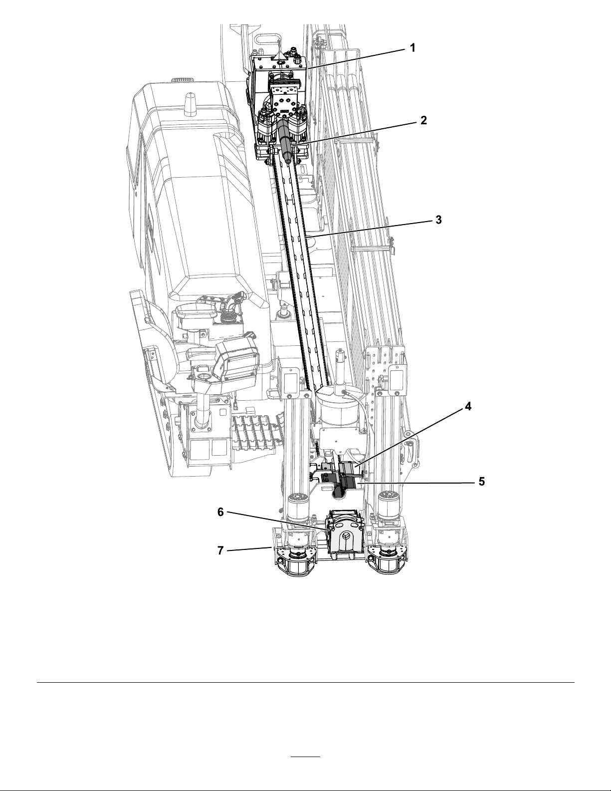
Figure25
Topview
g218960
1.Carriage
5.Lowerwrench
2.Drillspindle6.Pipewiper
3.Thrustframe7.Stake-downtube
4.Upperwrench
26
Page 27
Controls
Refertothefollowingsectionsfortheappropriate
machinecontrols:
•OperatorPlatform(page27)
•TheSoftwareGuide
•FrontControlPanel(page29)
•JoysticksinSetupMode(page30)
•LeftJoystick(page31)
•RightJoystick(page32)
•ExitSideLockout(page33)
•RearControlPanel(page33)
•TravelPendant(page33)
•Battery-DisconnectSwitch(page34)
OperatorPlatform
Theoperatorplatform,locatedontheright,front
cornerofthemachine,containsmostofthecontrols
youusetooperatethedrillingfunctionsofthe
machine.
Operator-PlatformLatch
Theoperatorplatformswingsoutawayfromthe
machine,makingroomforyoutosit.Ithas5positions:
travel(swungallthewayintothemachine),full-out,
and3intermediatepositions.Returntheplatformto
theTRA VELpositionbeforemovingthemachine.
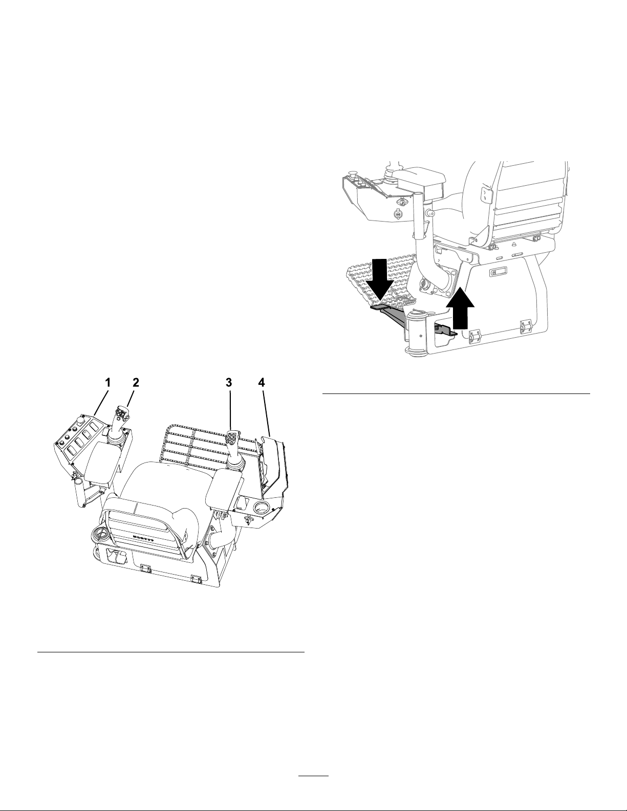
Tomovetheplatform,pushupontherearplatform
latchorpushdownonthefrontplatformlatch(Figure
27).
g218956
Figure27
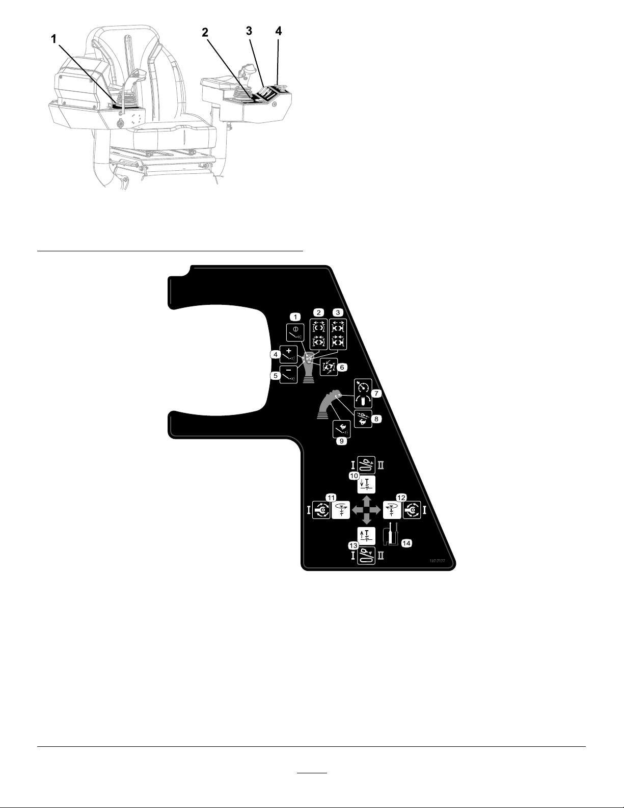
Figure26
1.Frontcontrolpanel3.Rightjoystick
2.Leftjoystick4.Operatordisplay
Operator-ControlsCovers
Thecoversprotecttheoperatorcontrolsfromadverse
weatherconditions,suchasrain,wind,sunlight,etc.
Removethembeforeusingthemachineandreplace
thembeforeleavingthemachinefortheday.
Toreleasetheplatformandswingitoutorin,pushup
onthefrontplatformlatch(Figure27).
g218950
27
Page 28
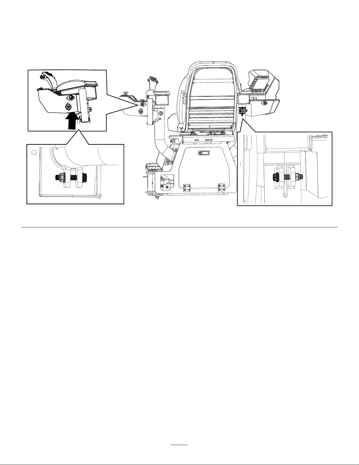
AdjustingtheOperatorConsoleBolts
Tightentheconsoleboltstoaddfrictiontotheconsoles;refertoFigure28.
Theleftconsolecanrotate10degreesin.
Therightconsolecanrotate10degreesinand45degreesout.
Figure28
g230008
28
Page 29
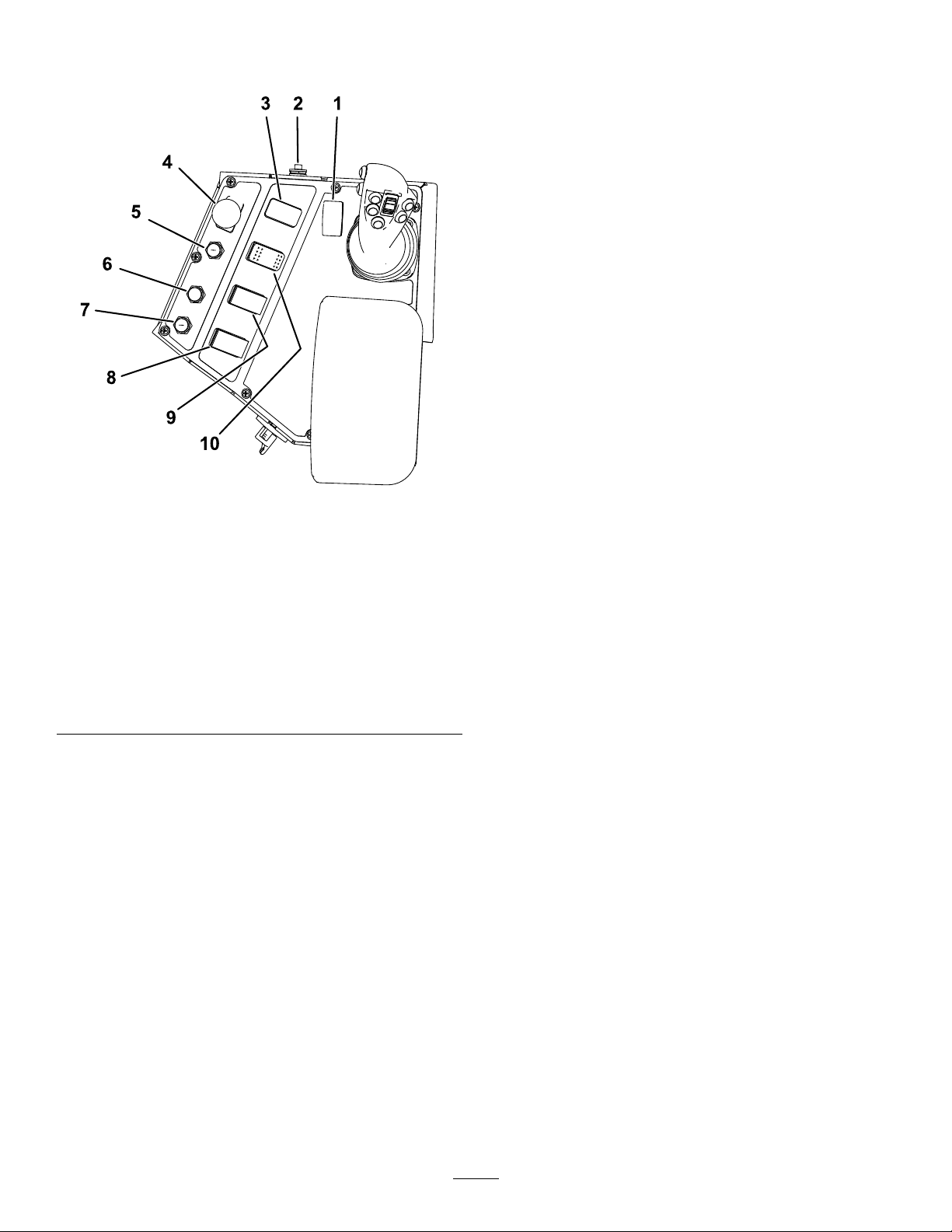
FrontControlPanel
Figure29
1.Engine-speedswitch6.Exit-side
2.Engine-startbutton7.Exit-side-lockouthandheld
3.Work-lightsswitch8.Exit-side-lockout—reset
4.Emergencyenginestop
button
5.Exit-sidelockout—standby
light(orange)
lockout—drill-enabled
light(green)
battery-statuslight(red)
switch
9.Ground-strike-resetswitch
10.Drill/setupswitch
EmergencyEngineStopButton
Pushthisbutton(Figure29)toimmediatelyshutoff
theengineandalldrillingoperations.Youmustpull
thisbuttonoutbeforeyoucanstarttheengineagain.
Exit-SideLockout—StandbyLight
Thislight(Figure29)illuminatesorangewhenthe
exit-sidelockoutisturnedoff,indicatingthatyoumay
resetthesystem.
Exit-SideLockout—Drill-enabledLight
Thislight(Figure29)illuminatesgreenwhenthe
exit-side-lockoutsystemhasbeenresetandthe
machineisreadytodrill.
Exit-Side-LockoutBattery—StatusLight
Thislight(Figure29)illuminatesredwhenthebattery
ontheexit-side-lockouttransmitteristoolowto
transmit.Stopdrillingoperationsandreplacethe
batteriesinthetransmitterbeforecontinuing.
g218968
Exit-SideLockout—ResetSwitch
Pushthisswitch(Figure29)toenabledrilling
operationwhentheyellowresetlightilluminates.
Ground-Strike-ResetSwitch
Pushthisswitch(Figure29)toresettheZap-Alert
systemafteragroundstrikehasoccurredandbeen
xed;refertoDeployingtheZap-AlertSystem(page
51).
Drill/SetupSwitch
Engine-SpeedSwitch
•Pushandholdthetopofthisswitchtoincrease
theenginespeed.
•Pushandholdthebottomofthisswitchto
decreasetheenginespeed.
•Releasetheswitchtomaintainthecurrentengine
speed.
Engine-StartButton
Pushthisbutton(Figure29)tostarttheengine.The
keyswitchontherear,controlpanelmustbeintheON
position.Ensurethatbothemergencystopswitches
areintheraisedposition.
Work-lightsSwitch
Pushthetopofthisswitch(Figure29)toturnthe
machinelightsonorthebottomoftheswitchtoturn
themoff.
Pushthetopofthisswitch(Figure29)toenablethe
setupcontrolsorthebottomoftheswitchtoenable
drillandpipe-loaderfunctions.
29
Page 30
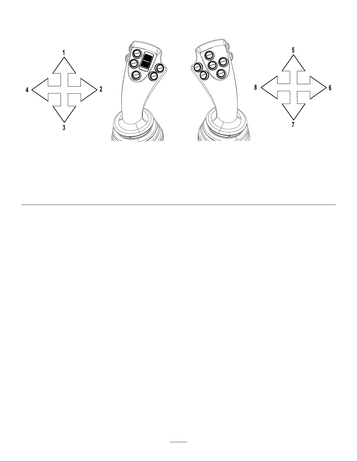
JoysticksinSetupMode
Themachinemustbeinsetupmode(Figure29)andyoumustbeintheseattousethesefunctions.
Figure30
Joysticks–SetupMode
g225942
1.Lowertheleftstakedown
2.Rotatetheleftstakeclockwise
3.Raisetheleftstakeup
4.Rotatetheleftstakecounterclockwise
LeftJoystickinSetupMode
•Forward:Pushthejoystickforwardtolowerthe
leftstakedown.
•Rearward:Pullthejoystickrearwardtoraisethe
leftstakedown.
•Left:Movethejoysticktothelefttorotatetheleft
stakecounterclockwise.
•Right:Movethejoysticktotherighttorotatethe
leftstakeclockwise.
5.Lowertherightstakedown
6.Rotatetherightstakeclockwise
7.Raisetherightstakeup
8.Rotatetherightstakecounterclockwise
RightJoystickinSetupMode
•Forward:Pushthejoystickforwardtolowerthe
rightstakedown.
•Rearward:Pullthejoystickrearwardtoraisethe
rightstakedown.
•Left:Movethejoysticktothelefttorotatetheright
stakecounterclockwise.
•Right:Movethejoysticktotherighttorotatethe
rightstakeclockwise.
30
Page 31

LeftJoystick
g226145
Figure31
LeftJoystickinDRILLmode
1.Raisetheelevator
2.Lowertheelevator7.Retractthepipegripperarm
3.Open/Closethepipegripper
4.Rotatethecamassembly9.Applytread-jointcompound
5.GotothepreviousstepinSmartT ouch™mode
6.GotothenextstepinSmartTouch™mode
8.Extendthepipegripperarm
Figure32
LeftJoystick—DirectionalControls
g226143
1.Rotatethedrillspindlecounterclockwise(DrillModeII)3.Rotatethedrillspindleclockwise(DrillModeII)
2.Noaction4.Noaction
Pushthejoystickleftandholdthecamrockerswitchatthesametimetousethecamoverridefunction.
Important:Thisoverridestheanti-crashpreventionwarningandcouldcausedamagetothemachine.
Pushthecamrockerswitchforwardtorotatethecamassemblyout.
Pushthecamrockerswitchbackwardtorotatethecamassemblyin.
31
Page 32

RightJoystick
Thejoystickcontrolsvarydependingonthecontrolmodeyouselectwhenpoweringupthemachine.Thereare
2controlmodes:DrillModeIandDrillModeII;refertotheControl-SelectScreenintheSoftwareGuidefor
informationonsettingthecontrolmodes.
Figure33
RightJoystick
1.Turnthemudonoroff4.OpenandClosetherearwrench7.Settheautodrillonoroff
2.Increasethemudowmomentarily5.Openandclosethefrontwrench8.Setthecarriagetohighspeed
3.Deceasethemudowmomentarily
6.Rotatethewrenchclockwiseand
counterclockwise(makeandbreak
rotation)
9.Maxowofmud
g226146
RightJoystick—DrillModeI
Figure34
RightJoystick—DrillModeI
1.Thrustthecarriageforward
2.Rotatethedrillspindle
counterclockwise
3.Pullthecarriageback
4.Rotatethedrillspindle
clockwise
RightJoystick—DrillModeII
g226144
g226144
Figure35
RightJoystick—DrillModeII
1.Thrustthecarriageforward
2.Noaction4.Noaction
3.Pullthecarriageback
32
Page 33

ExitSideLockout
Theexit-side-lockoutsystemprovidestheindividuals
workingaroundthemachinewithameanstodisable
thedrillpipefromrotatingandthrusting.
Formoreinformationandinstructions,refertothe
Operator’sManualfortheExit-side-lockoutsystem.
•Engine-offposition—turnthekeytothispositionto
shutofftheengine.Theenginecannotbestarted
fromtheoperatorplatformwhenthekeyisinthis
position.
•Engine-runposition—turnthekeytothisposition
afterstartingtheengine.Turningthekeytothis
positionalsoenablestheenginestartbuttonfrom
theoperatorplatform.
RearControlPanel
Figure36
1.Travelpendantbracket3.Engine,keyswitch
2.Fluid-pumpswitch
4.OK-to-Startlight
•Engine-startposition—turnthekeytothisposition
tostarttheengine.ReleasethekeytotheRUN
positiononcetheenginehasstarted.
Fluid-PumpSwitch
Usethisswitchtoturnontheuidpumptousethe
spraygunwhencleaningthemachine.
TravelPendant
RefertoFigure36forlocation.
g229102
OK-to-StartLight
Thegreenlightilluminateswhenthemachineisready
tostart.
Ifthelightdoesnotilluminate,checkthe2emergency
stopbuttons.Theyneedtobedisengagedbeforethe
machinecanstart.
Engine,KeySwitch
Thekeyswitchhas3positionsasfollows(Figure36):
Figure37
1.Engine-offposition
2.Engine-runposition
3.Engine-startposition
g225940
Figure38
1.Operatorpresenceswitch
(tramming)
2.Enginespeedswitch
3.Tramming-Direction
Joystick
4.Errorindicatorlight(when
blinking)
g220853
5.Trammingspeedswitch10.Emergencyenginestop
6.Thrustframeswitch
7.Rightstabilizerfootswitch
8.Leftstabilizerfootswitch
9.Operatorpresenceswitch
(setup)
button
Usethecorrespondingoperatorpresenceswitchto
operatethesetupandtrammingfunctions.
33
Page 34

Ifyoureleasetheoperatorpresenceswitchwhile
operating,youwillneedtoreleaseallofthecontrols
beforeresumingoperation.
OperatorPresenceSwitch
Pushandholdthisbuttontoenabletheothercontrols
onthetravelpendant.Themachinestopsmoving
whenyoureleasethisbutton.
EngineSpeedSwitch
Battery-DisconnectSwitch
Openthefronthoodtoaccessthe
BATTERY-DISCONNECTswitch;refertoOpening
theFrontandRearHoods(page67).
TheBA TTERY-DISCONNECTswitchislocatedtotheright
oftheengine;itisusedtoelectricallydisconnectthe
batteryfromthemachine.
Important:Donotusethebattery-disconnect
switchtoturnofftheengine.
•Pushthetopofthisswitchtoincreasetheengine
speedin100rpmincrements.Holdtheswitchto
rapidlyincreasetohighidle.
•Pushthebottomofthisswitchtodecreasethe
enginespeedin100rpmincrements.Holdthe
switchtorapidlydecreasetolowidle.
•Releasetheswitchtomaintainthecurrentengine
speed.
TrammingDirectionJoystick
Usethejoysticktocontrolthedirectionofthemachine.
Themachinewilltravelinthedirectionyoumovethe
joystick.
ErrorIndicatorLight
Thislightlightsupwhenthe2-speedbuttonispushed.
Thelightwillblinkthereisaninternalerrorwiththe
travelpendant.
Drive-SpeedSwitch
Theswitchsetsthespeedatwhichthemachine
travels.Pushtheswitchtoalternatebetweenhigh
andlowspeed.
TurntheBA TTERY-DISCONNECTswitchtotheONorOFF
positiontoperformthefollowing:
•T oenergizethemachineelectrically,rotatethe
BATTERY-DISCONNECTswitchclockwisetotheON
position(Figure39).
•T ode-energizethemachineelectrically,rotatethe
BATTERY-DISCONNECTswitchcounterclockwiseto
theOFFposition(Figure39).
g218942
Figure39
Specications
Note:Specicationsanddesignaresubjectto
changewithoutnotice.
ThrustFrameSwitch
Usethisswitchtoraiseandlowerthethrustframe.
RightStabilizerFootSwitch
Usethisswitchtoraiseandlowertherightstabilizer
foot.
LeftStabilizerFootSwitch
Usethisswitchtoraiseandlowertheleftstabilizer
foot.
EmergencyEngineStopButton
Pushthisbuttontoimmediatelyshutofftheengine
andallmovement/drillingoperations.Youmustpull
thisbuttonoutbeforeyoucanstarttheengineagain.
Machine
Width
Length
Height
Weight
34
147cm(58inches)
521cm(205inches)
198cm(78inches)
4,302kg(9,485lb)
Page 35

Operation
UnderstandingHorizontal
Determinetheleftandrightsidesofthemachinefrom
thenormaloperatingposition.
BeforeOperation
BeforeOperationSafety
GeneralSafety
•Theownermustensurethatalloperatorsare
welltrainedandcompetenttosafelyoperatethe
machine.
•Neverallowchildrenoruntrainedpeopleto
operateorservicethemachine.Localregulations
mayrestricttheageoftheoperator.
•Becomefamiliarwiththesafeoperationofthe
equipment,operatorcontrols,andsafetysigns.
•Knowhowtostopthemachineandshutoffthe
enginequickly.
•Checkthatoperator-presencecontrols,safety
switches,andshieldsareattachedandfunctioning
properly.Donotoperatethemachineunlessthey
arefunctioningproperly.
DirectionalDrilling
Horizontaldirectionaldrillingisaprocessusedfor
drillingahorizontalborethroughthesoilandunder
obstructionssuchasroads,buildings,bodiesofwater,
etc.Onceyoudrillthebore,pullbacktheutilitylinesor
pipesthroughtheboreandconnectthemasneeded.
Becauseitdoesnotrequireverymuchdisturbanceof
thesurface,installationofutilitiesusingdirectional
drillingpreservestheenvironmentandsavesboth
timeandmoneyovertraditionalinstallationmethods
suchastrenching.
Wheninstallingcablingorpipeusingadirectionaldrill,
completethefollowingsteps:
1.Gathersiteinformation.
Beforeoperatinginanareawithhigh-voltage
linesorcables,contacta“One-CallSystem
Directory”service.IntheUSA,call811oryour
localutilitycompany.Ifyoudonotknowyour
localutilitycompany’sphonenumber,callthe
nationalnumber(USAandCanadaonly)at
1-888-258-0808.InAustralia,call1100forthe
nationwidemarkingservice.Also,contactany
utilitycompaniesthatarenotparticipantsofthe
“One-CallSystemDirectory”service.Please
refertoDrillingNearUtilityLines(page6)for
moreinformation.
•Inspecttheareawhereyouwillusethemachine
andremoveallobjectsthatthemachinecould
throw.
•Keepthemanual(s)withthemachine.Goto
www.T oro.comforareplacementmanual.
FuelSafety
•Useextremecareinhandlingfuel.Itisammable
anditsvaporsareexplosive.
•Extinguishallcigarettes,cigars,pipes,andother
sourcesofignition.
•Useonlyanapprovedfuelcontainer.
•Donotremovethefuelcaporllthefueltank
whiletheengineisrunningorhot.
•Donotaddordrainfuelinanenclosedspace.
•Donotstorethemachineorfuelcontainerwhere
thereisanopename,spark,orpilotlight,such
asonawaterheaterorotherappliance.
•Ifyouspillfuel,donotattempttostarttheengine;
avoidcreatinganysourceofignitionuntilthefuel
vaporshavedissipated.
Beforefullyplanningtheborepath,gather
informationaboutthejobsitesuchasthe
locationofotherutilities,obstaclesatthesite,
andwhatregulationsandpermitsyouneed
tocompletethejob;refertoGatheringSite
Information(page36).
2.Plantheborepath.
Beforedrilling,plantheborepathbasedonthe
informationyougathered.RefertoPlanningthe
BorePath(page39).
3.Preparethejobsiteandthemachine.
Beforedrilling,preparethejobsitewithanentry
point,depth-gaugehole(optional),andanexit
hole.Drivethemachinetothejobsite,setitup
fordrilling,andconnectittoadrilling-uidmixer.
Note:Whendrilling,connectthemachine
toadrilling-uidmixerthatmixeswaterwith
bentoniteclayandotheringredients.The
machinepumpsthismixture,referredtoas
drillinguidor“mud,”throughthedrillpipeand
outofthedrillbit.Thedrillinguidlubricatesthe
drillbit,helpstoholdtheboreopenwhiledrilling,
andmixeswiththespoils,ushingthemoutof
theborethroughtheentrypoint.
35
Page 36

RefertoPreparingtheJobSiteandthe
Machine(page44)forinstructionsonpreparing
thejobsiteandthemachine.
4.Drillthebore.
Drilltheborein3stages:
A.Entry
Intheentryphaseofthebore,pushthedrill
bitandheadintothegroundatanangle
ofupto16degrees.Afterpushinginone
ormorepipes,begindrillingdownand
forwarduntilyoureachthedesireddepthor
depth-gaugehole(ifused).
B.HorizontalReach
Afterreachingthedesireddepth,pushthe
bitforward,steeringthebittoahorizontal
depth.Thesondeemitsaradiosignal
fromthesondehousing,allowingthe
locating-equipmentoperatoronthesurface
totrackthelocationanddepthofthehead
usingthesondereceiverasyoudrilland
steeritalongaplannedpath..
C.Exit
Onceyouhaveattainedtheplanned
horizontalreach,steertheheadupatan
angle,similartoyourentryangle,bringing
thebitintotheexitholeortrench.
RefertoDrillingtheBore(page57).
5.Backreamtheboreandpullbackthecabling
orpipe.
Afterenteringtheexithole,acrewmember
detachesthedrillbitandsondehousingfromthe
drillpipe.Attachareamingbitandtheendof
thecableorpipetobepulledthroughthebore.
Thereamingbitisdesignedtoenlargethebore
asyoupullitback.Pumpdrillinguidthrough
thepipetothereamingbitasyoupullthecable
orpipebackthroughtheboretolubricatethe
reamerandallowthecableorpipetoslideeasily
throughthebore.Continuepullingthepipeback
untilthereamerreachesthedepth-gaugehole
orexitsattheentrypoint.Removethereamer
andproductfromthedrillpipe,pullingthepipe
therestofthewaybacktothemachine.
RefertoBackreamingandPullback(page60)
forinstructionsonbackreamingandpulling
cableorpipe.
6.Finishtheboreandleavethejobsite.
Aftercompletingtheoperation,disconnectand
cleanthemachine,andloaditonthetrailer;
refertoFinishingtheJob(page63).
GatheringSiteInformation
PlanningtheInitialPath
Beforedrilling,planthepathyouwillboreandprepare
asfollows:
•Createabasicplanforthebore,mappingoutthe
proposedpath.
–Noteanyobstacleswhichmayaffectthebore
suchaslargetrees,bodiesofwater,buildings,
etc.
–Planthepathoftheboretoavoidasmany
obstaclesaspossible.
–Determinethedepthofanybodiesofwaterto
becrossedtoensurethatyoucangetdeep
enoughtogounderthem.
•Determinethedepthyouneedtoinstallthe
materialatandtheminimumbendradiusofboth
thedrillpipeandthematerialbeinginstalled.This
willaffecthowlongtheboreneedstobeand
atwhatangleyoucanenterandexit;referto
PlanningtheBorePath(page39).
•Havetheareaoftheborepathmarkedforutility
lines(intheUScall811).Ensurethatalllinesare
markedonyourblueprints/boreplanaswell.
•Contactthelocalauthoritiestoarrangeforany
permitsandtrafccontrolthatyouwillneedto
conductthejob.
InspectingtheProposedJobSite
Physicallyinspectthesiteasfollows:
•Notetheterrain,slopes,valleys,hills,andany
featuresnotplannedforpreviously.
Determinethedegreeofslopeatboththe
proposedentrypointandexitpoint.
•Determinewhatthesoiltypesareintheareaand,
ifpossible,andwhattheyareatthedepthyou
willbeboring.Youmayneedtodigtestholesat
intervalsalongtheborepathtofullydeterminethis.
•Walktheareaoftheborepathlookingfor
anypossibleunmarkedobstructions.Lookfor
manholes,pedestals,oldfoundations,etc.
•Identifyallhazardsofwhichyouwillbepassing
within3m(10ft).
Commonhazardsincludethefollowing:
–Gaslines
–Electricalpowerlines
36
Page 37

–Crystallinesilicaandotherdust
Ifyouwillbedrillingthroughorcuttingconcrete,
sand,orothersubstancesthatcreatedusts
orfumes,youneedtoensurethatyouandall
workerswearbreathingprotectiontoprotect
yourlungsfromthedust.
DANGER
Contactingundergroundhazardswith
themachinewhiledrillingorreaming
cancauseexplosion,electrocution,
breathingproblems,severetrauma,and
deathtoyouorbystanders.
◊Ensurethatallpersonnelatthe
jobsitewearpersonalprotective
equipmentincludingahardhat,eye
protection,electricallyinsulated
safetybootsandgloves,andhearing
protection.
◊Keepbystandersandspectators
awayfromthejobsite,includingthe
completeborepath.
◊Locateandexposeallelectricand
gaslinesthatyouwillbecrossingby
carefulhanddigging.
◊EnsurethatyouusetheZap-Alert
systemwheneveroperatingthe
machine.
DANGER
Drillingintoanelectricpowerline
willcausethemachinetobecome
electriedandmayelectrocuteyouor
anybystanders.
◊Keepbystandersandspectators
awayfromthejobsite,includingthe
completeborepath.
◊Locateandexposeallelectriclines
thatyouwillbecrossingbycareful
handdigging.
◊Havetheelectriccompanyturnoff
thepowertoanylinesyouwillbe
crossingbeforedrilling.
◊Usethereceivertotracktheexact
positionofthedrillheadwhen
approachingelectriclines.
◊Beforedrilling,setupandusethe
Zap-Alertsystemwhichisdesigned
tonotifyinthecaseofanelectric
strike.IftheZap-Alertalarmtriggers,
stopwhatyouaredoinganddo
notleavetheoperator’sposition.
RefertoDeployingtheZap-Alert
System(page51)fordetailed
instructionsonusingtheZap-Alert
system.
DANGER
Drillingintoagaslinecancausean
explosionorre,burning,injuring,or
killingyouorothersinthevicinityof
thebreak.
◊Donotsmokeorhaveanysourceof
ameneargaslinesorateitherend
ofaborethatwillbecrossingagas
line.
◊Keepbystandersandspectators
awayfromthejobsite,includingthe
completeborepath.
◊Locateandexposeallgaslinesthat
youwillbecrossingbycarefulhand
digging.
◊Havethegascompanyturnoffthe
gastoanylinesyouwillbecrossing
beforedrilling.
◊Usethereceivertotracktheexact
positionofthedrillheadwhen
approachinggaslines.
37
Page 38

WARNING
Machiningorhandlingstone,masonry,
concrete,metal,andothermaterials
cangeneratedust,mists,andfumes
containingchemicals,suchassilica,
knowntocauseseriousorfatalinjury
orillness,suchasrespiratorydisease,
silicosis,cancer,birthdefects,orother
reproductiveharm.
◊Controldust,mist,andfumesatthe
sourcewherepossible.Watershould
beusedfordustsuppressionwhen
feasible.
◊Usegoodworkpracticesand
followtherecommendationsofthe
manufacturerorsuppliers,OSHA,
andotheroccupationalandtrade
associations.
◊Whenthehazardsfrominhalation
cannotbeeliminated,theoperator
andanybystandersshouldweara
respiratorapprovedbyOSHAforthe
materialbeinghandled.
WARNING
SilicosisWarning:Grinding,cutting,
ordrillingstone,masonry,concrete,
metal,andothermaterialswithsilica
intheircompositionmaygiveoff
dustormistcontainingcrystalline
silica.Silicaisabasiccomponent
ofsand,quartz,brick,clay,granite,
andnumerousothermineralsand
rocks.Repeatedand/orsubstantial
inhalationofairbornecrystallinesilica
cancausefatalrespiratorydiseases,
includingsilicosis.Inaddition,some
otherauthoritieshavelistedrespirable
crystallinesilicaasasubstance
knowntocausecancer.Whencutting
suchmaterials,followrespiratory
precautions.
38
Page 39

PlanningtheBorePath
Beforesettingupthejobsite,youneedtoplantheborepath,includingthefollowing:
Figure40
g218955
1.Boreentry
2.Beginningofbore-at-depthpoint5.Endofbore-at-depthpointandboreexit
3.Boredepth
•Boreentry
Thisisthelocationwhereyousetupthemachine
andthedrillbitenterstheground.Depending
onconditions,thiswilltypicallybesetback
9to15m(30to50ft)fromthebeginningof
the-bore-at-depthpoint.
•Beginningofbore-at-depthpoint
Thisisthepointwhereyouwanttheutilityline
orpipetoendafterinstallationiscomplete.Itis
typicallythepointatwhichtheborelevelsout
andbeginstoborehorizontally.Thismaybethe
sameastheentrypoint,oryoumaydigaseparate
depth-gaugeholeatthispoint(Figure40).
•Boredepth
Thisthedepthatwhichyouwanttoinstallthe
utilitylineorpipe.
•Obstaclesinthepath
Youwillneedtosteeraroundorunderobstacles.
Itisimportanttoknowwheretheseobstacleswill
bebeforestartingsothatyoucanplanwhereto
beginsteeringpriortoreachingtheobstacle.
•Endofbore-at-depthpoint
Thisisthepointwhereyouwanttheutilitylineor
pipetobeginafterinstallationiscomplete.Often
thiswillalsobetheboreexit.
•Boreexit
Thisisthelocationwherethedrillheadwillexit
thegroundandthepointatwhichyouwillpullthe
utilitylinesorpipeintothebore.Ifthispointwill
beatthesurfaceinsteadofatinstallationdepth,
4.Obstacle
youwillneedtodeterminethedistancefromthe
end-of-bore-at-depthlocationneededforsteering
thedrilltothesurface,typically9to15m(30to50
ft)fromtheend-of-the-bore-at-depthpoint.
DeterminingtheBoreEntryPoint
Oneofthemorechallengingaspectsofplanningthe
borepathistodeterminetheentrypointofthebore.
Youneedtotakethefollowingtraitsintoaccountwhen
determiningthelocationoftheentrypoint:
•Boredepth
Thisthedepthatwhichyouwanttoinstalltheutility
lineorpipe.Thismachineisdesignedprimarilyfor
installationsbetween1and3m(3.5to10ft).
•Pipeandmaterialexibility
The3m(10ft)pipesusedonthismachinecan
extoan8%pitchoverthelengthofthepipe;
thisequatestoabendofnomorethan20cm(8
inches)offofastraightpath(Figure41).
Important:Ifyousteerthepipetobend
sharperthan20cm(8inches)perpipe,you
maydamagethepipesandtheirconnections.
Youmustalsomakesteeringchanges
graduallyovertheentirelengthofeachpipe.
Ifyousteerthewhole20cm(8inches)in
only25to50cm(1to2ft)oftravel,youcan
permanentlydamagethepipes.
39
Page 40

Figure41
1.20cm(8inches)
Thisexibilityisoftenratedinmaterialsasa
minimumbendradius,whichistheradiusofthe
circleformedifthematerialorpipes,connected
together,werebenttoformagiantcircle.The
minimumradiusofacirclemadewiththepipe
usedwiththismachineis31m(101ft).
•Entrypitch
Theentrypitchistheangleatwhichthedrillbit
enterstheground.Withthetracksonlevelground,
thestabilizersdown,andthestake-downplate
ontheground,thedrillframeangleisabout15
degreesora27%pitch.Thispitchwillchange
dependingontheslopeofthegroundandother
factorsofthejobsite.Y oucanalsoreducethis
pitchabitbybuildingupthegroundunderthe
stake-downplatebeforepositioningthemachine.
Youcandeterminetheactualpitchofthedrill
framebyplacingthedrillbitandsondehousing
ontheframeandthenusethereceivertodisplay
thepitch.
g021765
g218953
Figure43
1.18%pitch3.53cm(21inches)
2.3m(10ft)
Thesteeperyourentrypitchis,thedeeperyour
boremustbeduetothelimitationsofthepipe
exibility.Typically ,youneedtoinsertthedrillbit
andatleast1/3ofapipeintothegroundbefore
youcanstartsteeringtowardthebeginningofthe
borepoint.Figure42,Figure43,andthefollowing
tableillustratetherelationshipbetweenentrypitch
anddepth.
Figure42
g218953
1.26%pitch3.76cm(30inches)
2.3m(10ft)
40
Page 41

Note:Thedepthsgiveninthefollowingtablearefor3m(10ft)ofcombineddrillheadandpipe.As
yousteerup,thepitchofthesteeredsectionchangesandcanbemonitoredwiththereceiver.Usethe
followingtabletoidentifyhowmanylengthsofpipewillbenecessarytoinsertandsteertothebeginning
pointandhelpyouchooseanentrypoint.
Pitch
1%2cm(1inch)26%76cm(30inches)
2%5cm(2inches)27%79cm(31inches)
3%10cm(4inches)28%81cm(32inches)
4%13cm(5inches)29%84cm(33inches)
5%15cm(6inches)30%86cm(34inches)
6%18cm(7inches)31%91cm(36inches)
7%20cm(8inches)32%94cm(37inches)
8%25cm(10inches)33%97cm(38inches)
9%28cm(1 1inches)34%99cm(39inches)
10%30cm(12inches)35%102cm(40inches)
11%33cm(13inches)36%104cm(41inches)
12%36cm(14inches)37%107cm(42inches)
13%39cm(15inches)38%109cm(43inches)
14%43cm(17inches)39%112cm(44inches)
15%46cm(18inches)40%114cm(45inches)
16%48cm(19inches)41%117cm(46inches)
17%51cm(20inches)42%117cm(46inches)
18%53cm(21inches)43%119cm(47inches)
19%56cm(22inches)44%122cm(48inches)
20%61cm(24inches)45%124cm(49inches)
21%64cm(25inches)46%127cm(50inches)
22%66cm(26inches)47%130cm(51inches)
23%69cm(27inches)48%133cm(52inches)
24%71cm(28inches)49%135cm(53inches)
25%74cm(29inches)50%137cm(54inches)
Allmeasurementsareapproximateandwillvarydependingonsoilconditions.
DepthChangeper10feet
Pitch
DepthChangeper10feet
Note:RefertotheguidancesystemOperator’sManualformoreinformation.
Giventheinformationinthetable,youcancalculatethenumberofpipesrequiredtoreachyourbeginning
pointattheappropriatedepth.Tororecommendsthatyoustarttheentrypointadistancebackfromyour
beginning-at-depthpointbythesamedistanceasthelengthofpipesyouwillneedtoreachthatpoint.Thiswill
ensurethatyouhaveenoughextraspacesoyouwillnotover-steeranddamagethepipes.
41
Page 42

Thefollowingexampleillustratestheprocessgivenaninstallationusingthemaximumentrypitchofthe
machine(26%)onlevelground:
Figure44
1.26%pitch4.185cm(73inches)7.14.7m(45ft)
2.76cm(30inches)5.203cm(80inches)
3.142cm(56inches)6.208cm(82inches)
•Y ouinserttherst3m(10ft)ofdrillbit/pipeinto
thegroundwithnosteering.Theendofthedrillbit
is76cm(30inches)deep(Figure44).
g218954
•Y oubeginsteeringupforthenext3m(10ft),
pushingthepipesinatthemaximumpitchchange
of8%.Thisresultsinachangeofpitchfrom26%
atthebeginningofthe3m(10ft)to18%atthe
endofthe3m(10ft)foranaveragepitchof22%.
Giventhat,thedrillheadlowersanother66cm(26
inches)andisnow142cm(56inches)deep.
•Continuingsteeringupforthenext3m(10ft)at
an8%pitchchange,yourpitchchangesfrom18%
to10%foranaveragepitchof14%.Giventhat,
thedrillheadlowersanother43cm(17inches)
andisnow185cm(73inches)deep.
•Continuingsteeringupforthenext3m(10ft)at
an8%pitchchange,yourpitchchangesfrom10%
to2%foranaveragepitchof6%.Giventhat,the
drillheadlowersanother18cm(7inches)andis
now203cm(80inches)deep.
•Levelingthedrillheadfrom2%to0%takesless
than1.5m(5ft)moreforanaldepthof208cm
(82inches).Reachingthisnalpointtook4and
ahalf,3m(10ft)pipes.Soforthisexampleyour
entrypointshouldbe14.7m(45ft)backfromthe
beginning-at-depthpointofyourinstallation.
42
Page 43

Thefollowingexampleillustratestheprocessgivenaninstallationusingthemachineatan18%pitchon
levelground:
Figure45
1.18%pitch3.96cm(38inches)5.119cm(47inches)
2.53cm(21inches)4.114cm(45inches)6.10.6m(35ft)
g218952
•Y ouinserttherst3m(10ft)ofdrillbit/pipeinto
thegroundwithnosteering.Theendofthedrillbit
is53cm(21inches)deep(Figure45).
•Y oubeginsteeringupforthenext3m(10ft),
pushingthepipesinatthemaximumpitchchange
of8%.Thisresultsinachangeofpitchfrom18%
atthebeginningofthe3m(10ft)to10%atthe
endofthe3m(10ft)foranaveragepitchof14%.
Giventhat,thedrillheadlowersanother43cm(17
inches)andisnow96cm(38inches)deep.
•Continuingsteeringupforthenext3m(10ft)at
an8%pitchchange,yourpitchchangesfrom10%
to2%foranaveragepitchof6%.Giventhat,the
drillheadlowersanother18cm(7inches)andis
now114cm(45inches)deep.
•Levelingthedrillheadfrom2%to0%takesless
than1.5m(5ft)moreforanaldepthof119cm
(47inches).Reachingthisnalpointtook3anda
half,3m(10ft)pipes.Soforthisexample,your
entrypointshouldbe10.6m(35ft)backfromthe
beginning-at-depthpointofyourinstallation.
Important:Youcanusetheinformationcontained
inthissectiontodetermineboththespaceneeded
tosteeruptotheexitpointifneededandalsoto
steeraroundobstacles.
MappingtheBorePath
Withtheinformationyougatheredpreviously ,mapout
thepathofthebore,identifyingthefollowingsothat
youcanmarkthesitelater:
•Entrypoint
•Locationofthemachineandsupportingequipment
•Beginningofbore-at-depth
•Anyobstaclesthatyouneedtosteeraroundand
thelocationswhereyouneedtostartsteeringto
getaroundorunderthem
•Anyutilitylinesyouwillneedtocross
•Slopeandsoilchangesalongthepaththatwill
affectthebore
•Endofthebore-at-depth
•Exitlocationifitisdifferentthantheendofthebore
43
Page 44

PreparingtheJobSiteand
Checkingthe
theMachine
Beforedrilling,preparethejobsiteandmachineas
follows:
•MarkingandPreparingtheBorePath(page44)
•T estingtheZap-AlertSystem(page45)
•LoadingtheDrillPipes(page46)
•FillingtheFuelTank(page46)
•CheckingtheEngine-OilLevel(page74)
•CheckingtheCoolantLevelintheRadiator(page
86)
•CheckingtheHydraulicFluid(page91)
•CheckingtheDrilling-Fluid-PumpOilLevel(page
94)
•LoadingandUnloadingtheMachine(page48)
•UnderstandingHorizontalDirectionalDrilling(page
35)
•ConnectingtoaDrilling-FluidSource(page52)
•SettingUptheDrillHeadandTracking
System(page50)
•SettinguptheMachineforDrilling(page51)
•DeployingtheZap-AlertSystem(page51)
Safety-InterlockSwitches
CheckingtheOperatorPresence
Safety-InterlockFunctionsonthe
OperatorPlatform
1.Starttheengine.
2.Withtheenginerunning,risefromtheseatand
pressajoystickfunction.
Note:Thedrillfunctionsshouldnotengage.
Iftheydoengage,thereisamalfunctioninthe
interlocksystemthatyoushouldcorrectbefore
resumingoperation.
CheckingtheOperatorPresence
Safety-InterlockFunctionsonthe
TravelPendant
Youwillneed2peopleforthisprocedure.
1.Starttheengine.
2.Withtheenginerunning,have1personsitin
theseat.
3.Usingthetravelpendant,pressthecontrolsto
tramthemachine.
MarkingandPreparingthe
BorePath
1.Walktheborepath,markingitontheground
withmarkingpaintsothatthereceiveroperator
willbeabletofollowthepath.
2.Handdigtoexposeanyburiedutilitylines,
previouslymarked,thattheborepathwillbe
crossing.Thiswillallowthereceiveroperatorto
knowexactlywheretheyare.
3.Ifyouareexitingtheboreatgroundleveland
notinanexistingtrench,diganangledholeinto
whichthebitwillenterattheendofthebore.
4.Ifdesired,digaholetothebeginning-of-the-bore
pointwhereyoucandisconnectthepipeorlines
afterpullingthemback.
Note:Thetrammingfunctionsshouldnot
engage.Iftheydoengage,thereisamalfunction
intheinterlocksystemthatyoushouldcorrect
beforeresumingoperation.
4.Withtheenginerunning,usethetravelpendant
andpressthecontrolstolowerthestabilizerfeet
whilenotholdingtheoperatorpresencebutton.
Note:Thestabilizerfeetfunctionsshould
notengage.Iftheydoengage,thereisa
malfunctionintheinterlocksystemthatyou
shouldcorrectbeforeresumingoperation.
5.Withtheenginerunning,usethetravelpendant
andpressthecontrolstotramthemachinewhile
notholdingtheoperatorpresencebutton.
Note:Thetrammingfunctionsshouldnot
engage.Iftheydoengage,thereisamalfunction
intheinterlocksystemthatyoushouldcorrect
beforeresumingoperation.
44
Page 45

CheckingthePipeLoadGuard SafetyInterlockFunctions
Youwillneed2peopleforthisprocedure.
audiblealarmintheeventthatthedrillbit,reamer,
orstakebreaksintoanenergizedpowerline.Inthe
eventofanelectricstrike,themachinebecomes
energized,settingoffthealarm.
1.Starttheengine.
2.Lowerthepipeloadguard.
3.Withtheenginerunning,have1personsitinthe
seatandbeginthedrillingprocess.
4.Raisethepipeloadguard.
Note:Thecamassemblyshouldnotengage.
Ifitdoesengage,thereisamalfunctioninthe
interlocksystemthatyoushouldcorrectbefore
resumingoperation.
TestingtheZap-Alert
System
DANGER
IftheZap-Alertsystemactivateswhiledrilling,
themachinewillbecomeenergized.Ifyou
stepoffoftheoperatorplatformorifsomeone
touchesthemachineorwetgroundnearthe
machineorinthebore,youortheycouldbe
electrocuted,causingseriousinjuryordeath.
•TesttheZap-Alertsystembeforedrilling.
•Deploythegroundingstakebeforedrilling.
Ensurethatthestakeisfullyinsertedinto
moistsoil.
TesttheZap-Alertsystembeforeusingthedrilleach
day,asfollows:
1.Removethegroundcablefromitsstorage
positionattherearofthemachine(Figure49).
2.Laythegroundingstakeatonthegroundaway
fromthemachine.Donotdrivethestakeinto
theground.
Important:Donotallowthestaketotouch
anypartofthemachine.
3.Openthefronthood;refertoOpeningtheFront
andRearHoods(page67).
4.ConnectanalligatorclipfromtheZap-Alert
testertothegroundingstudontheZap-Alert
system(Figure46andFigure47).
g218967
Figure46
•IftheZap-Alertistriggered:
–Stayintheseatanddonottouchthe
groundoranyotherpartofthemachine
untilthepowerhasbeenturnedoff.
Donotpourliquidsorurinatefromthe
operatorplatformontotheground.
–Stopdrilling,stopthedrilling-uidow,
andretractthedrilloutoftheground.
–Keepeveryoneawayfromthemachine.
–Keepstandingorrunningwaterand
drillinguidcontainedclosetothe
machine.Keepwateranddrillinguid
sourcesawayfromthebrokenline.
–Contacttheutilitycompanytohave
powershutofftothebrokenline.Do
notresettheZap-Alertsystemuntilthe
powerhasbeenturnedoff.
TheZap-Alertsystemisanelectricstrikesensing
deviceonthemachinethattriggersastrobelightand
g230010
Figure47
5.Connecttheotheralligatorcliptoametal
componentofthemachineframe.
6.PushtheTESTbuttonontheZap-Alerttester
(Figure48).
TheZap-Alertalarmshouldsound,andthe
strobeontopofthefronthoodshouldash.
45
Page 46

MountingaFire
Extinguisher
Mountyourreextinguisherbelowtheoperatorseat
(Figure50).
Note:Areextinguisherisnotprovidedwiththe
machine.
Figure48
7.PushtheZAP-ALERTRESETbuttontostopthe
alarm(Figure29).
8.Disconnectthealligatorclipsfromthegrounding
studandthemachine.
9.Storethegroundingstakeintheholderatthe
rearofthemachine(Figure49).
g230009
Therecommendedreextinguisherisadrychemical
reextinguisherapprovedforclassBandCres.
Operateandmaintainthereextinguisherperthe
instructionsonthereextinguisher.
g218948
Figure50
LoadingtheDrillPipes
Figure49
Ifeithertheaudiblealarmorthestrobelightfailed
totriggerwhenyoupushedtheTESTbutton,have
themrepairedbeforedrillingwiththemachine.
RefertotheSoftwareGuidefortheprocedureon
loadingdrillpipesintothepipeboxorontothedrill
string.
g218966
FillingtheFuelTank
FuelTankCapacity
114L(30USgallons)
FuelSpecication
Important:Useonlyultra-lowsulphurdiesel
fuel.Fuelwithhigherratesofsulfurdegrades
thedieseloxidationcatalyst(DOC),whichcauses
operationalproblemsandshortenstheservicelife
ofenginecomponents.
Failuretoobservethefollowingcautionsmay
damagetheengine.
•Neverusekeroseneorgasolineinsteadofdiesel
fuel.
•Nevermixkeroseneorusedengineoilwiththe
dieselfuel.
46
Page 47

•Neverkeepfuelincontainerswithzincplatingon
theinside.
•Donotusefueladditives.
PetroleumDiesel
Cetanerating:45orhigher
Sulfurcontent:Ultra-lowsulfur(<15ppm)
FuelTable
Dieselfuelspecication
ASTMD975
No.1-DS15
No.2-DS15
EN590EuropeanUnion
ISO8217DMX
JISK2204GradeNo.2
KSM-2610
Location
USA
International
Japan
Korea
•Useonlyclean,freshdieselfuelorbiodieselfuels.
•Purchasefuelinquantitiesthatcanbeusedwithin
180daystoensurefuelfreshness.
Usesummer-gradedieselfuel(No.2-D)at
temperaturesabove-7°C(20°F)andwinter-grade
fuel(No.1-DorNo.1-D/2-Dblend)belowthat
temperature.
Note:Useofwinter-gradefuelatlowertemperatures
provideslowerashpointandcoldowcharacteristics
whicheasesstartingandreducesfuellterplugging.
Usingsummer-gradefuelabove-7°C(20°F)
contributestowardlongerfuelpumplifeandincreased
powercomparedtowinter-gradefuel.
Biodiesel
Thismachinecanalsouseabiodieselblendedfuelof
uptoB20(20%biodiesel,80%petroleumdiesel).
Sulfurcontent:Ultra-lowsulfur(<15ppm)
Biodieselfuelspecication:ASTMD6751or
EN14214
Blendedfuelspecication:ASTMD975,EN590,
orJISK2204
Important:Thepetroleumdieselportionmust
beultra-lowsulfur.
Observethefollowingprecautions:
•Biodieselblendsmaydamagepaintedsurfaces.
•UseB5(biodieselcontentof5%)orlesserblends
incoldweather.
•Monitorseals,hoses,gasketsincontactwithfuel
astheymaybedegradedovertime.
•Fuellterpluggingmaybeexpectedforatime
afterconvertingtobiodieselblends.
•ContactyourAuthorizedServiceDealerformore
informationonbiodiesel.
AddingFuel
1.Movethemachinetoalevelsurface.
2.Positionthethrustframeinthehorizontal
position.
3.Shutofftheengine.
4.Cleanaroundthefuel-tankcapandremovethe
cap.
g218946
Figure51
5.Addfuelandinstallthefuel-tankcap.Wipeup
anyspilledfuel.
PerformingDaily
Maintenance
Beforestartingthemachineeachday,perform
theEachUse/Dailyprocedureslistedinthe
RecommendedMaintenanceSchedule(s)(page65).
StartingandShuttingOff
theEngine
Tostarttheengine,dothefollowing:
1.Openthefronthood;refertoOpeningtheFront
andRearHoods(page67).
2.Turnthebatterydisconnectswitchtothe
ONposition;refertoBattery-Disconnect
Switch(page34).
3.Closeandlatchthehood.
4.Openthedoorontherearcontrolpanel.
5.TurnthekeytotheRUNposition.
Ensurethatok-to-startlightisilluminated.If
thelightisnotilluminated,ensurethatthe
47
Page 48

emergency-engine-stopbuttonsarereleased
(Figure29andFigure38).
6.TurnthekeytotheST ARTpositionuntilthe
enginestarts,thenreleaseit.
Toshutofftheengine,turnthekeytotheOFFposition.
Inanemergency,youcanalsoshutoffthe
engineandallprocessesbypushingthe
EMERGNECY-ENGINE-STOPbuttononeitherthetravel
pendantorthecontrolpanel.
TrammingtheMachine
RefertoTrammingSafety(page5).
1.Raisetheelevators.
2.Installthelowerpipeboxpins.
3.Lowertheelevators.
4.SwitchthedrillintoSETUPmode(Figure29).
LoadingandUnloadingthe
Machine
WARNING
Movingamachineofthissizeonatrailerover
publicroadscarriesriskstothosearoundthe
machineifitshouldcomeloose,beinvolved
inanaccident,hitalowhangingstructure,
etc.
•Followthetie-downproceduresdescribed
inthissectionwhenmovingthemachine.
•Followalllocaltrafcregulations
governingthehaulingoflargeequipment.
Thismanualcannotadequatelycoverall
lawsandsafetyregulations;itisyour
responsibilitytoknowandfollowthelaws
andregulationsthatpertaintoyou.
5.Walkaroundthemachinetoensurethatnoone
isnearit.Ensurethatallbystandersareclearof
theareawhereyouwillbemovingthemachine.
6.Removethetravelpendantfromtherearcontrol
panel.
7.Withthetravelpendantinhand,walkatleast
6feettothesideofthemachine.Besureto
keepthissafedistancewhenevermovingthe
machine.
8.PushandholdtheOPERATOR-PRESENCEbutton
onthetravelpendant.
9.Usethespeedswitchonthependanttoincrease
ordecreasetheenginespeedasdesired.
10.Setthedesiredtravelspeed,usingthespeed
switch.
11.Usethejoysticktomovethemachineasdesired.
Note:Formoreinformationonthetravelpendant,
refertoTravelPendant(page33).
WARNING
Themachinecanslipandfallfromatraileror
ramp,crushinganyonecaughtbeneathitand
causingseriousinjuryordeath.
•Keepallbystandersawayfromthemachine
andtrailer.
•Ensurethatthetrailerandramparenot
slipperyandarefreeofice,grease,oil,etc.
•Movethemachineontotherampatslow
speedwiththeengineatslowspeed.
•Ensurethatyouhavethemachinecentered
ontherampandtrailer.
1.Ensurethattherampandthetrailerortruckbed
cansupporttheweightofthemachine.
2.Ensurethattheupperpipeboxstrapsandlower
pipeboxpinsareinstalled(Figure52).
g218951
Figure52
1.Upperstraps
2.Lowerpins
48
Page 49

3.Placeablockatthefrontandrearofthetrailer
and/ortrucktires.
7.Lowerthestabilizersuntilthestabilizerfeet
contactthetraileroor.
4.Usingthetravelpendant,settheengineandthe
tramspeedtoslow.
5.Usingthetravelpendant,carefullytramthe
machineforwardorrearwarduptherampand
intopositiononthetrailer.
6.Lowerthestake-downtubetothedeckofthe
trailer.
8.Turnofftheengine.
9.Useappropriatelyratedchainsandbinders
tosecuretheringsontheleftandrighttrack
framesandthroughthetubeonthestake-down
platetothetrailer(Figure53).
1.Tie-downpoints(onlyleftsideshown)
10.Measurethedistancefromthegroundtothe
highestpointonthemachineforreferenceto
ensurethatyoudonotcollidewithlowhanging
obstacles.
11.Removetheblockfromthetrailertires,andstow
themwiththemachineforusewhenunloadingit.
12.Aftertrammingafewmiles,pulloverandcheck
toensurethatallchainsarestilltightandthat
themachinehasnotmoved.
Tounloadthemachine,reversetheaboveprocedure.
g239626
Figure53
49
Page 50

SettingUptheDrillHead
andTrackingSystem
Thedrillheadconsistsof2parts,thedrillbitandthe
sondehousing(Figure54).
Figure54
1.Sondehousing
2.Drillbit
Drillbitsvaryinsizeandtypetomeetthevarioussoil
conditionsyoumayneedtodrillthrough.Someofthe
possibilitiesareasfollows:
•Straightblade—Usedinawiderangeofmedium
densitysoils.
•Bentblade—Usedinmediumtosoftsoils.This
bithasanadded20°bendtoincreasesteering
performanceinsoftsoils.
•Trianglepointblade—Useinhardandrocky
soils.Thisbithascarbideedgestoreducewear.
Alloftheabovebitscomeinvaryingwidths.A
widerbladeincreasesyourabilitytosteerinsoft
soils.Anarrowerblademovesthroughhardsoils
better.ContactyourAuthorizedServiceDealerfora
completelistofavailableblades.
Thesondesandreceiversareessentialtotrack
thepositionofthedrillheadthroughoutthedrilling
operation.Thesondehousingonthedrillheadopens
uptoacceptthesondebeaconwhichworkswiththe
receivertotrackthelocation,pitch,direction,head
orientation,andmoreofthedrillhead.Refertothe
TrackingSystemOperator’sManualforinstructions
onusingthesystem.
g023076
1.Sondehousing
2.Screws
3.Drillbit
Figure55
4.Housingcover
5.Housing
g023073
3.Insertthesondebeaconwiththeforwardend
towardthedrillbitintothesondehousing(Figure
56).
g218969
Figure56
1.Sondehousing
2.Sonde
3.Drillbit
4.Installthehousingcoverandsecureitwiththe
screws(Figure55).
Toinstallthesondebeaconintothesondehousingon
thedrillhead,completethefollowing:
1.Replacethebatteriesinthesondebeaconas
describedintheTrackingSystemOperator’s
Manual.
2.Loosenthescrewssecuringthehousingcover
tothehousingandremovethecover(Figure55).
50
Page 51

SettinguptheMachinefor
DeployingtheZap-Alert
Drilling
1.Usingthetravelpendant,tramthemachine
tothelocationthatyouhavepreparedforit,
ensuringthatthefrontofthemachineisthe
properdistancebackfromentrypointandthe
drillframeisinlinewiththeborepath.
2.Driveuptothelocationandmakesurethatall
utilitiesarelocatedandmarkedpriortodrilling.
3.Removetheconsolecovers.
Note:Storethemsomeplacesafefortheday.
4.Lowerthepipeloadingguard(Figure57).
System
TheZap-Alertsystemisanelectricstrikesensing
deviceonthemachinethattriggersastrobelightand
audiblealarmintheeventthatthedrillbit,reamer,
orstakebreaksintoanenergizedpowerline.Inthe
eventofanelectricstrike,themachinebecomes
energized,settingoffthealarm.
DANGER
IftheZap-Alertsystemactivateswhile
drilling,themachine,includingtheoperator’s
platform,willbecomeenergized.Ifyou
stepofftheoperatorplatformorifsomeone
touchesthemachineorwetgroundnearthe
machineorinthebore,youortheycouldbe
electrocutedcausingseriousinjuryordeath.
•TesttheZap-Alertsystembeforedrilling.
•Deploythegroundingstakebeforedrilling.
Ensurethatthestakeisfullyinsertedinto
moistsoil.
•IftheZap-Alertistriggered:
Figure57
5.Pushdownontheoperatorplatformlatchand
swingtheplatformouttothedesiredposition,
ensuringthatitlocksinplace(Figure58).
Note:Theoperatorplatformhas5positions:
travel(swungallthewayintothemachine),
full-out,and3intermediatepositions.
–Stayintheseatanddonottouchthe
g230516
groundoranyotherpartofthemachine
untilthepowerhasbeenturnedoff.
Donotpourliquidsorurinatefromthe
operatorplatformontotheground.
–Stopdrilling,stopthedrilling-uidow,
andretractthedrilloutoftheground.
–Keepeveryoneawayfromthemachine,
wetgroundnearthemachineorrunning
fromthemachine,andanyopen
sourcesofwater/mudthatisinthebore
andcontactingthebrokenline.
–Contacttheutilitycompanytohave
powershutofftothebrokenline.Do
notresettheZap-Alertsystemuntilthe
powerhasbeenturnedoff.
1.Removethegroundingstakefromtheholderon
thesideoftheoperatorplatform(Figure59).
Figure58
g218956
51
Page 52

Figure60
1.Thrustframe2.Stake-downplate
3.Lowertherearstabilizersuntiltheycontactthe
groundrmly,oruntilthedesiredentryangleis
achieved(Figure61).
g218964
Figure59
2.Movethestakedirectlyawayfromthemachine,
perpendiculartothedrillframeanddriveitinto
thegrounduntilthehandletouchestheground.
3.Ifthegroundisdrywhereyouputthestake,
soakitwithwaterbeforeusingthemachineto
ensuregoodelectricalcontact.
LoweringtheStakes
PreparingtheMachinetoLower theStakes
1.Movetheoperatorstationtothedesiredangle,
switchtheDRILL/SETUPswitchtotheDRILL
position,andraisethepipeelevators,sothatthe
pipeisrestingontheelevators;refertoStarting
theFirstPipe(page57).
2.Removethepipeboxtransportpins.
3.Powerontheexit-sidelockoutsystem.
4.Loadtherstpipeandinstallthesondeandthe
drillhead;refertoStartingtheFirstPipe(page
57).
5.Placethedrillheadonthedrillframe,andtake
apitchreadingusingthereceiver;refertothe
TrackingSystemOperator’sManual.
LoweringtheStakes
1.Movetheoperatorstationtothedesiredangle,
switchtheDRILL/SETUPswitchtotheDRILL
position,andraisethepipeelevators,sothatthe
pipeisrestingontheelevators;refertoStarting
theFirstPipe(page57).
2.SwitchtheDRILL/SETUPswitchtotheSETUP
position,lowerthethrustframe,tiltingthedrill
frameuntiltheplatecontactstheground(Figure
60).
g218966
Note:Therearofthetracksshouldjuststartto
liftofftheground.
Note:Ifthegroundissoft,placetimberbelow
thestabilizersandlowerthestabilizers.
g218941
Figure61
4.Deploythezap-alertsystem;refertoDeploying
theZap-AlertSystem(page51)
5.Pushthelowerstakedirectionontheright
joystickandspintherightstakeaugeruntilit
seatsfully.
6.Repeatthisprocedurefortheleft-sidestake.
Connectingtoa
Drilling-FluidSource
Whendrillingandreaming,youpumpamixture
ofbentoniteclay,water,andsometimesother
ingredients,collectivelycalleddrillinguidor“mud,”
throughthepipeandintothebore.Thisdrillinguid,
or“mud,”doesthefollowingforyourbore:
•Lubricatesthedrillhead
•Keepsthesondecool
•Loosensthesoilintowhichthedrilliscutting
•Penetratesandbindsloosesoiltokeepthemfrom
collapsingontheborepipe.
Thespecicmixtureyouneedwillvarydependingon
yoursoiltypeandtheoperationyouareperforming;
52
Page 53

refertoyourmixingsystemOperator’sManualfor
details.
Conversely,forsomejobs(dependingonthesoiltype
anddistance),youcanpumpscreenedwaterfroma
naturalwatersource,suchasalakeorriver,through
thedrillinsteadofmixeddrillinguid.
•T oconnectthemachinetoamixingsystem,refer
toSettingUptheMixingSystem(page53).
•T oconnectthemachinetoanaturalwatersource,
refertoSettingUpthePumptoUseaNatural
WaterSource(page53).
SettingUptheMixingSystem
Setupyourmixingsystemnearthedirectionaldrill
location,preferablydownwindsothatfumesfromthe
mixingsystemenginedonotbotheryouwhiledrilling.
Followtheinstructionsprovidedinthemixingsystem
Operator’sManualforsettingitupandusingit.
Completethefollowingtoconnecttheexithosefrom
themixingsystemtothedrilling-uidpumponthe
machine:
SettingUpthePumptoUsea
NaturalWaterSource
Tosetupapumptouseanaturalwatersource,
ensurethatyouusetheY-screentolterallmaterials
otherthanwater.
1.Removethepump-inletcap(BoxAofFigure63).
g220801
Figure63
1.Raisethecam-lockleversonthepump-inletcap
andremovethecap(Figure62).
Figure62
2.Insertthehosefromthemixingsystemover
thepumpinletandsecureitwiththecam-lock
levers.
2.AligntheY-screenwiththethreadsonthepump
(BoxBofFigure63).
3.RotateandtightentheY-screenontothepump.
4.AttachthehosetotheY -screen,andbegin
pumpingfromthenaturalwatersource.
g218943
53
Page 54

DuringOperation
DuringOperationSafety
GeneralSafety
•Theowner/operatorcanpreventandisresponsible
foraccidentsthatmaycausepersonalinjuryor
propertydamage.
•Wearappropriateclothing,includinglongpants;
eyeandhearingprotection;slip-resistant,
substantialfootprotection;andhardhats.Tieback
longhairanddonotwearjewelry .
•Donotoperatethemachinewhileill,tired,or
undertheinuenceofalcoholordrugs.
•Nevercarrypassengersonthemachineandkeep
bystandersandpetsawayfromthemachine
duringoperation.
•Operatethemachineonlyingoodvisibilitytoavoid
holesorhiddenhazards.
•Keepyourhandsandfeetawayfrommovingparts.
•Lookbehindanddownbeforebackinguptobe
sureofaclearpath.
•Usecarewhenapproachingblindcorners,shrubs,
trees,orotherobjectsthatmayobscureyour
vision.
•Donotoperateneardrop-offs,ditches,or
embankments.
•Stopthemachinewheneveryouarenotoperating
it.
•Stopthemachineandinspecttheafterstriking
anobjectorifthereisanabnormalvibrationin
themachine.Makeallnecessaryrepairsbefore
resumingoperation.
•Slowdownandusecautionwhenmakingturns
andcrossingroadsandsidewalkswiththe
machine.Alwaysyieldtheright-of-way.
•Neverrunanengineinanareawhereexhaust
gassesareenclosed.
•Neverleavearunningmachineunattended.
•Beforeleavingtheoperatingposition,dothe
following:
–Movethemachinetolevelground.
–Shutofftheengineandremovethekey.
–Waitforallmovingpartstostop.
•Donotoperatethemachinewhenthereistherisk
oflightning.
•Donotusethemachineasatowingvehicle.
•Useaccessories,attachments,andreplacement
partsapprovedbyTheT oro®Companyonly.
SlopeSafety
Whenoperatingthemachineonaslope,theoperator
mustaccountformanyvariables,suchastheamount,
distribution,andheightoftheload;thestabilityof
theground;uneventerrainandobstacles;andthe
conditionofthebrakes.Theseandothervariables
makeitimpracticaltodesignatethemaximumangle
atwhichtheoperatorcansafelyusethemachinefor
allslopesandsituations.
Slopesareamajorfactorrelatedtolossofcontrol
androlloveraccidents,whichcanresultinsevere
injuryordeath.Theoperatorisresponsibleforsafe
slopeoperation.Operatingthemachineonanyslope
requiresextracaution.Beforeusingthemachineona
slope,theoperatormustdothefollowing:
•Reviewandunderstandtheslopeinstructionsin
themanualandonthemachine.
•Evaluatethesiteconditionsofthedaytodetermine
iftheslopeissafeformachineoperation.Use
commonsenseandgoodjudgmentwhen
performingthisevaluation.Changesintheterrain,
suchasmoisture,canquicklyaffecttheoperation
ofthemachineonaslope.
•Walkbesidethemachinewhentrammingupand
downslopes.
•Identifyhazardsatthebaseoftheslope.Do
notoperatethemachineneardropoffs,ditches,
embankments,waterorotherhazards.The
machinecouldsuddenlyrolloverifatrackgoes
overtheedgeortheedgecollapses.Keepasafe
distance(twicethewidthofthemachine)between
themachineandanyhazard.
•Avoidstarting,stoppingorturningthemachineon
slopes.Avoidmakingsuddenchangesinspeedor
direction;turnslowlyandgradually.
•Donotoperateamachineunderanyconditions
wheretraction,steeringorstabilityisinquestion.
Beawarethatoperatingthemachineonwet
terrain,acrossslopesordownhillmaycausethe
machinetoslideevenifthetracksarestopped.
•Removeormarkobstaclessuchasditches,holes,
ruts,bumps,rocks,orotherhiddenhazards.
Uneventerraincouldoverturnthemachine.
54
Page 55

DieselParticulateFilter Regeneration
Thedieselparticulatelter(DPF)ispartoftheexhaust
system.Thediesel-oxidationcatalystoftheDPF
reducesharmfulgassesandthesootlterremoves
sootfromtheengineexhaust.
TheDPFregenerationprocessusesheatfromthe
engineexhausttoincineratethesootaccumulatedon
thesootlter,convertingthesoottoash,andclears
thechannelsofthesootltersothatlteredengine
exhaustowsouttheDPF .
Theenginecomputermonitorstheaccumulationof
sootbymeasuringthebackpressureintheDPF .If
thebackpressureistoohigh,sootisnotincinerating
inthesootlterthroughnormalengineoperation.T o
keeptheDPFclearofsoot,rememberthefollowing:
•Passiveregenerationoccurscontinuouslywhile
theengineisrunning—runtheengineatfull
enginespeedwhenpossibletopromoteDPF
regeneration.
•Ifthebackpressureistoohigh,theengine
computersignalsyouthroughthedisplay
whenadditionalprocesses(assistandreset
regeneration)arerunning.
•Whenenoughsootaccumulates,thecomputer
informsyouthatitistimetoregeneratethediesel
particulatelter.
•DPFregenerationisaprocessthatheatstheDPF
toconvertthesoottoash.
•Inadditiontothewarningmessages,thecomputer
reducesthepowerproducedbytheengineat
differentsoot-accumulationlevels.
RefertotheSoftwareGuideforfaultmessagesand
recommendedactions.
DPFAshAccumulation
•Thelighterashisdischargedthroughtheexhaust
system;theheavierashcollectsinthesootlter.
•Ashisaresidueoftheregenerationprocess.Over
time,thedieselparticulatelteraccumulatesash
thatdoesnotdischargewiththeengineexhaust.
•Thecomputerfortheenginecalculatestheamount
ofashaccumulatedintheDPF.
•Whenenoughashaccumulates,theengine
computersendsinformationtothedisplayinthe
formofasystemadvisoryoranenginefaultto
indicatetheaccumulationofashintheDPF .
Operateandmaintainyourmachinewiththefunction
oftheDPFinmind.Engineload,athighidle
enginespeed,generallyproducesadequateexhaust
temperatureforDPFregeneration.
Important:Minimizetheamountoftimethatyou
idletheengineoroperatetheengineatlow-engine
speedtohelpreducetheaccumulationofsootin
thesootlter.
CAUTION
Theexhausttemperatureishot(approximately
600°C(1,112°F)duringDPFparked
regenerationorrecoveryregeneration.Hot
exhaustgascanharmyouorotherpeople.
•Neveroperatetheengineinanenclosed
area.
•Makesurethattherearenoammable
materialsaroundtheexhaustsystem.
•Nevertouchahotexhaustsystem
component.
•Neverstandnearoraroundtheexhaust
pipeofthemachine.
•Theadvisoryandfaultsareindicationsthatitis
timetoservicetheDPF .
•Inadditiontothewarnings,thecomputerreduces
thepowerproducedbytheengineatdifferent
ash-accumulationlevels.
RefertotheSoftwareGuideforfaultmessagesand
recommendedactions.
DPFSootAccumulation
•Overtime,theDPFaccumulatessootinthesoot
lter.Thecomputerfortheenginemonitorsthe
sootlevelintheDPF .
55
Page 56

TypesofDieselParticulateFilterRegeneration
Typesofdieselparticulatelterregenerationthatareperformedwhilethemachineisoperating:
TypeofRegenerationConditionsforDPFregenerationDPFdescriptionofoperation
Passive
Assist
Reset
Occursduringnormaloperationofthemachineat
high-enginespeedorhigh-engineload
Occursasaresultoflow-enginespeed,low-engine
load,orafterthecomputerdetectsbackpressure
intheDPF
Occursafterassistregenerationonlyifthe
computerdetectsthatassistregenerationdidnot
sufcientlyreducethesootlevel
Alsooccursaftertherst50enginehoursandthen
every100hourstoresetbaselinesensorreadings
Typesofdieselparticulatelterregenerationthatrequireyoutoparkthemachine:
TypeofRegenerationConditionsforDPFregenerationDPFdescriptionofoperation
Parked
Recovery
Sootbuildupoccursasaresultofprolonged
operationatlow-enginespeedorlow-engineload.
Mayalsooccurasaresultofusingincorrectfuel
oroil
Thecomputerdetectsbackpressureduetosoot
buildupandrequestsaparkedregeneration
Occursasaresultofignoringparkedregeneration
requestsandcontinuingoperation,addingmore
sootwhentheDPFisalreadyinneedofaparked
regeneration
Thedisplaydoesnotdisplayaniconindicating
passiveregeneration.
Duringpassiveregeneration,theDPFprocesses
high-heatexhaustgasses;oxidizingharmful
emissionsandburningsoottoash.
RefertoPassiveDPFRegeneration(page57).
Duringassistregeneration,thecomputercontrols
theintakethrottletoincreasetheexhaust
temperature,enablingassistregenerationtooccur.
RefertoAssistDPFRegeneration(page57).
Duringresetregeneration,thecomputercontrols
theintakethrottleandfuelinjectorstoincreasethe
exhausttemperatureduringregeneration.
RefertoResetRegeneration(page57).
Whentheparked-regenerationicon
isdisplayedonthedisplay,aregenerationis
requested.
•Performtheparkedregenerationassoonas
possibletoavoidneedingarecoveryregeneration.
•Aparkedregenerationrequires30minutesto
complete.
•Youmusthaveatleasta1/4tankoffuelinthe
tank.
•Youmustparkthemachinetoperformarecovery
regeneration.
RefertoParkedRegenerationandRecovery
Regeneration(page57)andtheSoftwareGuide
foryourmachine.
Whentherecovery-regenerationiconis
displayedonthedisplay,arecoveryregenerationis
requested.
•Arecoveryregenerationrequiresapproximately4
hourstocomplete.
•Youmusthaveatleasta1/2tankoffuelinthe
machine.
•Youmustparkthemachinetoperformarecovery
regeneration.
RefertoParkedRegenerationandRecovery
Regeneration(page57)andtheSoftwareGuide
foryourmachine.
56
Page 57

PassiveDPFRegeneration
•Passiveregenerationoccursaspartofnormal
engineoperation.
•Whileoperatingthemachine,runtheengineat
full-enginespeedwhenpossibletopromoteDPF
regeneration.
DrillingtheBore
StartingtheFirstPipe
TheSoftwareGuideisusedinthisprocedure.
1.Ensurethatallbystandersareawayfromthe
machineandthattheexit-sidelockoutisON.
AssistDPFRegeneration
•Thecomputertakescontroloftheintakethrottleto
increasethetemperatureoftheengineexhaust.
•Whileoperatingthemachine,runtheengineat
fullenginespeedwhenpossibletopromoteDPF
regeneration.
ResetRegeneration
•Thecomputertakescontroloftheintakethrottle
andchangesthefuelinjectionoperationto
increasethetemperatureoftheengineexhaust.
Important:Theassist/reset-regeneration
iconindicatesthattheexhausttemperature
dischargedfromofyourmachinemaybe
hotterthanduringregularoperation.
•Whileoperatingthemachine,runtheengineat
fullenginespeedwhenpossibletopromoteDPF
regeneration.
ParkedRegenerationand RecoveryRegeneration
RefertotheSoftwareGuideformoreinformation.
PreparingtoPerformaParkedorRecovery
Regeneration
Ensurethatthemachinehasfuelinthetankforthe
typeofregenerationyouareperforming:
•ParkedRegeneration:Ensurethatyouhave
1/4tankoffuelbeforeperformingtheparked
regeneration.
•RecoveryRegeneration:Ensurethatyouhave
1/2tankoffuelbeforeperformingtherecovery
regeneration.
Movethemachineoutsidetoanareaawayfrom
combustiblematerials.
2.Movethedrillcarriagefullydownthedrillframe
andspraythespindlethreadswiththreadjoint
compound,thenreturnthedrillcarriagetothe
upperendoftheframe(Figure59).
Figure64
1.Drillspindle
3.Changetherowselectortorow1onthedisplay
torotatethecamassemblytotherstrowinthe
pipeholder;refertotheSoftwareGuide.
4.Lowerthepipeelevatorstoloadapipeintothe
camassembly.
5.Rotatethecamassemblywiththepipetoward
thedrillframe,andextendthepipegrippersuntil
thepipeiscenteredoverthedrillstringandin
frontofthedrillspindleonthecarriage.
6.Raisethepipeelevators.
7.Engagetheexitsidelockoutsystemandrotate
thedrillspindleclockwiseandmovethecarriage
slowlyforwardtoinsertthespindleintothe
femaleendofthepipe(Figure65).
2.TJC-applicatornozzle
g023075
RefertotheSoftwareGuidefortheprocedureto
performtheparkedorrecoveryregeneration.
57
Page 58

Figure65
1.Drillspindle2.Pipe
8.Continuetomovethedrillcarriageslowlydown
theframeuntilthemalethreadsonthepipeare
underthethread-joint-compoundapplicatorand
applythread-jointcompoundtothethreads.
1.Usingtheexit-side-lockouttransmitter,enable
theexitsidelockout.
2.Handthreadtheleadbarontothepipethreads
thenclearawayfromthefrontofthemachine.
3.Whentheareaisclearofpeople,pushthe
exit-side-lockoutresetswitchonthefrontcontrol
panel.
4.Pullthedrillpipeandleadbarbackthroughthe
pipeguideandintothewrenches,aligningthe
shoulderoftheupperjointoftheleadbarwith
theupperwrench(Figure66).
Important:Donotclampthewrenchonthe
g218963
bodyofapipeoritmaydamagethepipe.
Gripthepipesontheshoulderofthepipe
joint.
9.Continuetorotatethedrivespindleclockwise,
untilthemalepipethreadsarefullyseatedinto
thesondehousingortheleadbar.
10.Releaseandretractthepipegripper,rotatingit
allthewayouttotheparkposition.
Important:Ensurethatyoufullyretractthe
pipegripperandrotateitallthewayoutor
thecarriagemaycollidewiththegripper,
damagingthemachine.
Note:T orquethethreadsto2305N∙m(1,700
ft-lb).
InstallingtheDrillHead
WARNING
Ifthedrillrotatesorextendswhileyouor
othersaremanuallyworkingonthedrillbitor
pipeinfrontofthemachine,theworkercould
getcaughtinthebitorpipecausingserious
injury,amputation,ordeath.
•Enabletheexit-sidelockoutonthe
exit-side-lockouttransmitterbefore
approachingthedillbitorpipewhen
attachedtothemachine.Thisdisablesthe
drillcarriagemotionandrotaryfunctions.
•Donotwearlooseclothingorjewelrywhen
workingonadrillbitorpipeattachedto
themachine.Tielonghairupandoutof
theway.
Figure66
1.Upperwrench
(makeup/breakout
wrench)
2.Lowerwrench(stationary
wrench)
3.Drillpipe
4.Leadbar
5.Usingtheupperwrench,clamptheleadbarand
tightenittofullmachinetorque.
6.Usingtheexit-side-lockouttransmitter,enable
theexit-sidelockout.
7.Doublecheckthedrillheadandbittoensure
thattheuidportsarecleanandfreefrom
obstructions.
8.Installthedrillheadontotheendoftheleadbar
asdirectedbythedrillheadmanufacturer,then
clearawayfromthefrontofthemachine.
Important:Donotpullthedrillheadintothe
pipeguide,oryoumaydamagethemachine
orthedrillhead.
g218962
58
Page 59

BoringtheEntryShaft
Therststepistocreatetheentryshaft.Pushand
borethedrillbitandtherstfewpipesintotheground
atananglefrom0to16degrees(withthetracksat
ontheground)untilyoureachthedesireddepth.
Important:Drillandreaminaclockwiserotation.
Ifyouuseacounterclockwiserotation,thepipe
willdisconnectfromeachotherandmaybe
disconnectedunderground.
1.Whentheareaisclearofpeople,disablethe
exit-sidelockoutusingtheexit-side-lockout
transmitter;pushtheexit-side-lockout,reset
switchonthecontrolpanel.
2.Turnonthedrillinguidpumpswitchandallow
theuidpressuretobuildto1379to2068kPa
(200to300psi).
9.Rotatethedrillspindleclockwiseandmovethe
carriageslowlyforwardtoinsertthespindleinto
thefemaleendofthepipe(Figure65).
Note:Tightenthejointuntilthepipeisrotating
withthespindle.
10.Movethedrillcarriageslowlydowntheframe
untilthemalethreadsonthepipeareunder
thethread-joint-compoundapplicatorandapply
thread-jointcompoundtothethreads.
11.Rotatethedrillspindleclockwiseandmovethe
carriageslowlyforwardtoinsertthemaleend
ofthepipeintothefemaleendoftheprevious
pipe.Tightenthejointuntilyoureachnomore
than2,304N∙m(1,700ft-lb).
12.Releaseandretractthepipegripper,rotatingit
allthewayoutpastthethirdrowofpipes.
3.Rotatethedrillheaduntilthebitisatthe6
o’clockposition.
4.Movethecarriageforwarddrivingthebitstraight
intothegrounduntiltheentiredillhousingis
underground.
5.Continuepushingforwardandbeginrotating
thedrillspindleclockwisetoinitiatethedrilling
action.
6.Drillforwarduntilthecarriagereachestheendof
theframe,thenretractitabout6mm(1/4inch).
AddingDrillPipes
1.Alignthepipejointinthewrenchassembly.
2.Closethelowerwrench(stationarywrench)onto
therstpipe.
Note:Thedrillinguidautomaticallyshutsoff
whenyouactivatethelowerwrench.
3.Pullbackthecarriageapproximately12.7mm
(0.5inch).
Note:Thisallowsthecarriagetooatandnot
damagethepipethreads.
Important:Ensurethatyoufullyretractthe
pipegripperandrotateitallthewayout;
otherwisethecarriagemaycollidewiththe
gripper,damagingthemachine.
13.Releasethewrenchandcontinuethedrilling
operation.
SteeringtheDrillHead
Thedrillbitisshapedlikeawedge,angledfromone
sideofthebittotheother.Whenyoupushthebit
throughthesoilwithoutrotatingit,itmovestowardthe
directionthatthewedgeispointing.Whenyourotate
thepipeanddrillhead,itboresthroughthesoilina
straightpath.
g02311 1
Figure67
1.Drillbit
4.Rotatethedrillheadcounterclockwiseuntilthe
spindleiscompletelyremovedfromthepipe.
5.Spraythespindlewiththreadjointcompound,
thenreturnthedrillcarriagetotheupperend
oftheframe.
6.Rotatethecamassemblytotheclosestrowof
pipesinthepipeholder.
7.Lowerapipeintothecamassemblyandgrip
itinplace.
8.Rotatethecamassemblytowardthedrillframe,
andextendthepipegrippersuntilthepipeis
centeredoverthedrillstringandinfrontofthe
spindleonthecarriage.
Whendrilling,acrewmemberfollowsthedrillhead
asitprogresses.Thereceiverreceivessignalsfrom
thesondeinthedrillheadidentifyingitsposition,
depth,pitch,direction,transmittertemperature,and
orientationinthesoil.Theremoteconsoleisascreen
thatremainsnearyou(thedrilloperator)toshowyou
theinformationfromthereceiverwhiledrillingsothat
youcanmakesteeringdecisions.
Fordetailedinformationonusingthereceiverand
remoteconsoletoguidethedrillhead,refertothe
Operator’sManualthatcamewithyourreceiver.
Important:Donotsteerthedrillheadmorethan
20cm(8inches)offcenterforevery3meters(10
59
Page 60

ft)offorwardtravel.Ifyousteermorethanthis,
youwilldamagethedrillpipes.
BoringtheHorizontalShaft
Aftercreatingtheentryshaft,yougraduallysteer
thedrillheadupwhilepushingforward,following
theplannedborepath.Whenyoureachthedesired
depth,leveloutthedrillheadandborethehorizontal
shaft,addingpipesasyougo.Whileboring,payclose
attentiontotheinformationrelayedbacktoyouby
thecrewmemberaboutthestatusandlocationofthe
drillheadtoensurethatyouarefollowingtheplanned
path.
Important:Whiledrilling,watchthesonde
temperature.Allsondeshaveamaximum
temperatureabovewhichtheywillbedamaged.
Frictionbetweenthedrillheadandthesoil
causesthetemperaturetoraise.T oreduce
thetemperature,slowdown,decreaseforward
pressure,andincreasethedrillinguidow.If
thedrillheadisenteringasoiltypeotherthan
whatitisdesignedfor,thatcanalsoraisethe
temperature.Assessthesituationandpulloutthe
drillheadandchangeitifnecessary.
Ifyourunintoanobstruction,dothefollowing:
1.Increasetheowofthedrillinguidforafew
secondswithoutdrilling,thenattempttocontinue
drillingforward.
Thismayloosentheobstructionandallowyou
topushpastit.
ExitingtheGround
Asyouapproachtheendofthebore,steerthedrill
headtotheexitpoint,keepingthesteeringlimitsin
mindasyoudoso.Beforeexitingtheground,ensure
thateveryoneisawayfromtheexitpoint.Assoonas
youbreakthrough,stopthedrilling-uidow.Extend
thedrillforwarduntiltheentiredrillheadisoutofthe
ground.
BackreamingandPullback
Afterdrillingtheinitialbore,youattachareamerto
thepipe,whichisthenconnectedtoatheproductyou
areinstalling.Thereamerisdesignedtowidenthe
bore,packthewalls,andlubricatethepassageofthe
productintothebore.
Thefollowingreamersareavailablefromyour
AuthorizedServiceDealerinvarioussizestomeet
yourneedsandsoilconditions:
•Carbidestep-wingcutter—Usethisreamerin
sandyandmediumclaysoilconditionstomixthe
drillinguidwiththesoil,makingamixturethat
owseasilyaroundtheproductbeingpulled.
•Castconepacker—Usethisreamerinsoilsthat
packeasily,suchassoftclay,peat,andloam,to
packthesidesofthebore,maintainingthebore
opening.
•Flutedreamer—Usethisreamerinhardclayand
rockysoils;itcombinesthefeaturesoftheother
2reamers.
2.Iftheobstructionpersists,try1ormoreofthe
followingoptions:
•Iftheobstructionisinanareawhereyou
candig,stopthedrillheadwiththeExitSide
Lockoutanddigdowntotheobstructionto
identifyitandremoveitifpossible.
•Pullthedrillheadback15m(50ft)ormore
andsteerthedrillheadtotheside,marking
anewdrillpatharoundtheobstacle.
Important:Donotsteerthedrillhead
morethan20cm(8inches)offcenterfor
every3meters(10ft)offorwardtravel.If
yousteermorethanthis,youwilldamage
thedrillpipes.
•Iftheobstructionisactuallyachangeinsoil
types,suchasazoneofrockysoil,pullthe
drillheadallthewaybackandchangetoa
drillbitappropriatefordrillingthroughthe
newsoiltype.
ConnectingtheReamerand
Product
WARNING
Ifthedrillrotatesorextendswhileyouor
othersaremanuallyworkingonthedrillbitor
pipeinfrontofthemachine,theworkercould
getcaughtinthebitorpipecausingserious
injury,amputation,ordeath.
•Enabletheexit-sidelockoutonthe
exit-side-lockouttransmitterbefore
approachingthedillbitorpipewhen
attachedtothemachine.Thisdisablesthe
drillcarriageandrotarygearbox.
•Donotwearlooseclothingorjewelrywhen
workingonadrillbitorpipeattachedto
themachine.Tielonghairupandoutof
theway.
1.Usingtheexit-side-lockouttransmitter,enable
theexitsidelockout.
60
Page 61

2.Usingbreakouttools,removethedrillheadfrom
theleadbar.
Important:Donotusepipewrenches.
3.Doublecheckthereamertoensurethattheuid
portsarecleanandfreefromobstructions.
4.Installthereamerandswivelontotheendofthe
leadbarasdirectedbythereamermanufacturer.
5.Connecttheproducttothereamerusingan
appropriatepullingconnection;refertoyour
AuthorizedServiceDealertoacquirethe
appropriatepullertomeetyourrequirements.
RemovingDrillPipes
1.Usingtheexit-side-lockouttransmitter,enable
theexitsidelockout.
2.Installadrill-pipewiperaroundthepipeandinto
theretainingbracketonthefrontofthemachine.
Thisremovesmostofthedirtandmudfromthe
pipeasyoupullitbackintothemachine,keeping
themachineclean.ContactyourAuthorized
ServiceDealertopurchasedrill-pipewipers.
g234768
Figure69
3.Disengagetheexit-sidelockoutandresetthe
system.
4.Beginrotatingthedrillspindleclockwiseand
slowlyretractthedrillcarriagetopullthepipe
backintothemachine.
5.Whenthejointbetweenthepipesiscentered
betweenthe2wrenches,thedrillcarriagestops,
andagreenlightilluminatesbehindthespray
valve.
6.Closethelowerwrenchontothepipejoint.
Note:Thedrillinguidautomaticallyshutsoff
whenyouclosethelowerwrench.
7.Closetheupperwrenchontothepipejoint.
8.Rotatetheupperwrenchcounterclockwiseuntil
thejointisloosened.
9.Releasetheupperwrenchandretractthepipe
gripperarms.
Figure68
g234769
10.Rotatethedrillspindlecounterclockwisemoving
rearwardslowlyuntilthepipesareseparated.
11.Movethedrillcarriagebackuntilthemale-pipe
threadsjustclearthefemaleendofthelower
pipe,thenclosetheupperwrenchontothepipe
shoulder,butnotonthethreads.
12.Rotatethedrillspindlecounterclockwiseuntil
theupper-pipejointisloosebutnotseparated.
13.Releasetheupperwrench.
14.Rotatethecamassemblytothedrillframe,
extendthepipe-gripperarmstothepipe,and
gripthepipetosupportit.
15.Movethedrillcarriagebackuntilthepipeislined
upwiththepipeholderloadposition,illuminating
thegreenlight.
61
Page 62

16.Rotatethedrillspindlecounterclockwisemoving
rearwardslowlyuntilthespindlefullyseparates
fromthepipe.
17.Sendthecarriagetotherearstoponthethrust
frame.
7.Removethereamerfromtheendoftheleadbar
asdirectedbythereamermanufacturer.
8.Releasethelowerwrenchandpulltheleadbar
outofthepipeguide.
18.Retractthepipegripperarms.
19.Rotatethepipecamtothedesiredrow.
Note:Filltheoutsiderowsrst.
20.Releasethepipegripperandraisethepipeinto
thepipeboxusingthepipeelevators.
21.Rotatethepipegripperpastthethirdrowof
pipes.
Important:Ensurethatyoufullyretractthe
pipegripperandrotateitallthewayout;
otherwise,thecarriagemaycollidewiththe
gripper,damagingthemachine.
22.Movethedrillspindledownthethrustframeand
spraythespindlewiththreadjointcompound
onceitispositionedundertheapplicator.
23.Rotatethedrillspindleclockwiseandmovethe
carriageslowlyforwardtoinsertthespindleinto
thefemaleendofthepipesecuredinthelower
wrench.
Note:Tightenthejointuntilyoureachnomore
than2,304N∙m(1,700ft-lb).
AfterOperation
AfterOperationSafety
GeneralSafety
•Cleanupanyoilorfuelspills.
•Allowtheenginetocoolbeforestoringthemachine
inanyenclosure.
•Neverstorethemachineorfuelcontainerwhere
thereisanopename,spark,orpilotlight,such
asonawaterheateroronotherappliances.
24.Releasethelowerwrenchandcontinue
reaming/retractionasneeded.
RemovingtheLastPipeandthe
Reamer
Important:Donotpullthedrillheadintothepipe
guideoryoumaydamagethemachineorthedrill
head.
1.Usingtheexit-side-lockouttransmitter,enable
theexitsidelockout.
2.Afterthereamerhasclearedtheground,if
youhavenotalreadydoneso,disconnectthe
productbeinginstalledfromthereamer.
3.Connectthedrillinguidpumptoasourceof
cleanwater.
4.Turnthepumpontoushcleanwaterthrough
thepump,spindle,andreameruntilthewater
runsclear.
5.Removeandstorethelastpipe;referto
RemovingDrillPipes(page61).
6.Leavetheleadbarclampedinthelowerwrench,
butdonotconnectthedrillspindletothelead
bar.
62
Page 63

FinishingtheJob
AdjustingtheTJC-sprayVolume
Completethefollowingaftereachdayofuse:
•Connectthehandsprayguntothepumpandclean
themachinewithcleanwater;refertoCleaning
withtheSpray-HoseAttachment(page97).
•Flushthedrillinguidoutofthedrilling-uidpump
withwaterorantifreeze.
Note:Thedrilling-uidpumpmaybedamagedif
thedrilling-uiddriesupinthepump.
•Iftheairtemperatureisbelowfreezingorwill
bebeforethenextuse,refertoPreparingthe
Drilling-FluidSystemforColdWeather(page95).
•Addgreasetothegreasettings;refertoGreasing
theMachine(page68).
•Installtheconsolecovers;referto
Operator-ControlsCovers(page27).
UsingtheTJCApplicator
AdjustingtheApplicatorNozzle
Youcanadjusttheapplicatornozzletospray
thread-jointcompound(TJC)eitherinafan-shaped
sprayorasastream.
•Forfan-shapedspray—turnthesprayvalveonthe
sideofthenozzlehorizontal(Figure70).
•Forastream—turnthesprayvalveonthesideof
thenozzlevertical(Figure70).
Toadjustthevolumeofthread-jointcompoundthatis
deliveredbytheapplicator,completethefollowing:
1.Loosenthejamnutontheadjustmentbolt
locatedontopoftheTJC-applicatorpiston
(Figure71).
Figure71
1.Adjustmentbolt
2.Jamnut
2.Adjusttheboltasfollows:
3.TJC-applicatorpiston
•T oincreasetheappliedvolumeofcompound,
threadtheboltout(up).
•T odecreasetheappliedvolumeof
compound,threadtheboltin(down).
g218970
3.Whenyouhaveattainedthedesiredapplication
volume,tightenthejamnuttosecurethe
adjustment.
g023077
Figure70
1.Sprayvalve—fan-shaped
spray(horizontal)
2.Sprayvalve—stream
(vertical)
63
Page 64

FillingtheTJCApplicator
1.Stopthemachineandshutofftheengine.
2.Loosenthewingnutssecuringthecoverstraps
tothemachine(BoxAofFigure72).
MovingaDisabledMachine
Wheneverthemachineisstoppedandtheengine
isnotrunning,thehydrostaticbrakesautomatically
engage.Donotattempttotowthemachineifitcannot
moveunderitsownpower.Ifpossible,repairthe
machineatthesite.Ifthisisnotpossible,useacrane
andaspreaderbartoliftthemachineontoatrailer,
usingtheliftpointsshowninFigure73.
Figure72
3.Rotatethecoverandpullthecoverstrapsoffthe
retainingbolts(BoxBandCofFigure72).
4.Liftthecoverassemblyoffandoutoftheempty
thread-joint-compoundbucket(BoxDofFigure
72).
5.Replacetheemptybucketwithanewfullbucket.
6.Placetheplungerintothenewbucketandlower
thecoverassemblyontothebucket.
7.Slidethecoverstrapsovertheretainingbolts
androtatethecovertoseatthestrapsonthe
bolts.
8.Tightenthewingnuts.
g218947
Figure73
Repeatliftpointsonotherside
g218945
1.Spreaderbar2.Liftpoint
64
Page 65

Maintenance
WARNING
Failuretoproperlymaintainthemachinecouldresultinprematurefailureofmachinesystems,
causingpossibleharmtoyouorbystanders.
Keepthemachinewellmaintainedandingoodworkingorderasindicatedintheseinstructions.
Note:Determinetheleftandrightsidesofthemachinefromthenormaloperatingposition.Placeaservicetag
onthemachinewhenmaintenanceproceduresarebeingperformed.
Replaceallcoversandguardsafteryouserviceorcleanthemachine.Donotoperatethemachinewithout
thecoversorguardsinplace.
Note:Downloadafreecopyoftheelectricalorhydraulicschematicbyvisitingwww.Toro.comandsearching
foryourmachinefromtheManualslinkonthehomepage.
Important:Refertoyourengineowner’smanualforadditionalmaintenanceprocedures.
RecommendedMaintenanceSchedule(s)
MaintenanceService
Interval
Aftertherst50hours
Aftertherst100hours
Aftertherst250hours
Beforeeachuseordaily
Every50hours
Every250hours
MaintenanceProcedure
•Changetheengineoilandengine-oillter.
•Changethegearbox-driveoil.
•Changetheplanetaryoil.
•Greasethemachine.(Greaseimmediatelyaftereverywashing).
•Checktheengine-oillevel.
•Drainthewaterseparator.
•Checktherotarygearboxdriveoil.
•Checkthetracktension.
•Checkthecoolantlevelinthereservoirfortheradiator.
•Checkthehydraulicuidlevel.
•Checkthedrilling-uid-pumpoillevel.
•Cleanthemachinewiththespray-hoseattachment.
•Removetheair-cleanercoverandcleanoutthedebris.Donotremovethelter.
•Checkthebatterycondition
•Checktheplanetary-driveoillevel(Also,checkifexternalleakageisobserved).
•Checkthecoolantlevelintheradiator.
•Checktheair-cleanerlterfordamagewhichcouldcauseanairleak.Replaceif
damaged.
•Checkthewholeair-intakesystemforleaks,damage,orloosehoseclamps.
•Checktheconditionoftheengine-drivebelt.
Every400hours
•Changetheengineoilandengine-oillter.
•Checkandreplace(ifnecessary)fuelhosesandengine-coolanthoses.
•Replacethefuel/waterseparatorelement.
•Replacethefuel-lterelement.
•Checktheconditionofthecoolantsystemcomponents.Cleandirtanddebrisfrom
themandrepairorreplacethecomponentsasnecessary.
•Changethedrilling-uidpumpoil.
•Calibratethejoysticksandthetravelpendant.
65
Page 66

MaintenanceService
Every800hours
Interval
MaintenanceProcedure
•Adjusttheengine-valveclearance(ifnecessary).
•Drainandcleanthefueltank.
•Changetheplanetaryoil(oryearly ,whichevercomesrst).
•Checktherotarygearboxdriveoil(oryearly,whichevercomesrst).
•Changethegearbox-driveoil(oryearly,whichevercomesrst).
•Checktheconcentrationofthecoolantbeforethewinterseason.
•Cleanthecoolingsystem.(Cleanthecoolingsystemifthecoolantbecomesdirtyor
rustcolored.)
•Checkthetensionontheenginedrivebelt.
•Changethehydraulic-uidreturnlter.
•Changethehydraulic-pressurelter.
•Changethehydraulicuid.
Every1,500hours
Every2,000hours
Every3,000hours
Yearlyorbeforestorage
Every2years
•CleantheengineEGRcooler.
•Inspecttheenginecrankcase-breathersystem.
•Laporadjusttheengineintakeandexhaustvalves(ifnecessary).
•Inspectandclean(ifnecessary)theengine-emission-controlcomponentsand
turbocharger.
•Touchupchippedpaint.
•Replacemovinghoses.
WARNING
Improperlyservicingorrepairingthemachinemaycauseinjuryordeath.
Ifyoudonotunderstandtheserviceproceduresforthismachine,contactyourAuthorized
ServiceDealerorseetheservicemanualforthismachine.
WARNING
Operatingthemachinewithoutcoversandguardsinplacemaycausepersonalinjuryordeath.
Replaceallcoversandguardsafteryouserviceorcleanthemachine.Donotoperatethe
machinewithoutthecoversorguardsinplace.
66
Page 67

Pre-MaintenanceProcedures
Pre-MaintenanceSafety
•Beforeadjusting,cleaning,repairing,orleaving
themachine,dothefollowing:
–Movethemachineonalevelsurface.
–Shutofftheengineandremovethekey.
–Setthebattery-disconnectswitchtotheOFF
position.
–Waitforallmovingpartstostop.
AccessingInternalComponents
OpeningtheFrontandRearHoods
Use1keytounlockthelatchandpushtheleveropen.
Usethesmallerkeytounlatchthehood.
–Allowmachinecomponentstocoolbefore
performingmaintenance.
•Ifpossible,donotperformmaintenancewhilethe
engineisrunning.Keepawayfrommovingparts.
•Useadequatesupporttosupportthemachineor
componentswhenrequired.
•Carefullyreleasepressurefromcomponentswith
storedenergy.
Figure74
g218949
67
Page 68

UsingtheCylinderLock
Lubrication
WARNING
Thethrustframemaylowerwhenitisinthe
raisedposition,causingseriousinjuryor
death.
Installthecylinderlockbeforeperforming
maintenancethatrequiresthethrustframe
toberaised.
InstallingtheCylinderLock
1.Starttheengine.
2.Lowerthethrustframetothefully-lowered
position.
3.Shutofftheengine.
4.Positionthecylinderlockoverthecylinderrod
(Figure75).
5.Securethecylinderlockwiththecotterpinand
clevispin(Figure75).
6.TurntheenginetotheONposition,andraisethe
thrustframeuntilitrestsonthecylinderlock.
GreasingtheMachine
ServiceInterval:Beforeeachuseordaily(Grease
immediatelyaftereverywashing).
Greasetype:General-purposegrease.
Totalnumberofgreasettings:51
1.Cleanthegreasettingswitharag.
2.Connectagreaseguntoeachtting.
3.Pumpgreaseintothettingsuntilgreasebegins
tooozeoutofthebearings(approximately3
pumps).
4.Wipeupanyexcessgrease.
Figure75
g223044
Figure76
OperatorPlatform—1tting
g230470
g220079
Figure77
Carriage—10ttings
68
Page 69

Figure78
CamAssembly(OperatorSide)—2ttings
Figure79
LeftSide,FrontCamAssembly—4ttings
g220078
g222835
69
Page 70

Figure80
LeftSide,RearCamAssembly—4ttings
g222836
Figure81
Tracks—12ttings(6oneachside)
70
g222837
Page 71

Figure83
StakedownMotors—2ttings
g220081
Figure82
StabilizerFeet—8ttings(4oneachfoot)
g220082
Figure84
StakedownCylinders—4ttings(2ttingsoneachcylinder)
71
g224193
Page 72

Figure85
LiftCylinder(Drill/CarriageSide;lowergreasettingis
behindthetrackroller)—3ttings
EngineMaintenance
EngineSafety
•Shutofftheenginebeforecheckingtheoilor
addingoiltothecrankcase.
•Donotchangethegovernorspeedoroverspeed
theengine.
g223045
ServicingtheAirCleaner
Checktheair-cleanerbodyfordamagethatcould
causeanairleakandreplaceitifitisdamaged.Check
theentireintakesystemforleaks,damage,orloose
hoseclamps.Also,inspecttherubberintake-hose
connectionsattheaircleanerandturbochargerto
ensurethattheconnectionsarecomplete.
Servicetheair-cleanerlteronlywhenthe“CheckAir
Filter”messageisdisplayedonthedisplay;referto
theSoftwareGuideforthemachine.Changingtheair
lterbeforeitisnecessaryonlyincreasesthechance
ofdirtenteringtheenginewhenyouremovethelter.
Figure86
ThrustFramePivotPin(UndersideoftheMachine)—1
tting
Ensurethatthecoverisseatedcorrectlyandseals
withtheair-cleanerbody.
ServicingtheAir-CleanerCover
ServiceInterval:Every50hours—Removethe
air-cleanercoverandcleanoutthe
debris.Donotremovethelter.
Checktheair-cleanerbodyfordamagethatcould
causeanairleak.Replaceadamagedaircleaner
body.
g223046
Cleantheair-cleanercover(Figure87).
72
Page 73

Figure87
ServicingtheAir-CleanerFilter
g008909
Figure88
1.Air-cleanercover2.Air-cleanerlatch
2.Removethecoverfromtheair-cleanerbody.
3.Beforeremovingthelter,uselow-pressure
air(275kPaor40psi,cleananddry)tohelp
removelargeaccumulationsofdebrispacked
betweentheoutsideoftheprimarylterandthe
canister.
Note:Avoidusinghigh-pressureairthatcould
forcedirtthroughthelterintotheintake.This
g031340
cleaningprocesspreventsdebrisfrommigrating
intotheintakewhentheprimarylterisremoved.
4.Removetheprimarylter(Figure89).
Note:Donotcleantheusedelementduetothe
possibilityofdamagetotheltermedia.
ServiceInterval:Every250hours—Checkthe
air-cleanerlterfordamagewhich
couldcauseanairleak.Replaceif
damaged.
Every250hours—Checkthewholeair-intake
systemforleaks,damage,orloosehose
clamps.
Theair-intakesystemonthismachineiscontinuously
monitoredbyanair-restrictionsensorthatdisplays
whenanadvisorywhentoreplacetheairlter.Donot
replacetheelementsuntilthisoccurs.
Important:Replacethesecondarylterelement
onlyevery3primarylterservices.Donotremove
thesecondaryelementwhencleaningorreplacing
theprimaryelement.Theinnerelementprevents
dustfromenteringtheenginewhenyouservice
theprimaryelement.
Important:Donotoperatetheenginewithoutthe
air-cleanerelements,asthiswouldallowforeign
materialtoentertheengineanddamageit.
1.Releasethelatchessecuringtheair-cleaner
covertotheair-cleanerbody(Figure88).
Note:Replacethesecondarylterevery3
primarylterservices(Figure90).
g008910
Figure89
1.Primarylter
73
Page 74

ServicingtheEngineOil
CrankcaseOilCapacity
11.2L(11.8USqt)withthelter
OilSpecication
Figure90
1.Secondarylter
5.Inspectthenewlterforshippingdamage,
checkingthesealingendofthelterandthe
body.
Important:Donotuseadamagedelement.
6.Insertthenewlterbyapplyingpressuretothe
outerrimoftheelementtoseatitinthecanister.
Important:Donotapplypressuretothe
exiblecenterofthelter,asthismay
damagethelter.
7.Cleanthedirt-ejectionportlocatedinthe
removablecover.
8.Removetherubberoutletvalvefromthecover,
cleanthecavity,andreplacetheoutletvalve.
9.Installthecoverorientingtherubberoutletvalve
inadownwardposition—approximatelybetween
the5o’clockand7o’clockpositionwhenviewed
fromtheend.
10.Securethecoverlatches.
g034926
Usehigh-quality,low-ashengineoilthatmeetsor
exceedsthefollowingspecications:
•APIservicecategoryCJ-4orhigher
•ACEAservicecategoryE6
•JASOservicecategoryDH-2
Important:UsingengineoilotherthanAPICJ-4
orhigher,ACEAE6,orJASODH-2maycausethe
dieselparticulateltertoplugorcauseengine
damage.
Usethefollowingengineoilviscositygrade:
•Preferredoil:SAE15W-40(above0°F)
•Alternateoil:SAE10W-30or5W-30(all
temperatures)
ToroPremiumEngineOilisavailablefromyour
AuthorizedServiceDealerineither15W-40or
10W-30viscositygrades.Seethepartscatalogfor
partnumbers.
CheckingtheEngine-OilLevel
ServiceInterval:Beforeeachuseordaily—Check
theengine-oillevel.
Theengineisshippedwithoilinthecrankcase;
however,theoillevelmustbecheckedbeforeand
aftertheengineisrststarted.
Important:Checktheengineoildaily.Ifthe
engine-oillevelisabovetheFullmarkonthe
dipstick,theengineoilmaybedilutedwithfuel;
IftheengineoillevelisabovetheFullmark,
changetheengineoil.
Thebesttimetochecktheengineoiliswhenthe
engineiscoolbeforeithasbeenstartedfortheday.
Ifithasalreadybeenrun,allowtheoiltodrainback
downtothesumpforatleast10minutesbefore
checking.IftheoillevelisatorbelowtheAddmark
onthedipstick,addoiltobringtheoilleveltotheFull
mark.Donotoverlltheenginewithoil.
Important:Keeptheengineoillevelbetweenthe
upperandlowerlimitsonthedipstick;theengine
mayfailifyourunitwithtoomuchortoolittleoil.
Checktheengine-oillevelasshowninFigure91.
74
Page 75

Figure91
g220795
g220852
g031256
g220851
Figure92
ChangingtheEngineOiland Engine-OilFilter
ServiceInterval:Aftertherst50hours—Change
theengineoilandengine-oillter.
Every400hours—Changetheengineoiland
engine-oillter.
Note:Changetheengineoilandltermorefrequently
whentheoperatingconditionsareextremelydusty
orsandy.
1.Starttheengineandletitrun5minutestoallow
theoiltowarmup.
2.Movethemachinetoalevelsurface,shutoff
theengine,andremovethekey.
3.ChangetheengineoilasshowninFigure93.
4.Changetheengine-oillter(Figure94).
Note:Ensurethattheoil-ltergaskettouches
theengine,andthenanextra3/4turnis
completed.
75
Page 76

Figure93
AdjustingtheEngine-Valve Clearance
ServiceInterval:Every800hours
Refertoyourengineowner’smanualforthe
adjustmentprocedure.
CleaningtheEngineEGR Cooler
ServiceInterval:Every1,500hours
ForinformationoncleaningtheengineEGRcooler,
refertoyourengineowner’smanual.
g220797
1.Engine-oillter2.Fuellter
InspectingtheEngine Crankcase-Breather System
ServiceInterval:Every1,500hours
Forinformationoninspectingtheengine
crankcase-breathersystem,refertoyourengine
owner’smanual.
CheckingandReplacing FuelHosesand Engine-CoolantHoses
ServiceInterval:Every400hours
Forinformationoncheckingandreplacingfuelhoses
andengine-coolanthoses,refertoyourengine
owner’smanual.
Figure94
LappingorAdjustingthe EngineIntakeandExhaust Valves
ServiceInterval:Every2,000hours
Forinformationonlappingoradjustingtheengine
g031261
intakeandexhaustvalves,refertoyourengine
owner’smanual.
76
Page 77

InspectingandCleaning
FuelSystem
Engine-Emission-Control
Componentsand
Turbocharger
ServiceInterval:Every3,000hours
Forinformationoninspectingandcleaningthe
engine-emission-controlcomponents,refertoyour
engineowner’smanual.
Maintenance
ServicingtheFuelSystem
DrainingtheFuelTank
ServiceInterval:Every800hours—Drainandclean
thefueltank.
Drainandcleanthetankalsoifthefuelsystem
becomescontaminatedorifyouarestoringthe
machineforanextendedperiodoftime.Useclean
fueltoushoutthetank.
ServicingtheWater
Separator
ServiceInterval:Beforeeachuseordaily—Drainthe
waterseparator.
Every400hours—Replacethefuel/water
separatorelement.
DrainingtheWaterSeparator
1.Placeadrainpanunderthefuellter.
2.Loosenthedrainvalveonthebottomofthelter
(Figure95).
Figure95
3.Tightenthevalveafterdraining.
g220798
77
Page 78

ReplacingtheWater-Separator
Element
1.Placeacleancontainerunderthewater
separator.
2.Drainsomefuelbylooseningtheventplugand
openingthedrainvalve(Figure95).
3.Cleantheareawherethelterelementmounts
tothehead.
4.Removethelterelement.
5.Applyacoatingofcleanfuelorengineoiltothe
newO-ringandelementseal.
6.Installthenewltercanisterbyhanduntilthe
gasketcontactsthelterhead,thentightenit
anadditional1/2turn.
Note:Donotusetools.
7.Closethedrainplug.
8.Withtheventplugstillloosened,turnthekeyto
theRunposition(donotstarttheengine)sothat
theelectricfuelpumpcanllthenewlter.
9.Whenfuelowsfromtheventplug,closethe
ventplug,starttheengine,andcheckforleaks.
2.Removethelterandcleanthe
lter-head-mountingsurface(Figure96).
3.Lubricatetheltergasketwithclean,engineoil;
refertotheengineowner'smanual(included
withthemachine)foradditionalinformation.
4.Installthedryltercanister,byhand,untilthe
gasketcontactsthelterhead,thenrotateitan
additional1/2turn.
5.TurnthekeytotheRUNpositionsothatthe
electricfuelpumpcanllthefuel-ltercanister.
6.Starttheengineandcheckforfuelleaksaround
thelterhead.
Note:Correctasnecessarywiththeengineoff.
ReplacingtheFuelFilter
Element
ServiceInterval:Every400hours—Replacethe
fuel-lterelement.
1.Cleantheareaaroundthefuel-lterhead
(Figure96).
Figure96
1.Engine-oillter2.Fuellter
g220797
78
Page 79

ElectricalSystem
Maintenance
WARNING
Abatterycontainssulfuricacid,whichcan
causeseriousburns;andtheycanproduce
explosivegases.
BatterySafety
•Disconnectthebatterybeforerepairingthe
machine.Disconnectthenegativeterminalrst
andthepositivelast.Connectthepositiveterminal
rstandthenegativelast.
•Chargethebatteryinanopen,well-ventilated
area,awayfromsparksandames.Unplugthe
chargerbeforeconnectingordisconnectingthe
battery.Wearprotectiveclothinganduseinsulated
tools.
ServicingtheBattery
ServiceInterval:Every50hours—Checkthebattery
condition
WARNING
CALIFORNIA
Proposition65Warning
Batteryposts,terminals,andrelated
accessoriescontainleadandlead
compounds,chemicalsknownto
theStateofCaliforniatocause
cancerandreproductiveharm.Wash
handsafterhandling.
•Avoidcontactwithskin,eyes,orclothing;
ushaffectedareaswithwater.
•Iftakeninternally,drinklargequantities
ofwaterormilk.Donotinducevomiting.
Seekmedicalattentionimmediately.
•Keepsparks,ames,andlitcigarettesand
cigarsawayfromthebattery.
•Ventilatethebatterywhenyouarecharging
itorusingitinanenclosedarea.
•Weareyeprotectionwhenworkingneara
battery.
•Washyourhandsafterhandlingabattery.
•Keepthebatteryoutofthereachof
children.
WARNING
Ifyoutrytochargeorjumpstartafrozen
battery,itcouldbeexplosive,causing
personalinjurytoyouorothersinthearea.
Topreventthebatteryelectrolytefrom
freezing,keepthebatteryfullycharged.
Important:Beforeweldingonthemachine,
disconnectthenegativecablefromthebatteryto
preventdamagetotheelectricalsystem.Also,
disconnecttheengineandmachinecontrollers
beforeweldingonthemachine.
Note:Checkthebatteryconditionweeklyorafter
every50hoursofoperation.Keeptheterminalsand
theentirebatterycasecleanbecauseadirtybattery
dischargesslowly.T ocleanthebattery,washthe
entirecasewithasolutionofbakingsodaandwater.
Rinsewithclearwater.Coatthebatterypostsand
cableconnectorswithGrafo112X(skin-over)grease
(ToroPartNo.505-47)orpetroleumjellytoprevent
corrosion.
WARNING
Exposuretobatteryacidorabattery
explosioncancauseseriouspersonalinjury.
Beforeyouserviceabattery,wearface
protection,protectivegloves,andprotective
clothing.
WARNING
•Sparksoraamecancausehydrogengas
inabatterytoexplode.
•Whenyoudisconnectthebatterycables,
disconnectthenegative(-)cablerst.
•Whenyouconnectthebatterycables,
connectthenegative(-)cablelast.
•Donotshort-circuitthebatterypostswith
ametalobject.
•Donotweld,grind,orsmokenearabattery .
Note:Theelectricalsysteminthismachineis12V.
79
Page 80

ChargingtheBattery
WARNING
Chargingthebatteryproducesgassesthat
canexplode.
Battery-ChargerT able
ChargersettingChargingtime
10A8to10hours
20A
4to6hours(donotexceed
6hours)
Donotsmokenearthebatteryandkeep
sparksandamesawayfrombattery.
Important:Keepthebatteryfullycharged.This
isespeciallyimportanttopreventbatterydamage
whenthetemperatureisbelow32°F(0°C).
1.Movethemachinetoalevelsurface,shutoff
theengine,andremovethekey.
2.Openthefronthood.
3.Cleantheexteriorofthebatterycaseandthe
batteryposts.
Note:Connecttheleadsofthebatterycharger
tobatterypostsbeforeconnectingthecharger
totheelectricalsource.
4.Lookatthebatteryandidentifythepositiveand
negativebatteryposts.
5.Connectthepositiveleadofthebatterycharger
tothepositivebatterypost(Figure97).
8.Whenthebatteryisfullycharged,unplug
thechargerfromtheelectricalsource,then
disconnectthechargerleadsfromthebattery
posts(Figure97).
Jump-StartingtheMachine
WARNING
Jump-startingthebatterycanproducegasses
thatcanexplode.
Donotsmokenearthebatteryandkeep
sparksandamesawayfrombattery.
Note:Thisprocedurerequires2peopletoperform.
Ensurethatthepersonmakingtheconnectionswears
theproperfaceprotection,protectivegloves,and
clothing.
1.Movethemachinetoalevelsurface,shutoff
theengine,andremovethekey.
2.Openthefronthood.
Figure97
1.Positivebatterypost
2.Negativebatterypost
6.Connectthenegativeleadofthebatterycharger
tothenegativebatterypost(Figure97).
7.Connectthebatterychargertotheelectrical
source.
3.Red(+)chargerlead
4.Black(-)chargerlead
Important:Donotoverchargethebattery.
Note:Chargethebatteryashowninbattery
chargingtable.
3.EnsurethatallcontrolsareintheNEUTRAL
position.
4.Sitintheoperatorseatandhavetheother
personmaketheconnections.
Note:Ensurethatthejumperbatteryisa12-V
battery.
Important:Ifyouareusinganothermachine
forpower,ensurethatthe2machinesare
g003792
nottouchingeachother.
5.Preparetostarttheengine;refertoStartingand
ShuttingOfftheEngine(page47).
6.Removethecoverfromthejumppost(Figure
98).
80
Page 81

DriveSystem
Maintenance
CheckingthePlanetary
DriveOilLevelPlanetary
Drive
ServiceInterval:Every50hours—Checkthe
planetary-driveoillevel(Also,check
ifexternalleakageisobserved).
Figure98
1.Jumper-cablepost
(negative)
7.Connectthepositive(+)jumpercabletothe
jumppost(Figure98).
8.Connectthenegative(-)jumpercabletoa
groundpoint,suchasanunpaintedboltor
chassismember(Figure98).
9.Starttheengine;refertoStartingandShutting
OfftheEngine(page47).
2.Jumper-cablepost
(positive)
Important:Iftheenginestartsandthen
stops,donotoperatethestartermotoruntil
thestartermotorstopsturning.Donot
operatethestartermotorformorethan30
secondsatatime.Wait30secondsbefore
operatingthestartermotortocoolthemotor
andtobuildupthechargeinthebattery.
10.Whentheenginestarts,havetheotherperson
disconnectthenegative(-)jumpercablefrom
theframeandthendisconnectthepositive(+)
jumpercable(Figure98).
g234645
Oilspecication:SAE85W-140APIclassication
levelGL4
Planetarydriveoilcapacity:approximately1.4L
(1.5USqt)
ToroPremiumGearOilisavailablefromanAuthorized
ServiceDealer.SeethePartsCatalogforpart
numbers.
1.Movethemachinetoalevelsurface,shutoff
theengine,andremovethekey.
2.Cleantheareaaroundtheoil-levelplugwitha
cleaningsolvent(Figure99).
Figure99
1.Oil-levelplug2.Oil-drainplug(6o’clock
position)
3.Rotatetheplanetarydriveuntiltheoilleveland
theoil-drainplugsareverticaltotheground(at
the6o’clockposition)asshowninFigure99.
4.Removetheoil-levelplug(Figure99).
Note:Theoilleveliscorrectwhenitisuptothe
bottomoftheoil-levelplughole.
5.Iftheoilisbelowthebottomofthehole,addthe
speciedoiluntiltheoilislevelwiththebottom
ofthehole.
6.Installandtightentheoil-levelplug.
81
g021828
Page 82

7.Repeatsteps1through6tocheckthe
planetary-driveoillevelontheothersideofthe
machine.
ChangingthePlanetary
DriveOil
ServiceInterval:Aftertherst250hours—Change
theplanetaryoil.
Every800hours—Changetheplanetaryoil(or
yearly,whichevercomesrst).
Note:Changetheoilwhenitiswarm,ifpossible.
1.Movethemachinetoalevelsurface.
2.Cleantheareaaroundtheoil-levelplug(Figure
99).
CheckingtheRotary
GearboxDriveOil
ServiceInterval:Beforeeachuseordaily—Check
therotarygearboxdriveoil.
Every800hours—Checktherotarygearbox
driveoil(oryearly,whichevercomesrst).
Oilspecication:SAE85W-140APIclassication
levelGL4
Rotary-gearboxdriveoilcapacity:approximately
2.7L(5.75USpt)
1.Movethemachinetoalevelsurface,shutoff
theengine,andremovethekey.
2.Checktheoillevelonthesight-glassonthe
gearboxdrive(Figure100).
3.Rotatetheplanetarydriveuntiltheoil-drainplug
isdirectlybelowtheoil-levelplug(Figure99).
4.Shutofftheengineandremovethekey.
5.Placeadrainpanundertheoil-drainplug.
6.Removetheoil-levelplugandtheoil-drainplug.
7.Installtheoil-drainplug.
8.Fillthetrack-driveplanetarywithoiluntiltheoil
isevenwiththebottomoftheoil-level-plughole.
9.Installtheoil-levelplug.
10.Repeatsteps1through9tochangethe
planetary-driveoilontheothersideofthe
machine.
Note:Theoillevelshouldcoverhalfofthe
sight-glass.
Figure100
1.Breathercap
3.Removethebreathercapandaddtheoilintothe
gearboxdriveuntiltheoillevelonthesight-glass
isatleasthalffull(Figure100).
2.Sight-glass
g220070
82
Page 83

ChangingtheRotary
GearboxDriveOil
ServiceInterval:Aftertherst100hours—Change
thegearbox-driveoil.
Every800hours—Changethegearbox-driveoil
(oryearly,whichevercomesrst).
Note:Changetheoilwhenitiswarm,ifpossible.
1.Movethemachinetoalevelsurfaceandmove
thecarriageallthewaytotherearstop.
2.Shutofftheengineandremovethekey.
3.Removethedrainpluganddraintheoil(Figure
101).
g235824
Figure102
6.Fillthegearboxwithoiluntiltheoillevelinthe
sightglassismorethanhalffull(Figure100).
7.Installthebreathercap(Figure102).
Figure101
4.Installthedrainplug.
5.Removethebreathercap(Figure102).
g235823
83
Page 84

ServicingtheTracks
ServiceInterval:Beforeeachuseordaily—Check
thetracktension.
WARNING
Ifyouremovethetrack-tensiongreasevalve
foundinthehydraulic-tracktensioneror
loosenittoomuch,greasecanbereleased
andmaycauseseriousinjuryordeath.
LooseningtheTrackTension
Ifthetrackseemstight,loosenthetracktensionas
follows:
1.Movethemachinetoalevelsurfaceandraise
thethrustframeandstabilizerssothatthetracks
areraised.
2.Shutofftheengineandremovethekey.
3.Removedirtanddebrisfoundaroundthe
track-tensiongreasevalve(Figure103).
Greaseinthehydraulictrackishighly
pressurized;ensurethatthetrack-tension
greasevalveisnotloosenedmorethan1
revolutionatatime.
TighteningtheTrackTension
Ifthetrackseemsloose,tightenthetracktensionas
follows:
1.Movethemachinetoalevelsurfaceandraise
thethrustframeandstabilizerssothatthetracks
areraised.
2.Shutofftheengineandremovethekey.
3.Removedirtanddebrisfoundaroundthe
track-tensiongreasevalve(Figure103).
Important:Ensurethattheareasurrounding
thetrack-tensiongreasevalveiscleanbefore
beginningtoadjustthetracktension.
4.Removetheretainingboltsandcoverthathouse
thetrack-tensiongreasevalve.
5.Applygreasetothettinguntilthetension
reaches22,063kPa(3,200psi)asshownin
Figure103.
Important:Ensurethattheentirearea
surroundingthetrack-tensiongreasevalve
iscleanbeforebeginningtoadjustthetrack
tension.
4.Removetheretainingboltsandcoverthathouse
thetrack-tensiongreasevalve.
5.Turnthetrack-tensiongreasevalve
counterclockwisenomorethan1revolution
(Figure103).
Note:A1-revolutionturnreleasesgreaseand
loosensthetrack.
6.Whenthetensionreaches3,200psi,turnthe
track-tensiongreasevalveclockwisetotighten
it.
7.Removeexcessgreasefromaroundthevalve.
8.Installthecoverandretainingbolts.
9.Repeatsteps3through8toloosenthetrack
tensionontheotherside.
Figure103
Track-tensiongreasevalveshown
6.Removeexcessgreasefromaroundthevalve.
7.Installthecoverandretainingbolts.
8.Repeatsteps3through7totightenthetrack
tensionontheotherside.
g220084
84
Page 85

CoolingSystem
CheckingtheCoolantLevel
Maintenance
Coolantspecication:50/50solutionof
ethylene-glycolantifreezeandwaterorequivalent
EngineandRadiatorcoolantcapacity:16.77L
(17.7USqt)
WARNING
Ifyouremovetheradiatorcapfromahot
engine,hotcoolantcouldspray,causing
scalding.
•Wearfaceprotectionwhenopeningthe
radiatorcap.
•Allowthecoolingsystemtocooldownto
below50°C(120°F)beforeremovingthe
radiatorcap.
•Followtheinstructionsforcheckingand
maintainingtheenginecoolingsystem.
intheReservoir
ServiceInterval:Beforeeachuseordaily
Important:Donotremovetheradiatorllercap
duringthisprocedure.
1.Movethemachinetoalevelsurface,shutoff
theengine,andremovethekey.
2.Allowtheenginetocool.
3.Openthefronthood.
4.Checkthecoolantlevelinthereservoir(Figure
104).
WARNING
Coolantistoxic.
•Keepcoolantawayfromchildrenandpets.
•Ifyouarenotusingthesamecoolant
again,disposeofitaccordingtolocal
environmentalregulations.
CoolingSystemSafety
•Swallowingenginecoolantcancausepoisoning;
keepitoutofreachofchildrenandpets.
•Dischargeofhot,pressurizedcoolantortouching
ahotradiatorandsurroundingpartscancause
severeburns.
–Alwaysallowtheenginetocoolatleast15
minutesbeforeremovingtheradiatorcap.
–Usearagwhenopeningtheradiatorcap,and
openthecapslowlytoallowsteamtoescape.
g220074
Figure104
1.Radiatorcap2.Reservoir
5.Addthespeciedcoolantuntilthecoolantlevel
is1/2thereservoircapacity.
Note:Ensurethatthecoolantsolutionis
thoroughlymixedbeforellingthereservoir.
85
Page 86

CheckingtheCoolantLevel
intheRadiator
5.Ifthecoolantlevelislow,addcoolantuntilthe
levelisuptothebottomofthellerneck(Figure
105).
ServiceInterval:Every50hours
WARNING
Iftheenginehasbeenrunning,theradiator
willbepressurizedandthecoolantinsidewill
behot.Ifyouremovethecap,coolantmay
sprayout,causingsevereburns.
•Donotremovetheradiatorcaptocheck
coolantlevels.
•Donotremovetheradiatorcapwhenthe
engineishot.Allowtheenginetocoolfor
atleast15minutesoruntiltheradiatorcap
iscoolenoughtotouchwithoutburning
yourhand.
Note:Thecoolingsystemislledwitha50/50
solutionofwaterandethylene-glycolantifreeze.
1.Movethemachinetoalevelsurface,shutoff
theengine,andremovethekey.
2.Allowtheenginetocool.
3.Openthefrontandrearhood.
4.Removetheradiatorcapfromthellerneckof
theradiatorandcheckthecoolantlevel(Figure
104andFigure105).
Important:Donotoverlltheradiator.
Note:Iftheradiatorcoolantlevelislowandthe
coolantreservoirlevelisattheFullmark,check
forairleaksinthehosebetweentheradiator
andthecoolantreservoir.
6.Installtheradiatorllercap,ensuringthatitis
tightlysealed(Figure105).
7.Iftheairtemperatureisbelow0°C(32°F),mix
theethyleneglycolandwatercompletelyby
runningtheengineatoperatingtemperaturefor
5minutes.
CheckingtheCondition
oftheCooling-System
Components
ServiceInterval:Every400hours/Yearly(whichever
comesrst)
Checktheconditionofthecoolingsystemforleaks,
damage,dirt,andloosehosesandclamps.Clean,
repair,tighten,andreplacethecomponentsas
necessary.
Note:Thecoolantshouldbeuptotheller
neck.
Figure105
Checkingthe
Concentrationofthe
Coolant
ServiceInterval:Every800hours/Yearly
(whichevercomesrst)—Checkthe
concentrationofthecoolantbefore
thewinterseason.
Testtheconcentrationofethyleneglycol-based
antifreezeinthecoolant.Ensurethatthecoolant
hasa50%ethyleneglycoland50%watermixtureor
equivalent.
Note:A50%ethyleneglycoland50%distilledwater
mixturewillprotecttheengineto-37°C(-34°F)
throughouttheyear.
Usingaconcentrationtester,checktheconcentration
ofthecoolantmixturetoensurethatitis50%ethylene
glycoland50%distilledwaterorequivalent;referto
g220074
themanufacturer’sinstructionsfortesting.
1.Radiatorcap2.Reservoir
86
Page 87

CleaningtheCooling
System
ServiceInterval:Every800hours/Yearly(whichever
comesrst)(Cleanthecooling
systemifthecoolantbecomesdirty
orrustcolored.)
DrainingtheCoolantfromthe
System
Important:Donotpourcoolantontotheground
orintoanunapprovedcontainerthatcanleak.
1.Movethemachinetoalevelsurface,shutoff
theengine,andremovethekey.
2.Allowtheenginetocool.
3.Openthefronthood.
4.Removetheradiatorcap(Figure105).
5.Placeadrainpanunderthedrainplug(Figure
106).
FlushingtheCoolingSystem
Engineandradiatorcoolantcapacity:16.8L(17.7
USqt)
1.Movethemachinetoalevelsurface,shutoff
theengine,andremovethekey.
2.Conditionthecoolingsystemasfollows:
A.Ensurethatthecoolantisdrainedfromthe
radiatorandthatthedrainplugisclosed;
refertoDrainingtheCoolantfromthe
System(page87).
B.Addacoolingsystemcleaningsolutionto
theradiatorthroughthellerneck(Figure
107).
Note:Usecleaningsolutionof21g(12
ozdry)ofsodiumcarbonateforevery17
L(18USqt)ofwater;otherwise,usea
commerciallyavailableequivalent.Follow
thedirectionsthatcomewiththecleaning
solution.
Note:Thecoolantcapacityofboththeengine
andtheradiatoris16.8L(17.7USqt).
Figure106
1.RadiatorCap
2.Radiatorhoseanddrain
g220077
Figure107
1.Fillerneck(radiator)3.Coolantsystemcleaning
2.Funnel
C.Closethedrainplug(Figure106).
solution
Important:Donotinstalltheradiator
g220073
plug
cap.
D.Operatetheenginefor5minutesoruntilthe
coolanttemperatureindicates82°C(180°
F),andthenshutofftheengine.
6.Opentheradiatordrainplugandallowthe
coolantsystemtodraincompletely.
Note:Disposeoftheusedcoolantproperly
accordingtolocalcodes.
7.Cleanthethreadsonthedrainplugandapply3
layersofPTFEsealingtape.
8.Closethedrainplug(Figure106).
CAUTION
Thecleaningsolutionishotandcan
causeburns.
Stayawayfromthedischargeendof
thecoolantdrain.
E.Openthedrainplugfortheradiator,and
drainthecleaningsolutionintoadrainpan.
87
Page 88

F.Cleanthethreadsonthedrainplugand
apply3layersofPTFEsealingtape.
G.Closethedrainplug.
3.Flushthecoolingsystemasfollows:
A.Opentheller-neckcap.
B.Filltheradiatorwithcleanwater(Figure
108).
FillingtheSystemwithCoolant
Important:Youmustllthecoolingsystem
properlytopreventairpocketsinthecooling
passages.Failingtoventthecoolingsystem
properlycanseverelydamagethecoolingsystem
andengine.
Important:Useamixtureof50%ethylene
glycoland50%watermixtureorequivalentin
themachine.Thelowestambientoperating
temperatureforthismixtureisabove-37°C(-34°
F).Iftheambienttemperatureislower,adjustthe
mixture.Useamixtureofethyleneglycoland
waterorequivalentinthemachineallyear.
1.Movethemachinetoalevelsurface,shutoff
theengine,andremovethekey.
2.Removetheradiatorcap(Figure105).
3.Filltheradiatorwithcoolantuntiltheuidlevelis
uptothebottomofthellerneck(Figure109).
Figure108
1.Cleanwater
2.Funnel
3.Fillerneck
C.Closetheller-neckcap.
D.Operatetheenginefor5minutesoruntil
thecoolanttemperatureindicates82°C
(180°F),andthenshutofftheengine.
CAUTION
Thewaterishotandcancauseburns.
Stayawayfromthedischargeendof
thecoolantdrainplug.
E.Openthedrainpluganddrainthewaterinto
adrainpan.
F.Cleanthethreadsonthedrainplugand
apply3layersofPTFEsealingtape.
G.Ifthewaterdrainedfromtheradiatoris
dirty,performsteps3-Athrough3-Euntil
thewaterdrainedfromtheradiatorisclean.
H.Closethedrainplug(Figure106).
g220076
Note:Thecoolantcapacityofboththeengine
andtheradiatoris16.8L(17.7USqt).
g220077
Figure109
1.Fillerneck
2.Funnel
3.Coolant(50/50ethylene
glycolandwateror
equivalent)
4.Installtheradiatorcap(Figure105).
5.Fillthecoolantreservoirwithcoolantuntilitis
full.
6.Installthecoolantreservoircap.
7.Starttheengineandrunitathalfthrottlefor5
minutes.
8.shutofftheengineandremovethekey.
9.Wait30minutes,thenchecktheuidlevelinthe
coolantreservoir.Ifitislow,addcoolant.
88
Page 89

BeltMaintenance
CheckingtheBeltTension
ServiceInterval:Every800hours
ServicingtheEngine-Drive
Belt
WARNING
Contactingarotatingbeltcancauseserious
injuryordeath.
Shutofftheengineandremovethekeybefore
workingnearbelts.
CheckingtheConditionoftheBelt
ServiceInterval:Every250hours
1.Movethemachinetoalevelsurface,shutoff
theengine,andremovethekey.
2.Openthefronthood.
3.Inspectthebeltforcuts,cracks,loosecords,
grease,oil,twisting,orsignsofabnormalwear
(Figure110).
Note:Replacethebeltifitisexcessivelyworn
ordamaged.
1.Movethemachinetoalevelsurface,shutoff
theengine,andremovethekey.
2.Openthefronthood.
3.Alignastraightedgeoverthedrivebeltand
acrossthepulleys(Figure110).
Figure110
4.Pushthebeltdownatthemidwaypointbetween
thefanpulleyandthealternatorpulleyasshown
inFigure110.
Note:Therangeofbeltdeectionbetweenthe
straightedgeandthebeltshouldbe7to9mm
(0.28to0.35inches),underaloadof10kg(22
lb).
5.Ifthetensionofthebeltisaboveorbelowthe
speciedrange,adjustthedrivebelttension;
refertoAdjustingtheT ensionoftheBelt(page
90).
g220794
89
Page 90

AdjustingtheTensionoftheBelt
1.Movethemachinetoalevelsurface,shutoff
theengine,andremovethekey.
2.Openthefronthood.
HydraulicSystem
Maintenance
3.Loosenthenutandboltatthepivotpointforthe
alternator(Figure111).
Figure111
1.Adjustmentbolt
2.Nut(alternatorpivotpoint)4.Bolt(alternatorpivotpoint)
4.Loosentheadjustmentboltonthealternator
(Figure111).
5.Movethealternatorawayfromtheengineto
increasethebelttension;movethealternator
towardtheenginetodecreasethebelttension
(Figure111).
6.Tightenthealternatoradjustmentbolt(Figure
111).
7.Checkthetensionofthebelt;refertoChecking
theBeltT ension(page89).
8.Ifthebelttensioniscorrect,tightenthenutand
boltatthepivotpointforthealternator(Figure
111);otherwiserepeatsteps4through7.
3.Alternator
HydraulicSystemSafety
•Seekimmediatemedicalattentionifuidisinjected
intoskin.Injecteduidmustbesurgicallyremoved
withinafewhoursbyadoctor.
•Ensurethatallhydraulic-uidhosesandlinesare
ingoodconditionandallhydraulicconnections
andttingsaretightbeforeapplyingpressureto
thehydraulicsystem.
•Keepyourbodyandhandsawayfrompinhole
leaksornozzlesthatejecthigh-pressurehydraulic
uid.
•Usecardboardorpapertondhydraulicleaks.
•Safelyrelieveallpressureinthehydraulicsystem
beforeperforminganyworkonthehydraulic
g021648
system.
ServicingtheHydraulic
Fluid
Thehydraulicreservoirislledatthefactorywith
approximately102L(27USgallons)ofhigh-quality
hydraulicuid.Checkthelevelofthehydraulic
uidbeforetheengineisrststartedanddaily
thereafter.Therecommendedreplacementuid
follows:
ToroPremiumAllSeasonHydraulicFluid
(Availablein5gallonpailsor55gallondrums.Contact
yourAuthorizedServiceDealerforpartnumbers.)
Alternateuids:IftheT orouidisnotavailable,other
uidsmaybeusedprovidedtheymeetallthefollowing
materialpropertiesandindustryspecications.Wedo
notrecommendtheuseofsyntheticuid.Consultwith
yourlubricantdealertoidentifyasatisfactoryproduct.
Note:T orowillnotassumeresponsibilityfordamage
causedbyimpropersubstitutions,souseonly
productsfromreputablemanufacturerswhowillstand
behindtheirrecommendation.
HighViscosityIndex/LowPourPoint
Anti-wearHydraulicFluid,ISOVG46
MaterialProperties:
Viscosity,ASTMD445
ViscosityIndexASTM
D2270
90
42.2cStat40°C(104°F)
7.8cStat100°C(212°F)
158
Page 91

HighViscosityIndex/LowPourPoint
Anti-wearHydraulicFluid,ISOVG46(cont'd.)
PourPoint,ASTMD97-6°C(-42°F)
IndustrySpecications:VickersI-286-S(QualityLevel),
VickersM-2950-S(Quality
Level),DenisonHF-0
Note:Manyhydraulicuidsarealmostcolorless,
makingitdifculttospotleaks.Areddyeadditive
forthehydraulicuidisavailablein20mL(2/3oz)
bottles.Onebottleissufcientfor15-22L(4-6
gallons)ofhydraulicuid.Orderthehydraulicoilfrom
yourAuthorizedServiceDealer.
Note:Ifambientoperatingtemperaturesexceed43°
C(110°F),contactT oroforuidrecommendations.
CheckingtheHydraulicFluid
ServiceInterval:Beforeeachuseordaily
Checkthehydraulicuidasfollows:
1.Movethemachinetoalevelsurface,shutoff
theengine,andremovethekey.
2.Wait10minutestoallowtheenginetocooland
thehydraulicoiltostabilize.
3.Ifthelevelislow,openthehydraulic-tankcap,
addasmallamountofoilandwait2minutesfor
theoilleveltostabilize.
Note:Theoillevelisbetween1/2to2/3full
whentheoilisatambienttemperatureorifthe
enginehasnotyetbeenstartedfortheday.
4.Continuetoaddtheappropriateuidinsmall
incrementsuntilitreachesthetopoftheller
neck.
5.Installthecapontothellerneck.
g220799
Figure112
91
Page 92

ChangingtheHydraulic-Fluid
ChangingtheHydraulic-Charge
ReturnFilter
ServiceInterval:Every800hours/Every6months
(whichevercomesrst)
1.Movethemachinetoalevelsurface,shutoff
theengine,andremovethekey.
2.Discardtheoldhydraulic-uidreturnlter.
Filter
ServiceInterval:Every800hours/Every6months
(whichevercomesrst)
1.Movethemachinetoalevelsurface,shutoff
theengine,andremovethekey.
2.Openthefronthood.
3.Placeadrainpanunderthelter.
4.Usingalterwrench,removethe
hydraulic-chargelter(Figure114).
Figure113
3.Installanewhydraulic-uidreturnlter.
g229101
g229100
Figure114
5.Discardtheoldlter.
6.Applyathinlayerofhydraulicoiltotheo-ring
ofthelter.
7.Installandtightenthenewlterwithalter
wrench.
8.Starttheengine,letitrunidleforapproximately
1minute,thencheckforleaksaroundthe
hydraulic-chargelter.
92
Page 93

ChangingtheHydraulicFluid
ServiceInterval:Every800hours/Yearly(whichever
comesrst)
Important:Iftheuidbecomescontaminated,
contactyourAuthorizedServiceDealer,because
thesystemmustbeushed.Contaminateduid
looksmilkyorblackwhencomparedtocleanoil.
Important:Useofanyotherltermayvoidthe
warrantyonsomecomponents.
1.Movethemachinetoalevelsurface,shutoff
theengine,andremovethekey.
2.Openthefronthood.
3.Raisethemachineusingproperequipment.
WARNING
Raisingtherearofthemachinerelying
solelyonmechanicalorhydraulicjacks
couldbedangerous.Themechanical
orhydraulicjacksmaynotbeenough
supportormaymalfunctionallowingthe
machinetofall,whichcouldcauseinjury
ordeath.
•Donotrelysolelyonmechanicalor
hydraulicjacksforsupport.
•Useadequatejackstandsor
equivalentsupport.
4.Placealargedrainingcontainerunderthe
hydraulicuidtank.
5.Removethedrainplugfromthebottomofthe
tank(Figure115).
g229374
Figure115
6.Cleanthethreadsonthedrainplugandapply3
layersofPTFEsealingtape.
7.Drainthehydraulicuidintothecontainer.
Important:Thecapacityofthe
hydraulic-uidtankis102L(27US
gallons),soensurethatyouhaveacontainer
ofatleast114L(30USgallons).
8.Installthedrainplugwhenthehydraulicuid
stopsdraining.
9.Cleantheareaaroundtheltermountingareas.
10.Placeadrainpanunderthelterandremove
thelter(Figure112).
11.Lubricatetheltergasketofeachnewlterand
llthemwithhydraulicuid.
12.Screwtheltersonuntilthegasketscontact
themountingplates;thentightenthelteran
additional1/2turn.
13.Fillthereservoirwithhydraulicuid.
Important:Useonlythehydraulicuids
specied.Otheruidscouldcausesystem
damage.
14.Installthereservoircap.
15.Starttheengineanduseallofthehydraulic
controlstodistributehydraulicuidthroughout
93
Page 94

thesystem.Checkforleaks;thenshutoffthe
engine.
Drilling-uidPump
16.Checktheuidlevelandaddenoughtoraise
theleveltotheFullmarkonthedipstick.Donot
overll.
CheckingtheHydraulicLinesand
Hoses
ServiceInterval:Every2years—Replacemoving
hoses.
Inspectthehydrauliclinesandhosesdailyfor
leaks,kinkedlines,loosemountingsupports,wear,
loosettings,weatherdeterioration,andchemical
deterioration.Makeallnecessaryrepairsbefore
operating.
WARNING
Hydraulicuidescapingunderpressurecan
penetrateskinandcauseinjury.
•Makesurethatallhydraulicuidhoses
andlinesareingoodconditionandall
hydraulicconnectionsandttingsaretight
beforeapplyingpressuretothehydraulic
system.
Maintenance
Servicingthe
Drilling-Fluid-PumpOil
Thedrilling-uidpumpisshippedwithoilinthe
crankcase;however,checktheoillevelbeforeand
afteryourststarttheengine.
Thecrankcasecapacityis1.9L(2USqt).
Useonlyhigh-qualityengineoilthatmeetsthe
followingspecications:
•APIClassicationLevelRequired:CH-4,CI-4
orhigher
•Oil:SAE30-weight,non-detergentoilabove0°
C(32°F)
ToroPremiumEngineOilisavailablefromyour
dealer.Seethepartscatalogforpartnumbers.Also,
refertotheengineownersmanual,includedwiththe
machine,forfurtherrecommendations.
CheckingtheDrilling-Fluid-Pump
OilLevel
•Keepyourbodyandhandsawayfrom
pinholeleaksornozzlesthatejecthigh
pressurehydraulicuid.
•Usecardboardorpapertondhydraulic
leaks.
•Safelyrelieveallpressureinthehydraulic
systembeforeperforminganyworkonthe
hydraulicsystem.
•Seekimmediatemedicalattentionifuid
isinjectedintoskin.
HydraulicSystemTestPorts
Thetestportsareusedtotestthepressureinthe
hydrauliccircuits.ContactyourAuthorizedService
Dealerforassistance.
ServiceInterval:Beforeeachuseordaily—Check
thedrilling-uid-pumpoillevel.
1.Movethemachinetoalevelsurface,shutoff
theengine,andremovethekey.
2.Opentherearhood.
3.Removetheoildipstick(Figure116).
g220256
Figure116
4.Ensurethattheoilisattheoil-lllineasshown
inFigure116.
Note:Iftheoilisbelowtheoil-llline,refer
tostep8ofChangingtheDrilling-FluidPump
94
Page 95

Oil(page95)andaddthenecessaryamount
ofoil.
PreparingtheDrilling-Fluid
SystemforColdWeather
ChangingtheDrilling-FluidPump
Oil
ServiceInterval:Every400hours—Changethe
drilling-uidpumpoil.
1.Movethemachinetoalevelsurface,shutoff
theengine,andremovethekey.
2.Opentherearhood.
3.Allowtheenginetocool.
4.Removethedrainplugandplaceadrainpan
underthedrain-plughole(Figure117).
Preparethemachineasfollowsafterdrillingifthe
temperaturewillbebelow0°C(32°F).
1.Movethemachinetoalevelsurface,shutoff
theengine,andremovethekey.
2.Preparethemachinetocirculatetheantifreeze
asfollows:
A.Opentherearhood.
B.Placeadrainpanunderthedrillspindlefor
theleakedantifreeze(Figure118).
Figure117
5.Cleanthethreadsonthedrainplugandapply3
layersofPTFEsealingtape.
6.Allowalloftheoiltodrainintotheoilpan(Figure
117).
7.Installthedrainplug.
8.Removetheoil-llercap(Figure117)andadd
approximately1.9L(2USqt)ofoil,oruntil
theoilreachestheoil-lllineonthedipstickas
showninFigure116.
g220257
g220259
Figure118
C.Ensurethatthecapisinstalledonthe
drilling-uidpumpinlet(Figure119).
95
Page 96

Figure119
D.Removethecapfromtheantifreezetankfor
thedrilling-uidpump(Figure120).
A.Opentheantifreezevalveonthefrontside
ofthedrilling-uidpumpasshowninFigure
120.
B.StartthemachineandturnOnthe
drilling-uidpump.
C.Addantifreezetothetankasneeded
(Figure120).
D.Whentheantifreezecomesoutofthedrill
spindle(Figure118),turnthepumpoff.
4.Turnthemachineoff.
5.Installthecapontotheantifreezetank(Figure
120).
6.Closetheantifreezevalve(Figure120).
g220260
Figure120
1.Antifreezetank3.Antifreezevalve(shownin
theONposition)
2.Drilling-uidvalve(shown
intheONposition)
E.Ensurethatthetankisfullofantifreeze
(Figure120).
3.Circulatetheantifreezeasfollows:
g220258
96
Page 97

ControlsMaintenance
Cleaning
CalibratingtheJoysticks andtheTravelPendant
ServiceInterval:Every400hours
RefertothejoysticksectionoftheSoftwareGuide
forthisprocedure.
Cleaningwiththe Spray-HoseAttachment
ServiceInterval:Beforeeachuseordaily
Themachinecomeswithaspray-hoseattachment
thatyoucanusetocleanthemachineandpipes.
Important:Donotsprayanyelectronic
componentofthemachineandensurethatthe
hoodisdownbeforecleaningthemachinewith
thespray-hoseattachment.
Important:Iftheoutsidetemperatureisbelow
freezing,refertoPreparingtheDrilling-Fluid
SystemforColdWeather(page95)beforecleaning
themachine.
Tousethespray-hoseattachment,performthe
followingprocedure:
1.Movethemachinetoalevelsurface,shutoff
theengine,andremovethekey.
2.Ensurethatthespray-hoseattachmentswitchis
intheOFFposition(Figure121).
Figure121
1.Travelpendantbracket3.Engine,keyswitch
2.Fluidpumpswitch
3.Opentherearhood.
4.Turnthedrilling-uidvalveclockwisetotheOFF
position(Figure122).
97
4.OK-to-startlight
g229102
Page 98

Figure122
7.Turnthedrilling-uidpumptotheONposition
throughthedisplayscreen;refertotheMain
DrillFunctionsDisplayedinthePressureScreen
intheSoftwareGuide.
8.Usingthespray-hoseattachment,holddownthe
leverandspraydownthemachineandpipes.
CleaningPlasticandResin
Parts
Avoidusinggasoline,kerosene,paintthinner,etc.
whencleaningplasticwindows,theconsole,the
instrumentcluster,themonitor,gauges,etc.Useonly
water,mildsoap,andasoftclothwhenyouclean
theseparts.
Usinggasoline,kerosene,paintthinner,etc.toclean
g234644
aplasticorresinpartwillcauseittodiscolor,crack,
ordeform.
1.Antifreezetank3.Antifreezevalve(shownin
2.Drilling-uidvalve(shown
intheONposition)
theOFFposition)
5.Connectthespray-hoseattachmenttothetting
(Figure123).
Figure123
6.SetupupthepumptocleanwaterConnectingto
aDrilling-FluidSource(page52).
Turnthespray-hoseattachmentswitchtothe
ONposition(Figure122).
g220261
98
Page 99

Storage
1.Shutofftheengineandremovethekey.
2.Removedirtandgrimefromtheentiremachine.
Important:Youcanwashthemachinewith
milddetergentandwater.Avoidexcessive
useofwater,especiallynearthecontrol
panel,engine,hydraulicpumps,andmotors.
3.Servicetheaircleaner;refertoServicingtheAir
Cleaner(page72).
4.Greasethemachine;refertoGreasingthe
Machine(page68).
5.Chargethebattery;refertoChargingthe
Battery(page80).
6.Checkandadjustthetracktension;referto
ServicingtheTracks(page84).
7.Checkthecoolantbeforewinterstorage;referto
CoolingSystemMaintenance(page85).
8.Preparethedrilling-uidpumpforcoldweather;
refertoPreparingtheDrilling-FluidSystemfor
ColdWeather(page95).
9.Checkandtightenallbolts,nuts,andscrews.
Repairorreplaceanypartthatisdamaged.
10.Paintallscratchedorbaremetalsurfaces.Paint
isavailablefromyourAuthorizedServiceDealer.
11.Storethemachineinaclean,drygarageor
storagearea.Removethekeyfromtheswitch
andkeepitinamemorableplace.
12.Coverthemachinetoprotectitandkeepitclean.
99
Page 100

Troubleshooting
Problem
Themachineisnotrespondingtothe
controlsproperly.
Thestarterdoesnotcrank.
Theenginecranks,butdoesnotstart.
PossibleCauseCorrectiveAction
1.Thejoysticksneedtobecalibrated.
2.Thecamassemblyneedstobe
calibrated.
3.Oneofthesensorsisnotresponding.3.Checkthemachinecaninformation
1.TheBATTERY-DISCONNECTswitchisin
theOFFposition.
2.Theelectricalconnectionsare
corrodedorloose.
3.Afuseisblownorloose.3.Correctorreplacethefuse.
4.Thebatteryisdischarged.
5.Therelayorswitchisdamaged.
6.Astarterorstartersolenoidis
damaged.
7.Theinternalenginecomponentshave
seized.
1.Anincorrectstartingprocedurewas
used.
2.Thefueltankisempty.2.Fillthetankwithfreshfuel.
3.Thefuelshut-offvalveisclosed.3.Openthefuelshut-offvalve.
4.Dirt,water,stalefuel,orincorrectfuel
isinthefuelsystem.
5.Thefuellineisclogged.5.Cleanorreplacethefuelline.
6.Thereisairinthefuel.
7.Theglowplugsareinoperative.
8.Thecrankingspeedisslow .
9.Theaircleanerltersaredirty .9.Servicetheairlters.
10.Thefuellterisclogged.10.Replacethefuellter.
11.Thefuelgradeisimproperforcold
weatheruse.
12.Thereislowcompression.
13.Theinjectionnozzlesorpumpare
malfunctioning.
14.TheETRsolenoidisbroken.
1.Calibratethejoysticks.
2.Calibratethecamassembly;referto
theSoftwareGuide.
screen;refertotheSoftwareGuide.
1.TurntheBATTERY-DISCONNECTswitch
totheONposition.
2.Checktheelectricalconnectionsfor
goodcontact.
4.Chargethebatteryorreplaceit.
5.ContactyourAuthorizedService
Dealer.
6.ContactyourAuthorizedService
Dealer.
7.ContactyourAuthorizedService
Dealer.
1.RefertoStartingandStoppingthe
Engine.
4.Drainandushthefuelsystem,then
addfreshfuel.
6.Bleedthenozzlesandcheckforair
leaksatthefuelhoseconnectionsand
ttingsbetweenthefueltankandthe
engine.
7.Checkthefuse,glowplugs,andwiring.
8.Checkthebattery ,oilviscosity,and
startingmotor(contactyourAuthorized
ServiceDealer).
11.Drainthefuelsystemandreplace
thefuellter.Addfreshfuelofthe
propergradeforambienttemperature
conditions.Youmayneedtowarmthe
entiremachine.
12.ContactyourAuthorizedService
Dealer.
13.ContactyourAuthorizedService
Dealer.
14.ContactyourAuthorizedService
Dealer.
100
 Loading...