

Page 1

Thismachineisaprototypeunit.
FormNo.3412-311RevA
2226DirectionalDrill
ModelNo.23803—SerialNo.400000000andUp
QuickStartGuide
Safety
Improperuseormaintenancebytheoperatorcan
resultininjury.T oreducethepotentialforinjury,
complywiththesesafetyinstructionsandthesafety
instructionthroughoutthisdocument,denotedbythe
safety-alertsymbol
or
Danger
complywiththeinstructionmayresultinpersonalinjury
ordeath.
Thisproductiscapableofamputatinghandsandfeet.Follow
allsafetyinstructionstoavoidseriousinjuryordeath.
Theowner/usercanpreventandisresponsibleforaccidents
orinjuriesoccurringtopeople,ordamagetoproperty.
Important:Beforeoperatinginanareawith
high-voltagelinesorcables,contacta“One-CallSystem
Directory”service.IntheUSA,call811oryourlocal
utilitycompany.Ifyoudonotknowyourlocalutility
company’sphonenumber,callthenationalnumber
(USAandCanadaonly)at1-888-258-0808.Also,contact
anyutilitycompaniesthatarenotparticipantsofthe
“One-CallSystemDirectory”service.
—personalsafetyinstruction.Failureto
•Readandunderstandthecontentsofthemanualbefore
youstartthemachine.Makesureeveryoneusingthis
machineknowshowtouseitandunderstandsthe
warnings.
•Donotputhandsorfeetnearmovingcomponentson
themachine.
•Keepbystandersasafedistancefromthemachine.
•Donotoperatemachinewithoutallguardsandother
safetyprotectivedevicesinplaceandworkingonthe
machine.
•Keepchildrenoutoftheoperatingareaandunderthe
watchfulcareofaresponsibleadultotherthanthe
operator.Neverallowchildrentooperatethemachine.
•Shutthemachineoffbeforeservicing,fueling,or
unplugging.
,whichmeans:
Caution
,
W ar ning
Training
•ReadtheOperator'sManualandothertrainingmaterial.
Note:Iftheoperator(s)ormechanic(s)cannotread
English,itistheowner'sresponsibilitytoexplainthis
materialtothem.
,
•Becomefamiliarwiththesafeoperationoftheequipment,
operatorcontrols,andsafetysigns.
•Alloperatorsandmechanicsshouldbetrained.The
ownerisresponsiblefortrainingtheusers.
•Donotletchildrenoruntrainedpeopleoperateorservice
theequipment.Localregulationsmayrestricttheageof
theoperator.
Preparation
•Evaluatetheterraintodeterminewhataccessoriesand
attachmentsareneededtoproperlyandsafelyperform
thejob.Onlyuseaccessoriesandattachmentsapproved
bythemanufacturer.
•Wearappropriateclothing;includingahardhat,safety
glasses,longpants,safetyshoes,andhearingprotection.
•Tiebacklonghair.Donotwearjewelry.Secureloose
clothing.
•Inspecttheareawheretheequipmentistobeusedand
ensurethatallobjectsareremovedfromthemachine
beforeuse.
•Useextracarewhenhandlingfuels.Theyareammable
andvaporsareexplosive.
–Useonlyanapprovedcontainer.
–Donotremovethefuelcaporaddfuelwiththe
enginerunning.Allowtheenginetocoolbefore
refueling.Donotsmokenearthemachinewhenthe
engineisrunning.
–Donotrefuelordrainthemachineindoors.
•Checkthattheoperator'spresencecontrols,safety
switches,andshieldsareattachedandfunctioning
properly.Donotoperatethemachineunlesstheyare
functioningproperly.
©2017—TheT oro®Company
8111LyndaleAvenueSouth
Bloomington,MN55420
Registeratwww.Toro.com.
OriginalInstructions(EN)
PrintedintheUSA
AllRightsReserved
*3412-311*A
Page 2
GeneralOperation
1
2
3
3
G021 118
X
1
1
4
4
4
•Donotruntheengineinanenclosedarea.
•Donotoperatewithouttheguardssecurelyinplace.Be
sureallinterlocksareattached,adjusted,andfunctioning
properly.
•Donotchangetheenginegovernorsettingoroverspeed
theengine.
•Keepawayfrommovingmachinepartsandpipes.
•Donotoperatethemachinewhenillorunderthe
inuenceofalcoholordrugs.
•Donotleavethemachinerunningunattended.Stopthe
engineandremovethekeybeforeleaving.
•Locatethepinch-pointareasmarkedonthemachineand
attachmentsandkeephandsandfeetawayfromthese
areas.
•Lightningcancausesevereinjuryordeath.Iflightning
isseenorthunderisheardinthearea,donotoperate
themachine;seekshelter.
•Operatethedrivependantalongsidethemachineoutside
ofthedangerzone(Figure1).
•Keepallbystandersawaywhilemovingthemachine.
•Donotcarrypassengersonthemachine.
•Watchfortheturning-radiussweepofthedrillframe,as
thecenteroftheturningradiusistheendofthetrack.
•Movingthemachinewiththetetheredremotecan
beerratic;moveslowlywhenusingtheremotefor
movement.
•Usecarewhenloadingorunloadingthemachineontoa
trailer.
•Watchfortrafcwhencrossingroadways.
•Checkforoverheadclearances(i.e.branches,doorways,
electricalwires)beforedrivingunderanyobjectsanddo
notcontactthem.
•Whendrivingonaslope,theoperatorshouldbeup-slope
fromthemachine.
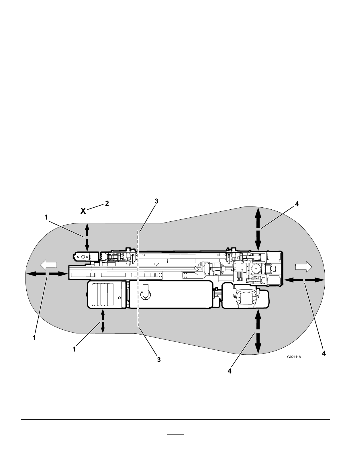
DrivingSafety
Youdrivethemachinetoandfromtheworksitewiththeuse
ofatetheredremote.Whendrivingthemachine,observethe
followingsafetyprecautions:
Thefollowingillustrationdisplaysthesafedistancethatall
individualsmustmaintainwhilemovingthemachine.
Figure1
DrivingDangerZone
1.1.8m(6ft)safetydistance
2.Operator4.2.4m(8ft)safetydistance
3.Turning-radiuscenter
2
g021118
Page 3
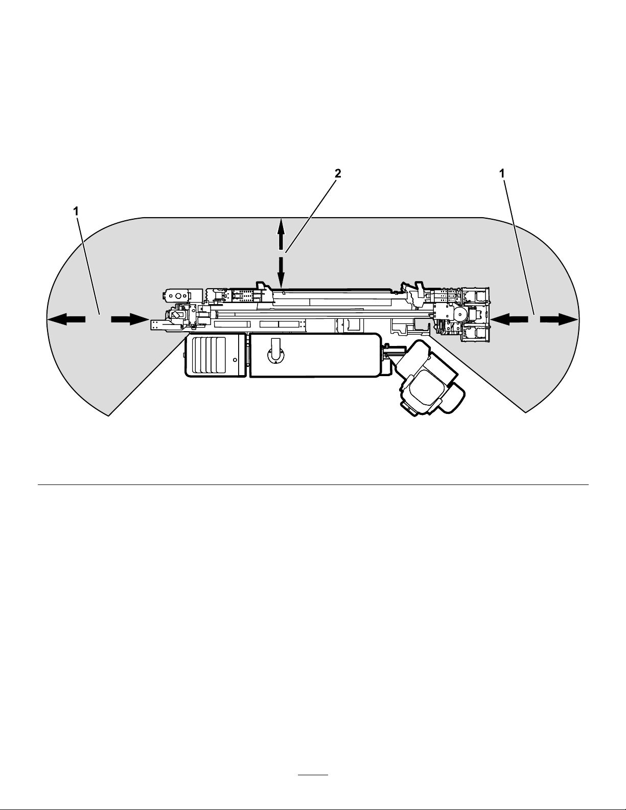
DrillingSafety
Ensurethatnooneapproachesapipewhileitisspinning.
Thepipecansnagonclothingandcauseamputationor
death.AlwaysengagetheExit-sideLockoutbeforeanyone
approachesthefrontofthemachine,bit,reamer,orpipe.
includeswhereapersoncanbereachedbyoperational
movementofthemachine,itsworkingdevices,auxiliary
equipment,orswinging/fallingequipment.
Note:Thedangerzonedenestheamountofspace
neededforsafedrillingoperation,includingmovementof
thecarriage.
DrillingDangerZone
Thedangerzoneistheareawithinandaroundthemachine
whereapersonisexposedtotheriskofinjury.Thisproximity
Thefollowingillustrationdisplaysthesafedistancethatmust
bekeptbyallindividualswhiledrilling.
Figure2
DrillingDangerZone
1.3m(10ft)safetydistance2.1.8m(6ft)safetydistance
DrillingNearUtilityLines
Whenworkingnearburiedutilitylines,safetyprecautions
mustbetaken.
Important:Beforeoperatinginanareawith
high-voltagelinesorcables,contacta“One-Call
SystemDirectory”service.IntheUSA,call811or
yourlocalutilitycompany.Ifyoudonotknowyour
localutilitycompany’sphonenumber,callthenational
number(USAandCanadaonly)at1-888-258-0808.Also,
contactanyutilitycompaniesthatarenotparticipants
ofthe“One-CallSystemDirectory”service.Please
refertoDrillingNearUtilityLines(page3)formore
information.
g194261
3
Page 4

UtilityLineColor
Refertothefollowingtablefortheproperutilitylineandthecorrespondingutilitylinecolor(USAandCanada).
UtilityLine
ElectricRed
Telecommunication,alarmorsignal,cables,orconduit
Naturalgas,oil,steam,petroleum,orothergaseousorammable
material
SeweranddrainGreen
DrinkingwaterBlue
Reclaimedwater,irrigation,andslurrylinesPurple
TemporarysurveymarkingsPink
ProposedexcavationlimitsWhite
ElectricalLineSafety
WARNING
Ifyouleavetheseatofthemachineortouch
anypartofthemachinewhenitischargedwith
electricity,seriousinjuryordeathcouldresult.
Donotleavetheseatofthemachineifthemachine
ischargedwithelectricity.
Intheeventofanelectricstrikethatchargesthemachine,the
Zap-AlertElectricStrikealarmsystemwillsoundforaslong
asthemachineischargedwithpower.
Note:Immediatelycontacttheproperemergencyandutility
authoritiestosecuretheareainthecasethatthemachineis
chargedandyoucannotleavetheseatofthemachine.
Note:Itispossibletostrikeautilitylinewithoutthemachine
becomingcharged.
•Thealarmwillsoundifthedrillcontactsanelectrical
powersource.
•Itislikely(butnotalwaysthecase)thatthepower-source
interrupterorbreakerwilltrip,buttoensureyoursafety,
considerthatthemachinemaybeconductingelectricity.
•Donotattempttoleavethemachine.
Note:Youwillbesafeaslongasyoudonotleavethe
seatofthemachine.
UtilityLineColor
Orange
Yellow
GasLineSafety
WARNING
Ifyoudamageagasline,animmediateexplosion
andrehazardcouldoccur.Leakinggasisboth
ammableandexplosiveandmaycauseserious
injuryordeath.
•Donotsmokewhileoperatingthemachine.
•Shutoffthemachineandremovethekey.
•Removeallindividualsfromtheworkarea.
•Immediatelycontacttheproperemergencyand
utilityauthoritiestosecurethearea.
WaterLineSafety
Ifyoudamageawaterline,apotentialoodhazard
couldoccur.
•Shutoffthemachineandremovethekey.
•Removeallindividualsfromtheworkarea.
•Immediatelycontacttheproperemergencyand
utilityauthoritiestosecurethearea.
CommunicationLineSafety
Important:RefertoElectricalLineSafety(page4)ifa
communicationlineisdamaged.
•Touchinganypartofthemachinemaygroundyou.
•Donotallowanotherindividualtotouchorapproach
themachinewhencharged.
•Thealarmmaysoundifacommunicationlineisbroken,
butuntilyouarecertain,youmustconsiderthealarmto
beanelectricstrike.
CAUTION
Ifyoudamagetheber-opticcableandlookinto
theexposedhighly-intenselight,youmayharm
youreyes.
•Shutoffthemachineandremovethekey.
•Removeallindividualsfromtheworkarea.
•Immediatelycontacttheproperemergencyand
utilityauthoritiestosecurethearea.
4
Page 5

MaintenanceandStorage
•Donottouchpartswhichmaybehotfromoperation.
Allowthemtocoolbeforeattemptingtomaintain,adjust,
orservice.
•Lowerthethrustframe,stoptheengine,andremove
thekey.Waitforallmovementtostopbeforeadjusting,
cleaning,orrepairing.
•Cleandebrisfromattachments,drives,mufers,and
enginetohelppreventres.Cleanupoilorfuelspillage.
•Lettheenginecoolbeforestoringanddonotstorenear
ame.
•Donotstorefuelnearamesordrainindoors.
•Parkthemachineonlevelground.
•Donotallowuntrainedpersonneltoservicethemachine.
•Carefullyreleasepressurefromcomponentswithstored
energy.
•Keephandsandfeetawayfrommovingparts.Ifpossible,
donotmakeadjustmentswiththeenginerunning.
•Disconnectthebatterybeforemakinganyrepairs.
Disconnectthenegativeterminalrstandthepositive
last.Reconnectpositiverstandnegativelast.
–Donotstorethemachineorfuelcontainerinside
wherethereisanopename,suchasnearawater
heaterorfurnace.
–Donotllacontainerwhileitisinsideavehicle,
trunk,pick-upbed,oranysurfaceotherthanthe
ground.
–Keepcontainernozzleincontactwiththetankduring
lling.
•UseonlygenuineTororeplacementpartstoensurethat
originalstandardsaremaintained.
•Keepyourbodyandhandsawayfrompinholeleaks
ornozzlesthatejecthighpressurehydraulicuid.Use
cardboardorpapertondhydraulicleaks;donotuse
yourhands.Hydraulicuidescapingunderpressurecan
penetrateskinandcauseinjuryrequiringsurgerywithina
fewhoursbyaqualiedsurgeonorgangrenemayresult.
•Chargebatteriesinanopen,wellventilatedarea,away
fromsparkandames.Unplugthechargerbefore
connectingordisconnectingitfromthebattery.Wear
protectiveclothinganduseinsulatedtools.
•Batteryacidispoisonousandcancauseburns.Avoid
contactwithskin,eyes,andclothing.Protectyourface,
eyes,andclothingwhenworkingwithabattery.
•Batterygasescanexplode.Keepcigarettes,sparksand
amesawayfromthebattery.
•Keepallpartsingood-workingconditionandallhardware
tightened.Replaceallwornordamageddecals.
•Ifanymaintenanceorrepairrequirestheframetobein
theraisedposition,securetheframeintheraisedposition
withthehydrauliccylinderlock.
•Keepnutsandboltstight.
•Keepequipmentingoodcondition.
•Donottamperwithsafetydevices.
•Keepthemachinefreeofgrass,leaves,orotherdebris
build-up.Cleanupoilorfuelspillage.Allowthemachine
tocoolbeforestoring.
•Useextracarewhenhandlingfuels.Theyareammable
andvaporsareexplosive.
–Useonlyanapprovedcontainer.
–Donotremovethefuelcaporaddfuelwhenthe
engineisrunning.Allowtheenginetocoolbefore
refueling.Donotsmoke.
–Donotrefuelthemachineindoors.
5
Page 6
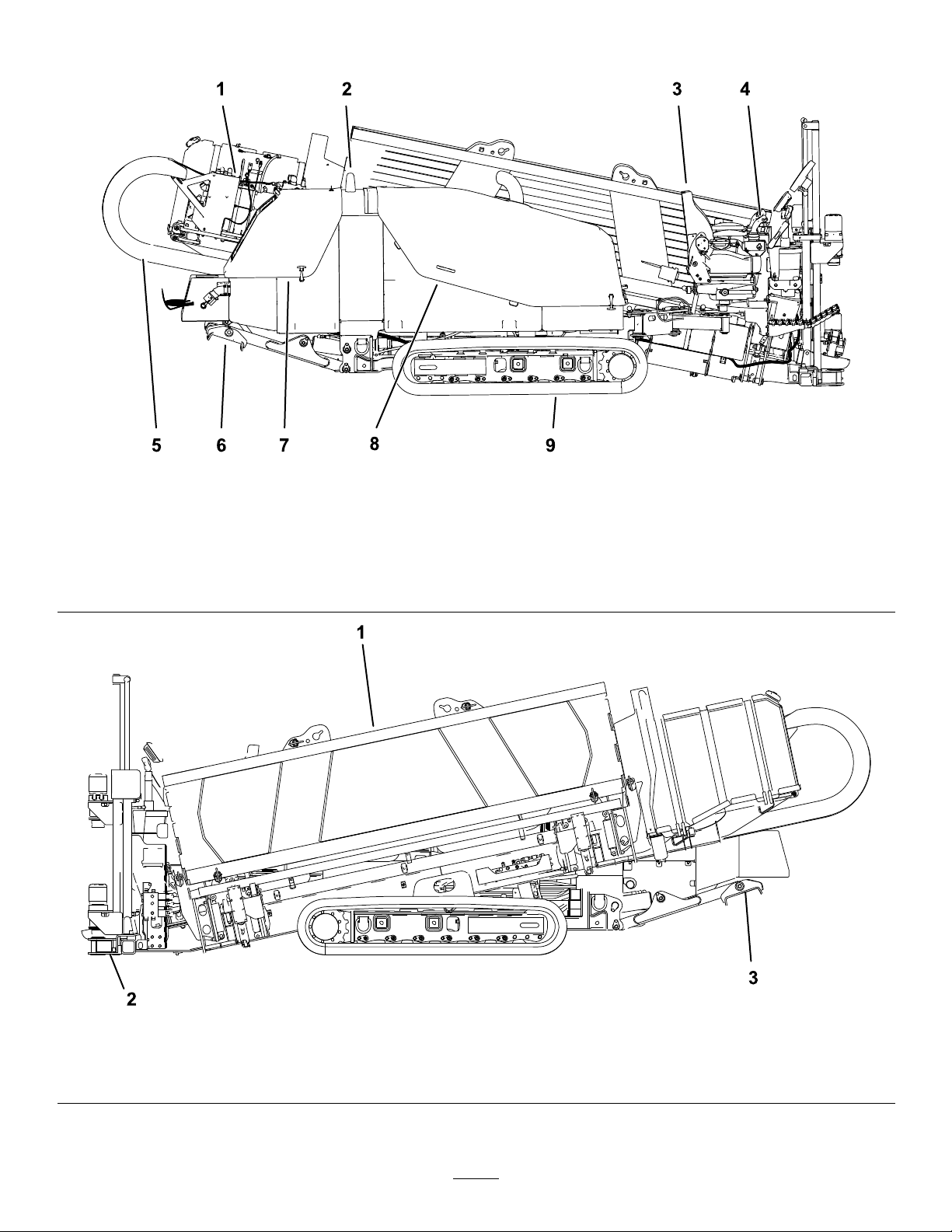
ProductOverview
g194439
Figure3
1.Drillcarriage
2.Zapalertstrobe7.Rearhood
3.Operatorseat
4.Controlpanel
5.Thrustframe
6.RightStabilizer
8.Fronthood
9.Track
1.Pipeholder
2.Stakedownplate
g194440
Figure4
3.Leftstabilizer
6
Page 7
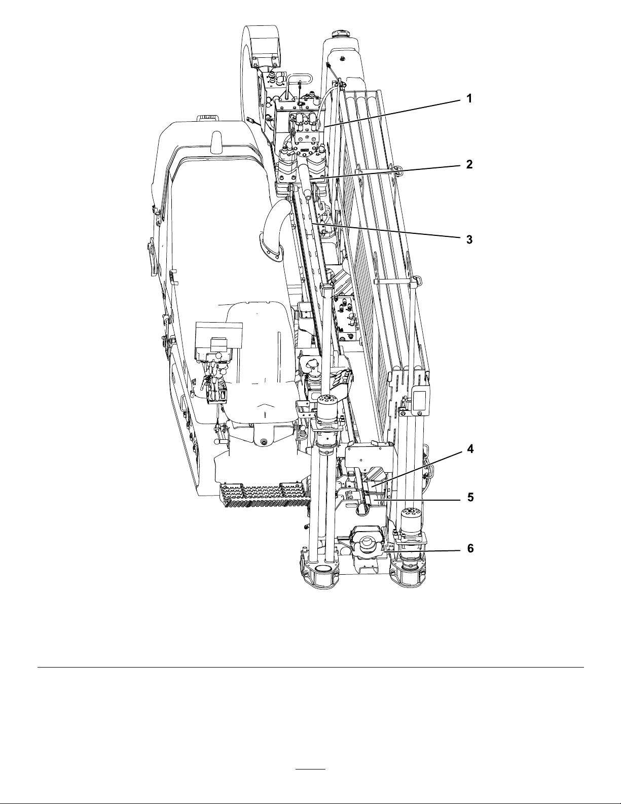
Figure5
1.Drillcarriage4.Upperwrench
2.Drillspindle5.Lowerwrench
3.Thrustframe
6.Pipewiper
7
g194441
Page 8

Operation
Youdrilltheboreinthreestages:
A.Entry
UnderstandingHorizontal DirectionalDrilling
Horizontaldirectionaldrillingisaprocessusedfordrillinga
horizontalborethroughthesoilandunderobstructionssuch
asroads,buildings,bodiesofwater,etc.Onceyoudrillthe
bore,youpullbacktheutilitylinesorpipesthroughthebore
andconnectthemasneeded.Becauseitdoesnotrequire
verymuchdisturbanceofthesurface,installationofutilities
usingdirectionaldrillingpreservestheenvironmentandsaves
bothtimeandmoneyovertraditionalinstallationmethods
suchastrenching.
Wheninstallingcablingorpipeusingadirectionaldrill,you
completethefollowingsteps:
1.Gathersiteinformation.
Beforeoperatinginanareawithhigh-voltagelinesor
cables,contacta“One-CallSystemDirectory”service.
IntheUSA,call811oryourlocalutilitycompany.If
youdonotknowyourlocalutilitycompany’sphone
number,callthenationalnumber(USAandCanada
only)at1-888-258-0808.Also,contactanyutility
companiesthatarenotparticipantsofthe“One-Call
SystemDirectory”service.PleaserefertoDrilling
NearUtilityLines(page3)formoreinformation.
Beforefullyplanningthebore,youmustgather
informationaboutthejobsitesuchasthelocationof
otherutilities,obstaclesatthesite,andwhatregulations
andpermitsyouwillneedtocompletethejob;referto
GatheringSiteInformation(page9).
2.Planthebore.
Beforeyoucandrill,youmustrstplantheborepath
basedontheinformationyougathered.Referto
PlanningtheBorePath(page11).
3.Preparethejobsiteandthemachine.
Beforedrilling,youpreparethejobsitewithanentry
point,depth-gaugehole(optional),andanexithole.
Youalsoneedtodrivetheunittothesite,setitupfor
drilling,andconnectittoadrilling-uidmixer.
Intheentryphaseofthebore,youpushthedrill
bitandheadintothegroundatanangleofupto
16degrees.Afterpushinginoneormorepipes,
youbegindrillingdownandforwarduntilyou
reachthedesireddepthordepth-gaugehole(if
used).
B.HorizontalReach
Afterreachingthedesireddepth,youpushthe
bitforward,steeringthebittoahorizontaldepth.
Thedrillbitemitsaradiosignalfromthesonde
housing,whichallowsacrewmemberonthe
surfacetotrackthelocationanddepthofthehead
usingthesondereceiverasyoudrillandsteerit
alongaplannedroute.
C.Exit
Onceyouhaveattainedtheplannedhorizontal
reach,yousteertheheadupatananglesimilar
toyourentryanglebringingthebitintotheexit
holeortrench.
RefertoDrillingtheBore(page25).
5.Backreamtheboreandpullbackthecablingor
pipe.
Afterenteringtheexithole,theendcrewdetachesthe
drillbitandsondehousingfromthedrillpipe.Inits
place,theyattachareamingbitandtheendofthecable
orpipetobepulledthroughthebore.Thereaming
bitisdesignedtoenlargetheboreasyoupullitback.
Asbefore,youpumpdrillinguidthroughthepipe
tothereamingbitasyoupullthecableorpipeback
throughtheboretolubricatethereamerandallow
thecableorpipetoslideeasilythroughthebore.You
continuepullingthepipebackuntilthereamerreaches
thedepth-gaugeholeorexitsattheentrypoint.There
youremovethereamerandproductfromthedrillpipe,
pullingthepipetherestofthewaybacktothemachine.
RefertoBackreamingandPullback(page28)for
instructionsonbackreamingandpullingcableorpipe.
6.Finishtheboreandleavethejobsite.
Note:Whendrilling,youconnectthemachinetoa
drilling-uidmixerthatmixeswaterwithbentonite
clayandotheringredients.Themachinepumpsthis
mixture,referredtoasdrillinguidor“Mud”,through
thedrillpipeandoutthedrillbit.Thedrillinguid
lubricatesthebit,helpstoholdtheboreopenwhile
drilling,andmixeswiththespoils,ushingthemout
oftheborethroughtheentrypoint.
RefertoPreparingtheJobSiteandtheMachine(page
18)forinstructionsonpreparingthejobsiteandthe
machine.
4.Drillthebore.
Aftercompletingtheoperation,youneedtodisconnect
andcleanthemachineandloaditonthetrailer;refer
toFinishingtheJob(page30).
8
Page 9

GatheringSiteInformation
PlanningtheInitialRoute
Beforeyoucanbeginboring,youneedtoplantherouteyou
willboreandprepareasfollows:
•Createabasicplanforthebore,mappingoutthe
proposedroute.
–Noteanyobstacleswhichmayaffecttheboresuchas
largetrees,bodiesofwater,buildings,etc.
–Plantherouteoftheboretoavoidasmanyobstacles
aspossible.
–Determinethedepthofanybodiesofwatertobe
crossedtoensurethatyoucangetdeepenoughunder
them.
•Determinethedepthyouneedtoinstallthematerialat
andtheminimumbendradiusbothofthedrillpipeand
ofthematerialbeinginstalled.Thiswillseriouslyaffect
howlongtheboreneedstobeandatwhatangleyoucan
beginandend;refertoPlanningtheBorePath(page11).
•Havetheareaoftheboremarkedforutilitylines(inthe
UScall811).Ensurethatalllinesaremarkedonyour
blueprints/boreplanaswell.
•Contactthelocalauthoritiestoarrangeforanypermits
andtrafccontrolthatyouwillneedtoconductthejob.
InspectingtheProposedJobSite
Physicallyinspectthesiteasfollows:
•Notetheterrain,slopes,valleys,hills,andanyfeatures
notplannedforpreviously.
Determinethedegreeofslopeatboththeproposedentry
pointandexitpoint.
•Determinewhatthesoiltypesareintheareaand,if
possible,whattheyareatthedepthyouwillbeboring.
Youmayneedtodigtestholesatintervalsalongthebore
pathtofullydeterminethis.
•Walktheareaoftheborelookingforanypossible
unmarkedobstructions.Lookformanholes,pedestals,
oldfoundations,etc.
•Identifyallhazardsofwhichyouwillbepassingwithin
3m(10ft).
DANGER
Contactingundergroundhazardswiththe
machinewhiledrillingorreamingcancause
explosion,electrocution,breathingproblems,
severetrauma,anddeathtoyouorbystanders.
–Ensurethatallpersonnelatthejobsitewear
personalprotectiveequipmentincluding
ahardhat,eyeprotection,andhearing
protection.
–Keepbystandersandspectatorsawayfrom
thejobsite,includingthecompletebore
path.
–Locateandexposeallelectricandgaslines
thatyouwillbecrossingbycarefulhand
digging.
–EnsurethatyouusetheZap-Alertsystem
wheneveroperatingthemachine.
Commonhazardsincludethefollowing:
–Gaslines
DANGER
Drillingintoagaslinecancauseanexplosion
orre,burning,injuring,orkillingyouor
othersinthevicinityofthebreak.
◊Donotsmokeorhaveanysourceofame
neargaslinesorateitherendofabore
thatwillbecrossingagasline.
◊Keepbystandersandspectatorsaway
fromthejobsite,includingthecomplete
borepath.
◊Locateandexposeallgaslinesthatyou
willbecrossingbycarefulhanddigging.
◊Havethegascompanyturnoffthegas
toanylinesyouwillbecrossingbefore
drilling.
◊Usethereceivertotracktheexactposition
ofthedrillheadwhenapproachinggas
lines.
9
Page 10

–Electricalpowerlines
DANGER
Drillingintoanelectricpowerlinewillcause
themachinetobecomeelectriedandmay
electrocuteyouoranybystanders.
–Crystallinesilicaandotherdust
Ifyouwillbedrillingthroughorcuttingconcrete,
sand,orothersubstancesthatcreatedustsorfumes,
youneedtoensurethatyouandallworkerswear
breathingprotectiontoprotectyourlungsfromthe
dust.
◊Keepbystandersandspectatorsaway
fromthejobsite,includingthecomplete
borepath.
◊Locateandexposeallelectriclinesthat
youwillbecrossingbycarefulhand
digging.
◊Havetheelectriccompanyturnoffthe
powertoanylinesyouwillbecrossing
beforedrilling.
◊Usethereceivertotracktheexact
positionofthedrillheadwhen
approachingelectriclines.
◊Beforedrilling,setupandusethe
Zap-Alertsystemwhichisdesignedto
notifyinthecaseofanelectricstrikeand
electricallyisolatethemachineoperator
fromthemachine.IftheZap-Alertalarm
triggers,stopwhatyouaredoinganddo
notleavetheoperator’sposition.Refer
toDeployingtheZap-AlertSystem(page
24)fordetailedinstructionsonusingthe
Zap-Alertsystem.
WARNING
Machiningorhandlingstone,masonry,
concrete,metal,andothermaterialscan
generatedust,mists,andfumescontaining
chemicals,suchassilica,knowntocause
seriousorfatalinjuryorillness,suchas
respiratorydisease,silicosis,cancer,birth
defects,orotherreproductiveharm.
◊Controldust,mist,andfumesatthe
sourcewherepossible.Watershouldbe
usedfordustsuppressionwhenfeasible.
◊Usegoodworkpracticesandfollowthe
recommendationsofthemanufactureror
suppliers,OSHA,andotheroccupational
andtradeassociations.
◊Whenthehazardsfrominhalationcannot
beeliminated,theoperatorandany
bystandersshouldweararespirator
approvedbyOSHAforthematerialbeing
handled.
WARNING
Silicosis W ar ning:
drillingstone,masonry,concrete,metal,
andothermaterialswithsilicaintheir
compositionmaygiveoffdustormist
containingcrystallinesilica.Silicaisa
basiccomponentofsand,quartz,brick,
clay,granite,andnumerousotherminerals
androcks.Repeatedand/orsubstantial
inhalationofairbornecrystallinesilicacan
causefatalrespiratorydiseases,including
silicosis.Inaddition,someotherauthorities
havelistedrespirablecrystallinesilicaasa
substanceknowntocausecancer.When
cuttingsuchmaterials,followrespiratory
precautions.
Grinding,cutting,or
10
Page 11

PlanningtheBorePath
1
2
3
4
5
g021764
Beforesettingupthejobsite,youneedtoplantheborepath,
includingthefollowing:
g021764
Figure6
1.Boreentry
2.Beginning-of-bore-at-depthpoint5.End-of-bore-at-depthpointandboreexit
3.Boredepth
•Boreentry
Theisthelocationwhereyousetupthemachineandthe
drillbitenterstheground.Dependingonconditions,this
willtypicallybesetback9to15m(30to50ft)fromthe
beginning-of-the-bore-at-depthpoint.
•Beginning-of-bore-at-depthpoint
Thisisthepointwhereyouwanttheutilitylineorpipeto
endafterinstallationiscomplete.Itistypicallythepointat
whichtheborelevelsoutandbeginstoborehorizontally .
Thismaybethesameastheentrypoint,oryoumaydiga
separatedepth-gaugeholeatthispoint(Figure6).
•Boredepth
Thisthedepthatwhichyouwanttoinstalltheutility
lineorpipe.Thismachineisdesignedprimarilyfor
installationsbetween1and3m(3.5to10ft).
•Obstaclesinthepath
Itisimportanttoknowwheretheknownobstaclesare
thatyouwillneedtosteeraroundorunderbeforestarting
sothatyoucanplanwheretobeginsteeringpriorto
reachingtheobstacle.
•End-of-bore-at-depthpoint
Thisisthepointwhereyouwanttheutilitylineorpipe
tobeginafterinstallationiscomplete.Oftenthiswillalso
betheboreexit.
4.Obstacle
neededforsteeringthedrilltothesurface,typically9to15
m(30to50ft)fromtheend-of-the-bore-at-depthpoint.
DeterminingtheBoreEntryPoint
Oneofthemorechallengingaspectsofplanningthebore
pathistodeterminetheentrypointofthebore.Youneedto
takethefollowingtraitsintoaccountwhendeterminingthe
locationoftheentrypoint:
•Boredepth
Thisthedepthatwhichyouwanttoinstalltheutility
lineorpipe.Thismachineisdesignedprimarilyfor
installationsbetween1and3m(3.5to10ft).
•Pipeandmaterialexibility
The3m(10ft)pipesusedonthismachinecanextoan
8%pitchoverthelengthofthepipe;thisequatestoa
bendofnomorethan20cm(8inches)offofastraight
path(Figure7).
Important:Ifyousteerthepipetobendsharper
than20cm(8inches)perpipe,youmaydamagethe
pipesandtheirconnections.Y oumustalsomake
steeringchangesgraduallyovertheentirelengthof
eachpipe.Ifyousteerthewhole20cm(8inches)
inonly25to50cm(1to2ft)oftravel,youwill
permanentlydamagethepipes.
•Boreexit
Thisisthelocationwherethedrillheadwillexitthe
groundandthepointatwhichyouwillpulltheutilitylines
orpipeintothebore.Ifthispointwillbeatthesurface
insteadofatinstallationdepth,youwillneedtodetermine
thedistancefromtheend-of-bore-at-depthlocation
11
Page 12

1
g021765
Figure7
1
2
3
g021766
2
3
g021767
1
1.20cm(8inches)
Thisexibilityisoftenratedinmaterialsasaminimum
bendradius,whichistheradiusofthecircleformedifthe
materialorpipes,connectedtogether,werebenttoform
agiantcircle.Theminimumradiusofacirclemadewith
thepipeusedwiththismachineis36.6m(102ft).
g021765
•Entrypitch
Theentrypitchistheangleatwhichthemachine
enterstheground.Withthetracksonlevelground,the
stabilizersdown,andthestake-downplateontheground,
thedrillframeangleisabout15degreesora27%pitch.
Thispitchwillchangedependingontheslopeofthe
groundandotherfactorsofthejobsite.Youcanalso
reducethispitchabitbybuildingupthegroundunder
thestake-downplatebeforepositioningthemachine.
Youcandeterminetheactualpitchofthedrillframeby
placingthedrillbitandsondehousingontheframeand
thenusethereceivertodisplaythepitch.
Thesteeperyourentrypitchis,thedeeperyourborewill
havetobeduetothelimitationsofthepipeexibility.
Typicallyyouneedtoinsertthedrillandatleast1/3ofa
pipeintothegroundbeforeyoucanstartsteeringtoward
thebeginningoftheborepoint.Figure8,Figure9,and
thefollowingtableillustratetherelationshipbetween
entrypitchanddepth.
g021767
Figure9
1.18%pitch3.53cm(21inches)
2.3m(10ft)
Figure8
1.26%pitch3.76cm(30inches)
2.3m(10ft)
g021766
12
Page 13

Note:Thedepthsgiveninthefollowingtablearefor3m(10ft)ofcombineddrillheadandpipe.Asyousteerup,the
pitchofthesteeredsectionwillchangeandcanbemonitoredwiththereceiver.Usethefollowingtabletoidentifyhow
manylengthsofpipewillbenecessarytoinsertandsteertothebeginningpointandhelpyouchooseanentrypoint.
Pitch
1%2cm(1inch)26%76cm(30inches)
2%5cm(2inches)27%79cm(31inches)
3%10cm(4inches)28%81cm(32inches)
4%13cm(5inches)29%84cm(33inches)
5%15cm(6inches)30%86cm(34inches)
6%18cm(7inches)31%91cm(36inches)
7%20cm(8inches)32%94cm(37inches)
8%25cm(10inches)33%97cm(38inches)
9%28cm(11inches)34%99cm(39inches)
10%30cm(12inches)35%102cm(40inches)
11%33cm(13inches)36%104cm(41inches)
12%36cm(14inches)37%107cm(42inches)
13%39cm(15inches)38%109cm(43inches)
14%43cm(17inches)39%112cm(44inches)
15%46cm(18inches)40%114cm(45inches)
16%48cm(19inches)41%117cm(46inches)
17%51cm(20inches)42%117cm(46inches)
18%53cm(21inches)43%119cm(47inches)
19%56cm(22inches)44%122cm(48inches)
20%61cm(24inches)45%124cm(49inches)
21%64cm(25inches)46%127cm(50inches)
22%66cm(26inches)47%130cm(51inches)
23%69cm(27inches)48%133cm(52inches)
24%71cm(28inches)49%135cm(53inches)
25%74cm(29inches)50%137cm(54inches)
Allmeasurementsareapproximateandwillvarydependingonsoilconditions.
DepthChangeper10feet
Pitch
DepthChangeper10feet
Note:ThesevaluesandmorecanbefoundintheDriller’sHandbook&DailyLogbyDigitalControlIncorporated.
13
Page 14

Giventheaboveinformation,youcancalculatethenumberof
1
4
2
3
5
g021768
7
6
rodsrequiredtoreachyourbeginningpointattheappropriate
depth.Tororecommendsthatyoustarttheentrypointa
distancebackfromyourbeginning-at-depthpointbythe
samedistanceasthelengthofpipesyouwillneedtoreach
thatpoint.Thiswillensurethatyouhaveenoughextraspace
soyouwillnotneedtoover-steeranddamagethepipes.
Thefollowingexampleillustratestheprocessgivenan
installationusingthemaximumentrypitchofthemachine
(26%)onlevelground:
•Youinserttherst3m(10ft)ofdrillbit/pipeintothe
groundwithnosteering.Theendofthedrillbitwillbe
76cm(30inches)deep(Figure7).
g021768
Figure10
1.26%pitch4.185cm(73inches)7.14.7m(45ft)
2.76cm(30inches)5.203cm(80inches)
3.142cm(56inches)6.208cm(82inches)
•Youbeginsteeringupforthenext3m(10ft),pushingthe
pipesinatthemaximumpitchchangeof8%.Thisresults
inachangeofpitchfrom26%atthebeginningofthe3m
(10ft)to18%attheendofthe3m(10ft)foranaverage
pitchof22%.Giventhat,thedrillheadlowersanother66
cm(26inches)andisnow142cm(56inches)deep.
•Continuingsteeringupforthenext3m(10ft)atan8%
pitchchange,yourpitchwillchangefrom18%to10%
foranaveragepitchof14%.Giventhat,thedrillhead
lowersanother43cm(17inches)andisnow185cm(73
inches)deep.
•Continuingsteeringupforthenext3m(10ft)atan8%
pitchchange,yourpitchwillchangefrom10%to2%for
anaveragepitchof6%.Giventhat,thedrillheadlowers
another18cm(7inches)andisnow203cm(80inches)
deep.
•Levelingthedrillheadfrom2%to0%takeslessthan1.5
m(5ft)moreforanaldepthof208cm(82inches).
Reachingthisnalpointtookfourandahalf,3m(10ft)
pipes.Soforthisexampleyourentrypointshouldbe
14.7m(45ft)backfromthebeginning-at-depthpointof
yourinstallation.
14
Page 15

Thefollowingexampleillustratestheprocessgivenan
1
2
3
4
g021769
6
5
installationusingthemachineatan18%pitchonlevel
ground:
1.18%pitch3.96cm(38inches5.119cm(47inches)
2.53cm(21inches)4.114cm(45inches)6.10.6m(35ft)
•Youinserttherst3m(10ft)ofdrillbit/pipeintothe
groundwithnosteering.Theendofthedrillbitwillbe
53cm(21inches)deep(Figure11).
Figure11
g021769
•Youbeginsteeringupforthenext3m(10ft),pushingthe
pipesinatthemaximumpitchchangeof8%.Thisresults
inachangeofpitchfrom18%atthebeginningofthe3m
(10ft)to10%attheendofthe3m(10ft)foranaverage
pitchof14%.Giventhat,thedrillheadlowersanother43
cm(17inches)andisnow96cm(38inches)deep.
•Continuingsteeringupforthenext3m(10ft)atan8%
pitchchange,yourpitchwillchangefrom10%to2%for
anaveragepitchof6%.Giventhat,thedrillheadlowers
another18cm(7inches)andisnow114cm(45inches)
deep.
•Levelingthedrillheadfrom2%to0%takeslessthan1.5
m(5ft)moreforanaldepthof119cm(47inches).
Reachingthisnalpointtookthreeandahalf,3m(10
ft)pipes.Soforthisexampleyourentrypointshouldbe
10.6m(35ft)backfromthebeginning-at-depthpointof
yourinstallation.
Important:Y oucanusetheinformationcontainedin
thissectiontodetermineboththespaceneededtosteer
uptotheexitpointifneededandalsotosteeraround
obstacles.
MappingtheBore
Withtheinformationyougatheredpreviously,mapoutthe
routeofthebore,identifyingthefollowingsothatyoucan
markthesitelater:
•Entrypoint
•Locationofthemachineandsupportingequipment
•Beginningofboreatdepth
•Anyobstaclesthatyouneedtosteeraroundandthe
locationswhereyouneedtostartsteeringtogetaround
orunderthem
•Anyutilitylinesyouwillneedtocross
•Slopeandsoilchangesalongthepaththatwillaffectthe
bore
•Endoftheboreatdepth
•Exitlocationifdifferentthantheendofthebore
15
Page 16

UnderstandingandUsing
ON
OFF
1
2
3
4
5
G022151
ON
OFF
1
2
3
4
5
G022151
theExit-side-lockoutSystem
buttonsendsasignaltothereceiverthatallowsthemachine
operatortoresetthesystemandrestorethethrustandrotary
functions.
(StandardRange)
Exit-side-lockoutSystem(Standard
Range)
Theexit-side-lockoutsystemprovidestheindividualsworking
aroundthemachinewithameanstodisablethedrillpipe
fromrotatingandthrusting.
Thissystemconsistsofareceivermountedonthemachine
andatransmitter(Figure12)thatmustbeheldbyadesignated
individualworkingaroundthemachine.
Thefollowingtableliststhevariousstatesoftheindicator
lightsonthehandheldtransmitter(Figure13)andtheir
meanings:
Figure13
1.Redindicatorlight
2.Yellowindicatorlight
3.Greenindicatorlight
4.Onbutton
5.Offbutton
g022151
g022151
Figure12
1.Redindicatorlight
2.Yellowindicatorlight
3.Greenindicatorlight
4.Onbutton
5.Offbutton
UnderstandingandUsingtheHandheld
Transmitter(StandardRange)
TheindividualholdingthetransmittercanpushtheLock
Drill(Off)buttontostopthedrillrotationandthrust.This
isprimarilyusedtostop/lockoutthedrilloperationsinthe
followingsituations:
•Wheninstallingorremovingadrillheadorreamer
•Wheneversomeoneneedstoapproachthedrillpipeor
headanywhereinfrontofthemachine
•Placingawiperonthedrillpipe
•Whenthelocationreceiveroperatoridentiesaproblem
requiringimmediateshutdownofdrilling
Whenitissafetoresumedrilling,theindividualholdingthe
transmittercanpresstheUnlockDrill(On)button.This
16
Page 17

IndicatorLightState
Greenlightisblinkingrapidly
Greenlightisilluminated
withoutblinking
YellowlightisblinkingslowlyThebatteriesarelow;change
RedlightisblinkingThetransmitterisactively
Meaning
Thetransmitteristransmitting
tothebaseunit
Abuttononthetransmitteris
currentlypressed
thebatteries.Ifyoudonot
changethebatteriessoon,the
handheldwillpowerdown.
receivingmessagesfromthe
baseunit.
ReplacingtheHandheldTransmitter
Batteries(StandardRange)
Important:Ensurethatyouinstallthebatteries
inthecorrectpolarityorientationoryoucould
damagethetransmitter.
1.Loosenthe4screwssecuringthebatterycover(Figure
14).
Figure14
1.Handheldtransmitter
2.Batterycover
3.Screws
2.Removethecover(Figure15).
g023889
Figure16
1.Handheldtransmitter2.AAAbatteries
5.Replacethecoverandsecureitwiththescrewremoved
previously.
Tightenthescrewsenoughtoensurethatthesealing
gasketiscompressed,butdonotovertightenthem.
AssociatingtheHandheldTransmitter
withtheBaseUnit(StandardRange)
g023887
Ifthehandheldtransmittereverstopscommunicatingwith
thebaseunit,orifyoureplaceitwithanewtransmitter,you
needtoassociatethetransmittertothebaseunitasfollows:
1.Ensurethatthemachineisturnedoff.
2.Ensurethatthehandheldtransmitterisnotactive(i.e.,
nolightsareon).
3.Standneartherearcontrolpanelofthemachine.
4.SimultaneouslypressandholdtheOnandOffbuttons.
TheGreenlightilluminates.
5.ContinueholdingthebuttonsuntiltheY ellowlight
beginsashing,thenreleasethebuttons.
Figure15
1.Handheldtransmitter2.Batterycover
3.Removetheexistingbatteries.
4.Install3new,AAAbatteriesintheorientationshown
inFigure16.
TheRedlightbeginsashingallowingyou2seconds
topressthenextbutton.
6.PressandholdtheOnbutton
g023888
TheRedlightturnsoffandtheGreenandYellow
lightsilluminate.
Important:Ifyoudonotpressthisbuttonwithin
2seconds,youwillhavetostartthisprocedure
overagain.
7.ContinueholdingtheOnbuttonandturnonthe
machinetopowerthebaseunit.
Thebaseunitandhandheldestablishacommunication
linkwhileyouholdthebutton.Oncetheprocessis
17
Page 18

complete,theYellowlightturnsoff,theRedlight
beginsashing,andtheGreenlightilluminates.All
lightsremainasmentioneduntilyoureleasethebutton.
PreparingtheJobSiteandthe Machine
8.ReleasetheOnbutton.
TheRedlightturnsoffandtheGreenlightashesfor
afewseconds.
DisassociatingallHandheld
TransmittersfromtheBaseUnit
(StandardRange)
Important:Completingthisprocedurewilldisassociate
alltransmittersfromthebaseunit,whichwillneedtobe
associatedagainbeforetheywillfunction.
1.Ensurethatthemachineisturnedoff.
2.Ensurethatthehandheldtransmitterisnotactive(i.e.,
nolightsareon).
3.Standneartherearcontrolpanelofthemachine.
4.SimultaneouslypressandholdtheOnandOffbuttons.
TheGreenlightilluminates.
5.ContinueholdingthebuttonsuntiltheY ellowlight
beginsashing,thenreleasethebuttons.
TheRedlightbeginsashingallowingyou2seconds
topressthenextbutton.
6.PressandholdtheOffbutton
TheRedlightturnsoffandtheGreenandYellow
lightsilluminate.
Beforedrilling,preparethejobsiteandmachineasfollows:
•MarkandpreparetheborepathPlanningtheBorePath
(page11).
•TesttheZap-Alertsystem;refertoTestingtheZap-Alert
System(page19).
•Loadthedrillpipesintothepipeholderifneeded.
•Addfueltothemachine;refertoAddingFuel(page20).
•Checktheoillevelintheengine.
•Checktheenginecoolantlevel.
•Checkthehydraulicoillevel.
•Checktheoillevelinthedrilling-uidpump.
•Load/unloadthemachine;refertoLoadingand
UnloadingtheMachine(page22).
•Drivethemachinetotheentrypoint;referto
UnderstandingHorizontalDirectionalDrilling(page8).
•Connectthemachinetoadrilling-uidsource;referto
ConnectingtoaDrilling-uidSource(page23).
•Setupthedrillbit(s)andtrackingelectronics;referto
SettingUptheDrillHeadandTrackingSystem(page22).
•Setupthemachinefordrilling;refertoSettingupthe
MachineforDrilling(page23).
•DeploytheZap-Alertsystem;refertoDeployingthe
Zap-AlertSystem(page24)
Important:Ifyoudonotpressthisbuttonwithin
2seconds,youwillhavetostartthisprocedure
overagain.
7.ContinueholdingtheOffbuttonandturnonthe
machinetopowerthebaseunit.
Thebaseunitandhandheldestablishacommunication
linkwhileyouholdthebutton.Oncetheprocessis
complete,theYellowlightturnsoff,theRedlight
beginsashing,andtheGreenlightilluminates.All
lightsremainasmentioneduntilyoureleasethebutton.
8.ReleasetheOffbutton.
TheRedlightturnsoffandtheGreenlightashesfor
afewseconds.
18
Page 19

TestingtheZap-AlertSystem
TheZap-Alertsystemisanelectricstrikesensingdeviceon
themachinethattriggersastrobelightandaudiblealarmin
theeventthatthedrillbit,reamer,orstakebreaksintoan
energizedpowerline.Intheeventofanelectricstrike,the
machinewillbecomeenergized,settingoffthealarm.
DANGER
IftheZap-Alertsystemactivateswhiledrilling,the
machine,exceptfortheoperator’splatform,will
becomeenergized.Ifyoustepofftheoperator
platformorifsomeonetouchesthemachineorwet
groundnearthemachineorinthebore,youor
theycouldbeelectrocutedcausingseriousinjury
ordeath.
•TesttheZap-Alertsystembeforedrilling.
•Deploythegroundingstakebeforedrilling.
Ensurethatthestakeisfullyinsertedintomoist
soil.
•IftheZap-Alertistriggered:
–Stayintheseatanddonottouchtheground
oranyotherpartofthemachineuntilthe
powerhasbeenturnedoff.Donotpour
liquidsorurinatefromtheoperatorplatform
ontotheground.
–Stopdrilling,stopthedrilling-uidow,and
retractthedrilloutoftheground.
–Keepeveryoneawayfromthemachine.
–Keepstandingorrunningwateranddrilling
uidcontainedclosetothemachine.Keep
wateranddrillinguidsourcesawayfrom
thebrokenline.
–Contacttheutilitycompanytohavepower
shutofftothebrokenline.Donotresetthe
Zap-Alertsystemuntilthepowerhasbeen
turnedoff.
g023074
Figure17
1.Testbutton5.Resetbutton
2.Zap-alerttester6.Alligatorclips
3.Zap-alertsystem7.Machinegroundingpoint
4.Zap-alertsystem
groundingstud
4.Connecttheotheralligatorcliptoametalcomponent
ofthemachineframe.
5.PresstheTestbuttonontheZap-Alerttester(Figure
17).
TheZap-Alertalarmshouldsound,andthestrobeon
topofthefronthoodshouldash.
6.PresstheZap-Alertresetbuttontostopthealarm
(Figure17).
TesttheZap-Alertsystembeforeusingthedrilleachday ,as
follows:
1.Openthefronthood.
2.Laythegroundingstakeatonthegroundawayfrom
themachine.Donotdrivethestakeintotheground.
Important:Donotallowthestaketotouchany
partofthemachine.
3.ConnectanalligatorclipfromtheZap-Alerttesterto
thegroundingstudontheZap-Alertsystem(Figure
17).
19
Page 20

7.Disconnectthealligatorclipsfromthegroundingstud
andthemachine.
8.Storethegroundingstakeintheholderontheoperator
platformasshowninFigure18.
Figure18
Ifeithertheaudiblealarmorthestrobelightfailedto
triggerwhenyoupressedthetestbutton,havethem
repairedbeforedrillingwiththemachine.
MountingaFireExtinguisher
Mountyourreextinguisher.
Note:Areextinguisherisnotprovidedwiththemachine.
Therecommendedreextinguisherisadrychemicalre
extinguisherapprovedforclassBandCres.
WARNING
Fuelisharmfulorfatalifswallowed.Long-term
exposuretovaporscancauseseriousinjuryand
illness.
•Avoidprolongedbreathingofvapors.
•Keepfaceawayfromnozzleandgastankor
conditioneropening.
•Keepfuelawayfromeyesandskin.
BiodieselReady
Thismachinecanalsouseabiodieselblendedfuelofup
g194740
toB20(20%biodiesel,80%petrodiesel).Thepetrodiesel
portionshouldbeloworultralowsulfur.Observethe
followingprecautions:
•Thebiodieselportionofthefuelmustmeetspecication
ASTMD6751orEN14214.
•TheblendedfuelcompositionshouldmeetASTMD975
orEN590.
•Paintedsurfacesmaybedamagedbybiodieselblends.
•UseB5(biodieselcontentof5%)orlesserblendsincold
weather.
•Monitorseals,hoses,gasketsincontactwithfuelasthey
maybedegradedovertime.
•Fuellterpluggingmaybeexpectedforatimeafter
convertingtobiodieselblended.
AddingFuel
ServiceInterval:Beforeeachuseordaily—Checkthefuel
level.
Useonlyclean,freshdieselfuelorbiodieselfuelswithultra
low(<15ppm)sulfurcontent.Theminimumcetanerating
shouldbe40.Purchasefuelinquantitiesthatcanbeused
within180daystoensurefuelfreshness.
Fueltankcapacity:38L(10USgallons)
Usesummergradedieselfuel(No.2-D)attemperatures
above-7°C(20°F)andwintergrade(No.1-DorNo.
1-D/2-Dblend)belowthattemperature.Useofwintergrade
fuelatlowertemperaturesprovideslowerashpointand
coldowcharacteristicswhichwilleasestartingandreduce
fuellterplugging.
Useofsummergradefuelabove-7°C(20°F)willcontribute
towardlongerfuelpumplifeandincreasedpowercompared
towintergradefuel.
Important:Donotusekeroseneorgasolineinsteadof
dieselfuel.Failuretoobservethiscautionwilldamage
theengine.
•Contactyourdealerifyouwishformoreinformation
onbiodiesel.
Incertainconditionsduringfueling,staticelectricitycanbe
releasedcausingasparkwhichcanignitethefuelvapors.A
reorexplosionfromfuelcanburnyouandothersandcan
damageproperty.
•Placefuelcontainersonthegroundawayfromyour
vehiclebeforelling.
•Donotllfuelcontainersinsideavehicleoronatruck
ortrailerbedbecauseinteriorcarpetsorplastictruckbed
linersmayinsulatethecontainerandslowthelossofany
staticcharge.
•Whenpractical,removeequipmentfromthetruckor
trailerandrefueltheequipmentwithitstracksonthe
ground.
•Ifthisisnotpossible,thenrefuelsuchequipmenton
atruckortrailerfromaportablecontainer,ratherthan
fromafueldispensernozzle.
•Ifafueldispensernozzlemustbeused,keepthenozzlein
contactwiththerimofthefueltankorcontaineropening
atalltimesuntilfuelingiscomplete.
20
Page 21

DANGER
Incertainconditions,fuelisextremelyammable
andhighlyexplosive.Areorexplosionfromfuel
canburnyouandothersandcandamageproperty.
•Fillthefueltankoutdoors,inanopenarea,when
theengineiscold.Wipeupanyfuelthatspills.
•Donotllthefueltankinsideanenclosedtrailer.
•Donotsmokewhenhandlingfuel,andstay
awayfromanopenameorwherefuelfumes
maybeignitedbyaspark.
•Storefuelinanapprovedcontainerandkeepit
outofthereachofchildren.Donotbuymore
thana30-daysupplyoffuel.
•Donotoperatewithoutentireexhaustsystemin
placeandinproperworkingcondition.
1.Parkthemachineonalevelsurface.
2.Usingacleanrag,cleantheareaaroundfueltankcap.
3.Removethecapfromthefueltank.
Starting/StoppingtheEngine
Tostarttheengine,completethefollowing:
1.Openthefronthood.
2.TurnthebatterydisconnectswitchtotheOnposition.
3.Closeandlatchthehood.
4.Turntheignitionkey ,ontherearcontrolpanel,tothe
Runposition.
g194881
Figure19
4.Fillthetankuntilthelevelistothebottomoftheller
neckwithdieselfuel.
5.Installfueltankcaptightly.
Note:Ifpossible,llthefueltankaftereachuse.This
willminimizepossiblebuildupofcondensationinside
thefueltank.
CheckingtheEngine-OilLevel
Beforeyoustarttheengineandusethemachine,checktheoil
levelintheenginecrankcase.Theoilshouldjusttouchthe
endofthedipstick.SeeyourAuthorizedToroDealer.
CheckingtheCoolingSystem
Beforeyoustarttheengineandusethemachine,checkthe
coolingsystem.
CheckingtheHydraulic-uidLevel
Beforeyoustarttheengineandusethemachine,checkthe
hydraulicuidlevel;refertoCheckingtheHydraulic-uid
Level(page21).
IftheWait-to-Startlightilluminates,waituntilitturns
offbeforeproceeding.
5.TurntheignitionkeytotheStartpositionuntilthe
enginestarts,thenreleaseit.
Tostoptheengine,turntheignitionkeytotheOffposition.
Inanemergency,youcanalsostoptheengineandall
processesbypressingtheEngine-stopbuttononeitherthe
drivependantorthecontrolpanel.
DrivingtheMachine
1.Walkaroundthemachinetoensurethatnooneisnear
it.Ensurethatallbystandersareclearoftheareawhere
youwillbemovingthemachine.
2.Connectthedrivependanttotherightreceptacleon
thebottomoftherearcontrolpanel.
3.Withthependantinhand,walkatleast6feettothe
sideofthemachine.Besuretokeepthissafedistance
whenevermovingthemachine.
4.Pressandholdtheoperatorpresencebuttononthe
drivependant.
5.Usethespeedswitchonthependanttoincreaseor
decreasetheenginespeedasdesired.
6.Setthedesiredtravelspeed,usingthespeedswitch.
7.Usethejoysticktomovethemachineasdesired.
21
Page 22

LoadingandUnloadingtheMachine
WARNING
Movingamachineofthissizeonatrailerover
publicroadscarriesriskstothosearoundthe
machineifitshouldcomeloose,beinvolvedinan
accident,orhitalowhangingstructure.
10.Removetheblockfromthetrailertires,andstowthem
withthemachineforusewhenunloadingit.
11.Afterdrivingafewmiles,pulloverandchecktoensure
thatallchainsarestilltightandthatthemachinehas
notmoved.
Tounloadthemachine,reversetheaboveprocedure.
•Followthetie-downproceduresdescribedin
thissectionwhenmovingthemachine.
•Followalllocaltrafcregulationsgoverningthe
haulingoflargeequipment.Thismanualcannot
adequatelycoveralllawsandsafetyregulations;
itisyourresponsibilitytoknowandfollowthe
lawsandregulationsthatpertaintoyou.
WARNING
Themachinecanslipandfallfromatrailerorramp,
crushinganyonecaughtbeneathitandcausing
seriousinjuryordeath.
•Keepallbystandersawayfromthemachineand
trailer.
•Ensurethatthetrailerandramparenotslippery
andarefreeofice,grease,oil,etc.
•Movethemachineontotherampatslowspeed
withtheengineatslowspeed.
•Ensurethatyouhavethemachinecenteredon
therampandtrailer.
1.Ensuretherampandthetrailerortruckbedcan
supporttheweightofthemachine.
2.Ensurethattheupperandrearpipe-holderpinsare
installed.
3.Placeablockatthefrontandrearofthetrailerand/or
trucktires.
4.Usingthedrivependant,settheenginespeedtoslow
andthedrivespeedtoslow .
5.Usingthedrivependant,carefullydrivethemachine
forwardorrearwarduptherampandintopositionon
thetrailer.
SettingUptheDrillHeadandTracking
System
Thedrillheadconsistsoftwoparts,thedrillbitandthesonde
housing(Figure20).
Figure20
1.Sondehousing
Drillbitsvaryinsizeandtypetomeetthevarioussoil
conditionsyoumayneedtodrillthrough.Someofthe
possibilitiesareasfollows:
•Straightblade—Usedinawiderangeofmediumdensity
soils.
•Bentblade—Usedinmediumtosoftsoils.Thisbithas
anadded20°bendtoincreasesteeringperformancein
softsoils.
•Trianglepointblade—Useinhardandrockysoils.This
bithascarbideedgestoreducewear.
Alloftheabovebitscomeinvaryingwidths.Awiderblade
increasesyourabilitytosteerinsoftsoils.Anarrowerblade
movesthroughhardsoilsbetter.ContactyourAuthorized
ToroDealerforacompletelistofavailableblades.
Thesondesandreceiversareessentialtotracktheposition
ofthedrillheadthroughoutthedrillingoperation.The
sondehousingonthedrillheadopensuptoacceptthesonde
beaconwhichworkswiththereceivertotrackthelocation,
pitch,direction,headorientation,andmoreofthedrillhead.
RefertotheTrackingSystemOperator’sManualforinstructions
onusingthesystem.
2.Drillbit
g023076
6.Lowerthestake-downplatetothedeckofthetrailer.
7.Turnofftheengine.
8.Useappropriatelyratedchainsandbinderstosecure
theringsontheleftandrighttrackframesandthe
stake-downplatetothetrailer.
9.Measurethedistancefromthegroundtothehighest
pointonthemachineforreferencetoensurethatyou
donotcollidewithlowhangingobstacles.
Toinstallthesondebeaconintothesondehousingonthe
drillhead,completethefollowing:
1.Replacethebatteriesinthesondebeaconasdescribed
intheTrackingSystemOperator’sManual.
2.Loosenthescrewssecuringthehousingcovertothe
housingandremovethecover(Figure21).
22
Page 23

Figure21
g023073
g022373
Figure23
3.Insertthesondebeaconwiththeforwardendtoward
thedrillbitintothesondehousing(Figure22).
Figure22
1.Sondehousing
2.Sondebeacon
3.Drillbit
4.Installthehousingcoverandsecureitwiththescrews
(Figure21).
SettinguptheMachineforDrilling
1.Usingthedrivependant,drivethemachinetothe
locationthatyouhavepreparedforit,ensuringthat
thefrontofthemachineistheproperdistanceback
fromentrypointandthedrillframeisinlinewiththe
borepath.
1.Thrustframe2.Stake-downplate
7.Lowertherearstabilizersuntiltheycontacttheground
rmly,oruntilthedesiredentryangleisachieved
(Figure24).
Note:Therearofthetracksshouldjuststarttolift
offtheground.
Note:Ifthegroundissoft,placetimberbelowthe
stabilizers,andlowerthestabilizers.
g023060
2.Driveuptothelocationandmakesurethatallutilities
arelocatedandmarkedpriortodrilling.
3.Movetheoperatorstationtothedesiredangle,switch
theDrill/DriveswitchtotheDrillposition,andraise
thepipeelevators,sothatthepipeisrestingonthe
elevators;refertoStartingtheFirstPipe(page25).
4.Loadtherstpipeandinstallthesondeandthedrill
head;refertoStartingtheFirstPipe(page25).
5.Placethedrillheadonthedrillframe,andtakeapitch
readingusingthereceiver;refertotheTrackingSystem
Operator’sManual.
6.Lowerthethrustframe,tiltingthedrillframeuntilthe
platecontactstheground(Figure23).
g022374
Figure24
1.Rearstabilizers
8.Pressthe2rightstakeleversintolowerandspinthe
rightstakeaugeruntilitseatsfully .
9.Repeatstep8fortheleft-sidestake.
ConnectingtoaDrilling-uidSource
Whendrillingandreaming,youpumpamixtureofbentonite
clay,water,andsometimesotheringredients,collectively
23
Page 24

calleddrillinguidor“Mud”,throughthepipeandintothe
bore.Thisdrillinguid,or“Mud”,doesthefollowingfor
yourbore:
•Lubricatesthedrillhead
•Loosensthesoilintowhichthedrilliscutting
•Penetratesandbindsloosesoiltokeepthemfrom
collapsingontheborepipe.
Thespecicmixtureyouneedwillvarydependingonyour
soiltypeandtheoperationyouareperforming;refertoyour
mixingsystemOperator’sManualfordetails.
Conversely,forsomejobs(dependingonthesoiltypeand
distance),youcanpumpscreenedwaterfromanaturalwater
source,suchasalakeorriver,throughthedrillinlieuof
mixeddrillinguid.
•Toconnectthemachinetoamixingsystem,referto
SettingUptheMixingSystem(page24)
•Toconnectthemachinetoanaturalwatersource,refer
toSettingUpthePumptoUseaNaturalWaterSource
(page24)
SettingUpthePumptoUseaNaturalWaterSource
Tosetupapumptouseanaturalwatersource,youmust
ensurethatyouusetheY-screentolterallmaterialsother
thanwater.
ToinstalltheY -screenperformthefollowingtasks:
1.Removethepump-inletcap(Figure26).
SettingUptheMixingSystem
Setupyourmixingsystemnearthedirectionaldrilllocation,
preferablydownwindsofumesfromthemixingsystem
enginewillnotbotheryouwhiledrilling.Followthe
instructionsprovidedinthemixingsystemOperator’sManual
forsettingitupandusingit.
Completethefollowingtoconnecttheexithosefromthe
mixingsystemtothedrilling-uidpumponthemachine:
1.Raisethecam-lockleversonthepump-inletcapand
removethecap(Figure25).
g023058
Figure26
1.Pumpthreads3.Y-screen
2.Pump-inletcap
2.AligntheY-screenwiththethreadsonthepump
(Figure26).
3.RotateandtightentheY-screenontothepump.
4.AttachthehosetotheY-screen,andbeginpumping
fromthenaturalwatersource.
DeployingtheZap-AlertSystem
TheZap-Alertsystemisanelectricstrikesensingdeviceon
themachinethattriggersastrobelightandaudiblealarmin
theeventthatthedrillbit,reamer,orstakebreaksintoan
energizedpowerline.Intheeventofanelectricstrike,the
machinewillbecomeenergized,settingoffthealarm.The
operator’splatformiselectricallyisolatedfromtherestof
themachinetoprotectyou.
Figure25
1.Cam-locklevers
2.Pump-inletcap
2.Insertthehosefromthemixingsystemoverthepump
inletandsecureitwiththecam-locklevers.
g022398
24
Page 25

DANGER
IftheZap-Alertsystemactivateswhiledrilling,the
machine,exceptfortheoperator’splatform,will
becomeenergized.Ifyoustepofftheoperator
platformorifsomeonetouchesthemachineorwet
groundnearthemachineorinthebore,youor
theycouldbeelectrocutedcausingseriousinjury
ordeath.
•TesttheZap-Alertsystembeforedrilling.
•Deploythegroundingstakebeforedrilling.
Ensurethatthestakeisfullyinsertedintomoist
soil.
•IftheZap-Alertistriggered:
–Stayintheseatanddonottouchtheground
oranyotherpartofthemachineuntilthe
powerhasbeenturnedoff.Donotpour
liquidsorurinatefromtheoperatorplatform
ontotheground.
–Stopdrilling,stopthedrilling-uidow,and
retractthedrilloutoftheground.
–Keepeveryoneawayfromthemachine,
wetgroundnearthemachineorrunning
fromthemachine,andanyopensourcesof
water/mudthatisintheboreandcontacting
thebrokenline.
–Contacttheutilitycompanytohavepower
shutofftothebrokenline.Donotresetthe
Zap-Alertsystemuntilthepowerhasbeen
turnedoff.
1.Removethegroundingstakefromtheholderonthe
sideoftheoperatorplatform(Figure27).
DrillingtheBore
StartingtheFirstPipe
1.Ensurethatallbystandersareawayfromthemachine
andthattheexit-sidelockoutisOn.
2.Movethedrillcarriagefullydownthedrillframeand
spraythespindlethreadswiththreadjointcompound,
thenreturnthedrillcarriagetotheupperendofthe
frame(Figure27).
Figure28
1.Drillspindle
3.Rotatethepipegrippertotherstrowofpipesin
thepipeholderbyaligningtherowindicatortorow
number1.
4.Lowerthepipeelevatorstoloadapipeintothepipe
gripper.
2.TJC-applicatornozzle
g023075
Figure27
1.Groundingstake
2.Movethestakedirectlyawayfromthemachine,
perpendiculartothedrillframeanddriveitintothe
grounduntilthehandletouchestheground.
3.Ifthegroundisdrywhereyouputthestake,soakit
withwaterbeforeusingthemachinetoensuregood
electricalcontact.
5.Rotatethepipegripperwiththepipetowardthedrill
frame,andextendthepipeuntilthepipeiscentered
overtheframeandinfrontofthespindleonthedrill
carriage.
6.Rotatethedrillspindleclockwiseandmovethecarriage
slowlyforwardtoinsertthespindleintothefemaleend
ofthepipe(Figure29).
g194740
25
Page 26

Figure29
1.Drillspindle2.Pipe
7.Continuetomovethedrillcarriageslowlydownthe
frameuntilthemalethreadsonthepipeareunder
thethread-joint-compoundapplicatorandapply
thread-jointcompoundtothethreads.
8.Releaseandretractthepipegripper,rotatingitallthe
wayouttothethirdrowofpipes.
3.Whentheareaisclearofpeople,disabletheexit-side
lockoutusingtheexit-side-lockouttransmitter
(theOK-to-Drilllightonthecontrolpanelshould
illuminate);presstheexit-side-lockout,resetswitchon
thecontrolpanel.
4.Pullthedrillpipeandleadbarbackthroughthepipe
guideandintothewrenches,aligningthethickened
upperjointoftheleadbarwiththeupperwrench
(Figure30).
Important:Donotclampthewrenchonthebody
ofapipeoritmaydamagethepipe.Gripthepipes
ontheshouldernearthejoint.
g023059
Important:Ensurethatyoufullyretractthe
pipegripperandrotateitallthewayoutorthe
carriagemaycollidewiththegripper,damaging
themachine.
9.Continuetorotatethedrivespindleclockwise,until
themalepipethreadsarefullyseatedintothesonde
housingortheleadbar.
Note:Torquethethreadsto2305N-m(1700ft-lb).
InstallingtheDrillHead
1.Usingtheexit-side-lockouttransmitter,enabletheexit
sidelockout.
WARNING
Ifthedrillrotatesorextendswhileyouor
othersaremanuallyworkingonthedrillbitor
pipeinfrontofthemachine,theworkercould
getcaughtinthebitorpipecausingserious
injury,amputation,ordeath.
•Enabletheexit-sidelockoutonthe
exit-side-lockouttransmitterbefore
approachingthedillbitorpipewhen
attachedtothemachine.Thiswilldisable
thedrillcarriage.
•Donotwearlooseclothingorjewelrywhen
workingonadrillbitorpipeattachedto
themachine.Tielonghairup.
Figure30
1.Drillpipe
2.Upperwrench
(makeup/breakout
wrench)
3.Lowerwrench(stationary
wrench)
4.Leadbar
5.Usingtheupperwrench,clamptheleadbarandtighten
ittofullmachinetorque.
6.Usingtheexit-side-lockouttransmitter,enablethe
exit-sidelockout.
7.Doublecheckthedrillheadandbittoensurethatthe
uidportsarecleanandfreefromobstructions.
8.Installthedrillheadontotheendoftheleadbaras
directedbythedrillheadmanufacturer,thenclearaway
fromthefrontofthemachine.
Important:Donotpullthedrillheadintothe
pipeguideoryoumaydamagethemachineorthe
drillhead.
BoringtheEntryShaft
Therstboringstepistocreatetheentryshaft.Inthisstep,
youpushandborethedrillbitandrstfewpipesintothe
groundatananglefrom0to16degrees(withthetracksat
ontheground)untilyoureachthedesireddepthofyour
installation.
g025786
2.Handthreadtheleadbarontothepipethreadsthen
clearawayfromthefrontofthemachine.
Important:Drillandreaminaclockwiserotation.
Ifyouuseacounterclockwiserotationthepipewill
26
Page 27

disconnectfromeachotherandmaybedisconnected
underground.
1.Whentheareaisclearofpeople,disabletheexit-side
lockoutusingtheexit-side-lockouttransmitter
(theOK-to-Drilllightonthecontrolpanelshould
illuminate);presstheexit-side-lockout,resetswitchon
thecontrolpanel.
2.Turnonthedrillinguidpumpswitchandallowthe
uidpressuretobuildto200to300psi.
3.Rotatethedrillheaduntilthebitisatthe6o’clock
position.
4.Movethecarriageforwarddrivingthebitstraightinto
thegrounduntiltheentiredillhousingisunderground.
5.Continuepushingforwardandbeginrotatingthedrill
spindleclockwisetoinitiatethedrillingaction.
6.Drillforwarduntilthecarriagereachestheendofthe
frame,thenretractitabout6mm(1/4inch).
AddingDrillPipes
1.Alignthepipejointinthewrenchassembly.
2.Closethelowerwrench(stationarywrench)ontothe
rstpipe.
Note:Thedrillinguidwillautomaticallyshutoff
whenyouactivatethelowerwrench(makeup/breakout
wrench).
3.Pullbackthecarriageapproximately12.7mm(0.5
inch).
Note:Thiswillallowthecarriagetooat,andwillnot
damagethepipethreads.
4.Rotatethedrillheadcounterclockwiseuntilthespindle
iscompletelyremovedfromthepipe.
5.Spraythespindlewiththreadjointcompound,then
returnthedrillcarriagetotheupperendoftheframe.
6.Rotatethepipegrippertotheclosestrowofpipesin
thepipeholder.
7.Lowerapipeintothepipegripperandgripitinplace.
8.Rotatethepipegrippertowardthethrustframe,and
extendituntilthepipeiscenteredovertheframeand
infrontofthespindleonthedrillcarriage.
9.Rotatethedrillspindleclockwiseandmovethecarriage
slowlyforwardtoinsertthespindleintothefemaleend
ofthepipe(Figure29).
Note:Tightenthejointuntilthepipeisrotatingwith
thespindle.
10.Movethedrillcarriageslowlydowntheframe
untilthemalethreadsonthepipeareunder
thethread-joint-compoundapplicatorandapply
thread-jointcompoundtothethreads.
11.Rotatethedrillspindleclockwiseandmovethecarriage
slowlyforwardtoinsertthemaleendofthepipeinto
thefemaleendofthepreviouspipe.Tightenthejoint
untilyoureachnomorethan2,304N-m(1,700ft-lb).
12.Releaseandretractthepipegripper,rotatingitallthe
wayoutpastthethirdrowofpipes.
Important:Ensurethatyoufullyretractthe
pipegripperandrotateitallthewayoutorthe
carriagemaycollidewiththegripper,damaging
themachine.
13.Releasethewrenchandcontinuethedrillingoperation.
SteeringtheDrillHead
Thedrillbitisshapedlikeawedge,angledfromonesideof
thebittotheother.Whenyoupushthebitthroughthesoil
withoutrotatingit,itwillveertowardthedirectionthewedge
ispointing.Whenyourotatethepipeanddrillheaditbores
throughthesoilinastraightpath.
g023111
Figure31
1.Drillbit
Whendrilling,thereceiveroperatorfollowsthedrillheadasit
progresses.Thereceiverreceivessignalsfromthesondein
thedrillheadidentifyingitsposition,depth,pitch,direction,
transmittertemperature,andorientationinthesoil.The
remoteconsoleisascreenthatremainsnearyou(thedrill
operator)toshowyoutheinformationfromthereceiver
whiledrillingsoyoucanmakesteeringdecisions.
Fordetailedinformationonusingthereceiverandremote
consoletoguidethedrillhead,refertotheOperator’sManual
thatcamewithyourreceiver.
Important:Donotsteerthedrillheadmorethan20cm
(8inches)offcenterforevery10feetofforwardtravel.If
yousteermorethanthisyouwilldamagethedrillpipes.
BoringtheHorizontalShaft
Aftercreatingtheentryshaft,yougraduallysteerthedrill
headupwhilepushingforward,followingtheplannedbore
path.Whenyoureachthedesireddepth,leveloutthedrill
headandborethehorizontalshaft,addingpipesasyougo.
Whileboring,paycloseattentiontotheinformationrelayed
backtoyoubythereceiveroperatoraboutthestatusand
locationofthedrillheadtoensurethatyouarefollowingthe
plannedpath.
Important:Whiledrilling,watchthesondetemperature.
Allsondeshaveamaximumtemperatureabovewhich
theywillbedamaged.Frictionbetweenthedrillhead
andthesoilwillcausethetemperaturetoraise.T o
reducethetemperature,slowdown,decreaseforward
27
Page 28

pressure,andincreasethedrillinguidow.Ifthedrill
headisenteringasoiltypeotherthanwhatitisdesigned
for,thatcanalsoraisetemperature.Assessthesituation
andpulloutthedrillheadandchangeitifnecessary.
Ifyourunintoanobstruction,dothefollowing:
1.Increasetheowofthedrillinguidforafewseconds
withoutdrilling,thenattempttocontinuedrilling
forward.
Thismayloosentheobstructionandallowyoutopush
pastit.
2.Iftheobstructionpersists,tryoneormoreofthe
followingoptions:
•Iftheobstructionisinanareawhereyoucandig,
stopthedrillheadwiththeExitSideLockout
anddigdowntotheobstructiontoidentifyitand
removeitifpossible.
•Pullthedrillheadback15m(50ft)ormoreand
steerthedrillheadtotheside,markinganewdrill
patharoundtheobstacle.
Important:Donotsteerthedrillheadmore
than20cm(8inches)offcenterforevery10
feetofforwardtravel.Ifyousteermorethan
thisyouwilldamagethedrillpipes.
•Iftheobstructionisactuallyachangeinsoiltypes,
suchasazoneofrockysoil,pullthedrillheadall
thewaybackandchangetoadrillbitappropriate
fordrillingthroughthenewsoiltype.
ExitingtheGround
Asyouapproachtheendofthebore,steerthedrillheadto
theexitpoint,keepingthesteeringlimitsinmindasyoudo
so.Beforeexitingtheground,ensurethateveryoneisaway
fromtheexitpoint.Assoonasyoubreakthrough,stopthe
drilling-uidow .Extendthedrillforwarduntiltheentire
drillheadisoutoftheground.
•Castconepacker—Usethisreamerinsoilsthatpack
easily,suchassoftclay,peat,andloam,topackthesides
ofthebore,maintainingtheboreopening.
•Flutedreamer—Usethisreamerinhardclayandrocky
soils;itcombinesthefeaturesoftheothertworeamers.
ConnectingtheReamerandProduct
WARNING
Ifthedrillrotatesorextendswhileyouorothersare
manuallyworkingonthedrillbitorpipeinfrontof
themachine,theworkercouldgetcaughtinthebit
orpipecausingseriousinjury,amputation,ordeath.
•Enabletheexit-sidelockoutonthe
exit-side-lockouttransmitterbeforeapproaching
thedillbitorpipewhenattachedtothemachine.
Thiswilldisablethedrillcarriage.
•Donotwearlooseclothingorjewelrywhen
workingonadrillbitorpipeattachedtothe
machine.Tielonghairupandoutoftheway.
1.Usingtheexit-side-lockouttransmitter,enabletheexit
sidelockout.
2.Removethedrillheadfromtheleadbar.
3.Doublecheckthereamertoensurethattheuidports
arecleanandfreefromobstructions.
4.Installthereamerandswivelontotheendofthelead
barasdirectedbythereamermanufacturer
5.Connecttheproducttothereamerusinganappropriate
pullingconnection;refertoyourAuthorizedToro
Dealertoacquiretheappropriatepullertomeetyour
requirements.
BackreamingandPullback
Afterdrillingtheinitialbore,youattachareamertothepipe
whichisthenconnectedtoatheproductyouareinstalling.
Thereamerisdesignedtowidenthebore,packthewallsand
lubricatethepassageoftheproductintothebore.
ThefollowingreamersareavailablefromyourAuthorized
ToroDealerinvarioussizestomeetyourneedsandsoil
conditions:
•Carbidestep-wingcutter—Usethisreamerinsandy
andmediumclaysoilconditionstomixthedrillinguid
withthesoil,makingamixturethatowseasilyaround
theproductbeingpulled.
28
Page 29

RemovingDrillPipes
g021841
1
2
1.Usingtheexit-side-lockouttransmitter,enabletheexit
sidelockout.
2.Installadrill-pipewiperaroundthepipeandintothe
retainingbracketonthefrontofthemachine.
Thiswillremovemostofthedirtandmudfromthe
pipeasyoupullitbackintothemachine,keepingthe
machineclean.ContactyourAuthorizedToroDealer
topurchasedrill-pipewipers.
13.Movethedrillcarriagebackuntilthemale-pipethreads
justclearthefemaleendofthelowerpipe,thenclose
theupperwrenchontotheshoulderofthepipe,but
notonthethreads.
14.Rotatethedrillspindlecounterclockwiseuntilthe
upper-pipejointisloosebutnotseparated.
15.Releasetheupperwrench.
Note:Themachinewillstopatthecarriageatthe
loadpositionandilluminateanothergreenlightunder
thesprayvalve.
16.Rotatethedrillspindlecounterclockwisemoving
rearwardslowlyuntilthespindlefullyseparatesfrom
thepipe.
17.Retractthepipegripperarms.
18.Rotatethepipecamtotheselectedrow .
Note:Filltheoutsiderowsrst.
19.Releasethepipegripper.
20.Raisethepipeintothepipebasketwiththepipe
elevators.
Figure32
1.Drill-pipewiper2.Drillpipe
3.Disengagetheexit-sidelockoutandresetthesystem.
4.Beginrotatingthedrillspindleclockwiseandslowly
retractthedrillcarriagetopullthepipebackintothe
machine
5.Whenthejointbetweenthepipesiscenteredbetween
thetwowrenches,thedrillcarriagewillstop,anda
greenlightwillilluminatebelowthesprayvalve.
6.Closethelowerwrenchontothepipejoint.
Note:Thedrillinguidwillautomaticallyshutoff
whenyouclosethelowerwrench.
7.Rotatethepipegrippertothedrillframe,extendthe
pipe-gripperarmstothepipe,andgripthepipeto
supportit.
8.Closetheupperwrenchontothepipejoint.
9.Rotatetheupperwrenchcounterclockwiseuntilthe
jointisloosened.
10.Releasetheupperwrench.
11.Pullbackthecarriageapproximately12.7mm(0.5
inch).
Note:Thiswillallowthecarriagetooat,andwillnot
damagethepipethreads.
12.Rotatethedrillspindlecounterclockwisemoving
rearwardslowlyuntilthepipesareseparated.
21.Rotatethepipegripperpastthethirdrowofpipes.
g021841
Important:Ensurethatyoufullyretractthe
pipegripperandrotateitallthewayoutorthe
carriagemaycollidewiththegripper,damaging
themachine.
22.Movethedrillspindledowntheframeunderthe
thread-joint-compoundapplicator,andspraythe
spindlewiththreadjointcompound.
23.Rotatethedrillspindleclockwiseandmovethecarriage
slowlyforwardtoinsertthespindleintothefemaleend
ofthepipesecuredinthelowerwrench.
Note:Tightenthejointuntilyoureachnomorethan
2,304N-m(1,700ft-lb).
24.Releasethewrenchandcontinuereaming/retraction
asneeded.
RemovingtheLastPipeandtheReamer
Important:Donotpullthedrillheadintothepipe
guideoryoumaydamagethemachineorthedrillhead.
1.Usingtheexit-side-lockouttransmitter,enabletheexit
sidelockout.
2.Afterthereamerhasclearedtheground,ifyouhave
notalreadydoneso,disconnecttheproductbeing
installedfromthereamer.
3.Connectthedrillinguidpumptoasourceofclean
water.
4.Turnthepumpontoushcleanwaterthroughthe
pump,spindle,andreameruntilthewaterrunsclear.
29
Page 30

5.Removeandstorethelastpipe;refertoRemovingDrill
Pipes(page29).
6.Leavetheleadbarclampedinthelowerwrench,butdo
notconnectthedrillspindletotheleadbar.
7.Removethereamerfromtheendoftheleadbaras
directedbythereamermanufacturer.
8.Releasethelowerwrenchandpulltheleadbaroutof
thepipeguide.
FinishingtheJob
Completethefollowingaftereachdayofuse:
•Connectthehandsprayguntothepumpandcleanthe
machinewithcleanwater;refertoFinishingtheJob(page
30).
•Addgreasetothegreasettings.
•Iftheairtemperatureisbelowfreezingorwillbebefore
thenextuse,preparethesystemforcoldweather.
•Installthecontrolscovers.
•Flushthedrillinguidoutofthedrilling-uidpumpwith
waterorantifreeze.
g023077
Figure33
1.Sprayvalve—fan-shaped
spray(horizontal)
2.Sprayvalve—stream
(vertical)
Note:Thedrilling-uidpumpmaybedamagedifthe
drilling-uiddriesupinthepump.
UsingtheTJCApplicator
AdjustingtheApplicatorNozzle
Youcanadjusttheapplicatornozzletospraythread-joint
compound(TJC)eitherinafan-shapedsprayorasastream.
•Forfan-shapedspray—turnthesprayvalveontheside
ofthenozzlehorizontal(Figure33).
•Forastream—turnthesprayvalveonthesideofthe
nozzlevertical(Figure33).
30
Page 31

AdjustingtheTJC-sprayVolume
g021845
1
2
3
g021846
1
2
3
5
4
Toadjustthevolumeofthread-jointcompoundthatis
deliveredbytheapplicator,completethefollowing:
1.Loosenthejamnutontheadjustmentboltlocatedon
topoftheTJC-applicatorpiston(Figure34).
FillingtheTJCApplicator
1.Stopthemachineandstoptheengine.
2.Openthestake-down-guarddoor.
3.Loosenthewingnutssecuringthecoverstrapstothe
machine(Figure35).
g021846
g021845
Figure34
1.Adjustmentbolt
2.Jamnut
3.TJC-applicatorpiston
2.Adjusttheboltasfollows:
•Toincreasetheappliedvolumeofcompound,
threadtheboltout(up).
•Todecreasetheappliedvolumeofcompound,
threadtheboltin(down).
3.Whenyouhaveattainedthedesiredapplicationvolume,
tightenthejamnuttosecuretheadjustment.
1.TJC-applicatorpiston
2.Cover5.TJCbucket
3.Strap
4.Rotatethecoverandpullthecoverstrapsoffthe
retainingbolts(Figure35).
5.Liftthecoverassemblyoffandoutoftheempty
thread-joint-compoundbucket(Figure35).
6.Replacetheemptybucketwithanewfullbucket.
7.Placetheplungerintothenewbucketandlowerthe
coverassemblyontothebucket(Figure35).
Figure35
4.Wingnut
8.Slidethecoverstrapsovertheretainingboltsandrotate
thecovertoseatthestrapsonthebolts(Figure35).
9.Tightenthewingnuts.
MovingaDisabledMachine
Wheneverthemachineisstoppedandtheengineisnot
running,thehydrostaticbrakesautomaticallyengage.Donot
attempttotowthemachineifitcannotmoveunderitsown
power.Ifpossible,repairthemachineatthesite.Ifthisisnot
possible,useacraneandaspreaderbartoliftthemachine
ontoatrailer,usingtheliftpoints.
31
Page 32

 Loading...