

Page 1
2024DirectionalDrill
ModelNo.23800—SerialNo.313000501andUp
ModelNo.23800A—SerialNo.315000001andUp
ModelNo.23800C—SerialNo.315000001andUp
ModelNo.23800TE—SerialNo.315000001andUp
ModelNo.23800W—SerialNo.315000001andUp
Readthisinformationcarefullytolearnhowtooperate
andmaintainyourproductproperlyandtoavoid
injuryandproductdamage.Youareresponsiblefor
operatingtheproductproperlyandsafely.Readyour
Operator’sManualformoreinformation.
Monitor
HomeScreenOptions
FormNo.3413-630RevA
SoftwareGuide
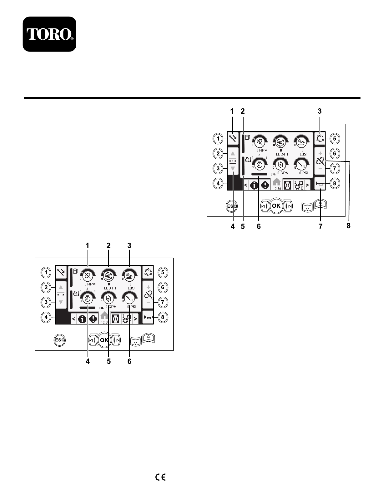
MainInformationScreen
Thisistherstscreenthatappearsaftertheinitial
splashscreen.Tonavigatebetweenscreens,usethe
leftandrightarrows.
Figure1
1.Drillspeed(rpm)4.Enginespeed(rpm)
2.Rotarytorque
3.Thrustforce6.Drilling-uidpressure
5.Drilling-uidowrate
g207712
Figure2
1.Pipefunctions
2.Fuelgauge6.Enginedroop
3.Limitsettingoptions7.Horn
4.Selectpiperow8.Thrustforce,drillspeed
5.Enginetemperaturegauge
(rpm),orrotarytorque
adjustment
Pushbutton1toswitchbetweenthepipefunctions:
pullpipe,pushpipe,neutral.
Pushbutton5toswitchbetweenthrustforce,drill
speed(rpm),androtarytorque.
Usebuttons6and7tosetlimitsforthedrillspeed
(rpm),rotarytorque,andthrustforce.
g207713
©2017—TheT oro®Company
8111L yndaleAvenueSouth
Bloomington,MN55420
Registeratwww.Toro.com.
OriginalInstructions(EN)
PrintedintheUSA
AllRightsReserved
*3413-630*A
Page 2
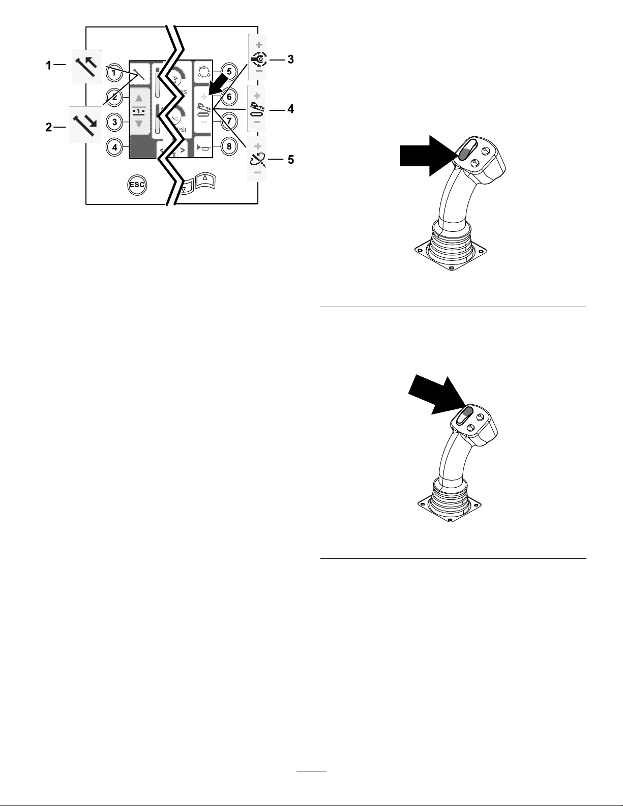
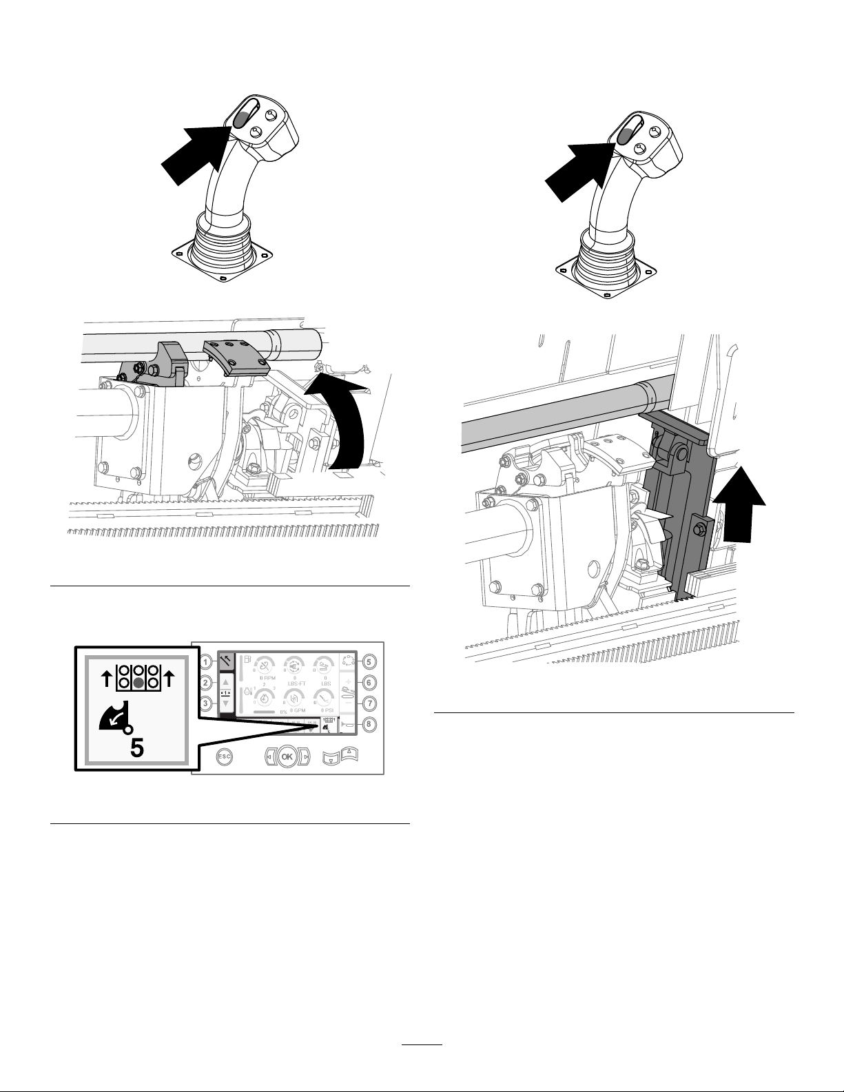
Figure3
PullingPipeinSmartTouchMode
StarttheSmartTouchmodewiththecamassemblyin
thehomeposition(row3ofthepipebox).
Important:Ensurethatyouholdthelowersection
ofthecamrockerswitch,ontheleftjoystick,
completelydownuntiltheactioniscompletein
eachstep(Figure4).
g210057
1.Pullpipe
2.Pushpipe
3.Rotarytorque
4.Thrustforce
5.Drillspeed(rpm)
SmartTouch™HomeScreen
SmartTouchmodeallowstheoperatortoloadand
unloadpipesfromtherodboxwithlessjoystick
operationtoreduceoperatorfatigue.
UsetheCarriageSettingsScreen(page12)toturn
SmartTouchmodeonandoff.
Note:ThePush/PullIconwillhaveagreen
backgroundwhenSmartT ouchmodeisonanda
ribbonwillappearatthebottomofthescreenshowing
asequenceofthesteps.
Important:NeverswitchbetweenPush/Pull
modesduringthechosenoperation.Useneutral
(manual)modetoswitchbetweenPush/Pull;refer
toCarriageSettingsScreen(page12)toturn
SmartTouchmodeoff.
g210060
Figure4
Holdtheuppersectionofthecamrockerswitch,
ontheleftjoystick,completelydownuntilall
actionsarecompletetogotothepreviousstepin
thesequence(Figure5).
g210061
Figure5
1.Pushbutton1toselectthepullpipeoption
(Figure6).
2
Page 3
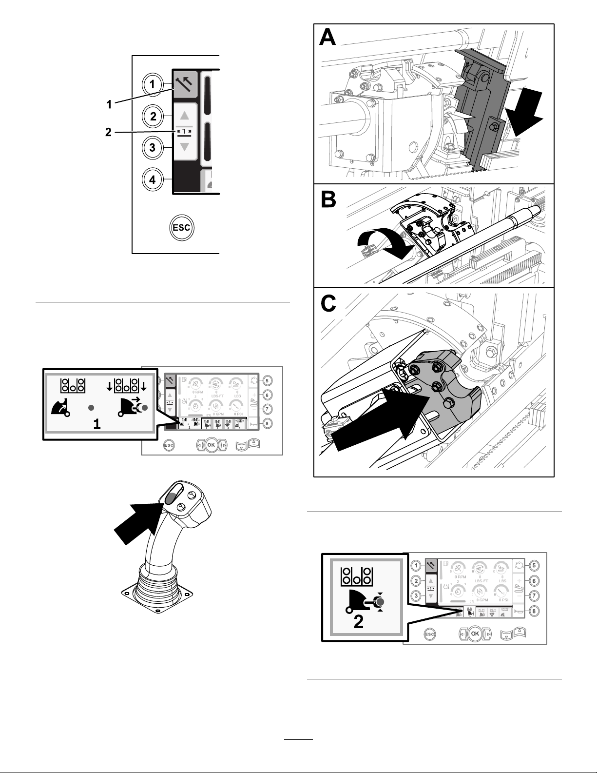
2.Pushbuttons2and3toselecttherowwhere
youwanttoplacethepipe(Figure6).
Figure6
g210062
1.Pullpipe
2.Selectpiperow
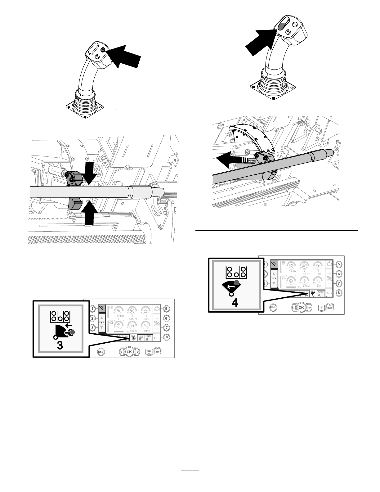
3.Holdthelowersectionoftherockerswitch
(Figure8)untiltheelevatorlowers,thecam
assemblyrotatestowardtheoperatorstation,
andthearmsfullyextend(Figure9).
Figure7
g210518
g210517
Figure9
4.Releasetherockerswitchtoproceedtothenext
stepinthesequence(Figure10).
Figure8
g210462
g210520
Figure10
5.Breakthepipeconnection;refertoRemoving
DrillPipesintheOperator’sManual.
3
Page 4
6.Holdtheupperbuttononthejoysticktogripthe
pipe(Figure11andFigure12)andreleasethe
button.
Figure11
g210462
Figure14
g210533
Figure12
7.Holdthelowersectionoftherockerswitch
(Figure14)untilthearmsfullyretract(Figure
15).
Figure13
g210521
Figure15
8.Releasetherockerswitchtoproceedtothenext
g210519
g210522
stepinthesequence(Figure16).
g210524
Figure16
4
Page 5
9.Holdthelowersectionoftherockerswitch
(Figure17)untilthecamassemblyrotatestothe
selectedrowunderthepipebox(Figure18).
Figure17
11.Holdthelowersectionoftherockerswitch
(Figure20)untiltheelevatorputsthepipeback
inthepipeboxandthecamrotatestothehome
position(Figure21).
g210462
g210462
Figure20
Figure18
10.Releasetherockerswitchtoproceedtothenext
stepinthesequence(Figure19).
Figure19
g210523
g210525
Figure21
12.Releasetherockerswitchtostartthepull-pipe
processagain.
g210526
5
Page 6
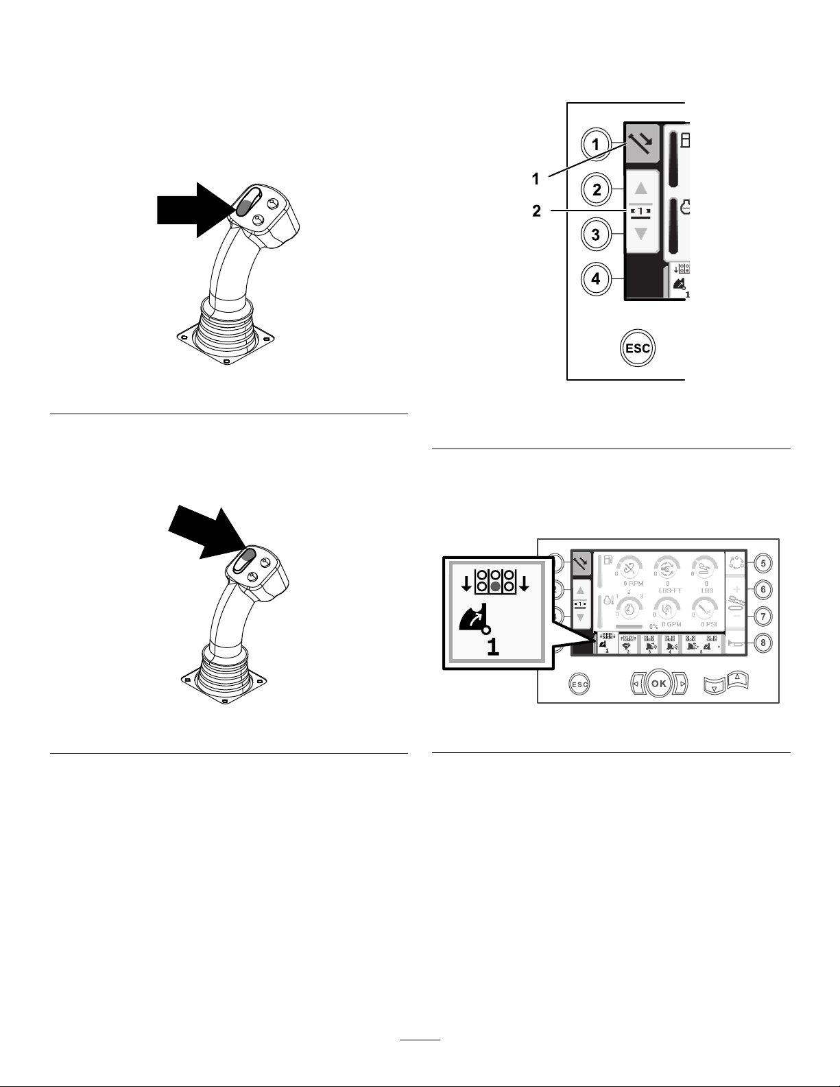
PushingPipeinSmartTouchMode
1.Pushbutton1toselectpushpipe(Figure24).
StarttheSmartTouchmodewiththecamassemblyin
thehomeposition(row3ofthepipebox).
Important:Ensurethatyouholdthelowersection
ofthecamrockerswitch,ontheleftjoystick,
completelydownuntiltheactioniscompletein
eachstep(Figure22).
Figure22
Holdtheuppersectionofthecamrockerswitch,
ontheleftjoystick,completelydownuntilall
actionsarecompletetogotothepreviousstepin
thesequence(Figure23).
2.Pushbuttons2and3toselecttherowwhere
youwanttogetthepipe(Figure24).
g210060
g210063
Figure24
1.Pushpipe
2.Selectpiperow
3.Holdthelowersectionoftherockerswitch
(Figure26)untilthecamassemblyrotatesto
theselectedrowandthepipelowersintothe
opening(Figure27).
Figure23
g210061
g210464
Figure25
6
Page 7

Figure26
5.Holdthelowersectionoftherockerswitch
(Figure29)untilthecamassemblyfullyrotates
forwardtotherackandtheelevatorsliftthe
remainingpipeintothepipebox(Figure30).
g210462
g210462
Figure29
Figure27
4.Releasetherockerswitchtoproceedtothenext
stepinthesequence(Figure28).
Figure28
g210463
g210465
Figure30
6.Releasetherockerswitchtoproceedtothenext
stepinthesequence(Figure31).
g210466
g210467
Figure31
7
Page 8

7.Holdthelowersectionoftherockerswitch
(Figure32)untilthearmsextend(Figure33).
10.Holdthelowerbuttononthejoystick(Figure
35)toreleasethepipe(Figure36)andrelease
thebutton.
Figure32
Figure33
8.Releasetherockerswitchtoproceedtothenext
stepinthesequence(Figure34).
g210462
g210527
Figure35
g210528
g210529
Figure36
Figure34
9.Makethepipeconnection;refertoAddingDrill
PipesintheOperator’sManual.
g210530
8
Page 9

11.Holdthelowersectionoftherockerswitch
(Figure38)untilthearmsretractandthecam
assemblyreturnstothehomeposition(row3)
(Figure39).
12.Releasetherockerswitchtostartthepush-pipe
processagain.Thecamassemblywillgoto
therowpickedinstep2ofPullingPipein
SmartTouchMode(page2).
HoursScreenOptions
MachineHoursScreen
Toaccessthisscreenpushbutton1ontheHours
screen.
Figure37
Figure38
g210532
Thisscreenshowstheoperatinghoursofthe
machine.Machine1cannotbechanged.Machine
2canbereset.
Button5showsthetotalenginehours.
Button6showsenginehoursthatcanberesetby
pushingbutton8.
g210462
g207716
Figure40
Figure39
g210531
9
Page 10

DrillingFluid(Mud)UseScreen
LubricationandMaintenanceScreens
Toaccessthisscreenpushbutton2ontheHours
screen.
Thisscreenshowsthedrillinguid(mud)useofthe
machine.T otaldrillinguid(mud)cannotbechanged.
Dailydrillinguid(mud)canbereset.
Figure41
1.Resetbutton
Toaccessthisscreen,pushbutton3ontheHours
screen.
Thesescreensprovidetheuserwiththedaily
maintenanceschedulesandthe50-hour,250-hour,
500-hour,and1,000-hourincrements.
Toresetthemaintenanceinterval,navigatetothe
MaintenanceandParametersOptionsScreen(page
13),pushthedownarrowtoscrolltothemaintenance
optionsscreen,andenterpin1234546.
Pushbuttons5through8forthecorresponding
serviceintervalandthenpushtheOKbutton3times.
Pushthefollowingbuttonstoattainthesubsequent
maintenanceschedule:
•Button3—10-hour/Dailymaintenanceschedule
(Figure42)
g204519
•Button5—50-hourmaintenanceschedule(Figure
43)
•Button6—250-hourmaintenanceschedule(Figure
44)
•Button7—500-hourmaintenanceschedule(Figure
45)
•Button8—1,000-hourmaintenanceschedule
(Figure46)
Figure42
g034777
10
Page 11

Figure43
Figure44
g034778
g034781
Figure46
g034779
Figure45
g034780
11
Page 12

SettingsScreenOptions
CarriageSettingsScreen
Pushbutton1ontheSettingsscreen.
Usethisscreentochangethecarriagesettings.Push
theupanddownarrowstorotatebetween:pushpipe,
pullpipe,andneutral.
PushPipe:refertoStartingtheFirstPipeandAdding
DrillPipesintheDrillingtheBoresectioninyour
Operator’sManualforfullinstructions.
PullPipe:refertoRemovingDrillPipesintheDrilling
theBoresectioninyourOperator’sManualforfull
instructions.
ControlModeScreen
Pushbutton2ontheSettingsscreen.
Usethisscreentoselectbetweenthe2joystick
controloptions.Pushtheupanddownbuttonsto
switchbetweenModeIandModeII.
Figure47
1.Pullpipe3.Neutral
2.Pushpipe
PushtheOKbuttontoturnSmartTouchmodeonand
off.
g208586
Figure49
g034776
•ModeI—Therightjoystickcontrolsthethrustand
therotationfunctions.Theleftjoystickcontrolsthe
wrenchandpipeloaderfunctions.
•ModeII—Therightjoystickcontrolsthethrustand
thepipeloaderelevatorfunction.Theleftjoystick
controlstherotation,wrench,andpipeloader
functions.
Figure48
g210058
12
Page 13

MaintenanceandParametersOptionsScreen
ScreenSettingsScreen
Pushbutton3ontheSettingsscreen.
Pushtheupanddownarrowstoswitchbetween
MaintenanceandParameters.
TheMaintenancepinnumberis1234546.
TheParameterspinnumberis7326531.
Figure50
Pushbutton6ontheSettingsscreentoswitch
betweenzoomdelay,brightness,anddayornight
mode.Usetheupanddownarrowstoadjustthe
parameters.
TheMainDrillingScreenzoomsintothedrilling
functions.Thesesettingsadjustthedelayonhow
longittakestozoom.
Note:TheSmartT ouchribbonsequencewillbe
hiddenwhenthescreeniszoomedin.
g034783
LanguageandUnitsOptionsScreen
Pushbutton5ontheSettingsscreentoaccessthe
screentoswitchbetweenEnglishandmetricunits.
Usetheupanddownarrowkeystochangethe
languageandunitoptions.
Figure51
g034773
Figure52
ClockSettingsScreen
Pushbutton7ontheSettingsscreentoswitch
betweentheclockoptions.Usetheupanddown
arrowstoadjusttheparameters.
g034767
g034774
Figure53
13
Page 14

I/OScreens
JoystickI/OScreen
Pushbutton1ontheI/OscreentoaccesstheJoystick
I/Oscreen.
Whentherockerswitchontheleftcontrolpanelisin
theDrillposition,theupperlefticonturnsgreenand
youcancheckthejoystickvoltagesaswellasverify
the2–SpeedandExitSideLockout.
WhentherockerswitchisintheSetupposition,the
upperrighticonisgreen.Thesetuppositionallows
youtomovethemachineandpreparefordrilling.
EngineI/OScreen
Toaccessthisscreenpushbutton2ontheI/Oscreen.
Thisscreendisplaysengineinformation.
g204577
Figure55
Figure54
•Therotaryvoltagerangesfrom0.0to8.5Vand
bepresentforeithermake(uppericon)orbreak
(lowericon)astheselectedrotaryjoystickis
moved.
•Thecarriageindicatesarangefrom0.0to10.0
voltsinthejoystickselecteddirectionforthrustor
pullback.
•Thelowerlefticonindicatesthecarriageposition
ofwrench,load,orcarriagebackasthecarriage
movestothemostrearwardpositions.
•Thelowercentericonindicatesifthe2-speed
selectionofthecarriagespeedhasbeenselected.
•ThelowerrighticonindicatesthestatusoftheExit
SideLockout(ESL).Iftheindicatorisblack,the
carriageandrotaryactionsareinhibited.
1.Enginespeed(rpm)5.Airlterindicator
2.Engineoilpressure
g034769
3.Batteryvoltage7.Enginedroop
4.Enginetemperature
6.Hydraulicoillter
8.Waterinfuelindicator
Enginespeed(rpm):displays,instepsof100,the
enginespeed(rpm).
Engineoilpressure:displaystheengineoilpressure
(barorpsi).
Batteryvoltage:displaysthebatteryvoltage.
Iftheengineisoff,thevoltageismeasuredbythe
Torocontroller.
Enginetemperature:displaystheenginecoolant
temperature.Thetemperaturedropsto40°Fwhen
theengineisoff.
Airlter:theairltericonisgreenunlessthelteris
pluggedthentheindicatorisred.
Hydraulicuidlter:thehydraulicuidltericonis
greenunlessthelterispluggedthentheindicator
isred.
Enginedroop:usetheupanddownarrowstoselect
themaximumallowableenginedroopintherangeof
50,75,and80percent.Thedroopvalueisthelowest
pointbelowlow-loadspeed(rpm)(under75percent
load)thattheenginemaydecreasebeforethedrive
totherotaryheadisdecreasedtomaintainthelowest
value.
14
Page 15

CamArmI/OScreen
AuxiliaryI/OScreen
Toaccessthisscreenpushbutton3ontheI/Oscreen.
Usethisscreentoadjustthecamcalibrationoptions.
Pushtheupanddownbuttonstoselecttheload
positionandthepipe-rowposition.
g204520
Figure56
Thevoltageonthebottomindicatesthecamraw
sensorvoltage.Thevoltagesrangefrom1.0to4.0V.
Anyvoltagehigherorlowerindicateseithersensor
failureorincorrectcalibration.
Toaccessthisscreenpushbutton5ontheI/Oscreen.
Alliconschangefromblacktogreenwhenyou
operatetheassociatedfunctions.
Figure57
1.Raise/Lowerelevator5.Armextension/retract
2.Breakoutwrench6.Rotatepipecam
3.Vise
4.Gripper
sensor
7.TJCgrease
g207493
Theothervoltagesarecalibratedvoltages.
Pushbutton3totogglethecalibrationonandoff.
PushtheOKbutton3timesonthedesiredrowto
savethecalibration.
Thebreakoutwrenchiconwillshowarrowsabovethe
icontoindicatewhentherotatingwrenchisopenor
closed.
15
Page 16

ControllerI/OScreen
TravelPendantI/OScreen
Toaccessthisscreenpushbutton6ontheI/Oscreen.
Figure58
1.Seatswitch
2.Exitsidelockout
3.Carriagecrashwarning
4.Mudpumpstatus
5.Mudpumpow
Seatswitch:showsanarrowoutwhennobodyisin
theseatandapersoninwhileyouareintheseat.
Exitsidelockout:changesfromblacktogreenwhen
inoperation.
Carriagecrashwarning:awarningscreen(Figure
59)willappearif:
•thecarriageisinthedrillareaandyoutryto
operatetheloaderarmorpipecamor
•youtrytooperatethecarriagewhentheloader
armorpipecamisnotinthehomeposition.
Toaccessthisscreenpushbutton7ontheI/Oscreen.
Thetravelpendantscreenshowsthevoltageand
positionofthejoysticklocatedonthependant.
g204521
g034772
Figure60
ThereddotisinthecenterofthetargetandtheFNR
(forward,neutral,reverse)andSteervoltageshows
2.5Vpriortoallowingthedrilltomove.Ifthereddot
travelsoutsideoftheoutermostblackring,serviceor
replacethependant.Theindicatorstotherightand
leftofthecircleshowthedirectionofthetracktravel.
Thevoltagesshowarangefrom0to10.0V.
Figure59
Mudpumpstatus:
•Blackicon:mudpumpisoff
•Yellowicon:mudpumpisinstandby
•Greenicon:mudpumpisinon
•Greeniconwith100:mudpumpisinmaxow
Mudpumpow:turnsgreenwhenyouactuatethe
mudowrockerswitch.
g210794
16
Page 17

ErrorsandMachineInformation
MachineInformationScreen
Screens
DrillErrorsScreens
Toaccessthisscreenpushbutton1ontheErrorsand
MachineInformationscreen.
Thisscreendisplaysanydrillerrors.
Pushbuttons5and6topagethroughtheerrors.
Toaccessthisscreenpushbutton3ontheErrorsand
MachineInformationscreen.
Thisscreendisplaysthemachineinformation
includingthemodel,serialnumber,andsoftware
version.
g204578
Figure63
Figure61
EngineErrorsScreen
Toaccessthisscreenpushbutton2ontheErrorsand
MachineInformationscreen.
Thisscreendisplaysanyengineerrors.
Pushbuttons5and6topagethroughtheerrors.
g034787
Figure62
g034788
17
Page 18

Notes:
Page 19

Notes:
Page 20

 Loading...