

Page 1
FormNo.3399-188RevA
Walk-BehindRotaryBroom
ModelNo.23740—SerialNo.316000001andUp
Registeratwww.T oro.com.
OriginalInstructions(EN)
*3399-188*A
Page 2
WARNING
CALIFORNIA
Proposition65Warning
Thisproductcontainsachemicalorchemicals
knowntotheStateofCaliforniatocausecancer,
birthdefects,orreproductiveharm.
Theengineexhaustfromthisproduct
containschemicalsknowntotheStateof
Californiatocausecancer,birthdefects,
orotherreproductiveharm.
Replacementengineowner’smanualsmaybeordered
throughtheenginemanufacturer.
Introduction
Important:ItisaviolationofCaliforniaPublic
ResourceCodeSection4442or4443touseoroperate
theengineonanyforest-covered,brush-covered,or
grass-coveredlandunlesstheengineisequippedwith
asparkarrester,asdenedinSection4442,maintained
ineffectiveworkingorderortheengineisconstructed,
equipped,andmaintainedforthepreventionofre.
Toacquireasparkarresterforyourunit,seeyourEngine
ServiceDealer.
Thismachineisintendedtobeusedbyresidential
homeownersorprofessional,hiredoperators.Itis
designedforremovingsnow,dust,anddirtfrom
pavedsurfaces,suchasdrivewaysandsidewalks,and
othersurfacesfortrafconresidentialorcommercial
properties,aswellasthatchfromgrass.
Readthisinformationcarefullytolearnhowtooperateand
maintainyourmachineproperlyandtoavoidinjuryand
machinedamage.Youareresponsibleforoperatingthe
machineproperlyandsafely .
Figure1
1.Modelandserial-numberlocation
ModelNo.
SerialNo.
Thismanualidentiespotentialhazardsandhassafety
messagesidentiedbythesafety-alertsymbol(Figure2),
whichsignalsahazardthatmaycauseseriousinjuryordeath
ifyoudonotfollowtherecommendedprecautions.
Figure2
1.Safety-alertsymbol
Thismanualuses2wordstohighlightinformation.
Importantcallsattentiontospecialmechanicalinformation
andNoteemphasizesgeneralinformationworthyofspecial
attention.
YoumaycontactTorodirectlyatwww .Toro.comformachine
andaccessoryinformation,helpndingadealer,ortoregister
yourmachine.
Wheneveryouneedservice,genuineT oroparts,oradditional
information,contactanAuthorizedServiceDealerorToro
CustomerServiceandhavethemodelandserialnumbersof
yourmachineready .Figure1identiesthelocationofthe
modelandserialnumbersonthemachine.Writethenumbers
inthespaceprovided.
©2016—TheToro®Company
8111LyndaleAvenueSouth
Bloomington,MN55420
Contactusatwww.Toro.com.
2
PrintedintheUSA
AllRightsReserved
Page 3

Contents
Safety...........................................................................4
Training.................................................................4
Preparation.............................................................4
Operation...............................................................4
ClearingaCloggedBroom........................................5
MaintenanceandStorage..........................................5
SlopeIndicator.......................................................6
SafetyandInstructionalDecals.................................7
ProductOverview..........................................................9
Controls................................................................9
Specications........................................................10
Attachments/Accessories........................................10
Operation....................................................................11
FuelingtheMachine...............................................11
OperatingtheEngine..............................................12
DrivingtheMachine...............................................13
OperatingtheBroom.............................................14
CheckingtheSweepingPath....................................15
AdjustingtheBroomHeight....................................15
AdjustingtheBroomSideAngle...............................16
UsingtheAlternateCasterLocation..........................16
ClearingaCloggedBroom.......................................16
PreventingFreeze-up..............................................17
TransportingtheMachine........................................17
Maintenance.................................................................18
RecommendedMaintenanceSchedule(s)......................18
PreparingforMaintenance.......................................19
Lubrication............................................................19
EngineMaintenance...............................................19
FuelSystemMaintenance........................................22
DriveSystemMaintenance.......................................23
BroomMaintenance...............................................23
MaintainingtheBelts..............................................25
MaintainingtheChassis...........................................27
Storage........................................................................28
PreparingtheMachineforStorage............................28
RemovingtheMachinefromStorage.........................28
Troubleshooting...........................................................29
3
Page 4

Safety
Readandunderstandthecontentsofthismanualbefore
theengineiseverstarted.
Thisisthesafety-alertsymbol.Itisusedtoalertyou
topotentialpersonalinjuryhazards.Obeyallsafety
messagesthatfollowthissymboltoavoidpossibleinjury
ordeath.
Improperlyusingormaintainingthismachinecould
resultininjuryordeath.T oreducethispotential,
complywiththefollowingsafetyinstructions.
Training
•Readtheoperatingandserviceinstructionmanual
carefully.Bethoroughlyfamiliarwiththecontrolsand
theproperuseofthemachine.Knowhowtostopthe
machineanddisengagethecontrolsquickly.
•Donotallowadultstooperatethemachinewithout
properinstruction.
Preparation
CAUTION
Theoperationofanypoweredmachinecanresult
inforeignobjectsbeingthrownintotheeyes.
Alwaysweareyeprotectionduringoperationor
whileperforminganadjustmentorrepair.
CAUTION
Thismachineproducessoundlevelsinexcessof85
dBAattheoperator’searandcancausehearingloss
throughextendedperiodsofexposure.
Wearhearingprotectionwhenoperatingthis
machine.
•Keeptheareaofoperationclearofallpersons,particularly
smallchildren,andpets.
•Thoroughlyinspecttheareawhereyouwillusethe
machineandremovealldoormats,sleds,boards,wires,
andotherforeignobjects.
•Donotoperatethemachinewithoutwearingappropriate
personalprotectiveequipmentsuchashearingprotection,
eyeprotection,dustmask,andgarments.W ear
substantial,slip-resistantfootwear.
•Handlefuelwithcare;itishighlyammable.
–Useanapprovedfuelcontainer.
–Neveraddfueltoarunningorhotengine.
–Fillthefueltankoutdoorswithextremecare.Never
llthefueltankindoors.
–Securethefuelcapafterfuelingandwipeupany
spilledfuel.
•Lettheengineandmachineadjusttooutdoor
temperaturesbeforestartingtoclearsnow.
Operation
•Neverallowchildrentooperatethemachine.
•Donotputhandsorfeetnearorunderrotatingparts.
Keepclearofthedischargeopeningatalltimes.
•Neverdirectdischargeatbystandersorallowanyonein
frontofthemachine.
•Takeallpossibleprecautionswhenleavingthemachine
unattended.Releasethebroom-drivelever,traction-drive
lever,shutofftheengine,andremovethekey.
•Alwaysbesureofyourfooting,andkeeparmholdon
thehandles.Walk;neverrun.
•Neveroperatethemachinewithoutgoodvisibilityor
light.
•Exercisecautiontoavoidslippingorfalling,especially
whenoperatingthemachineinthereversetraveldirection.
•Shutofftheenginewheneveryouleavetheoperating
position,beforeuncloggingthebroomhousing,and
whenmakinganyrepairs,adjustments,orinspections.
•Exerciseextremecautionwhenoperatingonorcrossing
graveldrives,walks,orroads.Stayalertforhidden
hazardsortrafc.
•Neveroperatethemachineathightransportspeedson
slipperysurfaces.Usecareoperatingthemachineinthe
reversetraveldirection.
•Donotclearsnow,dirt,orthatchacrossthefaceof
slopes.Exerciseextremecautionwhenchangingdirection
onslopes.Donotattempttoclearsteepslopes.
•Neveroperatethemachinenearglassenclosures,
automobiles,windowwells,dropoffs,etc.withoutproper
adjustmentofthesnowdischargeangle.Keepchildren
andpetsaway.
•Donotoverloadthemachinecapacitybyattemptingto
clearsnow,dirt,orthatchattoofastofarate.
•Donotoperatetheengineinaconnedspacewhere
dangerouscarbonmonoxideandotherexhaustgasses
cancollect.
•Whencleaning,repairing,orinspecting,ensurethat
therotarybroomandallmovingpartshavestopped.
Disconnectthespark-plugwire,andkeepthewireaway
fromtheplugtopreventaccidentalstarting.
•Disengagethepowertotherotarybroomwhenthe
machineistransportedornotinuse.
•Afterstrikingaforeignobject,shutofftheengine,
disconnectthewirefromthesparkplug,thoroughly
inspectthemachineforanydamage,andrepairthe
damagebeforestartingandoperatingthemachine.
4
Page 5

•Ifthemachineshouldstarttovibrateabnormally,shutoff
theengineandcheckimmediatelyforthecause.Vibration
isgenerallyawarningoftrouble.
•Neveroperatethemachinewithoutproperguards,plates,
orothersafetyprotectivedevicesinplace.
•Useonlyattachmentsandaccessoriesapprovedbythe
manufacturerofthemachine(suchaswheelweights,
counterweights,cabs,etc.).
ClearingaCloggedBroom
WARNING
Therotatingbroomcouldcauseseriousinjury.
Alwaysusecautionwhencleaningthebroom.
Toclearthebroom:
•Movethemachineonlevelground,shutofftheengine,
waitforallmovingpartstostop,anddisconnectthe
spark-plugwire(s).
•Sharpobjectscanbecomeentangledinthebristles.Wear
protectiveglovesandusecautionwhencleaningoutthe
broomofforeignobjects;donotuseyourbarehands.
MaintenanceandStorage
•Neverattempttomakeanyadjustmentswhiletheengine
isrunning(exceptwherespecicallyrecommendedby
themanufacturer).
•Checkallofthefastenersatfrequentintervalsforproper
tightnesstoensurethatthemachineisinsafe,working
condition.
•Neverstorethemachinewithfuelinthefueltankinside
abuildingwhereignitionsourcesarepresent,suchas
hotwaterandspaceheaters,clothingdryers,etc.Allow
theenginetocoolbeforestoringthemachineinany
enclosure.
•AlwaysrefertotheinstructionsintheOperator’sManual
forimportantdetailsifthemachineistobestoredfor
anextendedperiod.
•Maintainorreplacethesafetyandinstructionlabels,as
necessary.
•Whenoperatinginsnowconditions,runthemachinefor
afewminutesafterthrowingsnowtopreventfreezeup
ofthebroomandhousing.
5
Page 6
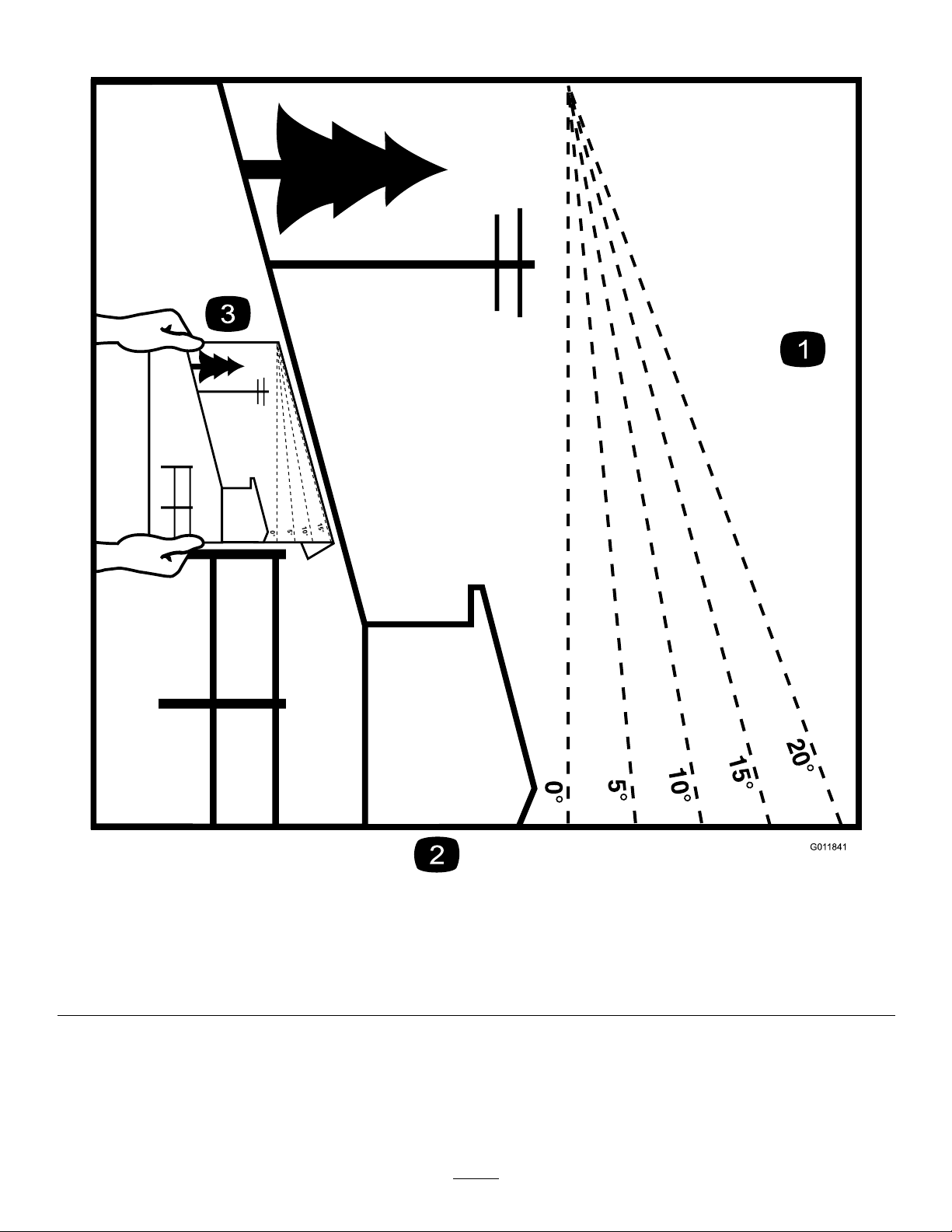
SlopeIndicator
G011841
Figure3
1.Themaximumslopeyoucansafelyoperatethemachineonis10°.Usetheslopeindicatortodeterminethedegreeofslopeof
hillsbeforeoperating.Donotoperatethismachineonaslopegreaterthan10°.Foldalongtheappropriatelinetomatchthe
recommendedslope.
2.Alignthisedgewithaverticalsurface,atree,building,fencepole,etc.
3.Exampleofhowtocompareslopewithfoldededge.
6
Page 7
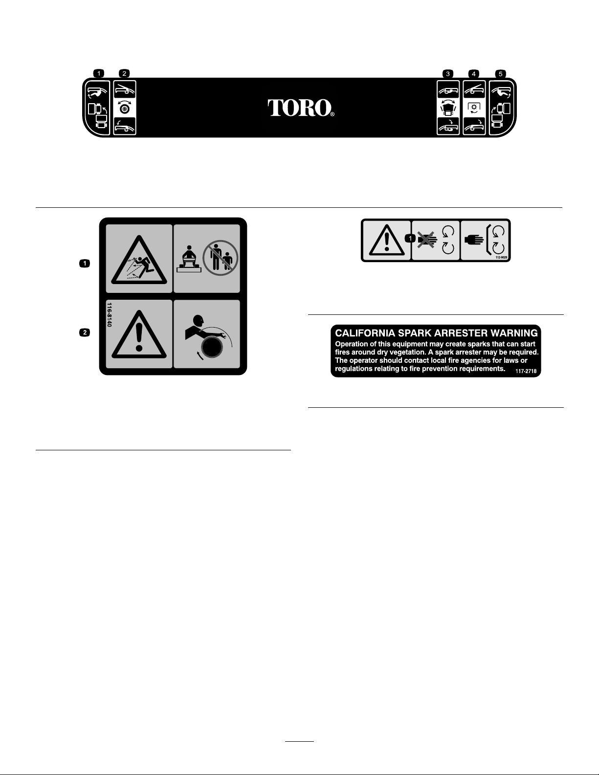
SafetyandInstructionalDecals
Important:Safetyandinstructiondecalsarelocatednearareasofpotentialdanger.Replacedamageddecals.
126–0017
1.Engagetheleft-turnlevertoturnleft.4.EngagethePTOlevertoactivatethePTO.
2.Engagethetraction-controllevertoactivatethetractiondrive.5.Engagetheright-turnlevertoturnright.
3.Engagethebroom-anglelevertoadjustthebroom.
112-9028
1.Warning—stayawayfrommovingparts;keepallguardsin
place.
116-8140
1.Thrownobjecthazard—Donotoperatewhenpeopleand
petsareinthearea.
2.Warning—Entanglementhazard—stayclearoftherotating
broom.
117–2718
7
Page 8
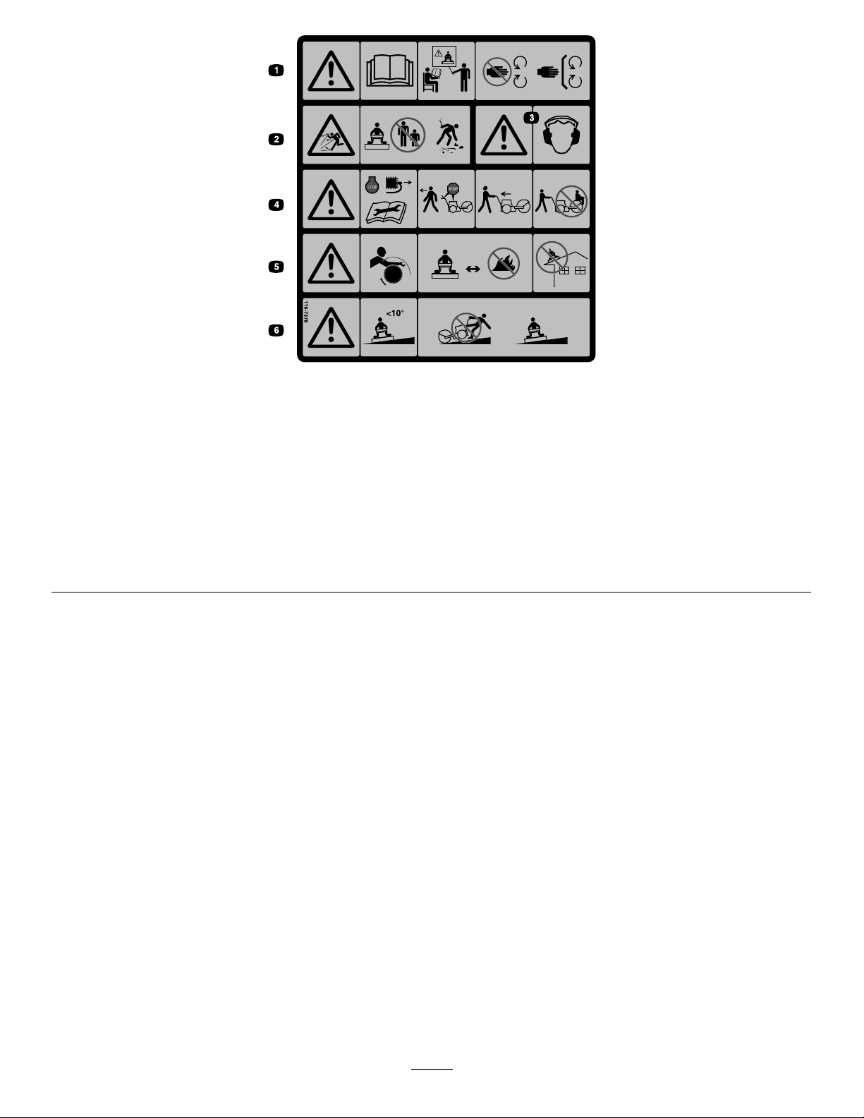
116-7370
1.Warning—ReadtheOperator’sManual.Donotoperatethismachineunlessyouaretrained.Stayawayfrommovingparts;keep
allguardsinplace.
2.Thrownobjecthazard—Donotoperatewhenpeopleandpetsareinthearea;pickupobjectsthatcouldbethrownbybroom.
3.Warning—Wearhearingprotection.
4.Warning—shutofftheengineanddisconnectthesparkplugbeforeadjusting,servicing,orcleaningmachineandattachments.
Beforeleavingtheoperator’sposition,disengagebroom,tractiondrive,andshutoffengine.Lookbehindandtothesidebefore
changingdirections.Donotcarrypassengers.
5.Warning—Entanglementhazard—stayclearoftherotatingbroom.Broombristleswillmeltorburn—keepawayfromextremeheat
orame.Donotoperateonanyrooforotherelevatedsurface.
6.Warning—Donotoperateonslopesgreaterthan10degrees.Useextremecautionwhenoperatingonslopes;operateacross
slopes,notupanddown.
8
Page 9
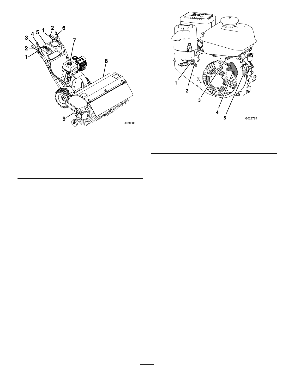
ProductOverview
Figure4
1.Wheel-clutchlever6.Traction-drivelever
2.Handle7.Fuelcap
3.Broom-anglelever8.Broom
4.Broom-drivelever9.Broom-height-adjustment
pin
5.Speed-selectorlever
Controls
Figure5
1.Chokecontrol
2.Fuel-shutoffvalve5.EngineOn/Offswitch
3.Throttlecontrol
4.Engine-recoilhandle
Fuel-ShutoffValve
Usethefuel-shutoffvalvetoshutofftheowoffuelwhen
youwillnotusethemachineforafewdays,parkthemachine
insideabuilding,ortransportthemachinetoandfromthe
jobsite(Figure5).
Determinetheleftandrightsidesofthemachinefromthe
normaloperatingposition.
ChokeControl
Thechokecontrolisthetopleverlocatedontherear,left
sideoftheengineabovethefuel-shutoffvalve(Figure5).
Thechokeisusedtoaidinstartingacoldengine.Movethe
leverlefttotheONpositionforacoldstart.Donotruna
warmenginewiththechokeintheONposition.
Movethelevertothelefttoshutoffthefuel.Movethelever
totherighttoturnonthefuel.
ThrottleControl
Thethrottlecontrolislocatedontherear,rightsideofthe
engineandbelowthefueltank(Figure5).
Thethrottleisusedtocontrolenginespeed.Movingthe
throttlecontroltotheleftincreasestheenginespeed,and
movingitrightdecreasestheenginespeed.
EngineOn/OffSwitch
Locatedontherightsideoftheengine(Figure5).
RotatetheswitchclockwisetotheONpositionbeforestarting
theengine.RotatetheswitchcounterclockwisetotheOFF
positiontoshutofftheengine.
9
Page 10
Wheel-ClutchLevers
Speed-SelectorLever
Thewheel-clutchleversarelocatedbelowtherightandleft
handles.
Thewheelclutchleversallowthedrivetomomentarily
disengageto1orbothwheelswiththetraction-drivelever
squeezed.Thisallowsforeasierturningandmaneuvering
themachine(Figure6).
Note:Squeezingbothwheelclutchleverssimultaneously
disengagesthedrivetobothwheels(free-wheeling).This
enablesyoutomanuallymovethemachinebackwardwithout
stoppingtoshiftitintoareversegear.Italsoallowsyouto
maneuverandtransportthemachinemoreeasilywhenthe
engineisnotrunning.
Thespeed-selectionleverislocatedonthemainconsole
panel(Figure6).
Thespeedselectorhas6forwardand2reversesettings.To
changespeeds,releasethetraction-drivelever,andshiftthe
speed-selectorlevertothedesiredsetting.Theleverlocksina
notchateachspeedsetting.
Broom-AngleLever
Thebroom-angleleverislocatedattherighthandle(Figure6).
Thebroom-anglelevercontrolstheanglelock.Thebroom
anglecanbelockedinto3positions:straightahead,orangled
totheleftorright19°.
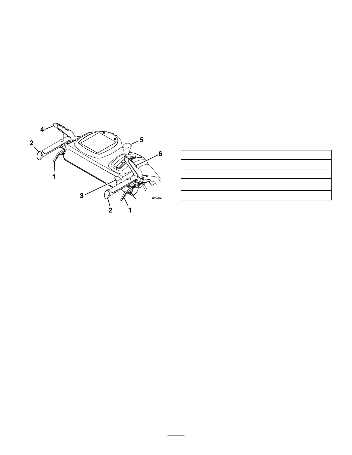
Specications
Width
Length
Height
Weight
Enginespeed(noload)
118cm(46.5inches)
185.5cm(73inches)
105.5cm(41.5inches)
146.5kg(323lb)
Fullspeed:3600±100rpm
Figure6
1.Wheel-clutchlever4.Traction-drivelever
2.Handle
3.Broom-anglelever6.Broom-drivelever
5.Speed-selectorlever
Broom-DriveLever
Thebroom-driveleverislocatedabovetherighthandle
(Figure6).
Toengagethebroom,squeezethelevertothehandle.To
disengagethebroom,releasetherightlever.
Traction-DriveLever
Thetraction-driveleverislocatedabovethelefthandle
(Figure6).
Thetraction-drivelevercontrolstheforwardandreverse
motionofthemachine.Toengagethetractiondrive,squeeze
thelevertothehandle.
Note:Holdingdownthetraction-driveleveragainstthe
handleengagesthetractiondrivetobothwheels.
Attachments/Accessories
AselectionofToroapprovedattachmentsandaccessoriesis
availableforusewiththemachinetoenhanceandexpand
itscapabilities.ContactyourAuthorizedServiceDealeror
Distributororgotowww .Toro.comforalistofallapproved
attachmentsandaccessories.
10
Page 11

Operation
FuelingtheMachine
Fueltankcapacity:4.1L(1.0USgallon)
•Forbestresults,useonlyclean,fresh(lessthan30days
old),unleadedgasolinewithanoctaneratingof87or
higher((R+M)/2ratingmethod).
•Ethanol:Gasolinewithupto10%ethanol(gasohol)
or15%MTBE(methyltertiarybutylether)byvolume
isacceptable.EthanolandMTBEarenotthesame.
Gasolinewith15%ethanol(E15)byvolumeisnot
approvedforuse.Neverusegasolinethatcontains
morethan10%ethanolbyvolume,suchasE15
(contains15%ethanol),E20(contains20%ethanol),or
E85(containsupto85%ethanol).Usingunapproved
gasolinemaycauseperformanceproblemsand/orengine
damagewhichmaynotbecoveredunderwarranty.
•Donotusegasolinecontainingmethanol.
DANGER
Whenfueling,undercertaincircumstances,astatic
chargecandevelop,ignitingthegasoline.Areor
explosionfromgasolinecanburnyouandothers
anddamageproperty.
•Alwaysplacegasolinecontainersontheground
andawayfromyourvehiclebeforelling.
•Donotllgasolinecontainersinsideavehicleor
onatruckortrailerbedbecauseinteriorcarpets
orplastictruckbedlinersmayinsulatethe
containerandslowthelossofanystaticcharge.
•Whenpractical,removegasoline-powered
equipmentfromthetruckortrailerandrefuel
theequipmentwithitswheelsontheground.
•Ifthisisnotpossible,thenrefuelsuch
equipmentonatruckortrailerfromaportable
container,notfromafuel-dispensernozzle.
•Donotstorefueleitherinthefueltankorfuelcontainers
overthewinterunlessyouuseafuelstabilizer.
•Donotaddoiltogasoline.
Important:Donotusefueladditivesotherthanafuel
stabilizer/conditioner.Donotusefuelstabilizerswithan
alcoholbasesuchasethanol,methanol,orisopropanol.
DANGER
Incertainconditions,gasolineisextremely
ammableandhighlyexplosive.Areorexplosion
fromgasolinecanburnyouandothersandcan
damageproperty.
•Fillthefueltankoutdoors,inanopenarea,and
whentheengineiscold.Wipeupanygasoline
thatspills.
•Donotllthefueltankcompletelyfull.Add
gasolinetothefueltankuntilthelevelis6to13
mm(1/4to1/2inch)belowthebottomofthe
llerneck.Thisemptyspaceinthetankallows
thegasolinetoexpand.
•Neversmokewhenhandlinggasoline,andstay
awayfromanopenameorwhereasparkmay
ignitethegasolinefumes.
•Storegasolineinanapprovedfuelcontainerand
keepitoutofthereachofchildren.
•Neverbuymorethana30-daysupplyof
gasoline.
•Ifyoumustuseafuel-dispensernozzle,keepthe
nozzleincontactwiththerimofthefueltank
orcontaineropeningatalltimesuntilfuelingis
complete.
AddingFueltotheFuelTank
1.Cleanaroundthefuel-tankcap(Figure7).
Figure7
1.Fillerneck2.Fuel-tankcap
2.Removethecapfromthefueltank(Figure7).
3.Fillthefueltankwithunleadedgasolinetowithin6to
13mm(1/4to1/2inch)fromthetopofthetank.Do
notllintothellerneck.
Important:Donotllthetankmorethan6mm
(1/4inch)fromthetopofthetanktoallowthe
gasolineroomtoexpand.
4.Installthefuel-tankcapandwipeupanyspilled
gasoline(Figure7).
11
Page 12

OperatingtheEngine
PositioningtheAir-CleanerCoverfor
ColdorWarmAirTemperature
Important:Runningtheenginewiththeair-cleaner
coverpositionedforcold-weatheroperationinnormal
conditionscandamagetheengine.
Theair-cleanercoverhas2positions:thecoldornormal,
ambientairpositions:
Adjusttheair-cleanercoverasfollows:
•Whenoperatinginacoldambientaircondition(coldair
temperatureandhumidity),positiontheair-cleanercover
withsnowakedecalfacingout(Figure8).
Note:Usethispositionifyourmachineexhibits
carburetoricing.Symptomsincludetheengineruns
roughatidleorlowspeed,anditdischargesblackor
whitesmokeintheexhaust.
•Whenoperatinginanormalambientaircondition,
positiontheair-cleanercoverwithsundecalfacingout
(Figure8).
Note:Usethispositionifyourmachineisnotexhibiting
carburetoricing.
OpeningtheFuel-ShutoffValve
Movethefuel-shutoffvalvelocatedbelowthechoke,tothe
righttoturnonfuel(Figure9).
Figure9
1.FUELONposition3.Choke
2.Fuel-shutoffvalve
StartingtheEngine
1.Ontherightsideoftheengine,rotatetheengine
On/OffswitchclockwisetotheONposition(Figure
10).
1.Normalambientair
position
Figure8
2.Coldambientairposition
Figure10
1.Engine-recoilhandle
2.Throttle
3.Engineswitch(OFF
position)
4.Engineswitch(ON
position)
2.Ontherear,leftsideoftheengine,movethechoke
levertotheONposition.Onawarmengine,leavethe
chokeleverintheOFFposition(Figure9).
12
Page 13

3.PlacethethrottlemidwaybetweentheSLOWandFAST
positionslocatedonrear,rightsideoftheengine
(Figure10).
4.Slowlypulltheengine-recoilhandleuntilyoufeel
resistanceandthenstop(Figure10).
Note:Allowtherecoilhandletoreturnandthen
sharplypullitstraightout.
Note:Allowtheropetoreturnslowly.
5.Allowtheenginetowarmupforseveralminutes,then
movethechokelevertowardtheOFFposition(Figure
9).
ShuttingoftheEngine
1.Releasethebroom-driveleverandthetraction-drive
lever.
2.PlacethethrottlemidwaybetweentheSLOWandFAST
positions(Figure10).
3.Allowtheenginetorunforaminimumof15seconds,
thenturntheengineOn/OffswitchtotheOFF
positiontoshutofftheengine(Figure10).
4.Waitforallmovingpartstostopbeforeleavingthe
operatingposition.
5.Usethefuel-shutoffvalvetoshutofftheowoffuel
whenyouwillnotusethemachineforafewdays,park
themachineinsideabuilding,ortransportthemachine
toandfromthejobsite(Figure9).
Figure11
Note:Ifthegroundspeedistoofast,debrisorsnow
willpileupinfrontofthebroomcausingthebroom
tobulldozeinsteadofsweep.Thiscandamagethe
bristlesandthedriveline.
2.Slowlysqueezethelefttraction-drivelevertothe
handle(Figure12).
Note:Holdingdownthetraction-driveleveragainst
thehandleengagesthetractiondrivetobothwheels.
Figure12
DrivingtheMachine
CAUTION
Ifthetractiondriveisnotproperlyadjusted,the
machinemaymoveinthedirectionoppositeof
whatyouintended,causinginjuryand/orproperty
damage.
Carefullycheckthetractiondriveandadjustit
properly,ifnecessary.
Important:Ifthemachinemoveswhenthetraction
leverisinthereleasedposition,checkthetractioncable;
refertoCheckingtheTractionCable(page23)and
AdjustingtheTractionCable(page23)orcontactyour
authorizedT orodealer.
DrivingForward
1.Placethespeedselectorlevertothedesiredforward
position,makingsurethatitlocksinthenotch(Figure
11).
3.Tostopthetractiondrive,releasethetraction-drive
lever.
4.Tomoveforward,engagethetractiondriveandslowly
squeezethelefthandtractionlevertothehandle
(Figure13).
Note:Momentarilysqueezingandreleasingtheleftor
rightwheel-clutchleverallowsforsteeringadjustments
tokeepthemachinegoinginastraightline,especially
indeepsnow.
Note:Toturnright,liftupontherightwheel-clutch
leverandsqueezeittowardthehandle.Thisdisengages
thedrivetotherightwheel,whiletheleftwheel
continuesdriving,andthemachineturnstotheright.
Figure13
13
Page 14

Note:Similarly,squeezingtheleftwheel-clutchlever
turnsthemachinetotheleft.
OperatingtheBroom
Note:Whenyoucompletetheturn,releasethe
wheel-clutchlever.Thedriveengagesbothwheels
(Figure14).
Figure14
5.Tostopthetractiondrive,releasethetraction-drive
lever.
DrivingtheMachineRearward
1.Placethespeed-selectorleverintothedesired
reverse-speedrange,makingsurethatthespeed
selectorlocksinthenotch.
2.Tomoverearward,engagethetractiondriveandslowly
squeezethelefttractionlevertothehandle.
Note:Momentarilysqueezingandreleasingtheleftor
rightwheel-clutchleverallowsforsteeringadjustments
tokeepthemachinegoinginastraightline.
Note:Toturnright,squeezetherightwheel-clutch
levertowardthehandle.Thisdisengagesthedriveto
therightwheelwhiletheleftwheelcontinuesdriving,
andthemachineturnstotheright.
Note:Similarly,squeezingtheleftwheel-clutchlever
turnsthemachinetotheleft.
Note:Squeezingbothwheel-clutchleverssimultaneously
disengagesthedrivetobothwheels.Thisenablesyouto
movethemachinerearwardwithoutstoppingtoshiftitintoa
reversegear.Italsoallowsyoutomaneuverandtransportthe
machinemoreeasilywhentheengineisnotrunning.
DANGER
Whenthemachineisinoperation,contactwith
rotatingormovingpartswillseverelyinjurehands
andfeet.
•Beforeadjusting,cleaning,inspecting,
troubleshooting,orrepairingthemachine,shut
offtheengineandwaitforallmovingpartsto
stop.Disconnectthewire(s)fromthespark
plug(s)andkeepitawayfromtheplugtoprevent
someonefromaccidentallystartingtheengine.
•Staybehindthehandlesandawayfromthe
broomwhileoperatingthemachine.
•Keepface,hands,feet,andanyotherpartof
yourbodyorclothingawayfromconcealed,
moving,orrotatingparts.
WARNING
Contactwitharotatingbroomcanresultin
seriouspersonalinjuryordeathtotheoperatoror
bystanders.
•Toremoveanobstructionfromthebroom;refer
toClearingaCloggedBroom(page16).
•Donotoperatethemachineifthebroomdrive
leverisnotfunctioningproperly.Contactyour
authorizedT orodealer.
WARNING
Therotatingbroomcanthrowstonesandother
foreignobjects,causingseriouspersonalinjuryto
theoperatorortobystanders.
•Keeptheworkingareaclearandfreeofall
objectsthatthebroomcouldpickupandthrow.
•Keepallchildrenandpetsawayfromthearea
ofoperation.
CAUTION
Whenthebroomisengaged,itmaydrivetheunit
inthereversedirection.Ifthebroomheightis
adjustedtoolow,themachinemaymovemore
forcefullyinthereversedirection,causinginjury
and/orpropertydamage.
Carefullycheckthebroomheightandadjustit
properlyorcontactyourauthorizedT orodealer.
1.SettheenginethrottletotheFASTposition.
14
Page 15

2.Placethespeedselectorleverintothedesiredposition
andslowlysqueezethelefthandtractiondrivelever.
Important:Makesurethatthetractiondriveis
engagedbeforeoperatingthebroom;otherwise,
thebroommaydrivetheunitinthereverse
direction.
3.Toengagethebroom,slowlysqueezetherightbroom
levertothehandle(Figure15).
Figure16
Figure15
•Iftheengineslowsdownunderaloadorthe
wheelsslip,shiftthemachineintoalowergear.
•Ifthefrontofthemachineridesup,shiftthe
machineintoalowergear.Ifthefrontcontinues
torideup,liftuponthehandles.
4.Tostopthebroom,releasetherightlever.
CheckingtheSweepingPath
Abroomsweepswiththetipsofitsbristles.Whenyouapply
toomuchdownwardpressure,thebroomnolongerusesits
tips;thebroomisnowworkingwiththesidesofthebristles.
Thislimitstheickingactionofthebristlesandsweeping
effectiveness,decreasingtheservicelifeofthebroom.
1.Drivetoaat,dustyareaandstopthemachine.
2.Withtheenginerunningmovethethrottlemidway
betweenSLOWandFAST.
3.Engagethebroomandallowthebroomtosweepfor
approximately30seconds.
1.51to102mm(2to4
inches)maximumwidth
2.Lengthofbroom
3.Sweptarea
8.Adjustthebroomheight,ifnecessary.
AdjustingtheBroomHeight
1.Drivetoaat,dustyareaandstopthemachine.
2.Disengagethebroomandshutofftheengine.
3.Waitforallmovingpartstostopbeforeleavingthe
operatingposition.
4.ShutofftheengineOn/OffswitchtotheOFFposition.
5.Toadjustthebroomheight,removeandretainthepin
fromtheadjustersleeveandwheeltubeofthecaster
(Figure17).
4.Disengagethebroomandshutofftheengine.
5.Waitforallmovingpartstostopbeforeleavingthe
operatingposition.
6.ShutofftheengineOn/OffswitchtotheOFFposition.
7.Makesurethattheareasweptequalsthelengthofthe
broomandamaximumwidthof51to102mm(2to
4inches).
1.Caster-wheeltube
2.Positionstoachieve3mm
(1/8inch)increments
15
Figure17
3.Pin
4.Adjustersleeve
Page 16

6.Raiseorlowerthecasterwheeltubetoachievethe
sweepareaasstatedinCheckingtheSweepingPath
(page15).
UsingtheAlternateCaster Location
Note:Selectanyholecombinationthatisinalignment
toplaceandlatchtheretainingpin;matchthesame
positionontheotherside.
7.Fornetuningadjustments,slidetheadjustersleeve
1pinholeupordownonthecasterwheeltubeto
adjustthebroomheightin3mm(1/8inch)increments
(Figure17).Repeatsteps5through7fortheother
casterwheel.
•Toraisethebroomin3mm(1/8inch)increments,
slightlyraisetheadjustersleeveandinsertthepin
intothenextpinholebelowthecurrentholeused.
•Tolowerthebroomin3mm(1/8inch)increments,
slightlylowertheadjustersleeveandinsertthepin
intothenextpinholeabovethecurrentholeused.
8.Whenyouattainthedesiredheight,securethepinon
eachcasterwheel,andcheckthesweepingarea.
AdjustingtheBroomSide Angle
1.Disengagethebroomandshutofftheengine.
Whenworkinginsnow ,mountthecastersbehindthebroom
bristles(Figure18).
Figure18
1.Hardware
2.Caster
ClearingaCloggedBroom
2.Waitforallmovingpartstostop.
3.Pushtheleverdownwiththethumbofyourrighthand
(Figure6).
4.Squeezetheleftwheel-clutchlevertothehandleand
pushthebroomhousingtothedesiredangle.
Note:Thebroomcanrotate19°totherightorleft,
orstraightahead.
5.Oncethebroomispositioned,releasethebroom-angle
lever.
6.Releasetheleftwheel-clutchleverandmakesurethat
thebroomislockedintoplace.
WARNING
Therotatingbroomcouldcauseseriousinjury.
Shutoffthemachineandallowallrotatingpartsto
stopbeforecleaningthebroom.
•Ifthebroombecomesclogged,stayintheoperating
positionandreleasethelefttraction-drivelever.While
engagingthebroom,pushdownonthehandlestoraise
thefrontofthemachineafewcentimeters(inches)offthe
pavement.Thenliftthehandlesquicklytobumpthefront
ofthemachineonthepavement.Repeatifnecessary.
•Ifyoucannotunclogthebroombybumpingthefront
ofthemachine:
–Parkthemachineonlevelground.Shutoffthe
engine,waitforallmovingpartstostop,and
disconnectthespark-plugwire.
–Wearprotectiveglovesandusecautionwhencleaning
outthebroomofforeignobjects;donotuseyour
barehands.
16
Page 17

PreventingFreeze-up
•Insnowyandcoldconditions,somecontrolsandmoving
partsmayfreeze.Donotuseexcessiveforcewhen
tryingtooperatefrozencontrols.Ifyouhavedifculty
operatinganycontrolorpart,starttheengineandletit
runforafewminutes.
•Afterusingthemachine,lettheenginerunforafew
minutestopreventmovingpartsfromfreezing.Engage
thebroomtoclearanyremainingsnowfrominsidethe
housing.Shutofftheengineandwaitforallmovingparts
tostop,anddisconnectthespark-plugwire.Removeall
ice,snow,orotherdebrisfromthemachine.
•Connectthespark-plugwire.Withtheengineswitchin
theOFFposition,pulltherecoil-starterhandleseveral
timestopreventtherecoilstarterfromfreezingup.
TransportingtheMachine
WARNING
Usingrampsthatarenotstrongenoughorproperly
supportedtoloadthemachineontothetransport
vehiclecouldbedangerous.Therampscould
collapse,causingthemachinetofall,whichcould
causeinjury.
•Useproperrampsthataresecuredtothetruck
ortrailer.
•Keepfeetandlegsoutfromunderthemachine
whenloadingandunloading.
PreparingtoTransporttheMachine
Performthefollowingbeforetransportingthemachine:
•Ensurethatthefuel-shutoffvalveisclosed.
•Placethemachineineitheraforwardorreversegear,
thenblockthewheels.
•Securelyfastenthemachinetothetrailerwithstraps,
chains,cables,orropes.
•Ensurethatthetrailerhasallthenecessarylightingand
markingasrequiredbylaw.
17
Page 18

Maintenance
Note:Determinetheleftandrightsidesofthemachinefromthenormaloperatingposition.
RecommendedMaintenanceSchedule(s)
MaintenanceService
Interval
Aftertherst2hours
Aftertherst5hours
Beforeeachuseordaily
Every50hours
Every100hours
Every200hours
Every300hours
Yearly
Yearlyorbeforestorage
MaintenanceProcedure
•Checkthetractioncable.
•Checkthebroomcable.
•Changetheengineoil.
•Checktheengine-oillevel.
•Checkthebroom-shaftshearpin.
•Checkforloosehardware.
•Cleanthefoampre-cleaner(morefrequentlyindustyconditions).
•Checkthetirepressure.
•Checktheconditionofthebelts.
•Lubricatethebroom-angle-lockpin.
•Changetheengineoil(morefrequentlyinsevereconditions).
•Checkthesparkplug.
•Replacethefoampre-cleaner.
•Replacethepaperairlter(morefrequentlyindustyconditions).
•Lubricatethehexshaft.
•Checkthetractioncable.
•Checkthebroomcable.
•Checktheairpressureinthedrivetiresandinatethemto116to137kPa(17
to20psi).
•Drainthegasolineandruntheenginetodryoutthefueltankandthecarburetorat
theendoftheseason.
•Haveanauthorizedservicedealerinspectandreplacethetraction-drivebelt,if
necessary.
Important:Youcanndmoreinformationaboutmaintainingandservicingyourmachineatwww.Toro.com.
Important:Refertoyourengineoperator'smanualforadditionalmaintenanceprocedures.Forengineadjustments,
repairs,orwarrantyservicenotcoveredinthismanual,contacttheauthorizedengineservicedealer.
18
Page 19

PreparingforMaintenance
1.Movethemachinetoalevelsurface.
2.Shutofftheengineandallowittocool.
3.Disconnectthespark-plugwirefromthesparkplug
andkeepthewireawayfromtheplug,toprevent
accidentalstarting(Figure19).
2.Removethebeltcoverandtheengineshield.
3.Movethespeed-selectorlevertotheR2position.
4.Dipalong,clean,small-tippedpaintbrushin
automotiveengineoilandlightlylubricatethehexshaft
(Figure21).
Important:Donotgetoilontherubberwheelor
thealuminumfriction-driveplateasthetraction
drivewillslip(Figure21).
Note:Rockthemachineforwardandrearwardto
rotatethehexshaft.
Figure19
1.Spark-plugwire
Lubrication
LubricatingtheBroom-Angle-LockPin
andtheHexShaft
ServiceInterval:Every100hours
Yearly
1.Lubricatethebroom-angle-lockpinttingwithNo.2
lithiumgrease(Figure20).
Figure21
1.Aluminumfriction-drive
plate
5.Movethespeedselectorlevertoposition6.
6.Lubricatetheotherendofthehexshaft.
7.Movethespeedselectorleverforwardandrearward
afewtimes.
8.Installthebeltcoverandtheengineshield.
2.Hexshaft
EngineMaintenance
ServicingtheAirCleaner
ServiceInterval:Every50hours—Cleanthefoam
pre-cleaner(morefrequentlyindusty
conditions).
Every200hours—Replacethefoampre-cleaner.
Every300hours—Replacethepaperairlter(more
frequentlyindustyconditions).
1.Broom-angle-lockpin
Figure20
Important:Donotoperatetheenginewithouttheair
lterassembly;extremeenginedamagemayoccur.
1.Releasethelatchesonthecoverfortheaircleaner.
2.Removethecoverandcleanitthoroughly(Figure22).
Note:Becarefultopreventdirtanddebrisfrom
fallingintothebase.
19
Page 20

Figure23
G023796
1.Alignment-arrowdecal(normalambientairpositionshown)
9.Securetheair-ltercovertothebasewiththelatches.
Figure22
1.Air-lterbase4.Cover
2.Paperairlter
3.Foampre-cleaner
5.Latchontheair-cleaner
cover(2)
3.Removethefoampre-cleaner,washitwithamild
detergentandwater,andthenblotitdry(Figure22).
4.Removeandinspectthepaperairlter(Figure22);
discarditifitisexcessivelydirty.
Important:Donottrytocleanapaperlter.
5.Wipedirtawayfromthebaseandthecoverwitha
moistrag.
Note:Becarefultopreventdirtanddebrisfrom
enteringtheairductleadingtothecarburetor.
6.Installthefoampre-cleanerontothepaperairlter
(Figure22).
Note:Useanewpaperairlterifyoudiscardedthe
oldone.
7.Installtheairlterassemblytotheair-lterbase
(Figure22).
CheckingtheEngine-OilLevel
ServiceInterval:Beforeeachuseordaily
EngineOilType:Toro4-CyclePremiumEngineOil
Usehigh-qualitydetergentoils(includingsynthetic)ofAPI
(AmericanPetroleumInstitute)serviceclassSJorhigher.
Selecttheviscositybasedontheairtemperatureattimeof
operationasshowninthetablebelow .
Figure24
Checktheoillevelwhentheengineiscold.
1.Cleantheareaaroundthedipstick.
2.Removethedipstickandreadtheoillevel(Figure25).
8.Alignthearrowdecalontheair-cleanercoverandthe
arrowdecalonthebase(Figure23).
20
Page 21

Figure25
1.Fillerneck2.Dipstick
ChangingtheEngineOil
ServiceInterval:Aftertherst5hours
Every100hours(morefrequentlyinsevere
conditions).
Oilcapacity:0.60L(0.63qt)
Note:Draintheengineoilwhiletheengineiswarm.
1.Placeapanunderdrainttingandremovetheoil-drain
cap(Figure26).
3.Removethedipstickandwipeofftheoilwithaclean
rag.
4.Insertthedipstickintothellerneck,restitontheoil
llerneck,andturnitcounterclockwiseuntilthecap
dropsdowntolowestpointofthethreadleads.
Note:Donotthreadthecapontothetube.
5.Removedipstickandcheckoillevel.
Note:Donotoperatetheenginewiththeoillevel
belowtheAddmarkorabovetheFullmarkonthe
dipstick.
Note:Theoillevelshouldbeattopoftheindicator
onthedipstick(Figure25).
•Iftheoillevelislow ,performthefollowing:
A.Pourthespeciedoilintothellerneck
(Figure25).
Note:Donotoverlltheenginewithoil.
B.Repeatsteps3through5.
•Iftheoillevelishigh,preformthefollowing:
A.Removethecapfromthedraintting.
B.Draintheoiluntiltheoillevelisatthetopof
theindicatorondipstick;refertosteps1of
ChangingtheEngineOil(page21).
C.Installthecapontothedraintting;referto
step2ofChangingtheEngineOil(page21).
6.Insertthedipstickintothellerneckandtightenthe
dipstickbyhand.
Figure26
1.Draintting
2.Cap
3.Drainpan
2.Allowtheoiltodrainandtheninstalltheoil-draincap.
3.Cleanaroundthellerneckandremovethedipstick.
4.Filltothespeciedcapacitywiththespeciedoiland
replacethedipstick;refertoCheckingtheEngine-Oil
Level(page20).
Note:Donotoverlltheenginewithoil.
5.Wipeupanyspilledoil.
6.Starttheengineandcheckforleaks.
7.Shutofftheengineandchecktheoillevel;referto
CheckingtheEngine-OilLevel(page20).
21
Page 22

CheckingtheSparkPlug
G019300
1 2
4
3
ServiceInterval:Every100hours
Sparkplugtype:Champion®RC12YC,Kohler®12132
02-S,orKoher2513214-S(RFIcompliant)
Spark-pluggap:0.76mm(0.030inch)
1.Disconnectthespark-plugwirefromtheterminalof
thesparkplug(Figure19).
2.Cleantheareaaroundthebaseofthesparkplug.
3.Removethesparkplugfromthecylinderheadby
rotatingtheplugcounterclockwise.
4.Examinetheplugforwearanddamage(Figure27).
Important:Replaceacracked,fouled,ordirty
sparkplug.Donotcleantheelectrodes,because
gritenteringthecylindercandamagetheengine.
Figure28
1.Bowl-retainingscrew2.Drainbolt
Figure27
1.Groundelectrode
2.Centerelectrode4.Spark-pluggap0.76mm
3.Insulator
(0.030inch)
5.Checkthespark-pluggapwithawiregauge(Figure27).
Note:Ifnecessary,adjustthegapto0.76mm(0.030
inch)bycarefullybendingthegroundelectrode.
6.Installthesparkplugbythreadingitintothecylinder
headandtorquingtheplugto20N∙m(14lb-ft).
7.Connectthespark-plugwiretotheterminalofthe
sparkplug.
FuelSystemMaintenance
DrainingtheFuelSystem
2.Aligntheequipmentthatyouwillusetocollectthefuel
beneaththedrainscrew .
3.Removethedrainscrewfromthecarburetorandallow
thefueltodrainfromthefueltankandthecarburetor.
Note:Donotremovethebowl-retainingscrewfrom
carburetor.
1.Locatethedrainboltthatisinthesideportofthe
carburetorbowl(Figure28).
1.Sideportofthecarburetor
bowl
Figure29
2.Drainbolt
4.Installthedrainboltintothesideportofthecarburetor.
22
Page 23

DriveSystemMaintenance
3
g019016
CheckingtheTirePressure
ServiceInterval:Every50hours
1.Shutofftheengine,waitforallmovingpartstostop,
andleaveengineswitchintheOFFposition.
2.Checkthetirepressureinthedrivetires.
3.Inatethedrivetiresto117to138kPa(17to20psi).
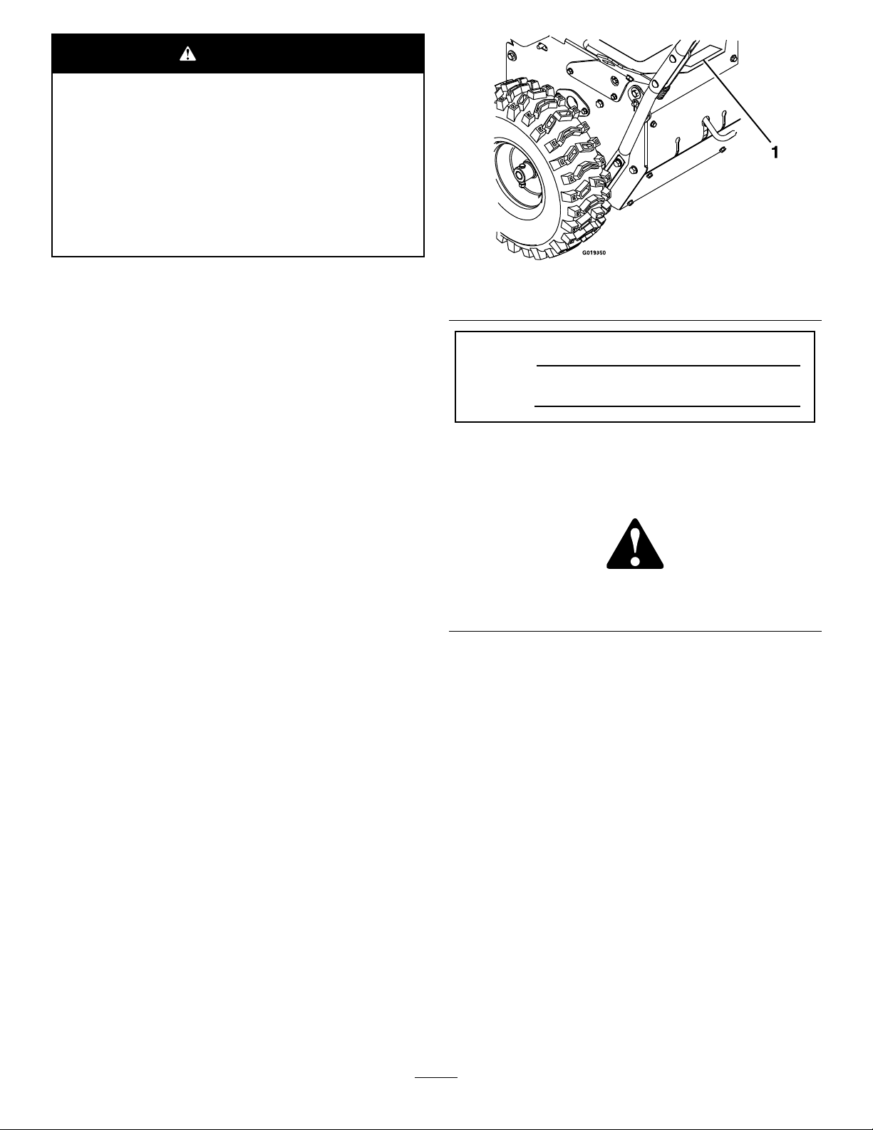
CheckingtheTractionCable
ServiceInterval:Aftertherst2hours
Yearly
2.Loosenortightentheturnbuckletoadjustthepinuntil
itisthepropergapfromthefrontedgeoftheslot
(Figure31).
3.Tightenthejamnut(Figure31).
1.Shutofftheengine,waitforallmovingpartstostop,
anddisconnectthespark-plugwire.
2.Withthetractionleverdisengaged,checkthepinin
theelongatedslotintheleftsideofthemachineabove
thetire(Figure30).
Note:Thereshouldbeagapof6mm(1/4inch)
fromthefrontoftheslottothefrontedgeofthepin
(Figure30).
Note:Ifadjustmentisnecessary,referto(Figure30).
Figure30
1.Pin
2.6mm(1/4inch)
Figure31
1.Jamnut3.Tractioncable
2.Turnbuckle
AdjustingtheWheel-ClutchCable
1.Squeezetheleverfully,thencheckthegapbetweenthe
bottomofthehandleandthewheel-clutchleverend
(Figure32).
Figure32
Note:Thegapshouldbeapproximatelythethickness
ofapencil(6mmor1/4inch).Ifitisgreater,loosen
thecableclampnut,slidethecablejacketupslightly,
tightenthecableclampnut,andcheckthegapagain.
AdjustingtheTractionCable
Ifthemachinedoesnotdriveintheforwardorreversespeeds
oritdriveswhenyoureleasethetractionlever,adjustthe
tractioncable.
Withthetractionleverdisengaged,checkthepininthe
elongatedslotintheleftsideofthemachineabovethetire.
Thereshouldbeagapof6mm(1/4inch)fromthefront
oftheslottothefrontedgeofthepin;refertoChecking
theTractionCable(page23).
Ifthelefthandtractioncableisnotproperlyadjusted,do
thefollowingsteps:
1.Loosenthejamnut(Figure31).
2.Repeatfortheothercable(Figure32).
BroomMaintenance
CheckingtheBroom-ShaftShearPin
ServiceInterval:Beforeeachuseordaily
1.Movethemachinetoalevelsurface.
2.Shutofftheengine,waitforallmovingpartstostop,
anddisconnectthespark-plugwire.
3.Checktheshearpinlocatedonthebroomshafton
eithersideofthegearbox.
23
Page 24

Figure33
4.Supportthesplineshaftoneithersideofthegearbox.
5.Standthebroomcoreassemblyonendsothatthe
removableendretainerplatefacesupward(Figure35).
1.Nut
2.Shearpin
4.Iftheshearpinisdamaged,removethepin,replaceit,
andsecuretheitwithanut.
ReplacingWornorDamagedBroom
Segments
ServiceInterval:Asrequired.
1.Raisethebroombysettingthecasterpositions.
2.Onbothsidesoftheunit,removeandretainthe
carriagebolts,washers,andlocknutsthatsecurethe
endbearingstothebroomsupport.
Figure35
1.Hardware
2.End-retainerplate
3.Broomsegment
4.Supportshaft
5.Alignmentngers
6.Removeandretainthehardwarefromtheend-retainer
plate(Figure35).
7.Removethedamagedbroomsegment(s).
8.Installthenewsegment(s)bystaggeringthemetalring
alignmentngersasshowninFigure35.
Important:Y oumaydamagethebroomassembly
ifyoudonotproperlyinstallthebroomsegments.
9.Installthebroomassemblyontotheunit.
Important:Makesurethatthebearingsetscrews
aretightenedbeforeoperatingthebroom.
Figure34
1.Broomsupport4.Endbearing
2.Locknut
3.Washer
5.Carriagebolt
3.Manuallypullthepowerunitrearwardtoremovethe
broomassemblyfromtheunit.
CheckingtheBroomCable
ServiceInterval:Aftertherst2hours
Yearly
1.Shutofftheengine,waitforallmovingpartstostop,
anddisconnectthespark-plugwire.
2.Removethebeltcoverandengineshield.
3.Withthebroomleverdisengaged,ensurethegap
betweenthebroom-clutchassemblyandthetabis3
mm(1/8inch).
Note:Ifthebroomisnotproperlyadjusted,referto
AdjustingtheBroomDrive(page25).
24
Page 25

Figure36
MaintainingtheBelts
CheckingtheConditionoftheBelts
ServiceInterval:Every50hours
1.Removetheknobandwasherthatsecurestheengine
coverandthebeltcovertomachine(Figure38).
1.Broom-clutchassembly
2.Tab
3.3mm(1/8inch)
AdjustingtheBroomDrive
Ifthebroomcableisnotproperlyadjusted;refertoChecking
theBroomCable(page24),andthenperformthefollowing
steps:
1.Loosenthejamnut(Figure37).
Figure38
1.Knob4.Platenut
2.Washer5.Beltcover
3.Enginecover
2.Checkthe2beltsfordamageorwear.
Note:Replaceanydamagedorexcessivelyworn
belt(s).
3.Alignthebeltcoverandtheenginecovertothe
machineandtheplatenut(Figure38).
4.Securethebeltcoverandtheenginecovertothe
machinewiththeknobandwasher(Figure38).
RemovingtheBroom-DriveBelt
Figure37
1.Jamnut2.Turnbuckle
2.Loosenortightentheturnbucklethatadjuststhe
tensiononthecable(Figure37).
3.Adjusttheturnbuckleuntilthegapbetweenthebroom
clutchassemblyandthetabis3mm(1/8inch)(Figure
36).
4.Tightenthejamnut.
5.Ifthebroomcableisproperlyadjustedbutaproblem
remains,contactyourAuthorizedToroServiceDealer.
1.Removetheenginecoverandthebeltcoverfromthe
machine;refertostep1ofCheckingtheConditionof
theBelts(page25).
2.Removethe2boltsand2washersthatsecurethebelt
guidetothemachine,andremovethebeltguideand
thespacer(Figure39).
Note:Thespacerislocatedbetweentheengineand
thepulleyshield.
25
Page 26

Figure39
Note:Ensurethatthebeltisnottwisted.
4.Alignthespacerbetweentheengineandthepulley
shinedandaligntheholesinthespacer,engine,and
shield(Figure39).
5.Securethepulleyguidetothemachinewiththebolts
andwashers(Figure39)thatyouremovedinstep2of
RemovingtheBroom-DriveBelt(page25).
RemovingtheTractionBelt
1.Removethebroom-drivebelt;refertoRemovingthe
Broom-DriveBelt(page25).
2.Removethehairpinfromthetraction-controlrod
(Figure41).
1.Spacer
2.Pulleyshield5.Bolt
3.Beltguide
4.Washer
3.Slipthebeltforwardovertheforwardgrooveofthe
enginepulley(Figure40).
Figure40
Figure41
1.Hairpin3.Traction-controlbracket
2.Traction-controlrod
3.Removetraction-controlrodfromthetraction-control
bracketbymovingtherodinward(Figure41).
4.Pivotthetraction-controlbracketandtractionpulley
forward(Figure42).
1.Enginepulley3.Broom-gearboxpulley
2.Broomdrivebelt4.Traction-controlbracket
4.Slipthebeltoffofthebroom-gearboxpulley,
movethebeltrearwardbetweenthepulleyandthe
traction-controlbracket,andremovethebeltfromthe
machine(Figure40).
InstallingtheBroom-DriveBelt
1.Alignthereplacementbeltbetweenthepulleyandthe
traction-controlbracket(Figure40).
2.Slipthebeltontothegrooveatthebottomofthe
broom-gearboxpulley(Figure40).
3.Slipthebeltontotheforwardgrooveoftheengine
pulley(Figure40).
Figure42
1.Tensionpulley4.Tractionpulley
2.Reargroove(engine
pulley)
3.Tractionbelt
5.Traction-controlbracket
5.Pullthetensionpulleyoutward(Figure42).
26
Page 27

6.Slipthetractionbeltoutofthegrooveofthetraction
pulleyandupbetweenthepulleyandthefrictionwheel
(Figure43).
MaintainingtheChassis
CheckingforLooseHardware
ServiceInterval:Beforeeachuseordaily
1.Visuallyinspectthemachineforanyloosemissing
hardwareoranyotherpossibleproblem.
2.Tightenallloosehardwarebeforeoperatingthe
machine.
3.Replaceallmissinghardwarebeforeoperatingthe
machine.
Figure43
1.Tractionpulley3.Frictionwheel
2.Belt
7.Slipthebeltoffthereargrooveoftheenginepulley
andremovethebeltfromthemachine(Figure42).
InstallingtheTractionBelt
1.Alignthetractionbeltbetweenthefrictionwheeland
thetractionpulley(Figure43).
2.Alignthebeltintothegrooveatthebottomofthe
tractionpulley(Figure42).
3.Pullthetensionpulleyoutward(Figure42).
4.Alignthebeltintothereargrooveoftheenginepulley
(Figure42).
Note:Releasethetensionpulley.
5.Movethetraction-controlbracketrearwardandalign
theholeinthebracketwiththetraction-controlrod
(Figure41).
6.Sliptherodthroughthebracketandsecuretherod
withthehairpin(Figure41).
7.Installthebroom-drivebelt;refertoInstallingthe
Broom-DriveBelt(page26).
8.Installtheenginecoverandthebeltcover;refertostep
1ofCheckingtheConditionoftheBelts(page25).
27
Page 28

Storage
WARNING
Gasolinefumesarehighlyammable,explosive,
anddangerousifinhaled.Ifyousorethemachine
inanareawithanopename,thegasolinefumes
mayigniteandcauseanexplosion.
•Donotstorethemachineinahouse(living
area),basement,oranyotherareawhereignition
sourcesmaybepresent,suchashotwaterand
spaceheaters,clothesdryers,furnaces,and
otherlikeappliances.
•Donottipthemachinebackwardwithfuelin
thetank;otherwise,fuelmayleakoutofthe
machine.
15.Cleanthemachinethoroughly.
16.Touchupchippedsurfaceswithpaintavailablefroman
AuthorizedToroServiceDealer.Sandaffectedareas
beforepainting,andusearustpreventativetoprevent
themetalpartsfromrusting.
17.Tightenallloosescrews,bolts,andlocknuts.Repairor
replaceanydamagedparts.
18.Coverthemachineandstoreitinaclean,dryplace
outofthereachofchildren.Allowtheenginetocool
beforestoringitinanyenclosure.
RemovingtheMachinefrom Storage
1.Removethesparkplugandspintheenginerapidly
usingthestartertoblowtheexcessoilfromthe
cylinder.
PreparingtheMachinefor Storage
1.Supporttheframe,sothebristlesarenottouching
theground.
Note:Thebristleswillbecomedeformedandthe
broomwillbeoutofalignmentifthebristlesare
touchinggroundforanextendedperiodoftime.
2.Keepthebroomawayfromsunlight,weather,and
temperaturechangestopreventbrittleness.
3.Thoroughlycleanthebroomandensurethatitisfree
ofallcausticchemicalsand/orresidue.
4.Onthelastrefuelingoftheyear,addfuelstabilizerto
freshfuel.
5.Addthetreatedfueltothemachineandruntheengine
for10minutes.
6.Drainthefuelfromthefuelsystem;refertoDraining
theFuelSystem(page22).
7.Runthemachineuntiltheenginestopsfromrunning
outoffuel.
8.Primetheengineandstartitagain.
2.Installthesparkplugbyhandandthentorqueitto20
N∙m(15ft-lb).
3.Connectthespark-plugwire.
4.Performtheannualmaintenanceproceduresasgiven
intheRecommendedMaintenanceSchedule;refer
Maintenance(page18).
9.Allowtheenginetorununtilitstops.
10.Allowittocool.
11.Disconnectthespark-plugwire.
12.Removethesparkplug,add30ml(1oz)ofengineoil
throughthespark-plughole,andpullthestarterrope
slowlyseveraltimes.
13.Looselyinstallthesparkplug.
14.Disposeofanyunusedfuelproperly.Recycleit
accordingtolocalcodes,oruseitinyourautomobile.
Note:Donotstorestabilizedfuelformorethan
90days.
28
Page 29

Troubleshooting
Problem
Theenginedoesnotstart,startshard,or
failstokeeprunning.
Theenginelosespower.
PossibleCauseCorrectiveAction
1.Thefueltankisempty.1.Fillthefueltank.
2.Thefuel-shutoffvalveisclosed.2.Openthefuel-shutoffvalve.
3.Thethrottleandchokearenotinthe
correctposition.
4.Thereisdirtinfuelvalve.4.Cleanthefuel-valvescreenandcup.
5.Thefuel-capventisblocked.5.Cleanthefuel-capvent.
6.Dirt,water,orstalefuelisinthefuel
system.
7.Theaircleanerisdirty.
8.Thesparkplugisfaulty.8.Clean,adjustorreplacethesparkplug.
9.Thespark-plugwireisnotconnected.
1.Theengineloadisexcessive.1.Reducethegroundspeedoradjust
2.Theaircleanerisdirty.
3.Theoillevelinthecrankcaseis
incorrect.
4.Thereisdirtinfueltanklter.4.Cleanthefuel-tanklter.
5.Dirt,water,orstalefuelisinthefuel
system.
3.Besurethethrottlecontrolismidway
betweentheSLOWandFASTpositions,
andthechokeisintheONpositionfor
acoldengineortheOFFpositionfora
warmengine.
6.Contactanauthorizedengineservice
dealer.
7.Cleanorreplacetheaircleaner
element.
9.Checkthespark-plugwireconnection.
thebroom.
2.Cleanorreplacetheaircleaner
element.
3.Checktheoillevelinthecrankcase.
5.Contactanauthorizedengineservice
dealer.
Thebroomdoesnotcleanthesurface.
Thebroomdoesnotrotate.
Themachinepullsleftorright.
Thereisabnormalvibration.
1.Thebroomheightisincorrect.1.Adjustthebroomheight.
2.Thetirepressureinthedrivetiresis
notcorrect.
3.Youarecleaningtoomuchdebrisat
onetime.
1.Thebroomisclogged.1.Unclogthebroom.
2.Thebroom-driveleverisnotengaged.2.Engagethebroom-drivelever.
3.Thebroomdrivebeltisslipping.3.Adjustorreplacethebelt.
4.Thebeltisbroken.4.Replacethebelt.
5.Theshearpinisbroken.5.Replacetheshearpin.
1.Thetirepressureinthedrivetiresis
notcorrect.
1.Thedrivebeltisworn,looseorbroken.1.Installanewbelt. Themachinedoesnotdrive.
2.Thedrivebeltisoffapulley.
1.Thebroomassemblyislooseor
damaged.
2.Theenginemountingboltsareloose.2.Tightentheengine-mountingbolts.
3.Theenginepulleyoridlerpulleyis
loose.
4.Theenginepulleyisdamaged.
5.Thebeltisdamaged.5.Installanewbelt.
2.Adjustthetirepressureinthedrive
tires.
3.Slowdownandclearsmallerareasof
debris.
1.Adjustthetirepressureinthedrive
tires.
2.Replaceoradjustthebelt.
1.Tightenthehardware,replacethe
broomassembly,orcontactan
AuthorizedToroServicedealer.
3.Tightentheappropriatepulley .
4.ContactanAuthorizedT oroService
dealer.
Thebroomdoesnotstopwhenyou
releasethedrivelever.
1.Thebroom-drivebeltisoutof
adjustment.
29
1.Checkthebroom-driveadjustment.
Page 30

Problem
PossibleCauseCorrectiveAction
Thebroomwearsoutprematurely .1.Youareusingtheincorrectbroom
Thespeedselectorisdifculttomoveor
frozeninplace.
height.
1.Thehexshaftneedslubrication.1.Lubricatethehexshaft.
1.Adjustthebroomheight.
30
Page 31

Notes:
31
Page 32

Alimitedwarranty(seewarrantyperiodsbelow)
TheToroWarranty
SWS
TurfRenovation
ConditionsandProductsCovered
TheT oroCompanyanditsafliate,T oroWarrantyCompany ,pursuanttoan
agreementbetweenthem,jointlywarrantyourT oroProductslistedbelowto
befreefromdefectsinmaterialsorworkmanship.
Thiswarrantycoversthecostofpartsandlabor,butyoumustpay
transportationcosts.
Thefollowingtimeperiodsapplyfromthedateofpurchase:
ProductsWarrantyPeriod
TurfRenovation
Walk-BehindAerator1year
•Engine2years
Stand-OnAerator
•Battery90daysPartsandLabor
•Engine2years
Dethatcher1year
•Engine2years
TurfSeeder
•Engine2years
Stand-OnSpreaderSprayer
•Battery90daysPartsandLabor
•Engine2years
Walk-BehindRotaryBroom1year
•Engine2years
Whereawarrantableconditionexists,wewillrepairtheProductatnocost
toyouincludingdiagnosis,labor,andparts.
1year
1yearPartsOnly
1year
1year
1yearPartsOnly
InstructionsforObtainingWarrantyService
IfyouthinkthatyourT oroProductcontainsadefectinmaterialsor
workmanship,followthisprocedure
1.ContactanyAuthorizedServicingOutlettoarrangeserviceattheir
dealership.T olocateoneconvenienttoyou,accessourwebsiteat
www.T oro.com.Select“WheretoBuy”andselect“Contractor”under
producttype.Y oumayalsocallourtollfreenumberbelow.
2.Bringtheproductandyourproofofpurchase(salesreceipt)tothem.
3.IfforanyreasonyouaredissatisedwiththeServiceOutlet’sanalysis
orwiththeassistanceprovided,contactusat:
SWSCustomerCareDepartment
ToroWarrantyCompany
811 1LyndaleAvenueSouth
Bloomington,MN55420-1196
TollFree:888-384-9939
**
ToroAuthorizedRentalCustomerswhohavepurchasedproductsdirectlyfromT oroandhave
signedtheT oroRentalCustomerAgreementhavetheabilitytoperformtheirownwarrantywork.
PleasevisitT oro’sRentalPortalforelectronicwarrantyclamlingproceduresorcallthetollfree
numberabove.
**
:
OwnerResponsibilities
YoumustmaintainyourT oroProductbyfollowingthemaintenance
proceduresdescribedintheOperator’sManual.Suchroutinemaintenance,
whetherperformedbyadealerorbyyou,isatyourexpense.Parts
scheduledforreplacementasrequiredmaintenance(“MaintenanceParts”),
arewarrantedfortheperiodoftimeuptothescheduledreplacementtime
forthatpart.Failuretoperformrequiredmaintenanceandadjustmentscan
begroundsfordisallowingawarrantyclaim.
ItemsandConditionsNotCovered
Notallproductfailuresormalfunctionsthatoccurduringthewarrantyperiod
aredefectsinmaterialsorworkmanship.Thisexpresswarrantydoesnot
coverthefollowing:
•Productfailureswhichresultfrominstallationanduseofadd-on,
modied,orunapprovedaccessories
•Failuretoperformrequiredmaintenanceand/oradjustments
•Repairsnecessaryduetofailuretofollowrecommendedfuel
procedure(consultOperator'sManualformoredetails)
–Removingcontaminantsfromthefuelsystemisnotcovered
–Useofoldfuel(morethanonemonthold)orfuelwhichcontains
morethan10%ethanolormorethat15%MTBE
–Failuretodrainthefuelsystempriortoanyperiodofnon-use
overonemonth
•Productfailureswhichresultfromoperatingtheproductinanabusive,
negligentorrecklessmanner
•Partssubjecttoconsumptionthroughuseunlessfoundtobedefective.
Examplesofpartswhichareconsumed,include,belts,cutters,blades,
teeth,sparkplugs,tires,lters,etc.
•Failurescausedbyoutsideinuenceinclude,weather,storage,
contamination,lubricants,additives,orchemicals,etc.
•Normal“wearandtear”itemsincudespaintedsurfacesandscratched
decals,etc.
•Anycomponentcoveredbyaseparatemanufacturer’swarranty
•Pickupanddeliverycharges
GeneralConditions
RepairbyanAuthorizedServicingOutletorSelf-ServiceasanAuthorized
RentalCustomerisyoursoleremedyunderthewarranty.
NeitherTheToroCompanynorToroWarrantyCompanyisliablefor
indirect,incidentalorconsequentialdamagesinconnectionwiththe
useoftheToroProductscoveredbythiswarranty,includingany
costorexpenseofprovidingsubstituteequipmentorserviceduring
reasonableperiodsofmalfunctionornon-usependingcompletionof
repairsunderthiswarranty .Allimpliedwarrantiesofmerchantability
andtnessforusearelimitedtothedurationofthisexpresswarranty.
Somestatesdonotallowexclusionsofincidentalorconsequential
damages,orlimitationsonhowlonganimpliedwarrantylasts,sothe
aboveexclusionsandlimitationsmaynotapplytoyou.
Thiswarrantygivesyouspeciclegalrights,andyoumayalsohaveother
rightswhichvaryfromstatetostate.
ExceptfortheenginewarrantycoverageandtheEmissionswarranty
referencedbelow,ifapplicable,thereisnootherexpresswarranty .The
EmissionsControlSystemonyourProductmaybecoveredbyaseparate
warrantymeetingrequirementsestablishedbytheU.S.Environmental
ProtectionAgency(EPA)ortheCaliforniaAirResourcesBoard(CARB).
RefertotheCaliforniaEmissionControlWarrantyStatementsuppliedwith
yourProductorcontainedintheenginemanufacturer’sdocumentationfor
details.
CountriesOtherthantheUnitedStatesorCanada
CustomerswhohavepurchasedT oroproductsoutsidetheUnitedStatesorCanadashouldcontacttheirT oroDistributor(Dealer)toobtainguarantee
policiesforyourcountry,province,orstate.IfforanyreasonyouaredissatisedwithyourDistributor'sserviceorhavedifcultyobtainingguarantee
information,contacttheT oroimporter.Ifallotherremediesfail,youmaycontactusatT oroWarrantyCompany.
AustralianConsumerLaw:AustraliancustomerswillnddetailsrelatingtotheAustralianConsumerLaweitherinsidetheboxoratyourlocalT oro
Dealer.
374-0289RevE
 Loading...