

Page 1
FormNo.3422-322RevA
BrushCutter
ModelNo.23522—SerialNo.402263122andUp
ModelNo.33522—SerialNo.402263122andUp
Registeratwww.T oro.com.
OriginalInstructions(EN)
*3422-322*A
Page 2
ThisproductcomplieswithallrelevantEuropean
directives;fordetails,pleaseseetheseparateproduct
specicDeclarationofConformity(DOC)sheet.
Becauseinsomeareastherearelocal,state,or
federalregulationsrequiringthatasparkarresterbe
usedontheengineofthismachine,asparkarresteris
availableasanoption.Ifyourequireasparkarrester,
contactyourAuthorizedToroServiceDealer.
GenuineT orosparkarrestersareapprovedbythe
USDAForestryService.
ItisaviolationofCaliforniaPublicResourceCode
Section4442or4443touseoroperatetheengineon
anyforest-covered,brush-covered,orgrass-covered
landunlesstheengineisequippedwithaspark
arrester,asdenedinSection4442,maintainedin
effectiveworkingorderortheengineisconstructed,
equipped,andmaintainedforthepreventionofre.
WARNING
CALIFORNIA
Proposition65Warning
Theengineexhaustfromthisproduct
containschemicalsknowntotheStateof
Californiatocausecancer,birthdefects,
orotherreproductiveharm.
Batteryposts,terminals,andrelated
accessoriescontainleadandlead
compounds,chemicalsknownto
theStateofCaliforniatocause
cancerandreproductiveharm.Wash
handsafterhandling.
Useofthisproductmaycauseexposure
tochemicalsknowntotheStateof
Californiatocausecancer,birthdefects,
orotherreproductiveharm.
accessoryinformation,helpndingadealer,orto
registeryourproduct.
Wheneveryouneedservice,genuineToroparts,or
additionalinformation,contactanAuthorizedService
DealerorToroCustomerServiceandhavethemodel
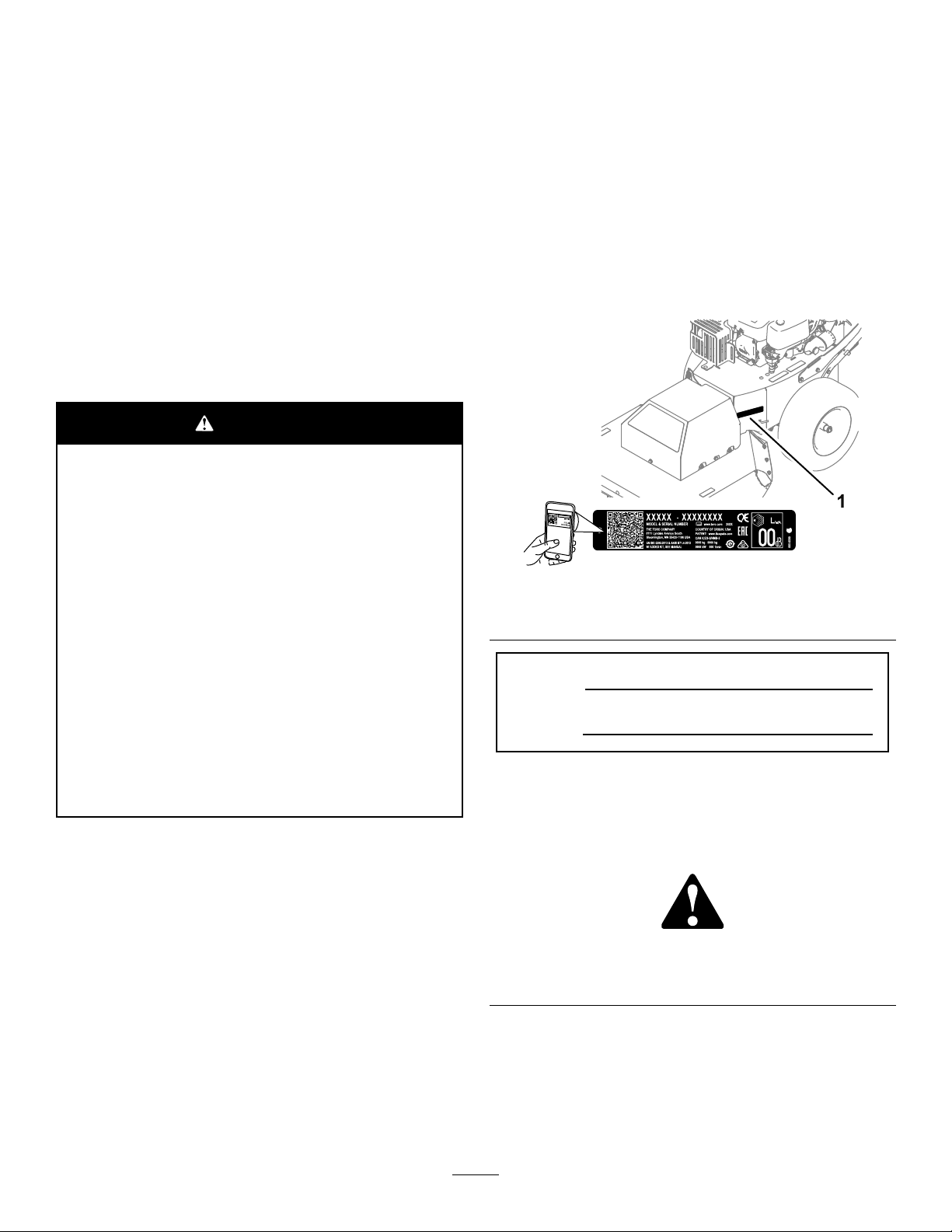
andserialnumbersofyourproductready.Figure1
identiesthelocationofthemodelandserialnumbers
ontheproduct.Writethenumbersinthespace
provided.
Important:Withyourmobiledevice,youcan
scantheQRcode(ifequipped)ontheserial
numberdecaltoaccesswarranty,parts,andother
productinformation.
g248384
Figure1
1.Modelandserialnumberlocation
ModelNo.
SerialNo.
Thismanualidentiespotentialhazardsandhas
safetymessagesidentiedbythesafety-alertsymbol
(Figure2),whichsignalsahazardthatmaycause
seriousinjuryordeathifyoudonotfollowthe
recommendedprecautions.
Introduction
Thismachineisdesignedtolevelbrush,tallweeds,
saplings,andsmalltreesandheavyvegetationupto
1.8m(6feet)talland5.1cm(2inches)indiameter.
Readthisinformationcarefullytolearnhowtooperate
andmaintainyourproductproperlyandtoavoid
injuryandproductdamage.Youareresponsiblefor
operatingtheproductproperlyandsafely .
YoumaycontactTorodirectlyatwww.T oro.com
forproductsafetyandoperationtrainingmaterials,
©2018—TheToro®Company
8111LyndaleAvenueSouth
Bloomington,MN55420
Figure2
1.Safety-alertsymbol
Thismanualuses2wordstohighlightinformation.
Importantcallsattentiontospecialmechanical
informationandNoteemphasizesgeneralinformation
worthyofspecialattention.
2
g000502
Contactusatwww.Toro.com.
PrintedintheUSA
AllRightsReserved
Page 3

Contents
Safety.......................................................................4
GeneralSafety...................................................4
SafetyandInstructionalDecals..........................4
Setup........................................................................6
1InstallingtheHandle........................................6
2ConnectingtheNegativeBattery
Cable..............................................................7
ProductOverview.....................................................8
Controls.............................................................8
Specications..................................................10
Attachments/Accessories.................................10
BeforeOperation.................................................10
BeforeOperationSafety...................................10
FuelSpecication..............................................11
UsingStabilizer/Conditioner..............................11
FillingtheFuelTank...........................................11
CheckingtheEngine-OilLevel...........................11
DuringOperation..................................................11
DuringOperatingSafety....................................11
StartingandShuttingOfftheEngine.................12
OperatingtheTractionControl..........................13
OperatingtheBlade-ControlClutch..................13
AfterOperation....................................................13
AfterOperationSafety......................................13
MovingaNonfunctioningMachine....................14
TransportingtheMachine.................................14
Maintenance...........................................................15
RecommendedMaintenanceSchedule(s)...........15
MaintenanceSafety..........................................15
EngineMaintenance...........................................16
EngineSafety...................................................16
ServicingtheAirCleaner..................................16
ServicingtheEngineOil....................................17
ServicingtheSparkPlug...................................19
FuelSystemMaintenance...................................20
ReplacingtheIn-LineFuelFilter.......................20
ElectricalSystemMaintenance...........................21
ElectricalSystemSafety...................................21
RemovingtheBattery.......................................21
ChargingtheBattery.........................................22
InstallingtheBattery.........................................22
ServicingaReplacementBattery......................23
DriveSystemMaintenance..................................23
CheckingtheTirePressure...............................23
CoolingSystemMaintenance..............................24
CleaningtheEngineScreen.............................24
CleaningtheEngine-CoolingFinsand
Shrouds........................................................24
BeltMaintenance................................................24
InspectingtheBelts..........................................24
ReplacingtheTransmissionBelt.......................24
ReplacingtheMowerBelt.................................25
MowerMaintenance.............................................26
BladeSafety.....................................................26
BeforeInspectingorServicingthe
Blade.............................................................26
InspectingtheBlade.........................................26
CheckingforaBentBlade................................26
RemovingtheBlade.........................................27
SharpeningtheBlade.......................................27
InstallingtheBlade...........................................28
Cleaning..............................................................28
RemovingDebrisfromtheMachine..................28
Storage...................................................................29
StoringtheMachine..........................................29
Troubleshooting......................................................30
3
Page 4
Safety
Thismachinehasbeendesignedinaccordancewith
EN12733.
GeneralSafety
Thisproductiscapableofamputatinghandsand
feetandofthrowingobjects.Alwaysfollowallsafety
instructionstoavoidseriouspersonalinjury.
Usingthisproductforpurposesotherthanitsintended
usecouldprovedangeroustoyouandbystanders.
•Read,understand,andfollowtheinstructions
andwarningsinthisOperator’sManualandon
themachineandattachmentsbeforestartingthe
engine.
•Useyourfullattentionwhileoperatingthe
machine.Donotengageinanyactivitythat
causesdistractions;otherwise,injuryorproperty
damagemayoccur.
•Donotputyourhandsorfeetnearmovingpartsof
orunderthemachine.Keepclearofanydischarge
opening.
•Donotoperatethemachinewithoutallguards
andothersafetyprotectivedevicesinplaceand
workingonthemachine.
•Keepbystandersandchildrenasafedistance
awayfromthemachine.Donotallowchildrento
operatethemachine.Allowonlypeoplewhoare
responsible,trained,familiarwiththeinstructions,
andphysicallycapabletooperatethemachine.
•Stopthemachine,shutofftheengine,remove
theelectric-startkey(ifequipped),andwaitforall
movingpartstostopbeforeservicing,fueling,or
uncloggingthemachine.
Improperlyusingormaintainingthismachinecan
resultininjury .T oreducethepotentialforinjury,
complywiththesesafetyinstructionsandalwayspay
attentiontothesafety-alertsymbol,whichmeans
Caution,Warning,orDanger—personalsafety
instruction.Failuretocomplywiththeseinstructions
mayresultinpersonalinjuryordeath.
Youcanndadditionalsafetyinformationwhere
neededthroughoutthismanual.
SafetyandInstructionalDecals
Safetydecalsandinstructionsareeasilyvisibletotheoperatorandarelocatednearanyarea
ofpotentialdanger.Replaceanydecalthatisdamagedormissing.
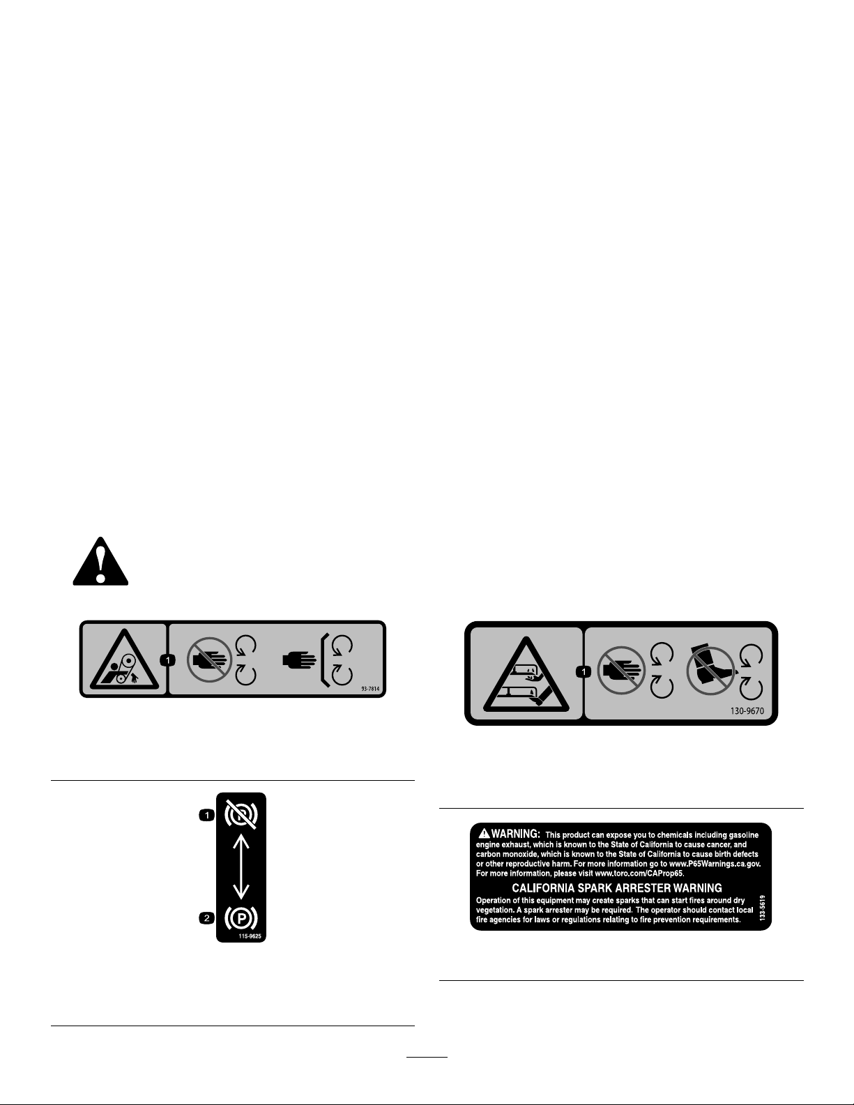
93-7814
1.Entanglementhazard,belt—stayawayfrommovingparts;
keepallguardsandshieldsinplace.
decal93-7814
decal130-9670
130-9670
1.Severinghazardofhandorfoot;mowerblade—keepaway
frommovingparts.
decal115-9625
115-9625
1.Parking
brake—disengaged
2.Parkingbrake—engaged
4
133-5619
decal133-5619
Page 5
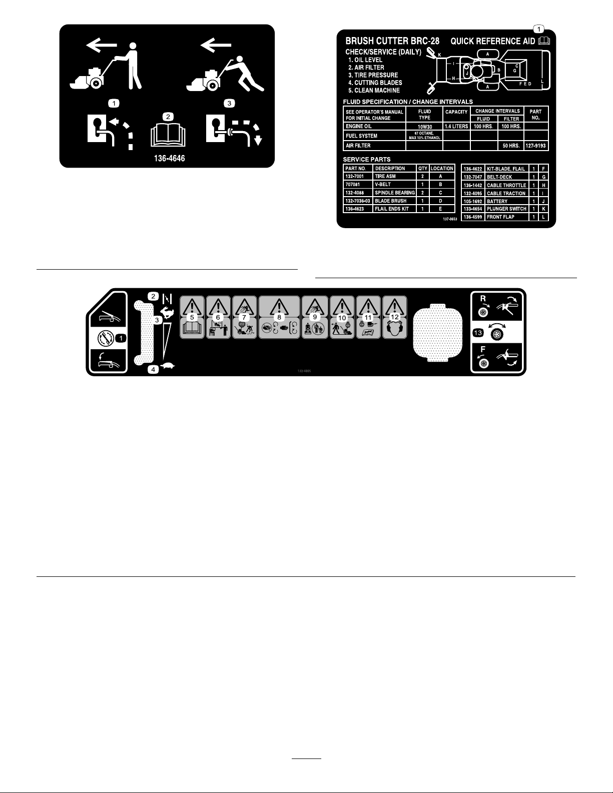
decal136-4646
136-4646
1.Whenthemachinehas
power,disengagethe
bypassandtransportthe
machinenormally.
3.Whenthemachinehasno
power,engagethebypass
andpushthemachineto
transportit.
2.ReadtheOperator's
Manual.
1.ReadtheOperator’sManual.
132-4005
1.Cuttingbladecontrol6.Warning—trainalloperatorsbefore
2.Choke7.Thrownobjecthazard—shutoffthe
3.Fastenginespeed
4.Slowenginespeed
5.Warning—readtheOperator’sManual.10.Warning—shutofftheenginebefore
theyoperatethemachine.
engineandpickupdebrisbefore
operating.
8.Warning—keepawayfrommoving
parts;keepallguardsandcoversin
place.
9.Thrownobjecthazard—keep
bystandersasafedistancefromthe
machine.
leavingtheoperatorposition.
decal137-0653
137-0653
decal132-4005
11.Warning—shutofftheengine,
disconnectthesparkplug,andreadthe
Operator'sManualbeforeperforming
maintenance.
12.Warning—wearhearingprotection.
13.Tractiondrivecontrol
5
Page 6
Setup
LooseParts
Usethechartbelowtoverifythatallpartshavebeenshipped.
ProcedureDescription
1
2
1
InstallingtheHandle
Partsneededforthisprocedure:
1
Cabletie
4Handlebolt
4
Nut(5/16inch)
2
Slotted-headbolt(#10)
2
Locknut(#10)
Procedure
Cabletie
Handlebolt4
Nut(5/16inch)
Slotted-headbolt(#10)
Locknut(#10)
Nopartsrequired
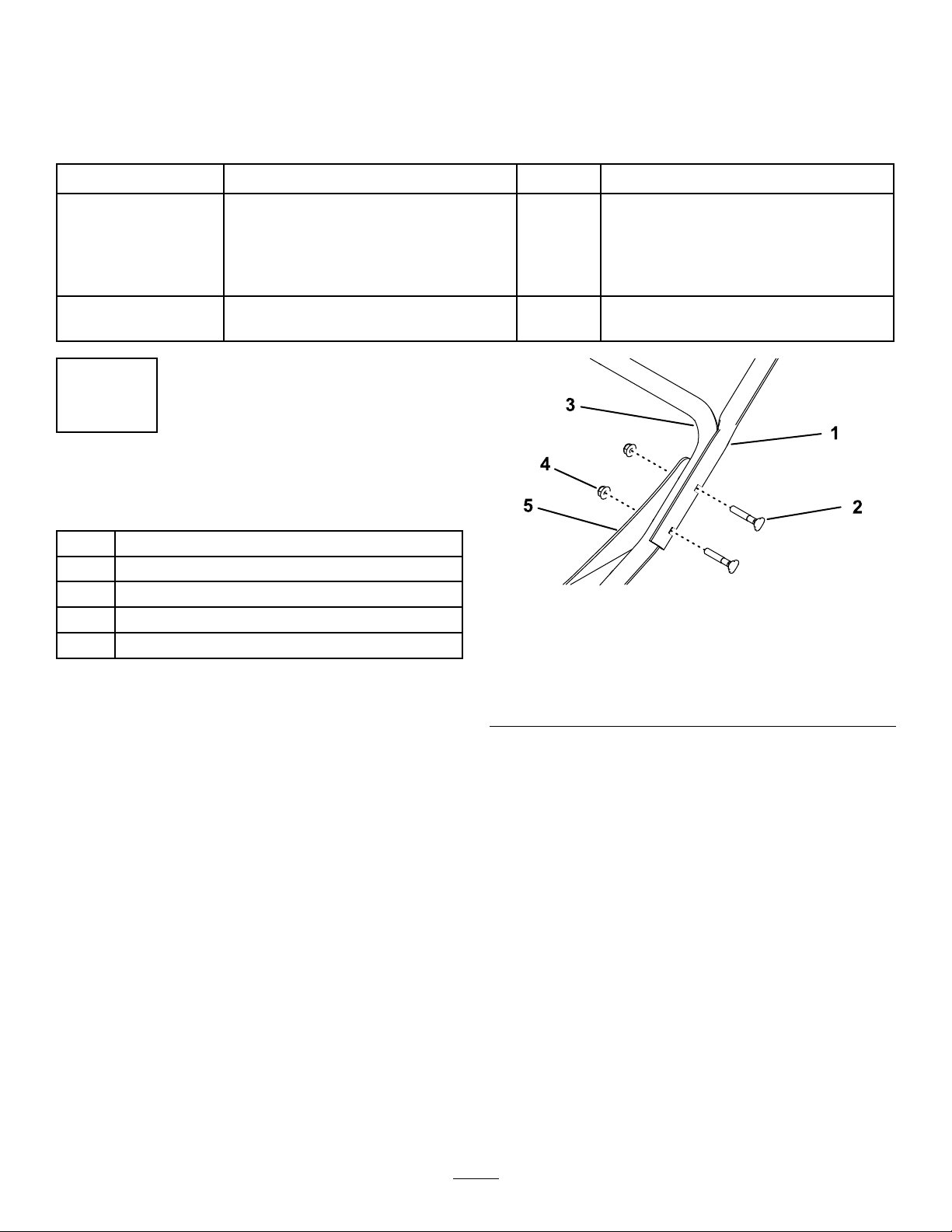
1.Upperhandletube
2.Handlebolt5.Brace
3.Lowerhandle
Qty.
Use
1
4
2
2
–
Installthehandle.
Connectthenegativebatterycable.
g194930
Figure3
Leftsideshown
4.Nut(5/16inch)
1.Installtheupperhandletubestothelower
handleandbracesusing2handleboltsand2
nuts(5/16inch)onbothsidesofthemachine
(Figure3).
2.Securethethrottlecableoverthelowerhandle
usingacabletie(Figure4).
6
Page 7
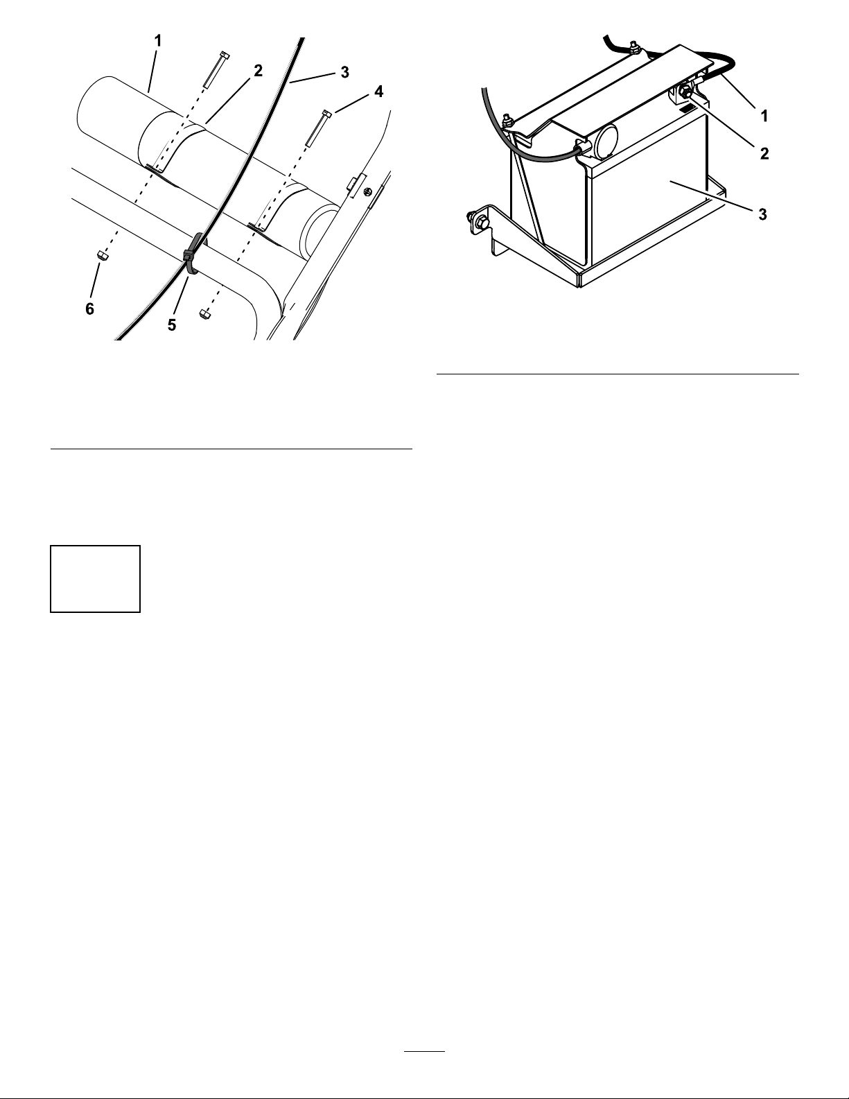
Figure5
g195546
Figure4
1.Operator’sManualtube4.Slotted-headbolt(2)
2.Clamp(2)5.Cabletie
3.Throttlecable
3.SlidetheclampsontotheOperator’sManual
tubeandinstallitontopofthelowerhandle
using2slotted-headboltsand2locknuts(Figure
4).
6.Locknut(2)
2
ConnectingtheNegative BatteryCable
NoPartsRequired
g195541
1.Negativebatterycable3.Battery
2.Boltandnut
Procedure
1.Removetheplasticcapfromthenegative
batteryterminal.
2.Connectthenegativebatterycabletothe
negative(-)batterypostusingtheboltandnut
attachedtothecable(Figure5).
7
Page 8
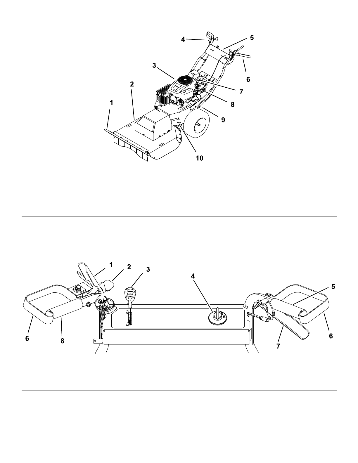
ProductOverview
g186623
Figure6
1.Brushbar4.Righthandgripandtraction
2.Cutterdeck5.Controlpanel8.Fuel-shutoffvalve
3.Engine
control
6.Lefthandgripand
blade-controlclutch
7.Fuel-tankcap10.Bypasslever
9.Parkingbrake
Controls
Becomefamiliarwithallthecontrols(Figure6andFigure7)beforeyoustarttheengineandoperatethe
machine.
1.Blade-controlclutch
2.Safetylatch
Figure7
3.Throttle/chokecontrol
4.Ignitionswitch6.Handguard
5.Righthandgrip7.Tractioncontrol
8
g186771
8.Lefthandgrip
Page 9
Blade-ControlClutch
Usetheblade-controlclutchtoengageanddisengage
themowerblade.
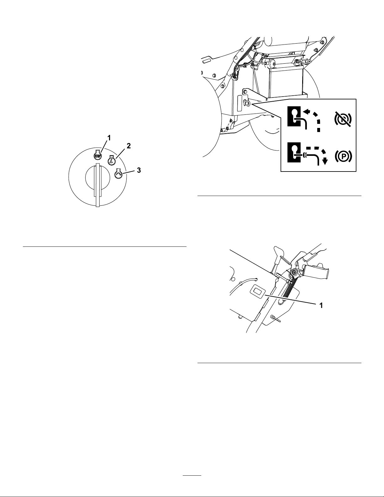
IgnitionSwitch
Theignitionswitchhas3positions:OFF,RUN,and
START.ThekeyturnstoSTARTandmovesback
toRUNuponrelease.TurningthekeytotheOFF
(“STOP”)positionshutsofftheengine;however,
alwaysremovethekeyfromtheignitionswitch
whenleavingthemachinetopreventsomeonefrom
accidentallystartingtheengineandtopreventthe
batteryfrominadvertentlydraining(Figure8).
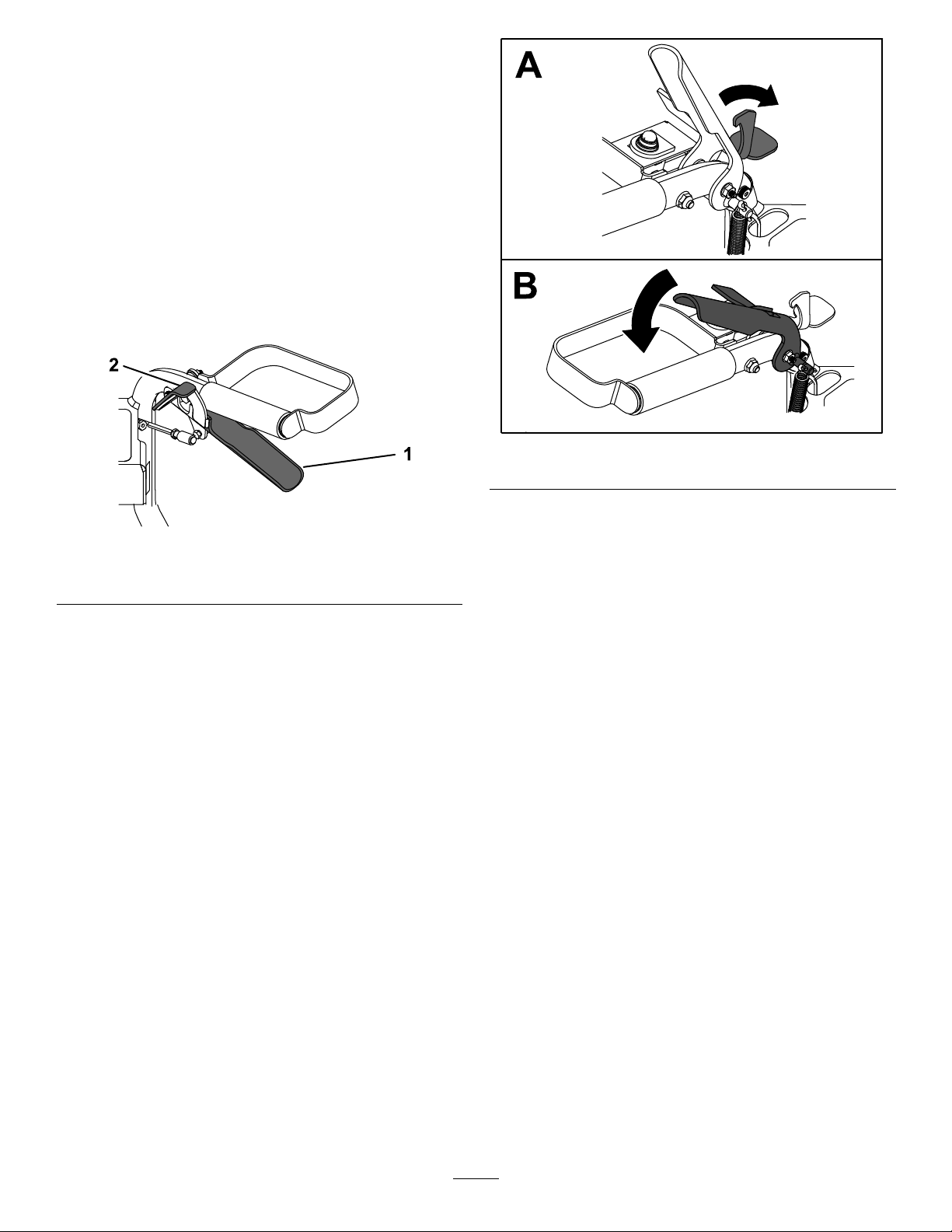
(Figure9).Disengagetheparkingbrakebyliftingthe
leverandpushitinwardthroughthekeyhole.
g195543
Figure9
Figure8
1.Offposition3.Startposition
2.Runposition
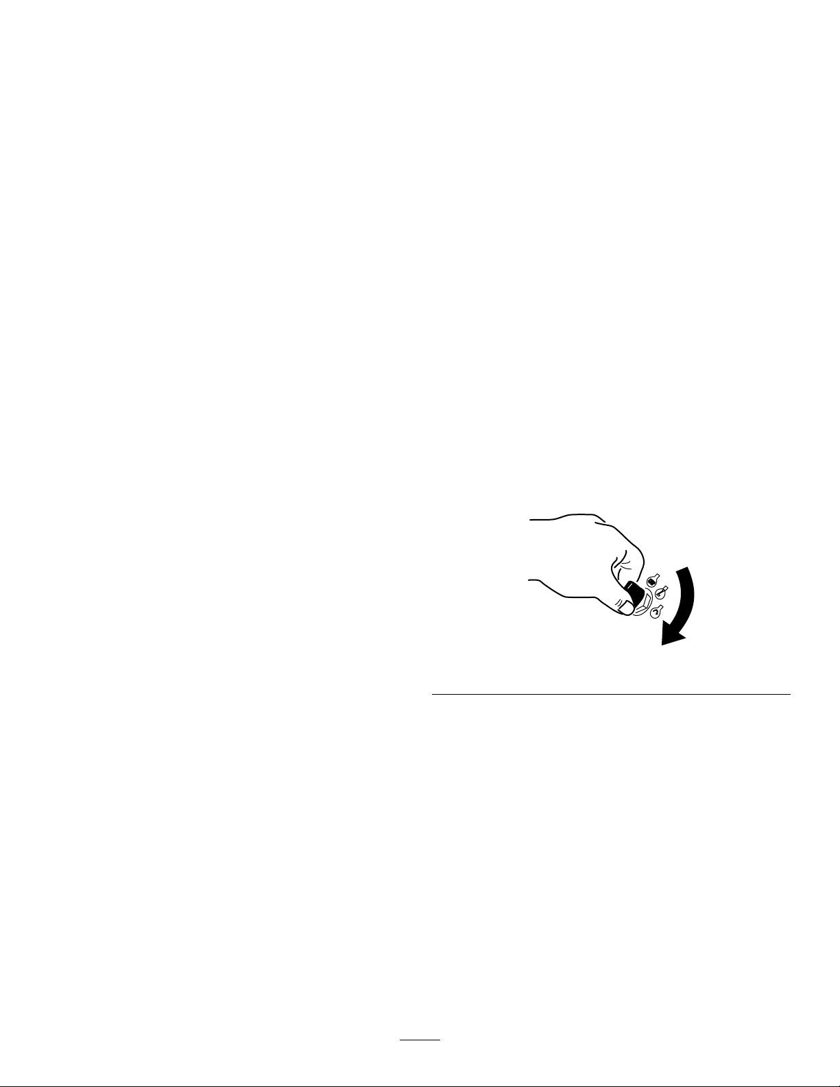
Throttle/ChokeLever
1levercontrolsboththethrottleandthechoke.
Thethrottlecontrolstheenginespeedandhas
acontinuous-variablesettingfromSLOWtoFAST.
EngagethechokebymovingtheleverpasttheFAST
settinguntilitstops
TractionControl
Usethetractioncontroltomovethemachineforward
andrearwardwithcontinuouslyvariablespeed.
Fuel-ShutoffValve
Closethefuel-shutoffvalvefortransport,maintenance,
andstorage.
g192199
HourMeter
Thehourmeterdisplaysthenumberofhoursof
operationloggedonthemachine(Figure10).
g186773
Figure10
1.Hourmeter
Ensurethatthefuel-shutoffvalveisopenwhen
startingtheengine.
ParkingBrake
Theparkingbrakeislocatednearthebattery.T o
engagetheparkingbrake,pulltheleveroutward
throughthekeyholeanddowntolockitinplace
9
Page 10

Specications
Note:Specicationsanddesignaresubjectto
changewithoutnotice.
Length
Width
Height
Weight
Cuttingwidth71cm(28inches)
Attachments/Accessories
AselectionofT oroapprovedattachmentsand
accessoriesisavailableforusewiththemachineto
enhanceandexpanditscapabilities.Contactyour
AuthorizedServiceDealerorDistributororgoto
www.T oro.comforalistofallapprovedattachments
andaccessories.
Toensureoptimumperformanceandcontinuedsafety
certicationofthemachine,useonlygenuineT oro
replacementpartsandaccessories.Replacement
partsandaccessoriesmadebyothermanufacturers
couldbedangerous,andsuchusecouldvoidthe
productwarranty.
227cm(89inches)
88cm(35inches)
101cm(40inches)
171kg(376lb)
Operation
BeforeOperation
Note:Determinetheleftandrightsidesofthe
machinefromthenormaloperatingposition.
BeforeOperationSafety
GeneralSafety
•Becomefamiliarwiththesafeoperationofthe
equipment,operatorcontrols,andsafetysigns.
•Checkthatallguardsandsafetydevices,suchas
deectorsand/orgrasscatcher,areinplaceand
workingproperly.
•Alwaysinspectthemachinetoensurethatthe
blades,bladebolts,andcuttingassemblyarenot
wornordamaged.
•Inspecttheareawhereyouwillusethemachine,
andremoveallobjectsthatcouldinterferewith
theoperationofthemachineorthatthemachine
couldthrow.
FuelSafety
•Fuelisextremelyammableandhighlyexplosive.
Areorexplosionfromfuelcanburnyouand
othersandcandamageproperty.
–Topreventastaticchargefromignitingthefuel,
placethecontainerand/ormachinedirectlyon
thegroundbeforelling,notinavehicleoron
anobject.
–Fillthefueltankoutdoors,inanopenarea,
whentheengineiscold.Wipeupanyfuelthat
spills.
–Donothandlefuelwhensmokingoraroundan
openameorsparks.
–Donotremovethefuelcaporaddfueltothe
tankwhiletheengineisrunningorhot.
–Ifyouspillfuel,donotattempttostartthe
engine.Avoidcreatingasourceofignitionuntil
thefuelvaporshavedissipated.
–Storefuelinanapprovedcontainerandkeep
itoutofthereachofchildren.
•Fuelisharmfulorfatalifswallowed.Long-term
exposuretovaporscancauseseriousinjuryand
illness.
–Avoidprolongedbreathingofvapors.
–Keepyourhandsandfaceawayfromthe
nozzleandthefuel-tankopening.
–Keepfuelawayfromyoureyesandskin.
10
Page 11

FuelSpecication
CheckingtheEngine-Oil
Petroleum
fuel
Ethanol
blended
fuel
Useunleadedgasolinewithanoctaneratingof87
orhigher((R+M)/2ratingmethod).
Useanunleaded-gasolineblendwithupto10%
ethanol(gasohol)or15%MTBE(methyltertiary
butylether)byvolumeisacceptable.Ethanoland
MTBEarenotthesame.
Gasolinewith15%ethanol(E15)byvolumeis
notapprovedforuse.Neverusegasolinethat
containsmorethan10%ethanolbyvolume,such
asE15(contains15%ethanol),E20(contains
20%ethanol),orE85(containsupto85%
ethanol).Usingunapprovedgasolinemaycause
performanceproblemsand/orenginedamage
whichmaynotbecoveredunderwarranty.
Important:Forbestresults,useonlyclean,fresh
fuel(lessthan30daysold).
•Donotusegasolinecontainingmethanol.
•Donotstorefueleitherinthefueltankorfuel
containersoverthewinterunlessyouuseafuel
stabilizer.
•Donotaddoiltogasoline.
Using Stabilizer/Conditioner
Useafuelstabilizer/conditionerinthemachineto
providethefollowingbenets:
Important:Donotusefueladditivescontaining
methanolorethanol.
Addthecorrectamountoffuelstabilizer/conditioner
tothegasoline.
Note:Afuelstabilizer/conditionerismosteffective
whenmixedwithfreshgasoline.T ominimizethe
chanceofvarnishdepositsinthefuelsystem,usefuel
stabilizeratalltimes.
FillingtheFuelTank
1.Parkthemachineonalevelsurfaceandshut
offtheengine.
2.Allowtheenginetocool.
3.Cleanaroundthefuel-tankcapandremoveit
(Figure6).
4.Addfueltothefueltankuntiltheleveloffuelis
atthebottomofthellerneck.
5.Installthefuel-tankcapsecurely.
6.Wipeupanyfuelthatmayhavespilled.
Level
Beforeyoustarttheengineandusethemachine,
checktheoillevelintheenginecrankcase;referto
CheckingtheEngine-OilLevel(page17).
DuringOperation
DuringOperatingSafety
GeneralSafety
•Wearappropriateclothingincludingeyeprotection;
hearingprotection;protectivegloves;longpants;
andsubstantial,slip-resistantfootwear.Tieback
longhair,securelooseclothing,anddonotwear
loosejewelry.
•Donotoperatethemachinewhileill,tired,or
undertheinuenceofalcoholordrugs.
•Thebladeissharp;contactingthebladecanresult
inseriouspersonalinjury.Shutofftheengine,
removetheignitionkey(ifequiped),andwaitforall
movingpartstostopbeforeleavingtheoperating
position.
•Keepbystanders,especiallysmallchildren,outof
theoperatingarea.Stopthemachineifanyone
entersthearea.
•Alwayslookdownandbehindyoubeforemoving
themachineinreverse.
•Operatethemachineonlyingoodvisibilityand
appropriateweatherconditions.Donotoperate
themachinewhenthereistheriskoflighting.
•Wetgrassorleavescancauseseriousinjuryif
youslipandcontacttheblade.Avoidmowingin
wetconditions.
•Useextremecarewhenapproachingblind
corners,shrubs,trees,orotherobjectsthatmay
blockyourview.
•Watchforholes,ruts,bumps,rocks,orother
hiddenobjects.Uneventerraincouldcausethe
machinetooverturnorcauseyoutoloseyour
balanceorfooting.
•Ifthemachinestrikesanobjectorstartstovibrate,
immediatelyreleasetheblade-controlclutch,
shutofftheengine,removethekey,waitforall
movingpartstostop,anddisconnectthewire
fromthesparkplugbeforeexaminingthemachine
fordamage.Makeallnecessaryrepairsbefore
resumingoperation.
•Beforeleavingtheoperatingposition,shutoffthe
engine,removetheignitionkey,andwaitforall
movingpartstostop.
11
Page 12
•Iftheenginehasbeenrunningthemuferwillbe
hotandcanseverelyburnyou.Keepawayfrom
thehotmufer.
•Checkthereardeckapfrequentlyforany
wearordeteriorationandreplacethemwith
themanufacturer'srecommendedpartswhen
necessary.
•Useaccessoriesandattachmentsapprovedby
TheT oro®Companyonly.
•Ifyoulosecontrolofthemachine,stepawayfrom
thedirectionoftravelofthemachine.
•Usethetractioncontroltoslowthemachinewhen
goingdownslopes.Donotfullyengagethe
tractioncontroldownhill.
StartingandShuttingOff theEngine
SlopeSafety
•Slopesareamajorfactorrelatedtolossofcontrol
androlloveraccidents,whichcanresultinsevere
injuryordeath.Theoperatorisresponsiblefor
safeslopeoperation.Operatingthemachineon
anysloperequiresextracaution.Beforeusingthe
machineonaslope,theoperatormust:
–Reviewandunderstandtheslopeinstructions
inthemanualandonthemachine.
–Evaluatethesiteconditionsofthedayto
determineiftheslopeissafeformachine
operation.Usecommonsenseandgood
judgmentwhenperformingthisevaluation.
Changesintheterrain,suchasmoisture,can
quicklyaffecttheoperationofthemachineon
aslope.
•Operateacrossslopes,neverupanddown.Avoid
operationonexcessivelysteeporwetslopes.
Poorfootingcouldcauseaslipandfallaccident.
•Identifyhazardsatthebaseoftheslope.Do
notoperatethemachineneardrop-offs,ditches,
embankments,waterorotherhazards.The
machinecouldsuddenlyrolloverifawheelgoes
overtheedgeortheedgecollapses.Keepasafe
distancebetweenthemachineandanyhazard.
Useahandheldtooltoworkintheseareas.
StartingtheEngine
Note:Youmayneedmultipleattemptstostartthe
enginewhenyoustartitthersttimeorafterthe
enginehasrunoutoffuelcompletely .
1.MovethethrottleleverforwardpasttheFAST
positionandholditagainsttheforwardstopto
activatethechoke.
2.TurntheignitionkeytotheSTARTposition
(Figure11).
Important:Donotengagethestarterfor
morethan5secondsatatime.Iftheengine
failstostart,wait15secondsbetween
attempts.Failuretofollowtheseinstructions
canburnoutthestartermotor.
g192135
Figure11
•Avoidstarting,stopping,orturningthemachineon
slopes.Avoidmakingsuddenchangesinspeedor
direction;turnslowlyandgradually.
•Donotoperateamachineunderanyconditions
wheretraction,steeringorstabilityisinquestion.
Beawarethatoperatingthemachineonwet
grass,acrossslopesordownhillmaycausethe
machinetolosetraction.Lossoftractiontothe
drivewheelsmayresultinslidingandalossof
brakingandsteering.Themachinecanslideeven
ifthedrivewheelsarestopped.
•Removeormarkobstaclessuchasditches,holes,
ruts,bumps,rocksorotherhiddenhazards.T all
grasscanhideobstacles.Uneventerraincould
overturnthemachine.
3.Whentheenginestarts,releasethekeyand
movethethrottleleverbacktotheFASTposition.
ShuttingOfftheEngine
1.Releasetheblade-controlclutchtodisengage
theblade.
2.TurntheignitionkeytotheSTOPpositiontoshut
offtheengineandremovethekey.
12
Page 13
OperatingtheTraction Control
Tomovethemachineforward,squeezethetraction
controltowardthehandgrip(Figure12).
Tomovethemachinerearward,pushthethumbpad
downtomovethetractioncontrolawayfromthehand
grip(Figure12).
Themoreyoumovethetractioncontrolineither
direction,thefasterthemachinemovesinthat
direction.
Todisengagethetractiondrive,releasethetraction
control.
g188811
Figure13
Figure12
1.Tractioncontrol2.Thumbpad
Operatingthe Blade-ControlClutch
Thismachineiscapableofcuttingbrushandsaplings
upto1.8m(6feet)talland5.1cm(2inches)in
diameter.Thecuttingdeckpivotstofollowthecontour
ofthegroundasyoumovethemachine.
Toengagetheblade,useyourrighthandtoopenthe
safetylatchandthenuseyourlefthandtosqueeze
theblade-controlclutchtothelefthandle(Figure12).
Todisengagetheblade,releasetheblade-control
clutch.
g186864
AfterOperation
AfterOperationSafety
GeneralSafety
•Cleangrassanddebrisfromthemachinetohelp
preventres.Cleanupoilorfuelspills.
•Shutofftheengine,andremovethekey.Wait
forallmovementtostopandallowthemachine
tocoolbeforecleaning,adjusting,repairing,or
storingthemachineinanyenclosure.
•Neverstorethemachineorfuelcontainerwhere
thereisanopename,spark,orpilotlight,such
asonawaterheateroronotherappliances.
HaulingSafety
•Removetheignitionkey(ifequipped)before
loadingthemachineforhauling.
•Usecarewhenloadingorunloadingthemachine.
•Securethemachinefromrolling.
13
Page 14

MovingaNonfunctioning Machine
1.Parkthemachineonalevelsurfaceand
disengagetheblade-controlclutch.
2.Engagetheparkingbrake,shutofftheengine,
removethekey,andwaitforallmovingparts
tostop.
3.Movethebypassleveroutwardthroughthe
keyholeanddowntolockitinplace.
4.Disengagetheparkingbrake.
5.Pushthemachineasrequired.
6.Engagetheparkingbrake.
7.Movethebypassleverupandinwardthrough
thekeyholetodisengagethebypass.
trailerortruckwithstraps,chains,cable,or
ropes(Figure15).
g188889
Figure15
Figure14
TransportingtheMachine
Useaheavy-dutytrailerortrucktotransportthe
machine.Ensurethatthetrailerortruckhasall
necessarybrakes,lighting,andmarkingasrequired
bylaw.Pleasecarefullyreadallthesafetyinstructions.
Knowingthisinformationcouldhelpyou,yourfamily,
pets,orbystandersavoidinjury.
1.Lefttie-downloop
g188886
g188887
2.Brushbar
1.Ifusingatrailer,connectittothetowingvehicle
andconnectthesafetychains.
2.Ifapplicable,connectthetrailerbrakes.
3.Loadthemachineontothetrailerortruck.
4.Shutofftheengine,removethekey,engagethe
parkingbrake,andclosethefuelvalve.
5.Usethebrushbarand2tie-downloopsonthe
machinetosecurelyfastenthemachinetothe
14
Page 15

Maintenance
Note:Determinetheleftandrightsidesofthemachinefromthenormaloperatingposition.
RecommendedMaintenanceSchedule(s)
MaintenanceService
Interval
Aftertherst5hours
Beforeeachuseordaily
Every25hours
Every50hours
Every100hours
Beforestorage
MaintenanceProcedure
•Changetheengineoilandlter.
•Cleanandchecktheair-cleanerfoamandpaperelements.
•Checktheengine-oillevel.
•Inspecttheconditionofthetires.
•Cleantheengineair-intakescreen.
•Inspecttheblade.
•Removedebrisfromthemachine.
•Checktirepressure.
•Checkthebeltsforwear/cracks.
•Replacetheair-cleanerfoamandpaperelements.
•Checkthesparkplug.
•Changetheengineoilandlter(changeitmoreoftenunderaheavyloadorin
hightemperatures).
•Replacethesparkplug.
•Replacethein-linefuellter.
•Cleantheengine-coolingnsandshrouds.
•Chargethebatteryanddisconnectbatterycables.
•Changetheengineoilandlter.
•Servicetheaircleaner.
•Emptythefueltank.
•Lubricateinsidetheenginecylinder.
CAUTION
Ifyouleavethekeyintheswitch,someonecouldaccidentlystarttheengineandseriously
injureyouorotherbystanders.
Removethekeyfromtheswitchbeforeyouperformanymaintenance.
MaintenanceSafety
•Disconnectthespark-plugwirefromthesparkplugbeforeperforminganymaintenanceprocedure.
•Wearglovesandeyeprotectionwhenservicingthemachine.
•Thebladeissharp;contactingthebladecanresultinseriouspersonalinjury.Weargloveswhenservicing
theblade.
•Nevertamperwithsafetydevices.Checktheirproperoperationregularly.
•Tippingthemachinemaycausethefueltoleak.Fuelisammableandexplosive,andcancausepersonal
injury.Runtheenginedryorremovethefuelwithahandpump;neversiphonthefuel.
15
Page 16

EngineMaintenance
EngineSafety
Shutofftheenginebeforecheckingtheoiloradding
oiltothecrankcase.
ServicingtheAirCleaner
ServiceInterval:Beforeeachuseordaily—Clean
andchecktheair-cleanerfoamand
paperelements.
Every50hours—Replacetheair-cleanerfoam
andpaperelements.
Note:Servicetheaircleanermorefrequentlyifthe
operatingconditionsareextremelydustyorsandy .
RemovingtheFoamandPaper Elements
g037326
Figure17
1.Foamelement3.Nuts
2.Paperelement
5.Carefullyremovethefoamandpaper-lter
elementsfromtheair-cleanerhousing.
6.Separatethefoamandpaperelements.
1.Parkthemachineonalevelsurface,shutoffthe
engine,waitforallmovingpartstostop,and
removethekeyfromtheignitionswitchbefore
leavingtheoperatingposition.
2.Cleanaroundtheaircleanertopreventdirtfrom
gettingintotheengineandcausingdamage.
3.Removetheair-cleanercoverbyunscrewingthe
2knobs(Figure16).
Figure16
1.Air-cleanercover2.Knobs
4.Removethe2nutssecuringthelterassembly
tothehousing(Figure17).
CleaningtheFoamandPaper Elements
FoamElement:
1.Washthefoamelementinliquidsoapandwarm
water.
2.Whentheelementisclean,rinseitthoroughly.
3.Drytheelementbysqueezingitinacleancloth.
Note:Donotoiltheelement.
Important:Replacethefoamelementifit
istornorworn.
4.Installthefoamelementontoacleanpaper
element.
PaperElement:
1.Tapthepaperelementonasolid,atsurface,
andblowitoutfromtheinsidewithcompressed
airtoremovedustanddirt.
g017862
2.Inspecttheelementfortears,anoilylm,and
damagetotherubberseal.
Important:Donotcleanthepaperelement
withliquids,suchassolvents,gasoline,or
kerosene.Replacethepaperelementifitis
damagedorcannotbecleanedthoroughly.
3.Cleantheinsideoftheair-cleanercoverofall
dirt,dust,anddebris.
16
Page 17

InstallingtheFoamandPaper Elements
Important:Topreventenginedamage,always
operatetheenginewiththecompletefoamand
paper-aircleanerassemblyinstalled.
1.Installthefoamlterontothepaperlter(Figure
17).
2.Installthefoamandpaperlterintothe
air-cleanerhousing.
3.Securethelterassemblytothehousingusing
the2nuts(Figure17).
4.Installtheair-cleanercoverandtightenthe2
knobs(Figure16).
ServicingtheEngineOil
EngineOilSpecication
OilType:Detergentoil(APIserviceSJ,orhigher)
CrankcaseCapacity:1.4L(48oz)whenyou
changethelter.
1.Parkthemachineonalevelsurface,shutoffthe
engine,waitforallmovingpartstostop,and
removethekeyfromtheignitionswitchbefore
leavingtheoperatingposition.
2.Checktheengine-oillevel(Figure19).
Viscosity:Seethetablebelow.
Figure18
CheckingtheEngine-OilLevel
ServiceInterval:Beforeeachuseordaily
Note:Checktheoilwhentheengineiscold.
WARNING
Contactwithhotsurfacesmaycausepersonal
injury.
Keephands,feet,face,clothing,andother
bodypartsawaythemuferandotherhot
surfaces.
Important:Donotoverllthecrankcasewithoil
andruntheengine;enginedamagemayresult.
g029683
g029368
Figure19
ChangingtheEngineOilandFilter
ServiceInterval:Aftertherst5hours
Every100hours(changeitmoreoftenundera
heavyloadorinhightemperatures).
Note:Changetheengine-oilltermorefrequently
whentheoperatingconditionsareextremelydusty
orsandy.
1.Parkthemachineonalevelsurface,shutoffthe
engine,waitforallmovingpartstostop,and
removethekeyfromtheignitionswitchbefore
leavingtheoperatingposition.
17
Page 18

2.Draintheoilfromtheengine(Figure20).
Figure20
3.Removetheengine-oillter(Figure21).After
theoilisdrained,installanewoillter.
Note:Ensurethatthenewoil-ltergasket
touchestheengine,andthentightenthelter
anextra3/4turn.
g027477
Figure21
4.Slowlypourapproximately80%ofthespecied
amountofoilintothellhole(Figure22).
5.Allow3to5minutesfortheoiltosettle,then
checktheoillevel(Figure22).
g029369
18
Page 19

RemovingtheSparkPlug
1.Parkthemachineonalevelsurface,shutoffthe
engine,andremovethekeyfromtheignition
switch.
2.Beforeremovingthesparkplug(s),cleanthe
areaaroundthebaseoftheplugtokeepdirt
anddebrisoutoftheengine.
3.Removethesparkplug(Figure23).
Figure23
g027478
Figure22
6.Addoiltothemachinesothattheoillevel
reachesthe“Full”markonthedipstick.
ServicingtheSparkPlug
ServiceInterval:Every50hours—Checkthespark
plug.
Every100hours—Replacethesparkplug.
Ensurethattheairgapbetweenthecenterandside
electrodesiscorrectbeforeinstallingthesparkplug.
Useasparkplugwrenchforremovingandinstalling
thesparkplugandagappingtoolorfeelergaugeto
checkandadjusttheairgap.Installanewsparkplug
ifnecessary.
SparkPlugSpecication
Type:Champion
®
NGK
BPR6ES
®
RC12YC,Autolite
®
3924,or
g027484
CheckingtheSparkPlug
Important:Donotcleanthesparkplug(s).
Alwaysreplacethesparkplug(s)whenithas:a
blackcoating,wornelectrodes,anoilylm,or
cracks.
Note:Ifyouseelightbrownorgrayontheinsulator,
theengineisoperatingproperly.Ablackcoatingon
theinsulatorusuallymeanstheaircleanerisdirty.
Setthegapto0.76mm(0.030inch).
g027479
Figure24
AirGap:0.76mm(0.030inch)
19
Page 20

InstallingtheSparkPlug
Tightenthesparkplugto20N∙m(15ft-lb).
FuelSystem
Maintenance
DANGER
Incertainconditions,gasolineisextremely
ammableandhighlyexplosive.Areor
explosionfromgasolinecanburnyou,others,
andcandamageproperty.
•Performanyfuel-relatedmaintenance
whentheengineiscold.Dothisoutdoors
inanopenarea.Wipeupanygasolinethat
spills.
•Neversmokewhendraininggasolineand
stayawayfromanopenameorwherea
sparkmayignitethegasolinefumes.
Figure25
g027480
ReplacingtheIn-LineFuel Filter
ServiceInterval:Every100hours—Replacethe
in-linefuellter.
Neverinstalladirtylterifitisremovedfromthefuel
line.
1.Parkthemachineonalevelsurface,shutoffthe
engine,andremovethekeyfromtheignition
switch.
2.Closethefuel-shutoffvalve.
3.Replacethein-linelter(Figure26).
20
Page 21

ElectricalSystem
Maintenance
ElectricalSystemSafety
•Disconnectthebatterybeforerepairingthe
machine.Disconnectthenegativeterminalrst
g186943
andthepositivelast.Connectthepositiveterminal
rstandthenegativelast.
•Chargethebatteryinanopen,well-ventilated
area,awayfromsparksandames.Unplugthe
chargerbeforeconnectingordisconnectingthe
battery.
•Wearprotectiveclothinganduseinsulatedtools.
RemovingtheBattery
WARNING
Batteryterminalsormetaltoolscouldshort
againstmetalmachinecomponents,causing
sparks.Sparkscancausethebatterygasses
toexplode,resultinginpersonalinjury.
Figure26
•Whenremovingorinstallingthebattery,
donotallowthebatteryterminalstotouch
anymetalpartsofthemachine.
•Donotallowmetaltoolstoshortbetween
thebatteryterminalsandmetalpartsofthe
machine.
g033082
WARNING
Incorrectbattery-cableroutingcoulddamage
themachineandcablescausingsparks.
Sparkscancausethebatterygassesto
explode,resultinginpersonalinjury.
•Alwaysdisconnectthenegative(black)
batterycablebeforedisconnectingthe
positive(red)cable.
•Alwaysconnectthepositive(red)battery
cablebeforeconnectingthenegative
(black)cable.
1.Parkthemachineonalevelsurface,shutoffthe
engine,andremovethekeyfromtheignition
switch.
2.Disconnectthenegative(black)batterycable
fromthebattery.
3.Disconnectthepositive(red)batterycablefrom
thebattery.
21
Page 22

4.Removethenutsandsecuringrodsfromboth
sidesofthebattery ,batterycover,andbattery
tray.
Figure27
ChargingtheBattery
ServiceInterval:Beforestorage—Chargethebattery
anddisconnectbatterycables.
1.Removethebatteryfromthechassis;referto
RemovingtheBattery(page21).
2.Chargethebatteryforaminimumof1hourat
6to10amps.
Note:Donotoverchargethebattery .
3.Whenthebatteryisfullycharged,unplug
thechargerfromtheelectricaloutlet,then
disconnectthechargerleadsfromthebattery
posts(Figure28).
g187024
1.Securingrod(2)
2.Positivebatterycable6.Battery
3.Nut(2)
4.Batterycover
5.Negativebatterycable
7.Redterminalboot
g000538
Figure28
1.Positive(+)batterypost3.Red(+)chargerlead
2.Negative(–)batterypost4.Black(–)chargerlead
InstallingtheBattery
1.Placethebatteryonthetrayandsecureitusing
thebatterycover,2securingrods,and2nuts
(Figure27).
2.Installthepositivebatterycabletothepositive
(+)batterypost.
3.Installthenegativebatterycabletothenegative
(-)batterypost.
4.Slidetheredterminalbootontothepositive
batterypost(Figure27).
22
Page 23

ServicingaReplacement
DriveSystem
Battery
Theoriginalbatteryismaintenance-freeanddoesnot
requireservice.Forservicingareplacementbattery,
refertothebatterymanufacturer’sinstructions.
Maintenance
CheckingtheTirePressure
ServiceInterval:Beforeeachuseordaily
Every25hours—Checktirepressure.
Maintaintheairpressureinthetiresasspecied.
Checkthepressureatthevalvestem(Figure29).
Checkthetireswhentheyarecoldtogetthemost
accuratepressurereading.
Inatethetiresto97kPa(14psi).
g000554
Figure29
1.Valvestem
23
Page 24

CoolingSystem
Maintenance
BeltMaintenance
InspectingtheBelts
CleaningtheEngineScreen
ServiceInterval:Beforeeachuseordaily—Clean
theengineair-intakescreen.
Toensurepropercooling,ensurethattheair-intake
screen,coolingns,andotherexternalsurfacesofthe
enginearekeptcleanatalltimes.
Useadrybrushtocleanaccumulateddebrisfromthe
air-intakescreenandaroundtheengine.
Important:Topreventcontaminatingthefuel
system,donotusewatertocleantheengine.
Cleaningthe Engine-CoolingFinsand Shrouds
ServiceInterval:Every100hours—Cleanthe
engine-coolingnsandshrouds.
1.Parkthemachineonalevelsurface,shutoffthe
engine,andremovethekeyfromtheignition
switch.
ServiceInterval:Every25hours—Checkthebelts
forwear/cracks.
Checkthebeltsforcracks,frayededges,burnmarks,
oranyotherdamage.Replacedamagedbelts.
ReplacingtheTransmission Belt
1.Parkthemachineonalevelsurface,disengage
theblade,andengagetheparkingbrake.
2.TurntheignitionkeytotheOFFposition,remove
thekey ,anddisconnectthesparkplugwirefrom
thesparkplug.
3.Useliftingequipmenttoraisethemachineand
supportitwithjackstands.
4.Removetheextensionspringfromthetension
arm(Figure30).
2.Removetheair-intakescreenandcooling
shrouds.
3.Cleanthedebrisandgrassfromtheengine
parts.
4.Installtheair-intakescreenandcoolingshrouds.
Figure30
Transmissionnotshown
1.Extensionspring4.Tensionpulley
2.Clutchpulley
3.Transmissionpulley6.Tensionarm
5.Removethetransmissionbeltfromthepulleys.
6.Wrapthenewtransmissionbeltaroundthe
clutch,transmission,andtensionpulleys(Figure
30).
5.Belt
g188917
7.Installtheextensionspringontothetensionarm.
24
Page 25

ReplacingtheMowerBelt
1.Parkthemachineonalevelsurface,disengage
theblade,andengagetheparkingbrake.
2.TurntheignitionkeytotheOFFposition,remove
thekey ,anddisconnectthesparkplugwirefrom
thesparkplug.
3.Useliftingequipmenttoraisethemachineand
supportitwithjackstands.
4.Removethetransmissionbelt;refertoReplacing
theTransmissionBelt(page24).
5.Loosentheleftandrightsideboltsafewturns
andloosenthefrontboltuntilthecoverisloose
(Figure31).
g188940
Figure32
Note:Donotremovethebolts.
Figure31
1.Beltcover3.Rightsidebolt
2.Frontbolt
6.Liftthecoverupwardtoremoveit.
7.Detachtheextensionspring(Figure32).
CAUTION
1.Deckpulley2.Extensionspring
8.Removethemowerbeltfromtheclutchpulley.
9.Routethenewbeltaroundtheclutchpulley,
throughthebeltguide,alongtheidlerpulley,and
aroundthedeckpulley(Figure32andFigure
33).
Note:Ensurethatthebeltisseatedcorrectlyon
bothpulleys,withnotwists.Thebeltneedsto
beinthispositionuntilyouinstalltheextension
spring.
g188928
Thespringisundertensionwhen
installedandcancausepersonalinjury .
Wearsafetyglassesandbecarefulwhen
removingthespring.
Figure33
Transmissionnotshown
1.Beltguide3.Mowerbelt
2.Idlerpulley
4.Clutchpulley
10.Installtheextensionspring(Figure32).
11.Lowerthebeltcoverontothedeck,aligningthe
slotsinthecoverwiththesidebolts.Tightenthe
frontbolt,thentightenbothsidebolts(Figure
31).
12.Installthetransmissionbelt;refertoReplacing
theTransmissionBelt(page24).
25
g189063
Page 26

MowerMaintenance
CheckingforaBentBlade
Toensureasuperiorqualityofcut,keeptheblade
sharp.Forconvenientsharpeningandreplacement,
youmaywanttokeepextrabladesonhand.
BladeSafety
Awornordamagedbladecanbreak,andapiece
ofthebladecouldbethrownatyouorbystanders,
resultinginseriouspersonalinjuryordeath.Tryingto
repairadamagedblademayresultindiscontinued
safetycerticationoftheproduct.
•Inspectthebladeperiodicallyforwearordamage.
•Usecarewhencheckingtheblade.Wrapthe
bladeorweargloves,andusecautionwhen
servicingtheblade.Onlyreplaceorsharpenthe
blade;neverstraightenorweldthem.
BeforeInspectingor ServicingtheBlade
1.Parkthemachineonalevelsurface,disengage
theblade,andengagetheparkingbrake.
StraightBladeOnly
WARNING
Abladethatisbentordamagedcouldbreak
apartandcouldseriouslyinjureorkillyouor
bystanders.
•Alwaysreplaceabentordamagedblade
withanewblade.
•Donotleorcreatesharpnotchesinthe
edgesorsurfacesoftheblade.
1.Rotatethebladeuntiltheendsfaceforwardand
backward.
2.Fromalevelsurface,measurethedistance
tothecuttingedgeatpositionAoftheblade
(Figure35).
2.TurntheignitionkeytotheOFFposition,remove
thekey,anddisconnectthesparkplugwires
fromthesparkplugs.
3.Tiltthemachinesothatthedeckisoffthe
groundandplacewoodblocksunderthedeck
toholditup.
InspectingtheBlade
ServiceInterval:Beforeeachuseordaily
1.Inspectthecuttingedges(Figure34).
2.Iftheedgesarenotsharporhavenicks,remove
andsharpentheblade;refertoSharpeningthe
Blade(page27).
3.Inspecttheblade.
4.Ifyounoticeanycrackorwear,immediately
installanewblade(Figure34).
Figure35
1.PositionA
3.Rotatetheblade180°.
4.Fromalevelsurface,measurethedistance
tothecuttingedgeofthebladeatthesame
positionasinstep2.
2.Measureherefromblade
tohardsurface.
Note:Thedifferencebetweenthedimensions
obtainedinsteps2and4mustnotexceed3
mm(1/8inch).
Note:Ifthisdimensionexceeds3mm(1/8
inch),thebladeisbentandmustbereplaced.
g189024
Figure34
1.Cuttingedge3.Crack
2.Wear
g248312
26
Page 27

RemovingtheBlade
Replacethebladeifithitsasolidobject,ifthebladeis
outofbalance,orifabladeisbent.Toensureoptimum
performanceandcontinuedsafetyconformanceof
themachine,usegenuineTororeplacementblades.
Replacementbladesmadebyothermanufacturers
mayresultinnonconformancewithsafetystandards.
Note:Flailbladesaresharpenedon2sides,soyou
canturnoverabladewhenyouremoveitforanew
sharpedge
FlailBladeOnly
1.Holdthebladeendusingaragorathickly
paddedglove.
2.Removethebladebolt,thecurvedwasher,and
bladefromtheblademountonthebottomofthe
spindle-cupassembly(Figure36).
StraightBladeOnly
1.Holdthebladeendusingaragorthickly-padded
glove.
2.Removethebladebolt,curvedwasher,and
bladefromthespindlecupassembly(Figure37).
g189023
Figure37
1.Blade3.Bladebolt
2.Curvedwasher
Figure36
1.Nut
2.Flail6.Blade
3.Flailbolt
4.Bladebolt
5.Curvedwasher
7.Spindle-cupassembly
3.T oremoveonlytheailblades,removetheails
fromthebladebyremovingtheailboltandnut
fromeachail.
SharpeningtheBlade
1.Usealetosharpenthecuttingedgeatboth
endsoftheblade(Figure38).
Note:Maintaintheoriginalangle.
g187214
Note:Thebladeretainsbalanceifthesame
amountofmaterialisremovedfrombothcutting
edges.
g192119
Figure38
1.Sharpenattheoriginalangle
27
Page 28
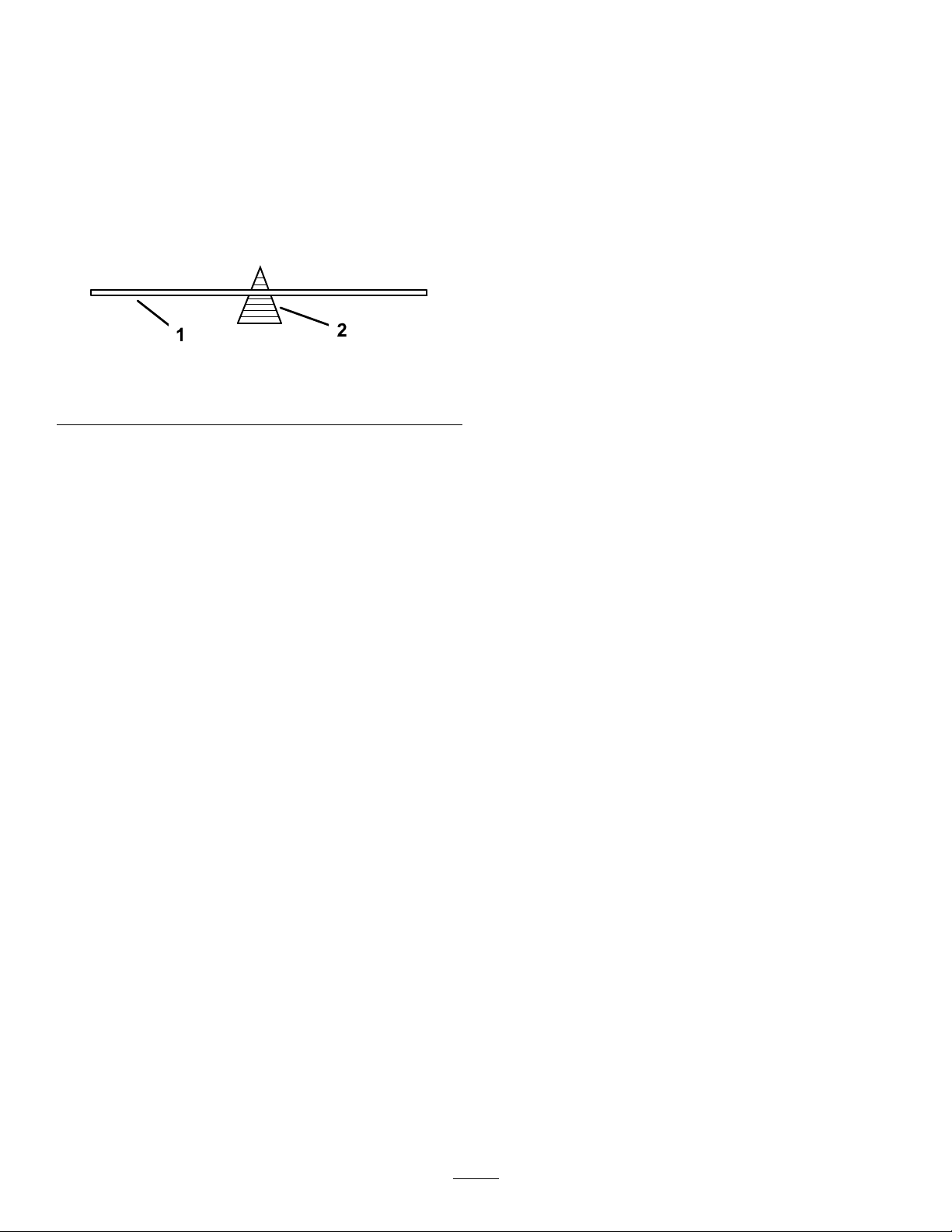
2.Forstraightbladesonly,checkthebalance
ofthebladebyputtingitonabladebalancer
(Figure39).
Cleaning
Ifthebladeisnotbalanced,lesomemetal
offthebacksideoftheblade(oppositeofthe
cuttingedge)only(Figure36).
Repeatthisprocedureuntilthebladeis
balanced.
Note:Ifthebladestaysinahorizontalposition,
thebladeisbalanced.
Figure39
1.Blade2.Balancer
InstallingtheBlade
FlailBladeOnly
1.Attachthebladetothespindlecupassembly
usingthebladeboltandcurvedwasher(Figure
36).
RemovingDebrisfromthe Machine
Regularcleaningandwashingincreasesthelifespan
ofthemachine.Cleanthemachinedirectlyafteruse.
Checkbeforecleaningthatthefueltankcapis
properlyinplacetoavoidgettingwaterinthetank.
Usecarewhenusingahigh-pressuresprayer,
becauseitcandamagewarningdecals,instruction
signs,andtheengine.
g192120
Note:Ensurethatcuppedsideofthewasher
facestheblade,andtheconvexsideofthe
bladefacesthespindlecup.
2.T orquetheboltto136to149N∙m(100to110
ft-lb).
3.T oinstallonlytheailblades,securetheails
totheendofthebladeusingtheailboltanda
newnutforeachail(Figure36).T orquethenut
to103to127N∙m(76to94ft-lb).
Note:Alwaysreplacearemovedailnutwith
anewnut.
Note:Securetheailstothebottomofthe
blade,notthetop.
StraightBladeOnly
1.Installthebladeontothespindleshaft(Figure
37).
Note:Ensurethattheconvexsideoftheblade
facesthespindlecup.
2.Installthecurvedwasher(cuppedsidetoward
theblade)andbladebolt(Figure37).
3.T orquethebladeboltto136to149N∙m(100
to110ft-lb).
28
Page 29

Storage
StoringtheMachine
15.Paintallscratchedorbaremetalsurfaces.Paint
isavailablefromyourAuthorizedServiceDealer.
16.Storethemachineinaclean,drygarageor
storagearea.
Forstorageover30days,preparethemachineas
follows:
1.Parkthemachineonalevelsurface,disengage
theblade,andengagetheparkingbrake.
2.TurntheignitionkeytotheOFFposition,remove
thekey ,anddisconnectthesparkplugwirefrom
thesparkplug.
3.Removedebris,dirt,andgrimefromtheexternal
partsoftheentiremachine,especiallythe
engine.
Important:Youcanwashthemachinewith
milddetergentandwater.
4.Addapetroleum-basedstabilizer/conditionerto
fuelinthetank.Followthemixinginstructions
fromthestabilizermanufacturer.(7.8mlperLor
1ozperUSgallon).
Note:Fuelstabilizer/conditionerismost
effectivewhenmixedwithfreshfuelandused
atalltimes.
Important:Donotuseanalcohol-based
stabilizer(ethanolormethanol).Donotstore
stabilizer/conditionedfuelover90days.
17.Coverthemachinetoprotectitandkeepitclean.
5.Runtheenginetodistributeconditionedfuel
throughthefuelsystem(5minutes).
6.Shutofftheengine,allowittocool,anddrain
thefueltankusingapumptypesiphon.Dispose
offuelproperly;recycleasperlocalcodes.
7.Starttheengineandrunituntilitshutsoff.
8.Startandruntheengineuntilitdoesnotstart
again.
9.Servicetheaircleaner;refertoServicingtheAir
Cleaner(page16).
10.Changetheenginecrankcaseoil;referto
ChangingtheEngineOilandFilter(page17).
11.Removeandchargethebattery;referto
ChargingtheBattery(page22).
12.Removethesparkplugandcheckthecondition;
refertoServicingtheSparkPlug(page19).
13.Withthesparkplugremovedfromtheengine,
pour2tablespoonsofengineoilintothespark
plughole.Nowusethestartertocrankthe
engineanddistributetheoilinsidethecylinder.
Installthesparkplug(s).Donotinstallthewire
onthesparkplug(s).
14.Checkandtightenallbolts,nuts,andscrews.
Repairorreplaceanypartthatisdamaged.
29
Page 30

Troubleshooting
Problem
Theengineoverheats.
Thestarterdoesnotcrank.
Theenginedoesnotstart,startshard,or
failstokeeprunning.
PossibleCauseCorrectiveAction
1.Theengineloadisexcessive.1.Reducethegroundspeed.
2.Theoillevelinthecrankcaseislow.2.Addoiltothecrankcase.
3.Thecoolingnsandairpassages
undertheengineblowerhousingare
plugged.
4.Theaircleanerisdirty.
5.Dirt,water,orstalefuelisinfuel
system.
1.Thebladecontrolswitchisengaged.1.Disengagetheblade-controlswitch.
2.Thebatteryisdead.
3.Theelectricalconnectionsare
corrodedorloose.
4.Afuseisblown.4.Replacethefuse.
5.Arelayorswitchisdamaged.
1.Thefueltankisempty.1.Fillthefueltank.
2.Theaircleanerisdirty.
3.Thesparkplugwire(s)islooseor
disconnected.
4.Thesparkplug(s)ispitted,fouled,or
thegapisincorrect.
5.Thereisdirtinfuellter.5.Replacethefuellter.
6.Dirt,water,orstalefuelisinfuel
system.
7.Thereisincorrectfuelinthefueltank.
8.Theoillevelinthecrankcaseislow.8.Addoiltothecrankcase.
3.Removetheobstructionfromthe
coolingnsandairpassages.
4.Cleanorreplacetheaircleaner
element.
5.ContactanAuthorizedServiceDealer
2.Chargethebattery.Turntheignition
switchtoOFFandremovethekey
whenthemachineisnotinusetoavoid
drainingthebattery .
3.Checktheelectricalconnectionsfor
goodcontact.
5.ContactanAuthorizedServiceDealer.
2.Cleanorreplacetheaircleaner
element.
3.Installthewire(s)onthesparkplug.
4.Installanew,correctlygappedspark
plug(s).
6.ContactanAuthorizedServiceDealer.
7.Drainthetankandreplacethefuelwith
thepropertype.
Theenginelosespower.
Thereisabnormalvibration.
1.Theengineloadisexcessive.1.Reducegroundspeed.
2.Theaircleanerisdirty.
3.Theoillevelinthecrankcaseislow.3.Addoiltothecrankcase.
4.Thecoolingnsandairpassages
undertheengineblowerhousingare
plugged.
5.Thesparkplug(s)ispitted,fouled,or
thegapisincorrect.
6.Thefueltankventisblocked.6.ContactanAuthorizedServiceDealer.
7.Thereisdirtinthefuellter.7.Replacethefuellter.
8.Dirt,water,orstalefuelisinthefuel
system.
9.
Thereisincorrectfuelinthefueltank.
1.Theenginemountingboltsareloose.1.Tightentheenginemountingbolts.
2.Theenginepulley ,idlerpulley,orblade
pulleyisloose.
Theenginepulleyisdamaged.
3.
4.Thecuttingblade(s)is/arebentor
unbalanced.
5.Ablademountingboltisloose.5.Tightentheblademountingbolt.
Abladespindleisbent.
6.
2.Cleantheaircleanerelement.
4.Removetheobstructionfromthe
coolingnsandairpassages.
5.Installanew,correctlygappedspark
plug(s).
8.
ContactanAuthorizedServiceDealer.
9.Drainthetankandreplacethefuelwith
thepropertype.
2.Tightentheappropriatepulley.
3.
ContactanAuthorizedServiceDealer.
4.Installanewcuttingblade(s).
6.
ContactanAuthorizedServiceDealer.
30
Page 31

Problem
PossibleCauseCorrectiveAction
Thecuttingheightisuneven.
Thebladedoesnotrotate.
Thebrushcutterdoesnotmovewhenthe
tractiondriveisengaged.
Thecuttingperformanceispoor.
1.Theblade(s)isnotsharp.1.Sharpentheblade(s).
2.Thecuttingbladeisbent.2.Installanewcuttingblade.
3.Theundersideofthemowerisdirty.3.Cleantheundersideofthemower.
4.Abladespindleisbent.
1.Themowerbeltisoffthepulley.
2.Theblade-controlclutchisfaulty.2.ContactanAuthorizedServiceDealer.
3.Themowerbeltisworn,loose,or
broken.
1.Thetransmissionbeltisoffthepulleys.
2.Thetransmissionbeltisworn,loose,
orbroken.
3.Thetransmissionbypassisengaged.3.Disengagethetransmissionbypass.
4.Theparkingbrakeisengaged.4.Disengagetheparkingbrake.
5.Theshaftkeythatdrivesthewheel
ismissingorshearedatoneorboth
wheels.
6.Thetransmissionisfaulty.6.ContactyourAuthorizedService
1.Theforwardtractionspeedistoofast.1.Reducetheforwardspeed.
2.Thebladeisdull.
3.Theundersideofthemowerdeckis
cloggedwithdebris.
4.ContactanAuthorizedServiceDealer.
1.Installthemowerbelt.
3.Installanewmowerbelt.
1.Installthetransmissionbelt.
2.Replacethetransmissionbelt.
5.Replacetheshaftkey .
Dealer.
2.Sharpenorreplacetheblade.
3.Cleanthedebrisfrombeneaththe
deck.
31
Page 32

Notes:
Page 33

Notes:
Page 34

CaliforniaProposition65WarningInformation
Whatisthiswarning?
Youmayseeaproductforsalethathasawarninglabellikethefollowing:
WARNING:CancerandReproductiveHarm—www.p65Warnings.ca.gov.
WhatisProp65?
Prop65appliestoanycompanyoperatinginCalifornia,sellingproductsinCalifornia,ormanufacturingproductsthatmaybesoldinorbroughtinto
California.ItmandatesthattheGovernorofCaliforniamaintainandpublishalistofchemicalsknowntocausecancer,birthdefects,and/orother
reproductiveharm.Thelist,whichisupdatedannually,includeshundredsofchemicalsfoundinmanyeverydayitems.ThepurposeofProp65isto
informthepublicaboutexposuretothesechemicals.
Prop65doesnotbanthesaleofproductscontainingthesechemicalsbutinsteadrequireswarningsonanyproduct,productpackaging,orliteraturewith
theproduct.Moreover,aProp65warningdoesnotmeanthataproductisinviolationofanyproductsafetystandardsorrequirements.Infact,the
CaliforniagovernmenthasclariedthataProp65warning“isnotthesameasaregulatorydecisionthataproductis‘safe’or‘unsafe.’”Manyofthese
chemicalshavebeenusedineverydayproductsforyearswithoutdocumentedharm.Formoreinformation,gotohttps://oag.ca.gov/prop65/faqs-view-all
AProp65warningmeansthatacompanyhaseither(1)evaluatedtheexposureandhasconcludedthatitexceedsthe“nosignicantrisklevel”;or(2)
haschosentoprovideawarningbasedonitsunderstandingaboutthepresenceofalistedchemicalwithoutattemptingtoevaluatetheexposure.
Doesthislawapplyeverywhere?
Prop65warningsarerequiredunderCalifornialawonly.ThesewarningsareseenthroughoutCaliforniainawiderangeofsettings,includingbutnot
limitedtorestaurants,grocerystores,hotels,schools,andhospitals,andonawidevarietyofproducts.Additionally,someonlineandmailorder
retailersprovideProp65warningsontheirwebsitesorincatalogs.
.
HowdotheCaliforniawarningscomparetofederallimits?
Prop65standardsareoftenmorestringentthanfederalandinternationalstandards.TherearevarioussubstancesthatrequireaProp65warning
atlevelsthatarefarlowerthanfederalactionlimits.Forexample,theProp65standardforwarningsforleadis0.5μg/day,whichiswellbelow
thefederalandinternationalstandards.
Whydon’tallsimilarproductscarrythewarning?
•ProductssoldinCaliforniarequireProp65labellingwhilesimilarproductssoldelsewheredonot.
•AcompanyinvolvedinaProp65lawsuitreachingasettlementmayberequiredtouseProp65warningsforitsproducts,butothercompanies
makingsimilarproductsmayhavenosuchrequirement.
•TheenforcementofProp65isinconsistent.
•CompaniesmayelectnottoprovidewarningsbecausetheyconcludethattheyarenotrequiredtodosounderProp65;alackofwarningsfora
productdoesnotmeanthattheproductisfreeoflistedchemicalsatsimilarlevels.
WhydoesToroincludethiswarning?
Torohaschosentoprovideconsumerswithasmuchinformationaspossiblesothattheycanmakeinformeddecisionsabouttheproductstheybuyand
use.T oroprovideswarningsincertaincasesbasedonitsknowledgeofthepresenceofoneormorelistedchemicalswithoutevaluatingthelevelof
exposure,asnotallthelistedchemicalsprovideexposurelimitrequirements.WhiletheexposurefromT oroproductsmaybenegligibleorwellwithinthe
“nosignicantrisk”range,outofanabundanceofcaution,T orohaselectedtoprovidetheProp65warnings.Moreover,ifTorodoesnotprovidethese
warnings,itcouldbesuedbytheStateofCaliforniaorbyprivatepartiesseekingtoenforceProp65andsubjecttosubstantialpenalties.
RevA
Page 35

EuropeanPrivacyNotice
TheInformationT oroCollects
ToroWarrantyCompany(T oro)respectsyourprivacy.Inordertoprocessyourwarrantyclaimandcontactyouintheeventofaproductrecall,weaskyou
tosharecertainpersonalinformationwithus,eitherdirectlyorthroughyourlocalTorocompanyordealer.
TheT orowarrantysystemishostedonserverslocatedwithintheUnitedStateswhereprivacylawmaynotprovidethesameprotectionasapplies
inyourcountry.
BYSHARINGYOURPERSONALINFORMATIONWITHUS,YOUARECONSENTINGTOTHEPROCESSINGOFYOURPERSONALINFORMATION
ASDESCRIBEDINTHISPRIV ACYNOTICE.
TheWayT oroUsesInformation
Toromayuseyourpersonalinformationtoprocesswarrantyclaims,tocontactyouintheeventofaproductrecallandforanyotherpurposewhichwetell
youabout.ToromayshareyourinformationwithToro'safliates,dealersorotherbusinesspartnersinconnectionwithanyoftheseactivities.Wewillnot
sellyourpersonalinformationtoanyothercompany.Wereservetherighttodisclosepersonalinformationinordertocomplywithapplicablelawsand
withrequestsbytheappropriateauthorities,tooperateoursystemsproperlyorforourownprotectionorthatofotherusers.
RetentionofyourPersonalInformation
Wewillkeepyourpersonalinformationaslongasweneeditforthepurposesforwhichitwasoriginallycollectedorforotherlegitimatepurposes
(suchasregulatorycompliance),orasrequiredbyapplicablelaw .
Toro'sCommitmenttoSecurityofYourPersonalInformation
Wetakereasonableprecautionsinordertoprotectthesecurityofyourpersonalinformation.Wealsotakestepstomaintaintheaccuracyandcurrent
statusofpersonalinformation.
AccessandCorrectionofyourPersonalInformation
Ifyouwouldliketorevieworcorrectyourpersonalinformation,pleasecontactusbyemailatlegal@toro.com.
AustralianConsumerLaw
AustraliancustomerswillnddetailsrelatingtotheAustralianConsumerLaweitherinsidetheboxoratyourlocalT oroDealer.
374-0282RevC
Page 36

 Loading...