

Page 1

Residential and
LCE Products
30 inch
Stand-On Aerator
Service Manual
Page 2

Page 3

ABOUT THIS MANUAL
This service manual was written expressly for Toro and Lawn-Boy service technicians. The Toro Company has made
every effort to make the information in this manual complete and correct.
Basic shop safety knowledge and mechanical/electrical skills are assumed. The Table of Contents lists the systems
and the related topics covered in this manual.
For additional information on the electrical system, please refer to the Toro Electrical Demystication Guide (492-
4761) and subsequent. For service information on drive systems, please refer to the Hydro-Gear BDP service manual
(492-4779). For information specic to the engine used on this unit, refer to the appropriate engine manufacturer’s
service and repair instructions.
The Toro 30” Aerator, model year 2013, is covered in this manual. The manual may also be specied for use on later
model products.
Due to the compact design, parts were removed for photographic purposes when necessary.
The hydraulic components are sophisticated pieces of machinery. Maintain strict cleanliness control during all stages
of service and repair. Cover or cap all hose ends and ttings whenever they are exposed. Even a small amount of dirt
or other contamination can severely damage the system.
We are hopeful that you will nd this manual a valuable addition to your service shop. If you have any questions or
comments regarding this manual, please contact us at the following address:
The Toro Company
Residential and Landscape Contractor Service Training Department
8111 Lyndale Avenue South
Bloomington, MN 55420
The Toro Company reserves the right to change product specications or this manual without notice.
Copyright© All Rights Reserved
©2013 The Toro Company
Page 4

ABOUT THIS MANUAL
THIS PAGE INTENTIONALLY LEFT BLANK.
Page 5

TABLE OF CONTENTS
1 - Safety Information
General Information ..................................................................................................................................... 1-1
Think Safety First......................................................................................................................................... 1-1
2 - Specications & Maintenance
Torque Specications .................................................................................................................................. 2-1
Standard Torque for Dry, Zinc Plated & Steel Fasteners (Inch Series) ....................................................... 2-2
Standard Torque for Dry, Zinc & Steel Fasteners (Metric Fasteners) .......................................................... 2-3
30” Aerator Specications............................................................................................................................ 2-4
Recommended Maintenance Schedule....................................................................................................... 2-5
Premaintenance Procedures ....................................................................................................................... 2-6
Lubrication ................................................................................................................................................... 2-6
Lubricate Chains ................................................................................................................................... 2-6
Lubricate Grease Fittings ...................................................................................................................... 2-7
Lubricate Caster Wheel Hubs ............................................................................................................... 2-8
Engine Maintenance .................................................................................................................................... 2-9
Service Air Cleaner ............................................................................................................................... 2-9
Change Engine Oil ................................................................................................................................ 2-9
Check Spark Plugs ............................................................................................................................... 2-9
Check Spark Arrester (if equipped) ....................................................................................................... 2-9
Fuel System Maintenance ......................................................................................................................... 2-10
Change Fuel Filter .............................................................................................................................. 2-10
Electrical System Maintenance ................................................................................................................. 2-10
Check Battery Charge ......................................................................................................................... 2-10
Drive System Maintenance.........................................................................................................................2-11
Check Tire Pressures ...........................................................................................................................2-11
Check Wheel Hub Nuts Torque Specication ......................................................................................2-11
Check Wheel Lug Nuts Torque Specication .......................................................................................2-11
Check Condition Of Chains ..................................................................................................................2-11
Check Condition Of Sprockets .............................................................................................................2-11
Check Transmission Output Shaft Nut Torque Specication ...............................................................2-11
Jackshaft Drive Chain Tension Adjustment ......................................................................................... 2-12
Drive Wheel Chain Tension Adjustment .............................................................................................. 2-13
Caster Pivot Bearings Pre-Load Adjustment ....................................................................................... 2-13
Brake Maintenance.................................................................................................................................... 2-13
Adjusting the Parking Brake ................................................................................................................ 2-13
Adjusting the Brake Switch ................................................................................................................. 2-14
Belt Maintenance ....................................................................................................................................... 2-14
Check Condition & Tension Of Belts ................................................................................................... 2-14
Transmission Drive Belt Tension ......................................................................................................... 2-14
Auxiliary Pump Drive Belt Adjustment ................................................................................................. 2-14
Controls System Maintenance................................................................................................................... 2-15
Motion Control Linkage Adjustment .................................................................................................... 2-15
Hydraulic System Maintenance ................................................................................................................. 2-16
Check Auxiliary Hydraulic Oil Level .................................................................................................... 2-16
Check Hydraulic Transmission Oil Level ............................................................................................. 2-16
Change Auxiliary Hydraulic Reservoir Fluid and Filter ........................................................................ 2-16
Change Hydraulic Transmission Filters and Fluid ............................................................................... 2-17
Tine Maintenance ...................................................................................................................................... 2-18
Check Tines ........................................................................................................................................ 2-18
Tine Drive Chain Adjustment ............................................................................................................... 2-18
TOC-1Toro 30” Aerator Service Manual
Page 6

TABLE OF CONTENTS
3 - Chassis
Chassis ............................................................................................................................................................3-1
Exploded View - Mainframe ......................................................................................................................3-1
Lubricate Caster Wheel Hubs..........................................................................................................................3-2
Caster Wheel Assembly Replacement ............................................................................................................3-3
Caster Wheel Assembly Removal .............................................................................................................3-3
Caster Wheel Assembly Installation ..........................................................................................................3-6
Exploded View – Tower .................................................................................................................................3-12
Adjusting the Parking Brake ..........................................................................................................................3-13
Adjusting the Brake Switch ............................................................................................................................3-13
Fuel System...................................................................................................................................................3-14
Engine Fuel Line Routing ..............................................................................................................................3-14
Motion Control System ..................................................................................................................................3-15
Motion Control Linkage Adjustment ...............................................................................................................3-16
Axle Bearing Assembly Replacement............................................................................................................3-17
Axle Bearing Assembly Removal ............................................................................................................3-17
Axle Bearing Assembly Installation .........................................................................................................3-18
4 - Hydraulics & Engine Mounting
Hydraulics ........................................................................................................................................................4-1
Hydraulic Subsystem ................................................................................................................................4-1
Valve Manifold ...........................................................................................................................................4-2
Auxiliary Hydraulic Subsystem ..................................................................................................................4-3
Checking the Transmission Expansion Tank Hydraulic Oil ..............................................................................4-4
Servicing the Auxiliary Hydraulic Oil ................................................................................................................4-4
Changing Auxiliary Hydraulic Reservoir Fluid and Filter..................................................................................4-6
Changing Hydraulic Transmission Filters and Fluid ........................................................................................ 4-7
Hydraulic Transmission Filter Removal .....................................................................................................4-7
Hydraulic Transmission Filter Installation ..................................................................................................4-7
Transmission Belt Replacement .....................................................................................................................4-8
Transmission Belt Removal ......................................................................................................................4-8
Transmission Belt Installation ................................................................................................................. 4-11
Transmission Replacement ...........................................................................................................................4-13
Transmission Removal ............................................................................................................................4-13
Transmission Installation .........................................................................................................................4-17
Transaxle Chain Tensioning ....................................................................................................................4-20
Hydraulic Pump Belt Removal & Installation .................................................................................................4-21
Idler Arm Removal & Installation ...................................................................................................................4-22
Return to Neutral Setting ........................................................................................................................4-23
Hydraulic Pump Rebuild ................................................................................................................................4-24
Hydraulic Pump Assembly .............................................................................................................................4-28
Hydraulic Cylinder Rebuild ............................................................................................................................4-29
Engine ...........................................................................................................................................................4-34
Engine Mounting .....................................................................................................................................4-34
Engine Pulley ..........................................................................................................................................4-35
Engine Replacement .....................................................................................................................................4-36
Engine Removal ......................................................................................................................................4-36
Engine Installation ...................................................................................................................................4-38
TOC-2 Toro 30” Aerator Service Manual
Page 7

TABLE OF CONTENTS
5 - Ground Drive & Tine Systems
Ground Drive ...................................................................................................................................................5-1
Subsystem Ground Drive ..........................................................................................................................5-1
Chains .......................................................................................................................................................5-2
Aerator Assembly ............................................................................................................................................5-3
Tinebar Chain Assembly ..................................................................................................................................5-4
Tine Shaft Replacement ..................................................................................................................................5-4
Tine Shaft Removal ...................................................................................................................................5-4
Tine Wheel Assembly ................................................................................................................................5-6
Coring Tine Removal & Replacement .......................................................................................................5-7
Tine Shaft Installation ................................................................................................................................5-7
Jackshaft Replacement ...................................................................................................................................5-9
Jackshaft Removal ....................................................................................................................................5-9
Jackshaft Installation ...............................................................................................................................5-12
6 - Electrical
Ignition Switch .................................................................................................................................................6-1
Purpose .....................................................................................................................................................6-1
Location ....................................................................................................................................................6-1
How It Works .............................................................................................................................................6-1
Testing .......................................................................................................................................................6-1
Foot Switch ......................................................................................................................................................6-2
Purpose .....................................................................................................................................................6-2
Location ....................................................................................................................................................6-2
How It Works .............................................................................................................................................6-2
Testing .......................................................................................................................................................6-2
Starter Solenoid ...............................................................................................................................................6-3
Purpose .....................................................................................................................................................6-3
Location ....................................................................................................................................................6-3
How It Works .............................................................................................................................................6-3
Testing .......................................................................................................................................................6-3
Parking Brake Switch ......................................................................................................................................6-4
Purpose .....................................................................................................................................................6-4
Location ....................................................................................................................................................6-4
How It Works .............................................................................................................................................6-4
Testing .......................................................................................................................................................6-4
Fuse Block & Fuses.........................................................................................................................................6-5
Purpose .....................................................................................................................................................6-5
Location ....................................................................................................................................................6-5
How It Works .............................................................................................................................................6-5
Testing .......................................................................................................................................................6-5
Hour Meter.......................................................................................................................................................6-6
Purpose .....................................................................................................................................................6-6
Location ....................................................................................................................................................6-6
How It Works .............................................................................................................................................6-6
Testing .......................................................................................................................................................6-6
TOC-3Toro 30” Aerator Service Manual
Page 8

TABLE OF CONTENTS
6 - Electrical cont.
Relay ...............................................................................................................................................................6-6
Purpose .....................................................................................................................................................6-6
Location ....................................................................................................................................................6-6
How It Works .............................................................................................................................................6-7
Testing .......................................................................................................................................................6-7
Subsystem Electrical Diagram.........................................................................................................................6-9
Wiring Harness Diagram ...............................................................................................................................6-10
Electrical Diagram .........................................................................................................................................6-11
Electrical Schematic ......................................................................................................................................6-12
TOC-4 Toro 30” Aerator Service Manual
Page 9

General Information
SAFETY INFORMATION
This symbol means WARNING or
PERSONAL SAFETY INSTRUCTION read the instruction because it has to do
with your safety. Failure to comply with the
!
This manual is intended as a service and repair manual
only. The safety instructions provided herein are for
troubleshooting, service, and repair of the Toro 30”
Aerator. The 30” Aerator operator’s manual contains
instruction may result in personal injury or
even death.
Think Safety First
Avoid unexpected starting of engine...
Always turn off the engine and disconnect the spark plug
wire(s) before cleaning, adjusting, or repair.
Avoid lacerations and amputations...
Stay clear of all moving parts whenever the engine is
running. Treat all normally moving parts as if they were
moving whenever the engine is running or has the
potential to start.
safety information and operating tips for safe operating
practices. Operator’s manuals are available through your
Toro parts source or:
The Toro Company
Publications Department
8111 Lyndale Avenue South
Bloomington, MN 55420
Avoid injury from batteries...
Battery acid is poisonous and can cause burns. Avoid
contact with skin, eyes, and clothing. Battery gases can
explode. Keep cigarettes, sparks, and ames away from
the battery.
Avoid injury due to inferior parts...
Use only original equipment parts to ensure that
important safety criteria are met.
1
Avoid burns...
Do not touch the engine, mufer, or other components
which may increase in temperature during operation,
while the unit is running or shortly after it has been
running.
Avoid res and explosions...
Avoid spilling fuel and never smoke while working with
any type of fuel or lubricant. Wipe up any spilled fuel
or oil immediately. Never remove the fuel cap or add
fuel when the engine is running. Always use approved,
labeled containers for storing or transporting fuel and
lubricants.
Avoid asphyxiation...
Never operate an engine in a conned area without
proper ventilation.
Avoid injury to bystanders...
Always clear the area of bystanders before starting or
testing powered equipment.
Avoid injury due to projectiles...
Always clear the area of sticks, rocks, or any other
debris that could be picked up and thrown by the
powered equipment.
Avoid modications...
Never alter or modify any part unless it is a factory
approved procedure.
Avoid unsafe operation...
Always test the safety interlock system after making
adjustments or repairs on the machine. Refer to the
Electrical section in this manual for more information.
Toro 30” Aerator Service Manual
1-1
Page 10

1
SAFETY INFORMATION
THIS PAGE INTENTIONALLY LEFT BLANK.
1-2
Toro 30” Aerator Service Manual
Page 11
SPECIFICATIONS & MAINTENANCE
Torque Specications
Recommended fastener torque values are listed in the
following tables. For critical applications, as determined
by Toro, either the recommended torque or a torque
that is unique to the application is clearly identied and
specied in the service manual.
These torque specications for the installation and
tightening of fasteners shall apply to all fasteners
which do not have a specic requirement identied
in the service manual. The following factors shall be
consid ered when applying torque: cleanliness of the
fastener, use of a thread sealant (e.g. Loctite®), degree
of lubrication on the fastener, presence of a prevailing
torque feature, hardness of the surface underneath of
the fastener’s head, or similar condition which affects the
installation.
As noted in the following tables, torque values should
be reduced by 25% for lubricated fasteners to achieve
the similar stress as a dry fastener. Torque values may
also have to be reduced when the fastener is threaded
into aluminum or brass. The specic torque value should
be determined based on the aluminum or brass material
strength, fastener size, length of thread engagement,
etc.
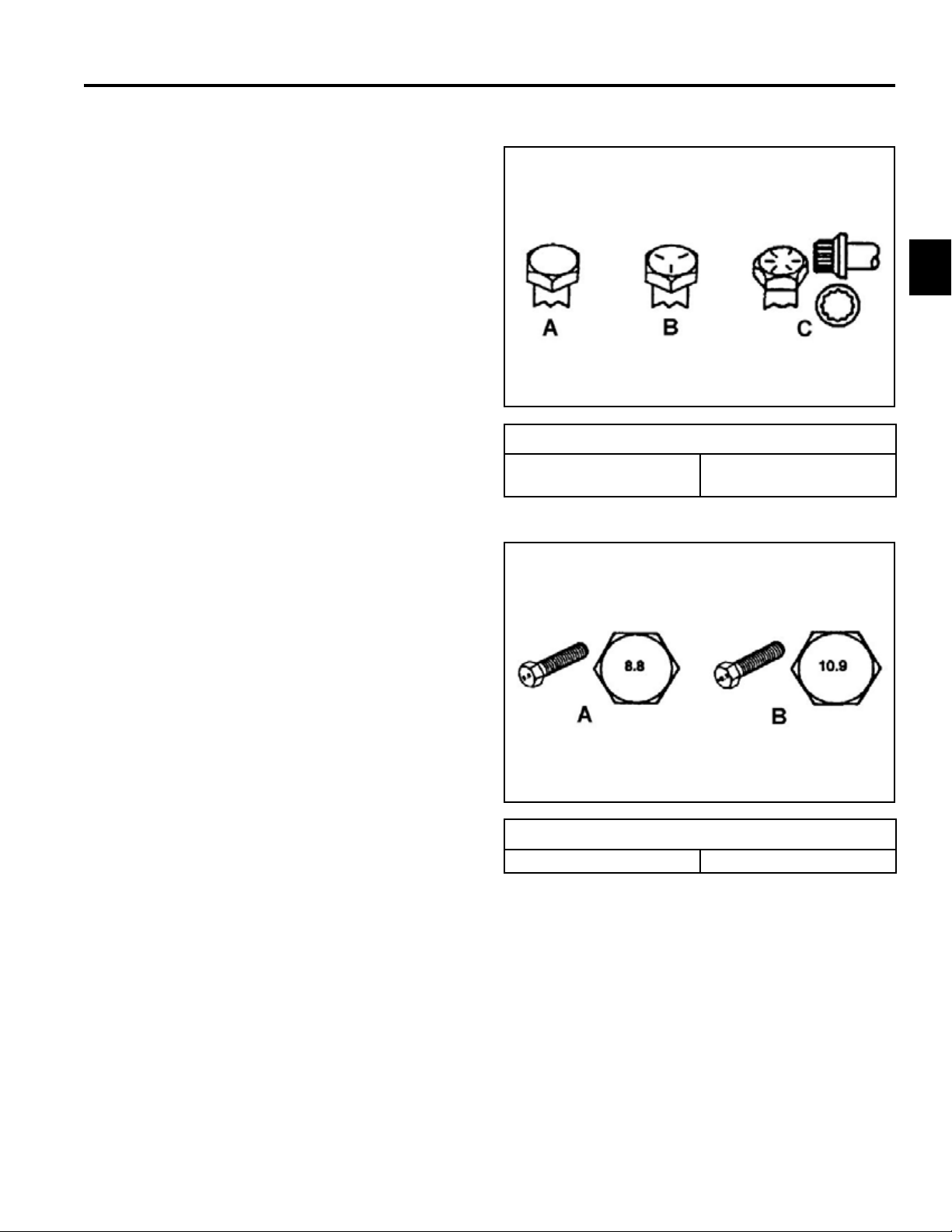
Fastener Identication
Inch Series bolts and Screws
(A) Grade 1 & 2
(B) Grade 5
2
(C) Grade 8
The standard method of verifying torque shall be performed by marking a line on the fastener (head or nut)
and mating part, then back off fastener 1/4 of a turn.
Measure the torque required to tighten the fastener until
the lines match up.
Metric Bolts and Screws
(A) Class 8.8 (B) Class 10.9
Toro 30” Aerator Service Manual
2-1
Page 12

SPECIFICATIONS & MAINTENANCE
Standard Torque for Dry, Zinc Plated, and Steel Fasteners (Inch Series)
Standard Torque for Dry, Zinc Plated & Steel Fasteners (Inch Series)
Grade 1, 5, &
Thread Size
2
# 6 - 32 UNC
# 6 - 40 UNF 17 ± 2 190 ± 20 25 ± 2 280 ± 20
# 8 - 32 UNC
# 8 - 36 UNF 31 ± 3 350 ± 30 43 ± 4 31 ± 3
# 10 - 24 UNC
#10 - 32 UNF 48 ± 4 540 ± 45 68 ± 6 765 ± 70
1/4 - 20 UNC 48 ± 7 53 ± 7 599 ± 79 100 ± 10 1125 ± 100 140 ± 15 1580 ± 170
1/4 - 28 UNF 53 ± 7 65 ± 10 734 ± 113 115 ± 10 1300 ± 100 160 ± 15 1800 ± 170
5/16 - 18 UNC 115 ± 15 105 ± 15 1186 ± 169 200 ± 25 2250 ± 280 300 ± 30 3390 ± 340
5/16 - 24 UNF 138 ± 17 128 ± 17 1446 ± 192 225 ± 25 2540 ± 280 325 ± 30 3670 ± 340
3/8 - 16 UNC 16 ± 2 16 ± 2 22 ± 3 30 ± 3 41 ± 4 43 ± 4 58 ± 5
3/8 - 24 UNF 17 ± 2 18 ± 2 24 ± 3 35 ± 3 47 ± 4 50 ± 4 68 ± 5
7/16 - 14 UNC 27 ± 3 27 ± 3 37 ± 4 50 ± 5 68 ± 7 70 ± 7 68 ± 9
7/16 - 20 UNF 29 ± 3 29 ± 3 39 ± 4 55 ± 5 75 ± 7 77 ± 7 104 ± 9
1/2 - 13 UNC 30 ± 3 48 ± 7 65 ± 9 75 ± 8 102 ± 11 105 ± 10 142 ± 14
1/2 - 20 UNF 32 ± 3 53 ± 7 72 ± 9 85 ± 8 115 ± 11 120 ± 10 163 ± 14
5/8 - 11 UNC 65 ± 10 88 ± 12 119 ± 16 150 ± 15 203 ± 20 210 ± 20 285 ± 27
5/8 - 18 UNF 75 ± 10 95 ± 15 129 ± 20 170 ± 15 230 ± 20 240 ± 20 325 ± 27
3/4 - 10 UNC 93 ± 12 140 ± 20 190 ± 27 265 ± 25 359 ± 34 374 ± 35 508 ± 47
3/4 - 16 UNF 115 ± 15 165 ± 25 224 ± 34 300 ± 25 407 ± 34 420 ± 35 569 ± 47
7/8 - 9 UNC 140 ± 20 225 ± 25 305 ± 34 430 ± 45 583 ± 61 600 ± 60 813 ± 81
7/8 - 14 UNF 155 ± 25 260 ± 30 353 ± 41 475 ± 45 644 ± 61 660 ± 60 895 ± 81
8 with Thin
Height Nuts
In-lb In-lb N-cm In-lb N-cm In-lb N-cm
10 ± 2 13 ± 2 147 ± 23
13 ± 2 25 ± 5 282 ± 30
18 ± 2 30 ± 5 339 ± 56
ft-lb ft-lb N-m ft-lb N-m ft-lb N-m
SAE Grade 1 Bolts, Screws,
Studs, & Sems with Regular
Height Nuts (SAE J995
Grade 2 or Stronger Nuts)
SAE Grade 5 Bolts, Screws,
Studs, & Sems with Regular
Height Nuts (SAE J995
Grade 2 or Stronger Nuts)
15 ± 2 169 ± 23 23 ± 2 260 ± 34
29 ± 3 330 ± 30 41 ± 4 460 ± 45
42 ± 4 475 ± 45 60 ± 6 674 ± 70
SAE Grade 8 Bolts, Screws,
Studs, & Sems with Regular
Height Nuts (SAE J995
Grade 2 or Stronger Nuts)
Note: Reduce torque values listed in the table above
by 25% for lubricated fasteners. Lubricated fasteners
are defined as threads coated with a lubricant such as
oil, graphite, or thread sealant such as Loctite.
Note: Torque values may have to be reduced when
installing fasteners into threaded aluminum or brass.
The specific torque value should be determined based
on the fastener size, the aluminum or base material
strength, length of thread engagement, etc.
2-2
Toro 30” Aerator Service Manual
Note: The nominal torque values listed above for
Grade 5 and 8 fasteners are based on 75% of the
minimum proof load specified in SAE J429. The
tolerance is approximately ± 10% of the nominal torque
value. Thin height nuts include jam nuts.
Page 13

SPECIFICATIONS & MAINTENANCE
Standard Torque for Dry, Zinc, and Steel Fasteners (Metric Fasteners)
Standard Torque for Dry, Zinc & Steel Fasteners (Metric Fasteners)
Class 8.8 Bolts, Screws, and Studs with
Thread Size
M5 X 0.8 57 ± 5 in-lb 644 ± 68 N-cm 78 ± 8 in-lb 881 ± 90 N-cm
M6 X 1.0 96 ± 10 in-lb 1085 ± 113 N-cm 133 ± 14 in-lb 1503 ± 158 N-cm
M8 X 1.25 19 ± 2 ft-lb 26 ± 3 N-m 28 ± 3 ft-lb 38 ± 4 N-m
M10 X 1.5 38 ± 4 ft-lb 52 ± 5 N-m 54 ± 6 ft-lb 73 ± 8 N-m
M12 X 1.75 66 ± 7 ft-lb 90 ± 10 N-m 93 ± 10 ft-lb 126 ± 14 N-m
M16 X 2.0 166 ± 15 ft-lb 225 ± 23 N-m 229 ± 23 ft-lb 310 ± 31 N-m
M20 X 2.5 325 ± 33 ft-lb 440 ± 45 N-m 450 ± 36 ft-lb 610 ± 62 N-m
Note: Reduce torque values listed in the table above
by 25% for lubricated fasteners. Lubricated fasteners
are defined as threads coated with a lubricant such as
oil, graphite, or thread sealant such as Loctite.
Note: Torque values may have to be reduced when
installing fasteners into threaded aluminum or brass.
The specific torque value should be determined based
on the fastener size, the aluminum or base material
strength, length of thread engagement, etc.
Regular Height Nuts
(Class 8 or Strong Nuts)
Note: The nominal torque values listed above are
based on 75% of the minimum proof load specified in
SAE J1199. The tolerance is approximately ± 10% of
the nominal torque value. Thin height nuts include jam
nuts.
Class 10.9 Bolts, Screws, and Studs with
Regular Height Nuts (
Class 10 or Strong Nuts)
2
Toro 30” Aerator Service Manual
2-3
Page 14

2
SPECIFICATIONS & MAINTENANCE
30” Aerator Specications
30” Stand-On Aerator
Models: 23518 / 33518
Engines: 36.8 cu-in. (603cm³)
Make Kawasaki
Model FS481 V-Twin
Hi-Idle 3600 RPM
Low-Idle 1250-1550 RPM
Spark Plug BPR4ES (NKG)
Spark Plug Gap .030"/.76mm
Oil SAE 10W-30
Oil Capacity 1.8 Qt. (1.7 liters)
Starter Electric Only
Fuel Tank Volume 5.0 US gal (18.9 L)
Power System:
Transmission Hydro-Gear ZT3400
Hydraulic Fluid Toro Hydro Oil
Hydraulic Fluid
Capacity
Ground Speed
(fwd/rev)
Drive Tires
(pneumatic)
Tire Pressure 12-14 psi (83-97 kPa)
70.3 oz.(2.0 L) w/lter
7.5 mph/NA
16 x 6.50 - 8
Dimensional:
Width (in/cm) 47.75/121.3
Length Operating
(in/cm)
Length Handle
Stored (in/cm)
Height Operating
(in/cm)
Height Handle
Stored (in/cm)
Weight (lb/kg) 1015.0/460.0
Max Operating
Depth (in/cm)
Plugs per Sq-ft./
Sq-meter
2-4
64.0/162.6
52.0/132.1
4.0/10.2
4.6/49.5
N/A
N/A
Toro 30” Aerator Service Manual
Page 15

SPECIFICATIONS & MAINTENANCE
Recommended Maintenance Schedule
Maintenance Service Interval Maintenance Procedure
After the rst 5 hours • Change the engine oil.
After the rst 100 hours
Before each use or daily
Every 25 hours
Every 50 hours
Every 80 hours • Remove engine shrouds and clean cooling ns.
Every 100 hours • Change the engine oil. (May need more often under severe conditions.)
Every 160 hours • Check the spark plugs.
Every 250 hours
Every 500 hours
Monthly • Check the battery charge.
Yearly
Yearly or before storage • Touch up chipped paint
• Change the auxiliary hydraulic reservoir lter and uid.
• Change the hydraulic transmission lter and uid.
• Check the engine oil level.
• Check the safety interlock system.
• Check for loose hardware.
• Lubricate the chains.
• Check the condition and tension of the chains.
• Check the condition of the sprockets.
• Check the tines.
• Clean the engine and exhaust system area.
• Clean the grass and debris build-up from the machine.
• Grease the jackshaft bearings.
• Grease the wheel bearings.
• Grease the tine shaft bearings.
• Grease the tine assembly idlers.
• Grease the control pivots.
• Check spark arrester (if equipped).
• Check the tire pressures.
• Check the condition and tension of the belts.
• Check the auxiliary hydraulic oil level.
• Check the hydraulic transmission oil level.
• Replace the primary air cleaner element - check secondary air cleaner element;
replace if dirty. (May need more often under severe conditions. See the Engine
manual for additional information.)
• Change the auxiliary hydraulic reservoir lter and uid.
• Change the hydraulic transmission lter and uid.
• Replace the secondary air cleaner element. (May need more often under severe
conditions. See the Engine manual for additional information.)
• Grease the front caster pivots.
• Grease the belt idler pivot.
• Lubricate the caster wheel hubs.
• Check the torque of the wheel hub nuts.
• Check the torque on the wheel lug nuts.
• Check the transmission output shaft nut torque specication.
2
Toro 30” Aerator Service Manual
2-5
Page 16
SPECIFICATIONS & MAINTENANCE
2
Premaintenance Procedures
Note: Shut off engine, wait for all moving parts to
stop, engage parking brake, and remove key
before servicing, cleaning, or making any
adjustments to the unit.
Caution
Raising the unit for service or maintenance
relying solely on mechanical or hydraulic
jacks could be dangerous. The mechanical or
hydraulic jacks may not be enough support or
may malfunction allowing the unit to fall, which
could cause injury.
Do not rely solely on mechanical or hydraulic
jacks for support. Use adequate jack stands or
equivalent support.
Lubrication
Lubricate Chains
Service Interval: Before each use or daily
Important: Do not lubricate chains with penetrating
oil or solvents. Use oil or chain lubricant.
1. Stop engine, wait for all moving parts to stop, and
remove key. Engage parking brake.
2. Lift the rear of the unit and support using jack stands
or equivalent support.
Caution
Raising the unit for service or maintenance
relying solely on mechanical or hydraulic
jacks could be dangerous. The mechanical or
hydraulic jacks may not be enough support or
may malfunction allowing the unit to fall, which
could cause injury.
Do not rely solely on mechanical or hydraulic
jacks for support. Use adequate jack stands or
equivalent support.
3. Start engine and move throttle control ahead to 1/2
throttle position. Disengage parking brake.
Warning
Engine must be running and drive wheels must
be turning so adjustments can be performed.
Contact with moving parts or hot surfaces may
cause personal injury.
Keep ngers, hands, and clothing clear of
rotating components and hot surfaces.
4. With the engine running, slowly move the motion
control levers forward and lubricate all six chains.
5. Check the condition and tension of the chains.
!!
2-6
Toro 30” Aerator Service Manual
Page 17

Lubricate Grease Fittings
SPECIFICATIONS & MAINTENANCE
Note: See chart for service intervals.
1. Stop engine, wait for all moving parts to stop, and
remove key. Engage parking brake.
2. Lubricate ttings with NGLI grade #2 multi-purpose
gun grease.
Refer to the following chart for tting locations and
lubrication schedule.
Lubrication Chart
Fitting
Locations
A. Front Caster
Pivots
B. Jackshaft
Bearings
C. Wheel
Bearings
D. Tine Shaft
Bearings
E. Tine
Assembly Idlers
F. Control
Pivots
G. Belt Idler
Pivot
H. Front Caster
Hubs
Initial
Pumps
*0 2 Yearly
1 8 25 hours
1 2 25 hours
1 4 25 hours
1 2 25 hours
1 4 50 hours
1 1 Yearly
*0 2
Number
of Places
Service
Interval
Yearly
A B
C
D
H
G
Fig. 001 g. 13a G020222
* Seestep3forspeciallubricationinstructionsonthefront
casterpivots.
3. Lubricate front caster pivots once a year. Remove
hex plug and cap. Thread grease tting in hole
and pump with grease until it oozes out around top
bearing. Remove grease tting and thread plug back
in. Place cap back on.
F
E
2
Toro 30” Aerator Service Manual
2-7
Page 18

SPECIFICATIONS & MAINTENANCE
2
Lubricate Caster Wheel Hubs
Service Interval: Yearly
1. Stop engine, wait for all moving parts to stop, and
remove key. Engage parking brake.
2. Remove caster wheel from caster forks.
3. Remove seal guards from the wheel hub (Fig. 002).
4. Remove one of the spacer nuts from the axle
assembly in the caster wheel (Fig. 002). Note that
thread locking adhesive has been applied to lock the
spacer nuts to the axle. Remove the axle (with the
other spacer nut still assembled to it) from the wheel
assembly.
5. Pry out seals, and inspect bearings for wear or
damage and replace if necessary.
6. Pack the bearings with a NGLI grade #1 multipurpose grease.
7. Insert one bearing, one new seal into the wheel.
Note: Replace the seals.
8. If the axle assembly has had both spacer nuts
removed (or broken loose), apply a thread locking
adhesive to one spacer nut and thread onto the
axle with the wrench ats facing outward. Do not
thread spacer nut all of the way onto the end of
the axle. Leave approximately 3mm (1/8”) from the
outer surface of the spacer nut to the end of the axle
inside the nut.
9. Insert the assembled nut and axle into the wheel on
the side of the wheel with the new seal and bearing.
10. With the open end of the wheel facing up, ll the
area inside the wheel around the axle full of NGLI
grade #1 multi-purpose grease.
A
B
Fig. 002 g. 14 G006115
A. Seal guard B. Spacer nut w/wrench ats
11. Insert the second bearing and new seal into the
wheel.
12. Apply a thread locking adhesive to the 2nd spacer
nut and thread onto the axle with the wrench ats
facing outward.
13. Torque the nut to 75-80 in-lbs. (8-9 Nm), loosen,
then re-torque to 20-25 in-lbs. (2-3 Nm). Make sure
axle does not extend beyond either nut.
14. Reinstall the seal guards over the wheel hub and
insert wheel into caster fork. Reinstall caster bolt and
tighten nut fully.
Important: To prevent seal and bearing damage,
check the bearing adjustment often. Spin the
caster tire. The tire should not spin freely
(more than 1 or 2 revolutions) or have any side
play. If the wheel spins freely, adjust torque on
spacer nut until there is a slight amount of drag.
Reapply thread locking adhesive.
2-8
Toro 30” Aerator Service Manual
Page 19

SPECIFICATIONS & MAINTENANCE
Engine Maintenance
Service Air Cleaner
Service Interval: Every 250 hours - Replace the primary
air cleaner element - check secondary air cleaner
element; replace if dirty. (May need more often
under severe conditions. See the Engine Owner’s
Manual for additional information.)
Every 500 hours - Replace the secondary air cleaner
element. (May need more often under severe conditions. See the Engine Owner’s Manual for additional
information.)
1. Stop engine, wait for all moving parts to stop, and
remove key. Engage parking brake.
2. See the Engine Owner’s Manual for maintenance
instructions.
Change Engine Oil
Service Interval: After the rst 5 hours
5. Clean around oil ll cap and remove cap. Fill to
specied capacity and replace cap.
6. Add 1.8 qt. (1.7 L) of Toro Premium Oil. Do not
overll. Start the engine and check for leaks. Stop
engine and recheck oil level.
7. Wipe up any spilled oil from engine deck mounting
surfaces.
Check Spark Plugs
Service Interval: Every 160 hours
Remove spark plugs, check condition and reset gaps,
or replace with new plugs. See the Engine Owner’s
Manual.
Check Spark Arrester (if equipped)
Service Interval: Every 50 hours
! !
Warning
2
Every 100 hours (May need more often under
severe conditions.)
1. Stop engine, wait for all moving parts to stop, and
remove key. Engage parking brake.
2. Drain oil while engine is warm from operation.
3. The oil drain hose assembly is located on the left
side of the engine.
Place pan under machine to catch oil. Remove oil
drain plug. Allow oil to drain and replace oil drain
plug. Torque plug to 20-24 ft-lbs. (27-33 Nm).
4. Replace the oil lter per the Engine Owner’s Manual.
Clean around the oil lter and carefully remove the
lter by unscrewing it. Make sure no oil drains onto
the belt drives through the holes in the engine deck.
Before the new lter is installed, apply a thin coating
of Toro 4–Cycle Premium Engine Oil on the surface
of the rubber seal. Turn lter clockwise until rubber
seal contacts the lter adapter, then tighten lter an
additional 2/3 to 3/4 turn.
Hot exhaust system components may ignite
gasoline vapors even after the engine is
stopped. Hot particles exhausted during engine
operation may ignite ammable materials.
Fire may result in personal injury or property
damage.
Do not refuel or run engine unless spark arrester
is installed.
1. Stop engine, wait for all moving parts to stop, and
remove key. Engage parking brake.
2. Wait for mufer to cool.
3. If any breaks in the screen or welds are observed,
replace arrester.
4. If plugging of the screen is observed, remove
arrester and shake loose particles out of the arrester
and clean screen with a wire brush (soak in solvent if
necessary). Reinstall arrester on exhaust outlet.
Toro 30” Aerator Service Manual
2-9
Page 20

SPECIFICATIONS & MAINTENANCE
2
Fuel System Maintenance
Change Fuel Filter
A fuel lter is installed in the fuel line between the fuel
tank and the engine. Replace when necessary.
Note: It is important to reinstall the fuel line
hoses and secure in place, the same way as
originally installed at the factory, to keep the
fuel line away from components.
Electrical System Maintenance
Check Battery Charge
Service Interval: Monthly
Warning
CALIFORNIA
Proposition 65 Warning
Battery posts, terminals, and related
accessories contain lead and lead compounds,
chemicals known to the State of California to
cause cancer and reproductive harm.
Wash hands after handling.
Allowing batteries to stand for an extended period of
time without recharging them will result in reduced
performance and service life. To preserve optimum
battery performance and life, recharge batteries in
storage when the open circuit voltage drops to 12.4
volts.
!!
Note: To prevent damage due to freezing, battery
should be fully charged before putting away
for winter storage.
Check the voltage of the battery with a digital voltmeter.
Locate the voltage reading of the battery in the table and
charge the battery for the recommended time interval
to bring the charge up to a full charge of 12.6 volts or
greater.
Important: Make sure the negative battery cable
is disconnected and the battery charger used
for charging the battery has an output of 16
volts and 7 amps or less to avoid damaging the
battery.
2-10
Toro 30” Aerator Service Manual
Page 21

SPECIFICATIONS & MAINTENANCE
Drive System Maintenance
Check Tire Pressures
Service Interval: Every 50 hours
1. Stop engine, wait for all moving parts to stop, and
remove key. Engage parking brake.
2. Check tire pressure in drive tires.
3. Inate drive tires to 12-14 psi (83-97 kPa).
4. Semi-pneumatic caster tires do not need to be
inated.
Check Wheel Hub Nuts Torque Specication
Service Interval: Yearly
Torque the wheel hub nuts to 210-260 ft-lbs. (285-350
Nm).
Note: Do not use anti-seize compound on the wheel
hub.
Check Wheel Lug Nuts Torque Specication
Check Condition Of Chains
Service Interval: Before each use or daily
1. Stop engine, wait for all moving parts to stop, and
remove key. Engage parking brake.
2. Check the chains on both sides of the unit for proper
tension. The chains should be able to move up and
down 1/4”-1/2” (6-12mm).
3. If chains pop or snap see “Jackshaft Drive Chain
Tension Adjustment” on page 2-12, “Drive Wheel
Chain Tension Adjustment” on page 2-13, or “Tine
Drive Chain Adjustment” on page 2-18.
Check Condition Of Sprockets
Service Interval: Before each use or daily
1. Stop engine, wait for all moving parts to stop, and
remove key. Engage parking brake.
2. Inspect sprockets for wear and replace as required.
Check Transmission Output Shaft Nut
Torque Specication
2
Service Interval: Yearly
Torque the wheel lug nuts to 90-95 ft-lbs. (122-129 Nm).
Service Interval: Yearly
Torque the nut on the transmission output tapered shaft
to 210-260 ft-lbs. (285-353 Nm).
Toro 30” Aerator Service Manual
2-11
Page 22
SPECIFICATIONS & MAINTENANCE
2
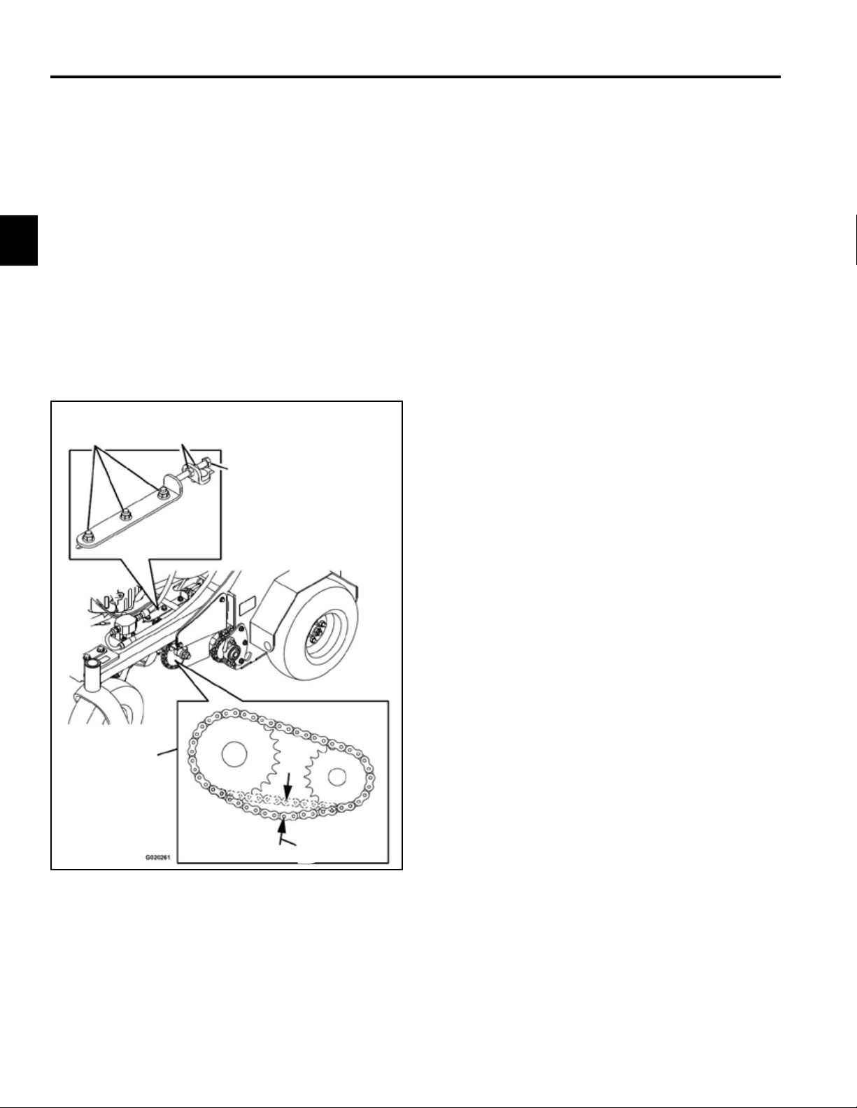
Jackshaft Drive Chain Tension Adjustment
1. Stop engine, wait for all moving parts to stop, and
remove key. Engage parking brake.
2. Lift the rear of the unit and support using jack stands
or equivalent support.
3. Check the chains on both sides of the unit for proper
tension. The chains should be able to move up and
down 6-12mm (1/4”-1/2”).
4. Loosen the nuts on the three hydro mounting bolts
and the two on the adjustment bolt as shown in
Figure 003. The nuts on the hydro mounting bolts
must be loosened on both sides of the unit (Fig.
003).
A
B
C
5. Turn the adjustment bolt to move transmission
adjustment plates and hydros. Tighten the nuts on
both sides of the adjustment bolts when the chains
are properly tensioned.
6. Tighten hydro mounting bolts.
7. Adjust motion controls as stated in the “Motion
Control Linkage Adjustment” section of this chapter.
E
D
Fig. 003 g. 16 G020261
A. Hydro mounting bolts D. 6-12mm (1/4-1/2”)
& nuts E. Guard removed for
B. Nuts clarity
C. Adjustment bolt
2-12
Toro 30” Aerator Service Manual
Page 23
SPECIFICATIONS & MAINTENANCE
Drive Wheel Chain Tension Adjustment
1. Stop engine, wait for all moving parts to stop, and
remove key. Engage parking brake.
2. Lift the rear of the unit and support using jack stands
or equivalent support.
3. Check the chains on both sides of the unit for proper
tension. The chains should be able to move up and
down 1/4”-1/2” (6-12mm).
4. Adjust the idler sprockets.
5. Recheck the chain tension and tighten the idler bolt.
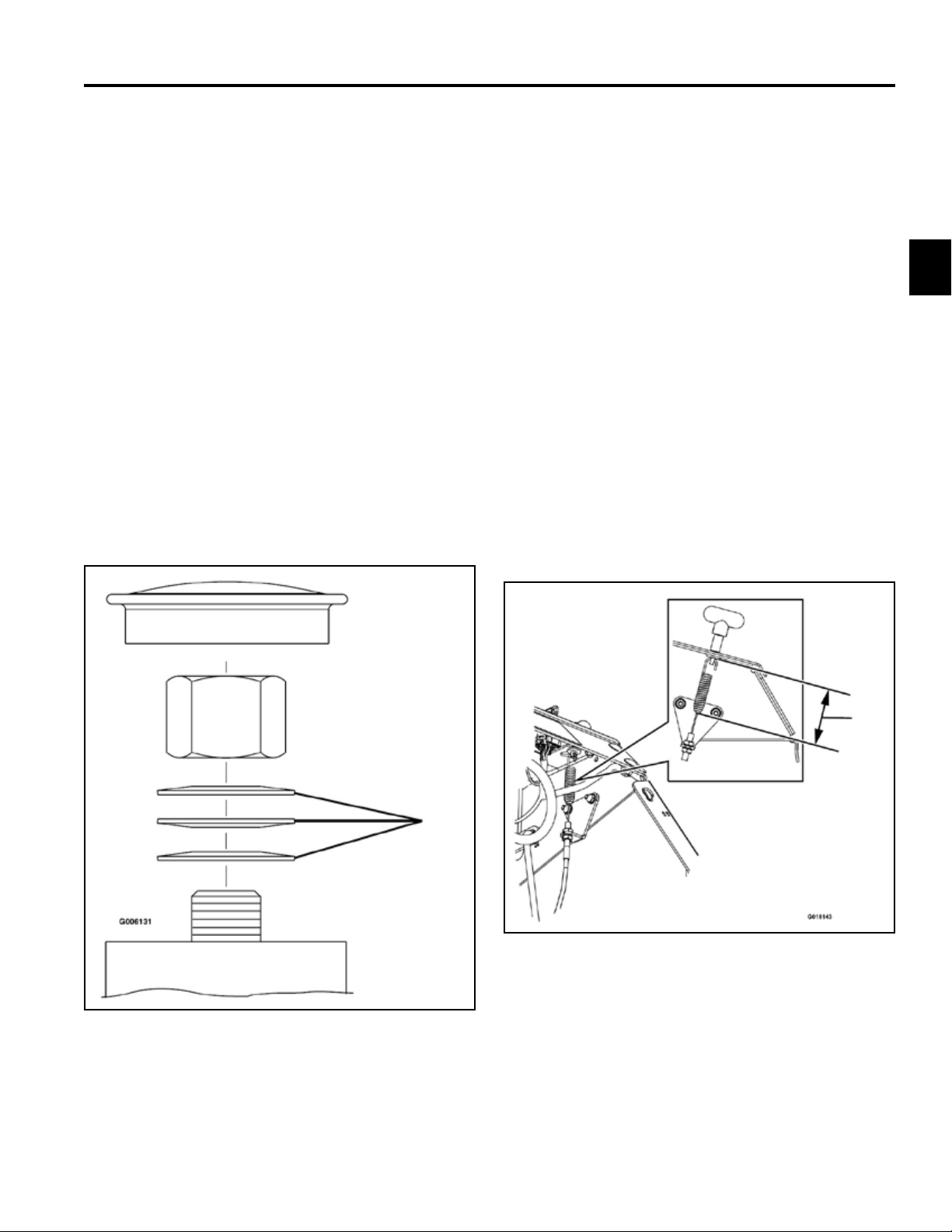
Caster Pivot Bearings Pre-Load Adjustment
Remove dust cap from caster and tighten nyloc nut until
washers are at and back off 1/4 of a turn to properly
set the pre-load on the bearings. If disassembled, make
sure the spring disc washers are reinstalled as shown in
Figure 004.
Brake Maintenance
Adjusting the Parking Brake
If the parking brake does not hold securely, an
adjustment is required.
1. Park the machine on a level surface.
2
2. Shut off engine and wait for all moving parts to stop.
3. Check the air pressure in the drive tires. If needed,
adjust to the recommended ination.
4. Disengage the parking brake.
5. Loosen the adjustment nut on the brake cable under
the console.
6. Engage the parking brake.
7. Adjust the nut position until 3-1/8” (7.9cm) from the
bottom of the link to the bottom of the spring (Fig.
005).
A
Fig. 004 g. 17 G006131
A. Spring disc washers
A
Fig. 005 g. 18 G018143
A. 3-1/8” (7.9cm)
8. Tighten the cable adjustment nuts.
9. Check the parking brake; repeat steps 5 through 8 if
necessary.
Toro 30” Aerator Service Manual
2-13
Page 24

SPECIFICATIONS & MAINTENANCE
2
Adjusting the Brake Switch
1. Park the machine on a level surface.
2. Shut off the engine and wait for all moving parts to
stop.
3. Prior the adjusting the brake switch ensure the
parking brake is properly adjusted. See “Adjusting
the Parking Brake” on page 3-13.
4. Engage the parking brake.
5. Check the distance from the parking brake switch
bracket to the hydro brake arm. The distance should
be 1/8” (3.2mm) (Fig. 006).
Belt Maintenance
Check Condition & Tension Of Belts
Service Interval: Every 50 hours
1. Stop engine, wait for all moving parts to stop, and
remove key. Engage parking brake.
2. Lift the front of the unit and support using jack
stands or equivalent support.
3. Check the auxiliary pump drive belt condition and
tension; belt should be snug. See Auxiliary Pump
Drive Belt Adjustment in this section.
4. Check condition of the transmission drive belt.
Transmission Drive Belt Tension
Note: No adjustments are required for belt tension.
1. Stop engine, wait for all moving parts to stop, and
remove key. Engage parking brake.
Fig. 006 g. 19 G018137
A. Parking brake switch bracket
B. 1/8” (3.2mm) gap
6. If adjustment is required, loosen the bolt holding the
parking brake switch bracket and adjust the distance
between the parking brake switch bracket and the
hydro brake arm to be 1/8” (3.2mm).
2. Install the new belt.
3. Make sure the idler arm and pulley can move freely.
Auxiliary Pump Drive Belt Adjustment
1. Stop engine, wait for all moving parts to stop, and
remove key. Engage parking brake.
2. To tighten belt, loosen the 3/8” nyloc nut on auxiliary
pump belt idler pulley. Slide bolt inward in slot and
retighten nyloc nut.
3. When properly adjusted, the belt should have 1/2”
(1.3cm) of deection with 3 pounds of pressure on
the belt midway between the auxiliary pump and
engine pulley.
7. Tighten the bolt holding the parking brake bracket.
2-14
Toro 30” Aerator Service Manual
Page 25

SPECIFICATIONS & MAINTENANCE
Controls System Maintenance
Motion Control Linkage Adjustment
1. Park the machine on a level surface.
2. Shut off engine and wait for all moving parts to stop.
3. Push the control levers all the way forward to the
front reference bar.
• If the control levers contact the reference bar,
allow the control levers to return to neutral.
Remove the spring clevis pin on the turnbuckle of
the motion control linkage. Rotate the turnbuckle
counterclockwise (as viewed from the top of the
machine). Reinstall the spring clevis pin and
move the control lever forward (Fig. 007). Repeat
this step until there is a gap between the control
lever and the front reference bar. Once the gap is
achieved, proceed with step 4.
• If the control levers do not contact the reference
bar, then proceed to step 4.
4. Allow the control levers to return to neutral. Remove
the spring clevis pin on the turnbuckle of the motion
control linkage. Rotate the turnbuckle clockwise (as
viewed from the top of the machine). Reinstall the
spring clevis pin and move the control lever forward.
Repeat this step until there is minimal gap or contact
between the control lever and the front reference
bar.
2
5. Remove the spring clevis pin, rotate the turnbuckle
clockwise one more full turn.
6. Reinstall the spring clevis pin. Rotate locknut against
the turnbuckle.
7. Repeat steps 3 through 6 for other motion control
linkage.
B
C
A
Fig. 007 g. 20 G020223
A. Spring clevis pin C. Turnbuckle
B. Locknut
Toro 30” Aerator Service Manual
2-15
Page 26

SPECIFICATIONS & MAINTENANCE
2
Hydraulic System Maintenance
Check Auxiliary Hydraulic Oil Level
Service Interval: Every 50 hours
1. Lower the tines to the ground.
2. Stop engine and wait for all moving parts to stop,
and remove key. Engage parking brake.
3. Clean area around hydraulic reservoir cap and
remove cap. Oil level should be to the top of the
bafe inside the tank. If not, add oil. Use Toro Hydro
Oil. Replace hydraulic reservoir cap and tighten until
snug. Do not over-tighten.
Note: The bafe is labeled Hot and Cold. The oil
level varies with the temperature of the oil.
The Hot level shows the level of oil when it
is at 107°C (225°F). The Cold level shows the
level of the oil when it is at 24°C (75°F). Fill
to the appropriate level depending upon the
temperature of the oil. For example: If the oil
is about 65°C (150°F), ll to halfway between
the Hot and Cold levels. If the oil is at room
temperature (about 24°C (75°F)), ll only to
the Cold level.
Check Hydraulic Transmission Oil Level
Change Auxiliary Hydraulic Reservoir Fluid and Filter
Service Interval: After the rst 100 hours
Every 250 hours thereafter
1. Stop engine, wait for all moving parts to stop, and
remove key or spark plug wire(s). Engage parking
brake.
2. Carefully clean area around the front of the auxiliary
pump and ll cap; also clean around the lter. It
is important that no dirt or contamination enter
hydraulic system.
3. Unscrew the suction hose from the pump tting,
clean around the pump tting, and allow oil to drain.
4. Unscrew the lter to remove and allow oil to drain.
Important: Apply a thin coat of oil on the surface of
the rubber seal.
Turn lter clockwise until rubber seal contacts the
lter adapter, then tighten the lter an additional 2/3
to 3/4 turn.
5. Reinstall the hose and torque to 50 Nm (37 ft-lbs.).
6. Add Toro Hydro Oil until the level reaches the cold
ll line located on the reservoir tank. Start engine
and raise and lower the tines. Lower the tines to the
ground and rell the reservoir to the cold ll line.
Service Interval: Every 50 hours
1. Stop engine and wait for all moving parts to stop,
and remove key. Engage parking brake.
2. With the unit cold, check the expansion tank and if
necessary add Toro Hydro Oil to the Full Cold line.
2-16
Toro 30” Aerator Service Manual
Page 27

SPECIFICATIONS & MAINTENANCE
Change Hydraulic Transmission Filters and Fluid
Service Interval: After the rst 100 hours
Every 250 hours thereafter
1. Stop engine, wait for all moving parts to stop, and
remove key or spark plug wire(s). Engage parking
brake.
2. Locate the two lters under the transmissions.
Remove lter guards.
3. Carefully clean area around lters. It is important
that no dirt or contamination enter hydraulic system.
4. Unscrew lters to remove and allow oil to drain from
drive system.
Important: Before reinstalling new lters, apply
a thin coat of Toro Premium Hydro Oil on the
surface of the lters rubber seal.
Turn the lters clockwise until rubber seal contacts
the lter adapter then tighten the lter an additional
3/4 to 1 full turn.
5. Remove the vent plug on each transmission and ll
through expansion reservoir, when oil comes out of
vent reinstall plug.
Toro Premium Hydro Oil is recommended. Refer to
the chart for an acceptable alternative:
Caution
Raising the unit for service or maintenance
relying solely on mechanical or hydraulic
jacks could be dangerous. The mechanical or
hydraulic jacks may not be enough support or
may malfunction allowing the unit to fall, which
could cause injury.
Do not rely solely on mechanical or hydraulic
jacks for support. Use adequate jack stands or
equivalent support.
7. Start engine and move throttle control ahead to 1/2
throttle position. Disengage parking brake.
Warning
Engine must be running and drive wheels must
be turning so motion control adjustment can
be performed. Contact with moving parts or hot
surfaces may cause personal injury.
Keep ngers, hands, and clothing clear of
rotating components and hot surfaces.
A. With the engine running, slowly move the
directional control in both forward and reverse
directions (5 to 6 times). Check the oil level, and
add oil as required after stopping the engine.
!!
2
Hydro Oil Change Interval
Toro Premium Hydro Oil
(Preferred)
Mobil 1 15W50 250 Hours
Torque plugs to 20 Nm (180 in-lbs.). Continue to add
Toro Premium Hydro Oil until it reaches the full cold
line on the expansion reservoir.
6. Raise the rear of machine up and support with jack
stands (or equivalent support) just high enough to
allow drive wheels to turn freely.
Toro 30” Aerator Service Manual
500 Hours
B. It may be necessary to repeat step A until all the
air is completely purged from the system. When
the transaxle operates at normal noise levels and
moves smoothly forward and reverse at normal
speeds, then the transaxle is considered purged.
Note: Do not change the hydraulic system oil
(except for what can be drained when
changing lter), unless it is felt the oil has
been contaminated or been extremely
hot. Changing oil unnecessarily could
damage hydraulic system by introducing
contaminants into the system.
2-17
Page 28

2
SPECIFICATIONS & MAINTENANCE
Tine Maintenance
Check Tines
Service Interval: Before each use or daily
1. Stop engine, wait for all moving parts to stop, and
remove key. Engage parking brake.
2. Lift the rear of the unit and support using jack stands
or equivalent support.
Caution
Raising the unit for service or maintenance
relying solely on mechanical or hydraulic
jacks could be dangerous. The mechanical or
hydraulic jacks may not be enough support or
may malfunction allowing the unit to fall, which
could cause injury.
Do not rely solely on mechanical or hydraulic
jacks for support. Use adequate jack stands or
equivalent support.
3. Remove and retain the two bolts from the rear cover
panel.
4. Remove rocks and other debris from the tines.
5. Inspect the tines and replace as required.
Tine Drive Chain Adjustment
1. Stop engine, wait for all moving parts to stop, and
remove key. Engage parking brake.
2. Lift the rear of the unit and support using jack stands
or equivalent support.
3. Check the chains on both sides of the unit for proper
tension. The chains should be able to move up and
down 1/4-1/2” (6-12mm).
4. Adjust the idler sprocket.
5. Recheck the chain tension and tighten the idler bolt.
2-18
Toro 30” Aerator Service Manual
Page 29

Chassis
Exploded View - Mainframe
(Fig. 008)
H
F
CHASSIS
E
D
K
3
J
I
H
B
A
G
C
1
Fig. 008 subsystem mainframe_smr
A. Main frame assembly E. Mufer guard I. Plate, serial no. (1x2.88)
B. Front caster assembly F. Guard - chain, RH J. Tube, manual
C. Weight G. Guard - chain, LH K. Platform assembly
D. Access cover H. Plate, serial no. (1x5)
1 Bolt installed from the bottom in this location only.
Toro 30” Aerator Service Manual
3-1
Page 30

CHASSIS
3
Lubricate Caster Wheel Hubs
1. Stop engine, wait for all moving parts to stop, and
remove key. Engage parking brake.
2. Remove caster wheel from caster forks.
3. Remove seal guards from the wheel hub (Fig. 009).
A
B
Fig. 009 g. 14 G006115
A. Seal guard
B. Spacer nut with wrench ats
4. Remove one of the spacer nuts from the axle
assembly in the caster wheel. Note that thread
locking adhesive has been applied to lock the spacer
nuts to the axle. Remove the axle (with the other
spacer nut still assembled to it) from the wheel
assembly.
5. Pry out seals, and inspect bearings for wear or
damage and replace if necessary.
8. If the axle assembly has had both spacer nuts
removed (or broken loose), apply a thread locking
adhesive to one spacer nut and thread onto the
axle with the wrench ats facing outward. Do not
thread spacer nut all of the way onto the end of
the axle. Leave approximately 3mm (1/8”) from the
outer surface of the spacer nut to the end of the axle
inside the nut.
9. Insert the assembled nut and axle into the wheel on
the side of the wheel with the new seal and bearing.
10. With the open end of the wheel facing up, ll the
area inside the wheel around the axle full of NGLI
grade #1 multi-purpose grease.
11. Insert the second bearing and new seal into the
wheel.
12. Apply a thread locking adhesive to the 2nd spacer
nut and thread onto the axle with the wrench ats
facing outward.
13. Torque the nut to 8-9 Nm (75-80 in-lbs.); loosen,
then re-torque to 2-3 Nm (20-25 in-lbs.). Make sure
axle does not extend beyond either nut.
14. Reinstall the seal guards over the wheel hub and
insert wheel into caster fork. Reinstall caster bolt and
tighten nut fully.
Important: To prevent seal and bearing damage,
check the bearing adjustment often. Spin the
caster tire. The tire should not spin freely
(more than 1 or 2 revolutions) or have any
side play. If the wheel spins freely, adjust
torque on spacer nut until there is a slight
amount of drag. Reapply thread locking
adhesive.
6. Pack the bearings with a NGLI grade #1 multipurpose grease.
7. Insert one bearing, one new seal into the wheel.
Note: Replace the seals.
3-2
Toro 30” Aerator Service Manual
Page 31

CHASSIS
Caster Wheel Assembly Replacement
Caster Wheel Assembly Removal
1. Remove the grease cap from the top of the caster
wheel pivot tube (Fig. 010).
Fig. 010 DSC-00139
3. Remove the caster fork and wheel assembly.
4. Remove the three Belleville washers from the caster
wheel pivot tube (Fig. 012).
3
Fig. 012 DSC-00142
5. Remove the upper tapered roller bearing from the
caster wheel pivot tube (Fig. 013).
2. Remove the nut from the caster fork shaft (Fig. 011).
Fig. 011 DSC-00140
Fig. 013 DSC-00144
Toro 30” Aerator Service Manual
3-3
Page 32

CHASSIS
3
6. Remove the grease seal from the bottom of the
caster wheel pivot tube (Fig. 014).
Fig. 014 DSC-00146a
7. Remove the lower tapered roller bearing (Fig. 015).
8. If replacing the wheel bearings, use a blunt punch to
remove the upper and lower bearing cups from the
caster wheel pivot tube (Fig. 016).
Fig. 016 DSC-00152
9. Remove the nut securing the caster wheel axle bolt,
then remove the axle bolt (Fig. 017).
Fig. 015 DSC-00149
3-4
Toro 30” Aerator Service Manual
Fig. 017 DSCN-0376a
Page 33

CHASSIS
10. Remove the caster wheel assembly from the caster
fork.
11. Remove the seal guard from both sides of the wheel
hub (Fig. 018).
Fig. 018 DSCN-0377a
12. Remove the spacer nut from the caster axle (Fig.
019).
3
Fig. 019 DSCN-0379a
Note: The spacer nuts are both threaded onto the
caster axle. One of the spacer nuts will need
to be removed after it has been removed from
the caster wheel (Fig. 020).
Toro 30” Aerator Service Manual
Fig. 020 DSCN-0383a
3-5
Page 34

CHASSIS
3
13. Remove the grease seal from both sides of the
caster wheel (Fig. 021).
Fig. 021 DSCN-0387a
14. Remove the LH and RH tapered bearings (Fig. 022).
Caster Wheel Assembly Installation
1. Pack the caster wheel tapered roller bearing with
high temperature grease (Fig. 023).
Fig. 023 DSCN-0407a
2. Install the bearing into the wheel hub (Fig. 024).
Fig. 022 DSCN-0389a
3-6
Toro 30” Aerator Service Manual
Fig. 024 DSCN-0389a
Page 35

CHASSIS
3. Install grease seal into the wheel hub (Fig. 025). 6. Position the caster axle through the bearing and seal
assembly (Fig. 027).
Fig. 025 DSCN-0393a
Fig. 027 DSCN-0398a
4. Repeat steps 1, 2, and 3 on the other side of the
caster wheel.
5. Fill the center of the wheel hub with high tempera-
ture grease (Fig. 026).
7. Install a spacer nut onto both ends of the caster axle
(Fig. 028).
Note: There should be approximately 3 internal
spacer nut threads visible on both sides,
indicating the axle is centered.
3
Fig. 026 DSCN-0406a
Toro 30” Aerator Service Manual
Fig. 028 DSCN-0379a
3-7
Page 36

CHASSIS
3
8. Position the seal guard onto both sides of the caster
wheel hub (Fig. 029).
Fig. 029 DSCN-0377a
9. Secure the caster wheel assembly to the caster fork
using the axle bolt and nut (Fig. 030).
10. Install the upper and lower bearing cups into the
pivot tube (Fig. 031).
Fig. 031 DSCN-0410a
Note: A socket can be used as a driver. Take care
not to scar the race surface (Fig. 032).
Fig. 030 DSCN-0376a
3-8
Toro 30” Aerator Service Manual
Fig. 032 hammer
Page 37

CHASSIS
11. Pack the pivot tube tapered roller bearings with high
temperature grease (Fig. 033).
Fig. 033 DSCN-0407a
12. Install the lower bearing into the pivot tube (Fig.
034).
13. Install grease seal into the base of the pivot tube
(Fig. 035).
3
Fig. 035 DSCN-0414a
14. Install the upper bearing into the pivot tube (Fig.
036).
Fig. 034 DSCN-0416a
Toro 30” Aerator Service Manual
Fig. 036 DSCN-0418a
3-9
Page 38

CHASSIS
3
15. Install the 3 Belleville washers into the pivot tube
(Fig. 037).
Fig. 037 washers
Note: Bottom: Crown Up / Middle: Crown Down /
Top: Crown up (Fig. 038).
16. Insert the caster wheel and fork assembly through
the pivot hub (Fig. 039).
Fig. 039 insert wheel
17. Secure the caster wheel and fork assembly with the
nut (Fig. 040).
Fig. 038 DSCN-0423a
3-10
Toro 30” Aerator Service Manual
Fig. 040 nut
Page 39

CHASSIS
18. Tighten locknut until spring washers are at (15 ftlbs./20 Nm) and then back off a 1/4 turn to properly
set the pre-load on the bearings.
19. Remove the plug from the side of the pivot hub (Fig.
041).
Fig. 041 DSCN-0436a
20. Install a grease zerk into the port on the side of the
pivot hub (Fig. 042).
21. Fill the pivot hub cavity until grease is purging out
through the upper bearing (Fig. 043).
3
Fig. 043 DSCN-0438a
22. Replace the grease zerk with the plug (Fig. 044).
Fig. 042 DSCN-0434a
Toro 30” Aerator Service Manual
Fig. 044 DSCN-0436a
23. Install the grease cap onto the top of the pivot hub
(Fig. 045).
Fig. 045 DSC-00139a
3-11
Page 40

CHASSIS
Exploded View – Tower
(Fig. 046)
C
3
B
F
E
D
G
A
3-12
Fig. 046 subsystem tower
A. LH side panel assembly E. Control - choke
B. RH side panel assembly F. Cable - brake
C. Assembly - console G. Control - throttle
D. Cushion
Toro 30” Aerator Service Manual
Page 41

CHASSIS
Adjusting the Parking Brake
If the parking brake does not hold securely, an adjustment is required.
1. Park the machine on a level surface.
2. Shut off engine and wait for all moving parts to stop.
3. Check the air pressure in the drive tires. If needed,
adjust to the recommended ination.
4. Disengage the parking brake.
5. Loosen the adjustment nut on the brake cable under
the console.
6. Engage the parking brake.
7. Adjust the nut position until 3-1/8” (7.9cm) from the
bottom of the link to the bottom of the spring (Fig.
047).
Adjusting the Brake Switch
1. Park the machine on a level surface.
2. Shut off the engine and wait for all moving parts to
stop.
3. Prior to adjusting the brake switch, ensure the
parking brake is properly adjusted.
4. Engage the parking brake.
5. Check the distance from the parking brake switchbracket to the hydro brake arm. The distance should
be 1/8” (3.2mm) (Fig. 048).
3
A
Fig. 047 g. 18 G018143
A. With park brake engaged, spring length should be
3-1/8” long (7.9cm).
8. Tighten the cable adjustment nuts.
9. Check the parking brake; repeat steps 5 through 8 if
necessary.
A
B
Fig. 048 g. 19 G018137
A. Parking brake switch bracket
B. 1/8” (3.2mm) gap
6. If adjustment is required, loosen the bolt holding the
parking brake switch-bracket and adjust the distance
between the parking brake switch bracket and the
hydro brake arm to be 3.2mm (1/8”).
7. Tighten the bolt holding the parking brake bracket.
Toro 30” Aerator Service Manual
3-13
Page 42

CHASSIS
3
Fuel System
(Fig. 049)
2
D
A
Engine Fuel Line Routing
(Fig. 050)
A
B
B
1
C
C
Fig. 050 subsystem fuel
A. Emissions hose C. Emissions lter
B. Fuel hose
Fig. 049 fuel tank
A. Support, fuel tank C. Clamp
B. Fuel tank assembly D. Valve, fuel
1 Torque fuel tank clamp bolts to 200 + 25 in-lbs.
(27.5 + 2.8 Nm).
2 Install lter matching ow direction ( ).
3-14
Toro 30” Aerator Service Manual
Page 43

Motion Control System
(Fig. 051)
CHASSIS
A
I
B
3
F
G
E
C
H
1
D
Fig. 051 subsystem motion control
A. RH control handle assembly D. Link, hydro control G. Yoke, linkage, brake
B. LH control handle assembly E. Link, bell crank control H. Damper, control, motion
C. Bell crank with arm F. Link, bell crank control I. Grip, lever, control
1 Apply grease to bell crank. Note: use Mobil™ high temperature XHP 222 grease (or equivalent).
Toro 30” Aerator Service Manual
3-15
Page 44

CHASSIS
3
Motion Control Linkage Adjustment
1. Park the machine on a level surface.
2. Shut off engine and wait for all moving parts to stop.
3. Push the control levers all the way forward to the
front reference bar (Fig. 052).
Fig. 052 012
4. Once there is a minimal gap or contact between
the control lever and front reference bar, remove
clevis spring and rotate the turnbuckle clockwise (as
viewed from the top of the machine) one full turn.
5. Reinstall the spring clevis pin and rotate the locknut
against the turnbuckle.
Note: If the control levers contact the reference
bar, return the control levers to neutral and
remove the spring clevis pin on the turnbuckle of the motion control linkage. Rotate
the turnbuckle counterclockwise (as viewed
from the top of the machine) (Fig. 053).
Repeat this step until there is a gap between
the control lever and the front reference bar.
Fig. 053 clevis pin
3-16
Toro 30” Aerator Service Manual
Page 45

CHASSIS
Axle Bearing Assembly Replacement
Axle Bearing Assembly Removal
1. Position the unit in the work area, raise and secure
the back of the unit as high as possible using two
jack stands to support the unit (Fig. 054).
Fig. 054 IMG-1044
4. Remove the four nuts securing the axle sub
assembly to the frame (Fig. 056).
3
Fig. 056 IMG-1048a
5. On the underside of the unit, loosen the nut for the
chain tensioner and slide the tensioner to the top of
the slot (Fig. 057).
2. Remove the drive tire on the side you are working
on.
3. Remove the lock nut securing the hub to the axle
shaft (Fig. 055). Remove the hub.
Fig. 055 IMG-1045a
Fig. 057 IMG-1052
Toro 30” Aerator Service Manual
3-17
Page 46

CHASSIS
3
6. Remove two tines from the outside spider that are
in-line to each other (Fig. 058). It is not necessary to
remove the connector link from the chain if it is not
being replaced. Work the chain off the sprocket and
let it drop down.
Fig. 058 IMG-1056a
7. Slide the axle sub assembly outward (it will be
necessary to cock the unit at an angle to get the
rear-tine stub shaft hooked behind the sprocket).
As you rotate the shaft counterclockwise using one
of the tines on the next set of tines, the unit can be
removed (Fig. 059).
Axle Bearing Assembly Installation
1. If installing an axle and bearing assembly, proceed
to step 3. Replacing a damaged wheel axle rst
remove it from the wheel bearing mount. Check to
make sure the grease seals are not damaged. You
will notice the grease seals are installed backwards
to allow grease to be purged when greasing the
unit. If either of these are damaged it will need to
be replaced. Mount a spacer, the bearing mount,
another spacer, and then install the castle nut and
cotter pin using the instructions in the next step (Fig.
060).
H
E
A
F
B
D
C
G
Fig. 060 axle & bearing asm
Fig. 059 IMG-1059
A. Sheel beraing mount E. Screw
B. Tapered roller bearing F. Wheel axle
C. Spacer G. Castle nut
D. Grease seal H. Cotter pin
2. Install the castle nut and tighten it to 83 ft-lbs. (112.5
Nm) while turning the hub, loosen it, then re-torque
to 14 ft-lbs. (19.0 Nm). Loosen the castle nut to the
rst available slot that allows the cotter pin to be
inserted and bent open.
3-18
Toro 30” Aerator Service Manual
Page 47

CHASSIS
3. Slide the axle assembly inward (it will be necessary
to cock the unit at an angle to get the rear tine stub
shaft hooked behind the sprocket). As you rotate the
tines clockwise to install the unit (Fig. 061).
Fig. 061 IMG-1059
4. Reinstall the chain onto the sprocket and replace the
two tines that were previously removed (Fig. 062).
5. Install the four screws securing the axle assembly
back in position, install the four nuts and tighten
securely (Fig 063).
3
Fig. 063 IMG-1048
6. Slide the chain tensioner onto the top of the chain
and re-tighten with very little play in the chain. (Fig
064).
Fig. 062 IMG-1056a
Toro 30” Aerator Service Manual
Fig. 064 IMG-1052a
3-19
Page 48

3
CHASSIS
7. Re-install the wheel hub to the axle and torque the
lock nut to 310-325 ft-lbs. (420-440 Nm) (Fig 065).
Fig. 065 IMG-1045a
8. Install the tire and torque the lug nuts to 125-130 ftlbs. (169-176 Nm).
9. Lower the unit to the ground, test drive and re-check
the chain tension.
3-20
Toro 30” Aerator Service Manual
Page 49

HYDRAULICS & ENGINE MOUNTING
Hydraulics
Hydraulic Subsystem
C
(Fig. 066)
See engine “Hydraulic Pump Belt Removal and
Installation” as shown in this chapter.
BD
10
A
4
E
5
4
7
Fig. 066 subsystem hydraulic
Bottom view engine pump pulley & idler
A. Reservoir assembly E. Pump, hydraulic
B. Valve manifold with F. Belt
check & relief G. Pulley
C. Hyd cylinder assembly H. Filter
D. Gauge, pressure
Apply lm of hydraulic oil to hydraulic oil gasket
3
prior to installation.
Apply Loctite® (202) to set screws. Torque to 105
4
+ 10 in-lbs. (12 + 1 Nm)
3
F
G
Pump to be oriented so that the body is offset to
5
the outside of the unit.
Bottom of hub to be ush with bottom of pump
6
shaft
Idler to be pushed into belt hand-tight (minimum
7
15 lbs. or 6.6kg) when fastener is tightened.
Hydraulic oil ll level to be between “COLD”
10
bafe and down a 1/4” below. Check with the
aerator tines down (resting on the ground) and
uid temperature at 71o + 10oF (21.6 + 6.6oC).
6
Toro 30” Aerator Service Manual
4-1
Page 50

HYDRAULICS & ENGINE MOUNTING
Valve Manifold
Bottom view engine pump pulley and idler (Fig. 067)
4
A
B
D
C
Fig. 067 valve manifold
A. Connect “A” with blind end of cylinder with hose
B. Connect “P” to pressure side of pump with hose
C. Connect “B” to rod end of cylinder
D. Connect “T” to oil lter using hose
4-2
Toro 30” Aerator Service Manual
Page 51

Auxiliary Hydraulic Subsystem
(Fig. 068)
HYDRAULICS & ENGINE MOUNTING
4
Toro 30” Aerator Service Manual
Fig. 068 subsystem aux hydraulic 2
4-3
Page 52

HYDRAULICS & ENGINE MOUNTING
4
Checking the Transmission Expansion Tank Hydraulic Oil
Service Interval: Every 50 hours
1. Run the machine for approximately 15 minutes to
allow any extra air to purge out of the hydraulic
system.
2. Let the unit cool. With the unit cold, check the
expansion tank and if necessary add Toro Hydro Oil
to the Full Cold line. DO NOT OVERFILL.
3. Replace the hydraulic reservoir cap and tighten until
snug. DO NOT OVERTIGHTEN (Fig. 069).
Servicing the Auxiliary Hydraulic Oil
Service Interval: Every 50 hours
1. Run the machine for approximately 15 minutes to
allow any extra air to purge out of the hydraulic
system.
2. With the engine running, raise and lower the tines
three times to purge the air.
3. Loosen the four (4) bolts inside the frame securing
the rear pad to the unit. Lift the pad up and back to
remove it (Fig. 070).
Fig. 069 expansion tank
4-4
Toro 30” Aerator Service Manual
Fig. 070 g. 5 G018375_a
Page 53

HYDRAULICS & ENGINE MOUNTING
4. Check the hydraulic reservoir and if necessary ll the
reservoir to the appropriate level with Toro Hydro Oil
(Fig. 071).
Note: Hydraulic oil ll level to be between “COLD”
bafe and down a 1/4” below. Check with the
aerator tines down (resting on the ground)
and uid temperature at 71o + 10oF (21.6 +
6.6oC).
5. Replace the hydraulic reservoir cap and tighten until
snug. DO NOT OVERTIGHTEN.
6. Install the previously removed rear pad and tighten
the bolts, securing it to the frame.
4
Toro 30” Aerator Service Manual
Fig. 071 hyd reservoir tank
4-5
Page 54

HYDRAULICS & ENGINE MOUNTING
4
Changing Auxiliary Hydraulic Reservoir Fluid and Filter
Service Interval: After the rst 100 hours, every 250
hours thereafter
1. Stop engine, wait for all moving parts to stop.
Remove key and spark plug wires. Engage parking
brake.
2. Carefully clean area around the front of the auxiliary
pump and ll cap, and around the lter (Fig. 072).
Note: It is important that no dirt or contamination
enter hydraulic system.
4. Unscrew the lter to remove and allow oil to drain.
5. Apply a thin coat of Toro Hydro Oil to the surface of
the rubber seal on the new oil lter. Turn the lter
clockwise until the rubber seal contacts the lter
adapter, then tighten the lter an additional 2/3 to 3/4
turn.
6. Reinstall the hose and torque (Fig. 074).
A
Fig. 072 aux hydraulic lter
3. Unscrew the suction hose from the pump tting,
clean around the pump tting and allow oil to drain
(Fig. 073).
Fig. 074 aux lter 2
A. Torque to 37 ft.-lbs. (50 Nm)
7. Add Toro Hydro Oil until the level reaches the cold ll
line located on the reservoir tank. Start engine and
raise and lower the tines 3-4 times. Lower the tines
to the ground and rell the reservoir to the cold ll
line.
Note: Hydraulic oil ll level to be between “COLD”
bafe and down a 1/4” below. Check with the
aerator tines down (resting on the ground)
and uid temperature at 71o + 10oF (21.6 +
6.6oC).
Fig. 073 aux lter 2
4-6
Toro 30” Aerator Service Manual
Page 55

HYDRAULICS & ENGINE MOUNTING
Changing Hydraulic Transmission Filters and Fluid
Service Interval: After the rst 100 hours, every 250
hours thereafter
Hydraulic Transmission Filter Removal
1. Stop engine, wait for all moving parts to stop.
Remove key and spark plug wires. Engage parking
brake.
2. Locate the two lters under the transmissions.
Remove lter guards (Fig. 075).
Hydraulic Transmission Filter Installation
1. Apply a thin coat of Hydro Oil to the surface of
the rubber seal on the new oil lter. Turn the lter
clockwise until the rubber seal contacts the lter
adapter, then tighten the lter an additional 3/4 to 1
full turn.
2. Fill through EXPANSION TANK (Fig. 076).
4
Fig. 075 hyd lter
3. Carefully clean area around lters. It is important
that no dirt or contamination enter hydraulic system
and remove the lters.
Fig. 076 expansion tank
Toro Premium Hydro Oil s recom mended. Refer to the
chart for an acceptable alternative:
Hydro Oil Change Interval
Toro Premium Hydro Oil
(Preferred)
Mobil 1 15W50 250 Hours
3. Continue to add oil until it reaches the full cold line
on the expansion reservoir.
500 Hours
Toro 30” Aerator Service Manual
4-7
Page 56

HYDRAULICS & ENGINE MOUNTING
4
4. Raise the rear of the machine up and support with
jack stands (or equivalent support). Raise just high
enough to allow the drive wheels to turn freely.
CAUTION
Raising the unit for service or mainten ance relying
solely on mechanical or hydraulic jacks could be
dangerous. The mechanical or hydraulic jacks may
not be enough support or may malfunction allowing
the unit to fall, which could cause injury. Do not rely
solely on mechanical or hydraulic jacks for support.
Use adequate jack stands or equivalent support.
5. Install the spark plug wire and key. Start the engine
and move the throttle control ahead to 1/2 throttle
position. Disengage the parking brake.
WARNING
Engine must be running and drive wheels must
be turning so motion control adjustment can be
performed. Contact with moving parts or hot surfaces
may cause personal injury. Keep ngers, hands,
and clothing clear of rotating components and hot
surfaces.
!!
Transmission Belt Replacement
Transmission Belt Removal
1. Blow dirt and debris off unit especially in the drive
belt area.
2. Position unit in work area, remove key and engage
the parking brake.
3. Raise the front of the unit and support with jack
stands (Fig. 077).
Fig. 077 IMG-0004
6. With the engine running, slowly move the directional
control in both forward and reverse directions 5 to 6
times. Stop the engine and check the oil. Add oil if
necessary to the expansion reservoir.
Note: If may be necessary to repeat step 9 until all
the air is completely purged from the system.
When the transaxle operates at a normal
noise levels and moves smoothly forward and
reverse at normal speeds, then the transaxle
is considered purged.
Note: Do not change the hydraulic system oil
(except for what can be drained when
changing lters) unless it is felt the oil has
been contaminated or has been extremely
hot. Changing the oil unnecessarily could
damage the hydraulic system by introducing
contaminants into the system.
4. Loosen the nut on the belt tensioner (LH side) until
only two or three threads are left engaged (Fig. 078).
Fig. 078 IMG-0005
4-8
Toro 30” Aerator Service Manual
Page 57

HYDRAULICS & ENGINE MOUNTING
5. Remove the stationary idler on the RH side of the
unit completely and set aside (Fig. 079 and Fig.
080).
Fig. 079 IMG-0012
6. Remove the front two transmission support plate
bolts. Install the two nuts, nger tight (Fig. 081 and
Fig. 082).
Fig. 081 IMG-0017
4
Fig. 080 IMG-0011
Toro 30” Aerator Service Manual
Fig. 082 IMG-0014
4-9
Page 58

HYDRAULICS & ENGINE MOUNTING
4
7. Position the oor jack under the front of the transmission skid plate and apply slight upward pressure
(Fig. 083).
Fig. 083 IMG-0019
8. Remove the tension on the drive chains on both
sides (Fig. 084 and Fig. 085).
Fig. 084 IMG-0020a
4-10
Fig. 085 IMG-0021
Toro 30” Aerator Service Manual
Page 59

HYDRAULICS & ENGINE MOUNTING
9. Remove the front two nuts on each of the chain
tensioner plates on the top side and loosen the back
one until the nut is free from the nyloc portion (Fig.
086).
Fig. 086 IMG-0022a
10. Lower the jack and the drive units will pivot
downward.
Transmission Belt Installation
1. Install the new belt around the engine and LH pump
drive sheave and hook it on the lip of the idler arm
pulley. Slowly raise the oor jack. The last pulley the
belt will slip on, is the RH pump drive sheave (Fig.
088).
4
Fig. 088 front mount bolts
11. From the RH side remove the old belt. Notice how
the belt stays hooked on the tensioning idler (Fig.
087).
Fig. 087 IMG-0024
2. Slowly nish jacking the unit back into position
using the oor jack making sure the belt stays in the
proper position.
3. Start the four nuts on the chain tensioner brackets
removed in step 9. Tighten all six nuts (three on
each side) and then back off one turn each to allow
chain tension adjustment later. Remove the oor
jack (Fig. 089).
Toro 30” Aerator Service Manual
Fig. 089 IMG-0022a
4-11
Page 60

HYDRAULICS & ENGINE MOUNTING
4. Reinstall the stationary idler (Fig. 090). 6. Adjust the chain tension on both sides with the
tensioner so chains have 1/4 - 1/2” deection. Do
not over tighten the chains. Do a nal check for
equal tension on both sides before tightening the
6 nuts (three on each side) and the two in front.
See “Transaxle Chain Tensioning” as shown in this
chapter.
7. Recheck chains one more time and set the jam nuts
on the tensioners.
8. Tighten the compression spring for the belt tensioner
until the spring measures 2-3/8” with a new belt.
After run in, recheck the spring and it should not be
more than 2-5/8” (Fig. 092).
Fig. 090 idler
4
5. Tighten the front carriage bolts then back them off
one turn (Fig. 091).
Fig. 091 front mount bolts
A
Fig. 092 tensioner
A. 2-3/8”
9. Verify all hardware is tight and use the oor jack to
remove the jack stands and lower the unit to the
ground.
4-12
Toro 30” Aerator Service Manual
Page 61

HYDRAULICS & ENGINE MOUNTING
Transmission Replacement
Transmission Removal
1. Raise the front of the unit and support with jack
stands (Fig. 093).
Fig. 093 IMG-0004
2. Remove the parking brake cable by loosening the
jam nuts and feeding cable through opening (Fig.
094).
3. Loosen the two transmission support plate bolts at
the front of the machine (Fig. 095).
Fig. 095 front mount bolts
4. Loosen the chain tensioners on both sides of the
machine.
a. Loosen the jam nuts (A), then loosen the tighten-
ing bolt (B) (Fig. 096).
A
4
Fig. 094 park brake
Toro 30” Aerator Service Manual
B
Fig. 096 tightener bolt
4-13
Page 62

HYDRAULICS & ENGINE MOUNTING
4
b. Loosen the three mounting bolts on each side of
the machine (Fig. 097).
IMPORTANT: Do not remove the bolts at this time.
Fig. 097 tightener bolt
5. Remove the right and left side chain guards (Fig.
098).
6. Rotate the rear wheels until the transaxle chain
master link is accessible (Fig. 099).
Fig. 099 chain install
7. Remove the master link and remove chain. Repeat
for the opposite side of the machine.
8. Disconnect the bell crank control links from the bell
cranks (Fig. 100).
Fig. 098 chain guard
4-14
Toro 30” Aerator Service Manual
Fig. 100 linkage removal
Page 63

HYDRAULICS & ENGINE MOUNTING
9. Remove the two bolts securing the pivot arm
tensioner and remove tensioner and spring (Fig.
101).
Fig. 101 tensioner
10. Remove the stationary idler on the RH side of the
unit (Fig. 102).
11. Disconnect hydro hoses from the overow tank and
plug the openings (Fig. 103). Ensure shop towels or
rags are available to wipe up any uid spills. Dispose
of used towels properly (Fig. 104).
Fig. 103 hose
4
Fig. 102 idler
Toro 30” Aerator Service Manual
Fig. 104 towel
4-15
Page 64

HYDRAULICS & ENGINE MOUNTING
4
12. Disconnect the parking brake switch wire connector
(Fig. 105).
Fig. 105 connector
13. Support transaxle with a jack (Fig. 106).
14. Remove the two front mount bolts and the three
mounting bolts on each side of the machine (Fig.
107).
Fig. 107 tightener bolt
15. Slowly lower the jack to gain access to the drive belt.
While lowering, work the belt off the PTO shaft of
the engine (Fig. 108). Once the belt is off, lower the
transaxle out of the chassis.
Fig. 106 IMG-0019
4-16
Toro 30” Aerator Service Manual
Fig. 108 belt
Page 65

HYDRAULICS & ENGINE MOUNTING
Transmission Installation
1. Place transaxle on a oor jack and position it under
the frame so that the bolts line up through the slotted
mounting holes (Fig. 109).
Fig. 109 IMG-0019
2. Slowly raise the tran saxle until the bolts are almost
to the frame. Install the drive belt over the PTO
clutch (Fig. 110).
3. Raise the transaxle up through the mounting holes.
Install the front mounting bolts, the transmission
adjuster plates, bolts and nuts. Tighten the bolts
nger tight (Fig. 111).
Fig. 111 tightener bolt
4
4. Install the stationary idler on the RH side of the unit
(Fig. 112). Torque bolt to 30 ft-lbs. (41 Nm).
Fig. 110 belt
Toro 30” Aerator Service Manual
Fig. 112 idler
4-17
Page 66

HYDRAULICS & ENGINE MOUNTING
4
5. Install the pivot arm tensioner (Fig. 113). Torque
bolts to 20 ft-lbs. (27 Nm). Tighten the compres sion
spring until the spring measures 2-3/8” with a new
belt. After run-in, recheck the spring and it should not
be more than 2-5/8”.
A
Fig. 113 tensioner
A. 2-3/8”
7. Install the park brake cable (Fig. 115).
Fig. 115 park brake
8. Insert the ball of the park brake cable thriough the
park brake yoke and install yoke as shown between
the two transaxles (Fig. 116).
6. Reconnect the bell crank control links to the bell
cranks (Fig. 114).
Fig. 114 linkage removal
Fig. 116 yoke
4-18
Toro 30” Aerator Service Manual
Page 67

HYDRAULICS & ENGINE MOUNTING
9. Reconnect the parking brake switch wire connector
(Fig. 117).
Fig. 117 connector
10. Reconnect the hydro hoses to the overow tank (Fig.
118).
11. Install both chains. Install the connecting link so the
cover plate and spring clip are to the OUTSIDE of
the machine. The split end of the chain clasp MUST
be oriented AWAY from the forward direction of chain
travel (Fig. 119).
Fig. 119 chain install
(Fig. 120)
4
Fig. 118 hose
Toro 30” Aerator Service Manual
Fig. 120 outside connect link transaxle
4-19
Page 68

HYDRAULICS & ENGINE MOUNTING
4
Transaxle Chain Tensioning
1. Tighten the front mounting bolts and the transmission adjustment plate bolts on both sides of the
unit tight, then loosen them one turn.
2. Turn the adjustment bolt to move the transmission
adjustment plates and hydros (Fig. 121).
Fig. 121 trans adj plate
3. Tighten until the chain has between 1/4” and 1/2”
deection (Fig. 122).
A B
C
E
D
Fig. 122 g. 16 G020261
A. Hydro mounting bolts D. 6-12mm (1/4”-1/2”)
& nuts E. Guard removed for
B. Nuts clarity
C. Adjustment bolt
4-20
Toro 30” Aerator Service Manual
Page 69

HYDRAULICS & ENGINE MOUNTING
4. When the correct deection is achieved, tighten the
front mounting bolts and transmission adjustment
plate bolts on both sides to 35 ft-lbs. (48 Nm).
5. Check the deection on the chains again. If they are
too tight, loosen the mounting bolts one turn and
loosen the chains using the adjustment bolt. Retorque the mounting bolts to 35 ft-lbs. (48 Nm) and
check deection again.
6. Test drive the unit and re-check deection. If it is outof-spec, re-set the deection again.
7. Install the right and left side chain guards (Fig. 123).
Torque bolts to 20 ft-lbs. (27 Nm).
Hydraulic Pump Belt Removal & Installation
1. Lower the transaxle as outlined in the “Transmission
Belt Replacement” section of this chapter.
2. Once the transaxle is lowered, remove the xed idler
(Fig. 124).
4
Fig. 124 tension idler
Fig. 123 chain guard
3. Work the old belt off of the pump pulley.
4. Place the new belt over the PTO pulley and work the
new belt around the pump pulley (Fig. 125).
Toro 30” Aerator Service Manual
Fig. 125 pump belt install
4-21
Page 70

HYDRAULICS & ENGINE MOUNTING
4
5. Reinstall the xed idler. The idler needs to be
pushed into the belt hand tight when the fastener
is tightened (minimum 15 lbs.) (Fig. 126). (bottom
view)
Idler Arm Removal & Installation
1. Lower the transaxle as outlined in the “Transmission
Belt Replacement” section of this chapter.
2. Remove the idler arm mounting nut (Fig. 127).
Note: The transaxle has been removed for picture
clarity.
Fig. 126 engine pump pulley & idler
6. Tighten the idler bolt to 20 ft-lbs. (27 Nm).
Fig. 127 tensioner idler
3. Install new idler arm. Torque nut to 20 ft. lbs. (27
Nm).
4-22
Toro 30” Aerator Service Manual
Page 71

HYDRAULICS & ENGINE MOUNTING
Return to Neutral Setting
! !
WARNING
Potential for Serious Injury
Inattention to proper safety, operation, or main
ten ance procedures could result in personal
injury, or damage to the equipment. Berfore ser
vicing or repairing the transaxle, fully read and
understand the safety precautions described in
this section.
The return to neutral mechanism on the transaxle is
designed to set the directional control into a neutral
position when the operator releases the vehicle hand
control. Follow the procedures below to properly adjust
the return to neutral mechanism on the transaxle:
1. Conrm the transaxle is in the operating mode
(bypass disengaged). Raise the vehicle’s drive tires
off the ground to allow free rotation.
3. Start the engine and increase the throttle to full
engine speed.
4. Check for axle roation. If the axle does not retate, go
to Step 5. If the axle rotates, go to Step 6.
5. Stop the vehicle’s engine. Reattach and adjust the
vehicle’s linkage according to the vehicle owner’s
manual.
6. Note the axle directional movement. Stop the vehicle
engine. Loosen the RTN adjustment screw until the
control arm can be rotated. Rotate the control arm in
the opposite direction of the axle rotation in 5 degree
increments. Tighten the RTN adjustment screw.
Recheck according to steps 3 and 4. Refer to Figure
128.
4
C
Note: It may be necessary to remove the drive
tire from the axle hub to access the linkage
control and the transaxle return arm. Remove
the wheel by removing the lug nuts. Do not
remove the axle/hub nut.
2. Remove the Original Equipment Manufacturer’s
(OEM’s) control linkage at the control arm.
! !
Do not attempt any servicing or adjustments with
the engine running. Use extreme caution while
inspecting the drive belt assembly and all vehicle
linkage!
Follow all safety procedures outlined in the
vehicle owner’s manual.
WARNING
D
Fig. 128 return to neutral_a
C. RTN adjusting screw D. Speed & direction
control arm
Toro 30” Aerator Service Manual
4-23
Page 72

HYDRAULICS & ENGINE MOUNTING
Hydraulic Pump Rebuild
(Fig. 129)
4
G
E
D
B
A
C
A. Snap ring E. Upper seal
B. Shaft seal F. Thrust plate
C. Front cover G. Key
D. Antiextrusion H. Drive shaft
F
H
K
M
N
J
L
I
Fig. 129 hyd pump asm
I. Driven gear M. Body
J. Thrust plate N. O-ring seal
K. Seal
L. Antiestrusion
4-24
Toro 30” Aerator Service Manual
Page 73

HYDRAULICS & ENGINE MOUNTING
1. Ensure you have all the parts necessary to rebuild
pump (Fig. 130).
Fig. 130 0001_a
2. Remove the rear cover (Fig. 131).
3. Remove the body and thrust plate assembly (Fig.
132).
Fig. 132 0003_a
4. Remove the O-ring from one side of the body (Fig.
133).
4
Fig. 131 0002_a
Toro 30” Aerator Service Manual
Fig. 133 0004a_a
4-25
Page 74

HYDRAULICS & ENGINE MOUNTING
4
5. Replace the O-ring with new (Fig. 134).
Fig. 134 0005_a
6. Remove and replace the O-ring on opposite side.
7. Remove the seal and antiestrusion from the thrust
plate assembly (Fig. 135).
8. Replace with new seal and antiestrusion (Fig. 136).
Fig. 136 0007_a
9. Remove the key from the drive shaft and remove
drive shaft and thrust plate from the front cover (Fig.
137).
Fig. 135 0006_a
4-26
Toro 30” Aerator Service Manual
Fig. 137 0008_a
Page 75

HYDRAULICS & ENGINE MOUNTING
10. Remove the upper seal and antiextrusion and
replace with new (Fig. 138).
Fig. 138 0009_a
11. Remove the snap ring (Fig. 139).
12. Remove the seal (Fig. 140).
Fig. 140 0011_a
13. Install new seal (Fig. 141).
4
Fig. 139 0010_a
Toro 30” Aerator Service Manual
Fig. 141 0012_a
4-27
Page 76

HYDRAULICS & ENGINE MOUNTING
14. Install the snap ring (Fig. 142).
Fig. 142 0010_a
4
15. Reassemble pump.
Hydraulic Pump Assembly
(Fig. 143)
Torque bolts to 14-18 ft-lbs. (19-25 Nm).
4-28
Fig. 143 hyd pump asm
Toro 30” Aerator Service Manual
Page 77

Hydraulic Cylinder Rebuild
(Fig. 144)
HYDRAULICS & ENGINE MOUNTING
B C
4
A
Fig. 144 Hyd cyl removal
A. Hydraulic cylinder assembly
B. Assembly, hydraulic hose
C. Assembly, hydraulic hose
Toro 30” Aerator Service Manual
4-29
Page 78

HYDRAULICS & ENGINE MOUNTING
4
1. Remove the hydraulic cylinder from the chassis.
Make sure to wipe up any hydraulic oil spills with
towels and dispose of them properly. Plug the
hydraulic hoses to keep them free of dirt and debris.
Drain the oil from the cylinder into an approved
container.
2. Put the cylinder in a vise. Insert the tabs of a
spanner wrench into the holes on the top cover of
the cylinder. Turn the cover until the retaining ring
comes completely out (Fig. 145).
4. Put the yoke of the piston assembly in a vise.
Remove the retaining nut (Fig. 147).
Fig. 147 nut_a
5. Remove the piston stack from the piston shaft. Make
sure you have all the replacement parts needed (Fig.
148).
Fig. 145 spanner 1_a
3. Remove the piston assembly from the cylinder (Fig.
146).
Fig. 146 piston_a
Fig. 148 parts_a
4-30
Toro 30” Aerator Service Manual
Page 79

HYDRAULICS & ENGINE MOUNTING
6. With a pick, remove and replace the inner shaft
O-ring (Fig. 149).
Fig. 149 o-ring_a
7. Remove and replace the yellow outer band and the
black inner band (Fig. 150).
8. Remove and replace the large O-ring and at O-ring
(Fig. 151).
Fig. 151 large o-ring_a
9. Remove and replace the inner wiper (Fig. 152).
4
Fig. 150 bands_a
Toro 30” Aerator Service Manual
Fig. 152 wiper_a
4-31
Page 80

HYDRAULICS & ENGINE MOUNTING
4
10. Remove and replace the top seal (Fig. 153).
Fig. 153 top seal_a
11. Install the piston stack onto the piston shaft. Install
the nut and torque the nut to 50 ft-lbs (69 Nm) (Fig.
154).
12. Install the piston assembly into the cylinder. Align the
retaining ring catch hole with the retaining ring slot
on the side of the cylinder and push down on piston
cover until ush with the top of the cylinder slot (Fig.
155).
Fig. 155 slot_a
13. Insert the retaining ring in the slot making sure it
catches in the catch hole (Fig. 156).
Fig. 154 piston stack_a
4-32
Toro 30” Aerator Service Manual
Fig. 156 insert ring_a
Page 81

HYDRAULICS & ENGINE MOUNTING
14. Using the spanner wrench, turn the the top cover of
the cylinder until the retaining ring is fully seated into
the slot (Fig. 157).
Fig. 157 spanner 1_a
15. Install cylinder into chassis. Connect the hoses and
ll the hydraulic reservoir with oil. Start the unit and
purge the system of any air. Check for leaks.
4
Toro 30” Aerator Service Manual
4-33
Page 82

4
HYDRAULICS & ENGINE MOUNTING
Engine
Engine Mounting
(Fig. 158)
A
1
4
A. Engine oil drain hose assembly with plug
B. Screw - engine mount
C. Screw - pulley
4-34
B
3
C
Fig. 158 engine mounting
1
Torque 26 + 3 in-lbs. (3 Nm)
2
Adjust high idle 3600 + 50
3
Torque to 17 - 23 ft-lbs. (23 - 31 Nm)
4
Torque to 55 + 6 ft-lbs. (76 + 8 Nm)
Toro 30” Aerator Service Manual
Page 83

Engine Pulley
(Fig. 159)
HYDRAULICS & ENGINE MOUNTING
A
B
4
C
D
D
E
Fig. 159 engine pulley
A. Pulley D. Washer, spring (2)
B. Key E. Screw
C. Washer, clutch
Toro 30” Aerator Service Manual
4-35
Page 84

HYDRAULICS & ENGINE MOUNTING
4
Engine Replacement
Engine Removal
1. Remove positive (+) and negative (-) cables from
battery (Fig. 160).
Fig. 160 pos cable
3. Disconnect the fuel line and the emissions line from
the engine (Fig. 162).
Fig. 162 lines
4. Disconnect the positive (+) wires from the starter
solenoid and secure out of the way (Fig. 163).
2. Turn off fuel valve (Fig. 161).
Fig. 161 fuel valve
Fig. 163 battery cable
4-36
Toro 30” Aerator Service Manual
Page 85

HYDRAULICS & ENGINE MOUNTING
5. Disconnect the engine wiring harness from the main
wiring harness (Fig. 164).
Fig. 164 harness
6. Disconnect the ground wires from the engine block
(Fig. 165).
7. Remove the throttle and choke cables from the
engine. Mark the wires with tape or a marker to
ensure they get reinstalled correctly (Fig. 166).
Fig. 166 cables
4
Fig. 165 ground wires
Toro 30” Aerator Service Manual
4-37
Page 86

HYDRAULICS & ENGINE MOUNTING
4
8. Remove the transaxle as outlined in the “Transmission Removal” section of this chapter.
9. Remove the hydraulic pump belt as outlined in the
“Hydraulic Pump Belt Removal & Installation” section
of this chapter.
10. Remove the bolt securing the PTO pulley and
remove pulley. Make sure to secure the key (Fig.
167).
Engine Installation
1. Line up mounting bolt holes on the engine to the
holes on the deck. Install mounting bolts. Torque
bolts to 17-23 ft-lbs. (23-31 Nm) (Fig. 169).
Fig. 167 PTO pulley
11. Remove the four mounting bolts securing the engine
(Fig. 168).
Fig. 168 eng mt bolts
12. Remove engine.
Fig. 169 eng mt
2. Install the PTO pulley. Torque to 56 + 6 ft-lbs.
(76 + 8 Nm) (Fig. 170).
4-38
Fig. 170 engine pulley
Toro 30” Aerator Service Manual
Page 87

HYDRAULICS & ENGINE MOUNTING
3. Install the hydraulic pump belt as outlined in the
“Hydraulic Pump Belt Removal & Installation” section
of this chapter.
4. Install the transaxle as outlined in the “Transmission
Installation” section of this chapter.
5. Install the throttle and choke cables (Fig. 171).
Fig. 171 cables
7. Connect the engine wiring harness to the main
wiring harness (Fig. 173).
Fig. 173 harness
8. Connect the fuel line and emissions line to the
engine (Fig. 174).
4
6. Install the ground wires (Fig. 172).
Fig. 172 ground wires
Fig. 174 lines new
Toro 30” Aerator Service Manual
4-39
Page 88

4
HYDRAULICS & ENGINE MOUNTING
9. Turn on fuel valve.
10. Connect positive (+) wires to the starter solenoid
(Fig. 175).
Fig. 175 battery cable
11. Connect positive and negative wires to the battery
(Fig. 176).
Fig. 176 pos cable
4-40
Toro 30” Aerator Service Manual
Page 89

Ground Drive
Subsystem Ground Drive
(Fig. 177)
GROUND DRIVE & TINE SYSTEMS
D
G
H
I
F
J
C
K
5
A
B
A. When tightening the slotted nut on the wheel motor
tapered shaft: torque the slotted nut to 235 + 35 ftlbs. (325 + 48 Nm). Note: Do not use anti-seize on
wheel hub.
B. Snug all nuts in alternating pattern on wheel then
torque in alternating pattern to 77-95 ft-lbs. (105130 Nm).
C. Chains should have 1/4”-1/2” deection half-way
between sprockets.
D. Torque to 45-55 ft-lbs. (62-76 Nm).
E. Route transmission expansion hoses over the
Toro 30” Aerator Service Manual
C
G
Fig. 177 subsystem ground drive
auxiliary hydraulic hose to keep hoses away from
linkage.
F. Zerks on the jackshaft pillow block bearings must
face down away from engine mounting plate.
G. Zerks on ange bearings must face forward away
from tine body.
H. Apply Loctite® 505 to ange bearing bolts.
I. Us 1-1/4” spacer block under pulley end of idler arm
assembly as idler bolt and nut are tightened.
J. Torque to 32 + 3 ft-lbs. (44 + 4 Nm).
K. Inate tire to 12-14 psi (83-97kPa).
5-1
Page 90

GROUND DRIVE & TINE SYSTEMS
Chains
(Fig. 178)
A
B
5
Transmission Chains
A. Install the connecting link so the cover plate and
spring clip are to the outside of the machine. Split
end of chain clasp must be oriented away from the
forward direction of chain travel.
Fig. 178 chains
Drive Chains
B. Install the connecting link so the cover plate and
spring clip are to the inside of the machine. Split
end of chain clasp must be oriented away from the
forward direction of chain travel.
5-2
Toro 30” Aerator Service Manual
Page 91

Aerator Assembly
(Fig. 179)
GROUND DRIVE & TINE SYSTEMS
D
F
A/H
E
H
C
B
E
A
A. Apply Loctite® 242 to setscrews (4) and screws (4)
and tighten to 27 + 3 ft-lbs. (37 + 4 Nm).
B. Adjust idler position to allow a maximum of 3/8” of
chain movement.
C. Zerk on tine shaft bearings must face rear of unit.
D. Adjust tine shaft outward until the spyder contacts
the outer tine shaft bearings. Slide locking collar up
to the tine idler and slide tine idler up to center tine
shaft bearing. Use Loctite 243 for lock collar screws.
Tighten locking collar to tine shaft. Torque to 12-14
ft-lbs. (16-19 Nm). Tine idler must turn freely.
G
B
Fig. 179 subsystem aerator asm
E. Install the connecting links so the cover plate and
spring clip are to the outside of the machine. Install
spring clip so opening is away from forward direction
of rotation.
F. Grease location.
G. Zerk on trail arm pivot bearings must face down
away from the engine mounting plate.
H. Torque to 27 + 3 ft-lbs. (37 + 4 Nm)
D
5
Toro 30” Aerator Service Manual
5-3
Page 92

GROUND DRIVE & TINE SYSTEMS
Tinebar Chain Assembly
Install the connecting links so the cover plate and spring
clip are to the OUTSIDE of the machine. Install spring
clip so opening is away from forward direction of rotation
(Fig. 180).
Fig. 180 tine chain connector link
Tine Shaft Replacement
Tine Shaft Removal
1. Rotate the wheels until the master links on the drive
chains are in a position to be removed (Fig. 181).
Fig. 181 drive chains
5
2. Loosen the drive wheel tensioners (A) and remove
the spring clips, cover plates, master links (B) and
chains (C) (Fig. 182).
C
A
B
Fig. 182 drive tensioner
5-4
Toro 30” Aerator Service Manual
Page 93

GROUND DRIVE & TINE SYSTEMS
3. Remove tine chains by rotating the tines until the
master links are in a position to be removed (Fig.
183).
Fig. 183 drive chains
4. Loosen the tensioners and remove the spring clips,
cover plates, master links and chains (Fig. 184).
5. Loosen the lock collars (Fig. 185).
Fig. 185 lock collar
6. Slide the inner tines and lock collar to the outside of
the machine (Fig. 186).
Fig. 184 idler sprocket
5
Fig. 186 slide tines
Toro 30” Aerator Service Manual
5-5
Page 94

GROUND DRIVE & TINE SYSTEMS
7. Remove the bolts holding the outer ange bearings
(Fig. 187).
Fig. 187 outer ange brgs
8. Loosen the bolts holding the inner ange bearings
(Fig. 188).
9. Remove bolts holding the inner ange bearings
while supporting the tine axles.
10. Carefully slide the tine axle assemblies out of the
trailing arm (Fig. 189).
Fig. 189 tine asm
Tine Wheel Assembly
(left side shown) (Fig. 190)
5
Fig. 188 inner ange brgs
Fig. 190 tine wheel LH
5-6
Toro 30” Aerator Service Manual
Page 95

GROUND DRIVE & TINE SYSTEMS
Coring Tine Removal & Replacement
1. Remove the bolt holding the tine to the shaft (Fig.
191).
Tine Shaft Installation
1. Slide the tine axle assemblies into the trailing arm
(Fig. 192).
Note: Chains on in picture for orientation purposes
only.
Fig. 192 trainling arm
Fig. 191 tine R&R
2. Replace tine. Torque bolt to 20 ft-lbs. (27 Nm)
2. Apply Loctite® 242 to the inner ange bearing bolts
and install the bolts through the inner ange bearings. Make sure the grease ttings on the bearings
face the rear of the unit. Torque bolts to 27 ft-lbs.
(37 Nm) (Fig. 193).
Fig. 193 inner ange brg bolt install
5
Toro 30” Aerator Service Manual
5-7
Page 96

GROUND DRIVE & TINE SYSTEMS
5
3. Slide the inner tines and lock collars to the inside of
the machine. Adjust the tine shafts outward until the
spyder contacts the outer tine shaft bearings. Slide
lock collars up to the tine idler. Apply Loctite® 243 to
the lock collar screws. Tighten the lock collars to
12-14 ft-lbs. (16-19 Nm). Make sure tine idler turns
freely (Fig. 194).
Fig. 194 lock collar
4. Apply Loctite 242 to the outer ange bearing bolts
and install the bolts into the outer ange bearings.
Make sure the grease ttings on the bearings face
the rear of the unit. Torque bolts to 27 ft-lbs. (37 Nm)
(Fig. 195).
5. Reinstall the tine chains. Ensure that the cover plate
and spring clip are to the OUTSIDE of the machine.
Install spring clip so opening is away from forward
direction of rotation (Fig. 196).
Fig. 196 tine chain connector link
6. Reinstall drive chains. Ensure that the cover plate
and spring clip are to the INSIDE of the machine.
Install spring clip so opening is away from forward
direction of rotation (Fig. 197).
Fig. 195 inner ange brgs
5-8
Toro 30” Aerator Service Manual
Fig. 197 inside chain
Page 97

GROUND DRIVE & TINE SYSTEMS
7. Place the idler sprocket on the tine chain. Adjust
idler position to allow a maximum of 3/8” of chain
movement. Torque nut to 50 ft-lbs. (69 Nm) (Fig.
198).
Fig. 198 idler sprocket
8. Place the idler sprocket on the drive chain. Adjust
idler position to allow a maximum of 3/8” of chain
movement. Torque nut to 50 ft-lbs. (69 Nm) (Fig.
199).
Jackshaft Replacement
Jackshaft Removal
1. Remove the two bolts and nuts holding the chain
guard (Fig. 200).
Fig. 200 chain guard
2. Remove the tension on the drive chains for both
sides.
5
A
Fig. 199 drive tensioner
A. 3/8” movement
3. Loosen the three nuts on each of the chain tensioner
plates on the top side until the nut is free from the
nyloc portion (Fig. 201).
Fig. 201 tightener bolt
Toro 30” Aerator Service Manual
5-9
Page 98

GROUND DRIVE & TINE SYSTEMS
4. Loosen the two transmission support plate bolts
located at the front of the unit under the mufer (Fig.
202).
Fig. 202 front mount bolts
5. Jack up the rear of the unit. Turn the rear wheel until
the master link is accessible on the transmission
chain. Remove the master link, cover plate, and
spring clip (Fig. 203).
6. Remove the chain (Fig. 204).
Fig. 204 chain removal
7. Loosen the tine chain tensioner (Fig. 205).
5
Fig. 205 idler sprocket
Fig. 203 master links
5-10
Toro 30” Aerator Service Manual
Page 99

GROUND DRIVE & TINE SYSTEMS
8. Rotate the rear wheel until the master link is
accessible. Remove the master link, cover plate, and
spring clip. Remove the chain.
9. Loosen the tensioner for the drive wheel chain (Fig.
206).
Fig. 206 drive chn tensioner
12. Remove the three nuts and bolts that secure the jack
shaft plate (Fig. 208).
Fig. 208 jackshaft plate
13. Slide the bearing and plate off the jack shaft (Fig.
209).
10. Rotate the rear wheel until the master link is accessible. Remove the master link, cover plate, and
spring clip. Remove the chain
11. Loosen the set screws on all three ange bearing
assemblies.
Note: There are two set screws per ange bearing
(Fig. 207).
5
Fig. 209 brg & plate
Fig. 207 set screws
Toro 30” Aerator Service Manual
5-11
Page 100

GROUND DRIVE & TINE SYSTEMS
5
14. Slide the jack shaft out of the remaining bearings
(Fig. 210).
Fig. 210 jackshaft
Jackshaft Installation
1. Reinstall the shaft into the two bearings on the
chassis. Be sure to include any spacers (A) that
were included (Fig. 211).
A
Fig. 211 shaft install
2. Install the outer ange bearing and jack shaft plate.
Re-install the bolts and tighten them to 30 ft-lbs
(41 Nm) (Fig. 212).
5-12
Fig. 212 brg & plate inst
Toro 30” Aerator Service Manual
 Loading...