

Page 1
FormNo.3422-804RevA
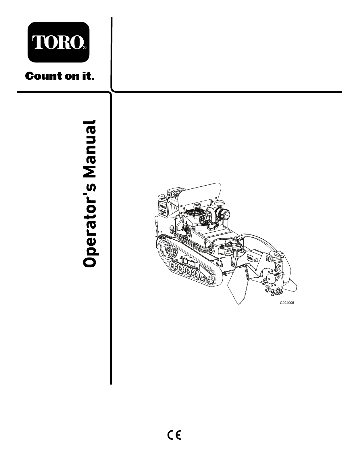
STX-38EFIStumpGrinderwith
Intelli-Sweep
ModelNo.23214—SerialNo.402000000andUp
Registeratwww.T oro.com.
OriginalInstructions(EN)
*3422-804*A
Page 2
ThisproductcomplieswithallrelevantEuropean
directives;fordetails,pleaseseetheseparateproduct
specicDeclarationofConformity(DOC)sheet.
ItisaviolationofCaliforniaPublicResourceCode
Section4442or4443touseoroperatetheengineon
anyforest-covered,brush-covered,orgrass-covered
landunlesstheengineisequippedwithaspark
arrester,asdenedinSection4442,maintainedin
effectiveworkingorderortheengineisconstructed,
equipped,andmaintainedforthepreventionofre.
Theenclosedengineowner'smanualissupplied
forinformationregardingtheUSEnvironmental
ProtectionAgency(EPA)andtheCaliforniaEmission
ControlRegulationofemissionsystems,maintenance,
andwarranty.Replacementsmaybeorderedthrough
theenginemanufacturer.
WARNING
CALIFORNIA
Proposition65Warning
Theengineexhaustfromthisproduct
containschemicalsknowntotheStateof
Californiatocausecancer,birthdefects,
orotherreproductiveharm.
Batteryposts,terminals,andrelated
accessoriescontainleadandlead
compounds,chemicalsknownto
theStateofCaliforniatocause
cancerandreproductiveharm.Wash
handsafterhandling.
Useofthisproductmaycauseexposure
tochemicalsknowntotheStateof
Californiatocausecancer,birthdefects,
orotherreproductiveharm.
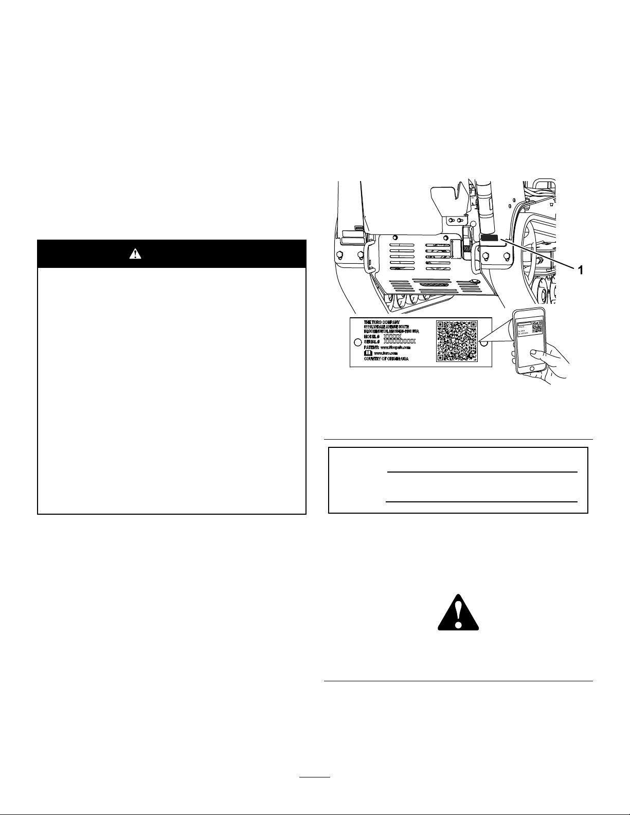
Wheneveryouneedservice,genuineToroparts,or
additionalinformation,contactanAuthorizedService
DealerorToroCustomerServiceandhavethemodel
andserialnumbersofyourproductready.Figure
1illustratesthelocationofthemodelandserial
numbersontheproduct.Writethenumbersinthe
spaceprovided.
Important:Withyourmobiledevice,youcan
scantheQRcodeontheserialnumberdecal(if
equipped)toaccesswarranty,parts,andother
productinformation.
g247193
Figure1
1.Modelandserialnumberplate
ModelNo.
SerialNo.
Introduction
Thismachineisdesignedtogrindandremovetree
stumpsandsurfaceroots.Itisnotintendedtocut
rockoranyothermaterialotherthanwoodandthe
soilaroundastump.
Readthisinformationcarefullytolearnhowtooperate
andmaintainyourproductproperlyandtoavoid
injuryandproductdamage.Youareresponsiblefor
operatingtheproductproperlyandsafely .
YoumaycontactTorodirectlyatwww.T oro.com
forproductsafetyandoperationtrainingmaterials,
accessoryinformation,helpndingadealer,orto
registeryourproduct.
©2018—TheToro®Company
8111LyndaleAvenueSouth
Bloomington,MN55420
Thismanualidentiespotentialhazardsandhas
safetymessagesidentiedbythesafety-alertsymbol
(Figure2),whichsignalsahazardthatmaycause
seriousinjuryordeathifyoudonotfollowthe
recommendedprecautions.
Figure2
1.Safety-alertsymbol
Thismanualuses2wordstohighlightinformation.
Importantcallsattentiontospecialmechanical
informationandNoteemphasizesgeneralinformation
worthyofspecialattention.
Contactusatwww.Toro.com.
2
g000502
PrintedintheUSA
AllRightsReserved
Page 3

Contents
Safety.......................................................................4
SafeOperatingPractices....................................4
SafetyandInstructionalDecals..........................6
Setup......................................................................10
CheckingtheFluidLevels.................................10
ChargingtheBattery.........................................10
OpeningtheLiftValve.......................................10
ProductOverview...................................................10
Controls...........................................................10
Specications..................................................14
Attachments/Accessories.................................14
Operation................................................................14
AddingFuel......................................................14
PerformingDailyMaintenance..........................16
StartingtheEngine...........................................16
DrivingtheMachine..........................................17
ShuttingofftheEngine......................................17
MovingaNon-FunctioningMachine..................17
GrindingaStump..............................................18
SecuringtheMachineforTransport..................19
LiftingtheMachine...........................................19
OperatingTips.................................................19
Maintenance...........................................................20
RecommendedMaintenanceSchedule(s)...........20
Pre-MaintenanceProcedures..............................21
RemovingtheFrontCover................................21
RemovingtheMuferCover.............................21
RemovingtheBottomShield............................22
Lubrication..........................................................22
GreasingtheMachine.......................................22
EngineMaintenance...........................................23
ServicingtheAirCleaner..................................23
ServicingtheEngineOil....................................24
ServicingtheSparkPlug(s)..............................27
FuelSystemMaintenance...................................28
DrainingtheFuelT ank......................................28
ReplacingtheLow-pressureFuelFilter.............28
ServicingtheHigh-PressureFuelFilter.............29
ElectricalSystemMaintenance...........................29
ServicingtheBattery.........................................29
ReplacingtheFuses.........................................31
DriveSystemMaintenance..................................32
ServicingtheTracks.........................................32
CoolingSystemMaintenance..............................34
CleaningtheEngineScreen.............................34
BeltMaintenance................................................35
ReplacingthePump-DriveBelt.........................35
ControlsSystemMaintenance.............................35
AdjustingtheTraction-Control
Alignment......................................................35
HydraulicSystemMaintenance...........................37
HydraulicFluidSpecications...........................37
CheckingtheHydraulic-FluidLevel...................38
ReplacingtheHydraulicFilter...........................38
ChangingtheHydraulicFluid............................38
GrinderMaintenance............................................39
ReplacingtheTeeth..........................................39
Cleaning..............................................................40
RemovingDebrisfromtheMachine..................40
Storage...................................................................41
Troubleshooting......................................................42
Schematics.............................................................44
3
Page 4

Safety
Improperuseormaintenancebytheoperatororowner
canresultininjury.Toreducethepotentialforinjury,
complywiththesesafetyinstructionsandalwayspay
attentiontothesafety-alertsymbol(Figure2),which
meansCaution,Warning,orDanger—personal
safetyinstruction.Failuretocomplywiththe
instructionmayresultinpersonalinjuryordeath.
DANGER
Theremaybeburiedutilitylinesinthework
area.Diggingintothemmaycauseashock
oranexplosion.
Havethepropertyorworkareamarkedfor
buriedlinesanddonotdiginmarkedareas.
Contactyourlocalmarkingserviceorutility
companytohavethepropertymarked(for
example,intheUnitedStates,call811forthe
nationwidemarkingservice).
SafeOperatingPractices
Thisproductiscapableofamputatinghandsandfeet.
Alwaysfollowallsafetyinstructionstoavoidserious
injuryordeath.
WARNING
Engineexhaustcontainscarbonmonoxide,
anodorlesspoisonthatisfatalifinhaled.
Donotruntheengineindoorsorinan
enclosedarea.
•Evaluatetheterraintodeterminewhataccessories
andattachmentsyouneedtoproperlyand
safelyperformthejob.Useonlytheaccessories
andattachmentsthatareapprovedbythe
manufacturer.
•Wearappropriateclothingincludinggloves,eye
protection,longpants,substantialslip-resistant
footwear,andhearingprotection.Tiebacklong
hairanddonotwearlooseclothingorloose
jewelry.
•Inspecttheareawhereyouwillusetheequipment
andremoveallobjects,suchasrocks,toys,and
wire,thatthemachinecouldthrow.
•Checkthattheoperator'spresencecontrols,safety
switches,andshieldsareattachedandfunctioning
properly.Donotoperatethemachineunlessthey
arefunctioningproperly.
FuelSafety
•Useextracarewhenhandlingfuel.Itisammable
anditsvaporsareexplosive.
•Extinguishallcigarettes,cigars,pipes,andother
sourcesofignition.
•Useonlyanapprovedfuelcontainer.
•Donotremovethefuelcaporllthefueltank
whiletheengineisrunningorhot.
•Donotaddordrainfuelinanenclosedspace.
•Donotstorethemachineorfuelcontainerwhere
thereisanopename,spark,orpilotlight,such
asonawaterheaterorotherappliance.
•Ifyouspillfuel,donotattempttostarttheengine;
avoidcreatinganysourceofignitionuntilthefuel
vaporshavedissipated.
Training
•ReadtheOperator'sManualandothertraining
material.Iftheoperator(s)ormechanic(s)cannot
readthisinformation,itistheowner'sresponsibility
toexplainthismaterialtothem.
•Becomefamiliarwiththesafeoperationofthe
equipment,operatorcontrols,andsafetysigns.
•Alloperatorsandmechanicsshouldbetrained.
Theownerisresponsiblefortrainingtheusers.
•Neverletchildrenoruntrainedpeopleoperateor
servicetheequipment.Localregulationsmay
restricttheageoftheoperator.
•Theowner/usercanpreventandisresponsible
foraccidentsorinjuriesoccurringtohimselfor
herself,otherpeopleorproperty .
Preparation
•Beforeusingthemachine,havetheareamarked
forundergroundutilitiesanddonotusethe
machineinmarkedareas.
Operation
•Useyourfullattentionwhileoperatingthe
machine.Donotengageinanyactivitythat
causesdistractions;otherwise,injuryorproperty
damagemayoccur.
•Cleandebrisfromthehydrauliclift,drives,
mufers,andengineaftereachusetohelp
preventres.
•Parkthemachineonalevelsurface,lowerthe
hydrauliclift,disengagethehydraulics,engagethe
parkingbrake(ifapplicable),shutofftheengine,
andremovethekeybeforeleavingtheoperator's
positionforanyreason.
•Donottouchpartsthatmaybehotfromoperation.
Allowthemtocoolbeforeattemptingtomaintain,
adjust,orservicethemachine.
•Neverrunanengineinanenclosedarea.
•Operatethemachineonlyingoodlight,keeping
awayfromholesandhiddenhazards.
4
Page 5

•Ensurethatallthedrivesareinneutralandthe
parkingbrakeisengaged(ifapplicable)before
startingtheengine.Starttheengineonlyfromthe
operator'sposition.
•Slowdownanduseextracareonhillsides.
Ensuretotravelintherecommendeddirectionon
hillsides.Turfconditionscanaffectthestabilityof
themachine.
•Slowdownandusecautionwhenmakingturns,
crossingroadsandsidewalks,andwhenchanging
directionsonslopes.
•Donotchangetheengine-governorsettingor
overspeedtheengine.
•Keepyourhandsandfeetawayfrommovingparts.
•Lookbehindanddownbeforebackingupto
ensurethatthepathisclear.
•Nevercarrypassengersandkeeppetsand
bystandersaway.
•Donotoperatethemachinewhenyouaretired,ill,
orundertheinuenceofalcoholordrugs.
•Usecarewhenloadingorunloadingthemachine
intoatrailerortruck.
•Usecarewhenapproachingblindcorners.
•Ensurethattheareaisclearofpeoplebefore
operatingthemachine.Stopthemachineif
anyoneentersthearea.
•Neverjerkthecontrols;useasteadymotion.
•Operatethemachineinareaswherethereare
noobstaclesincloseproximitytoyou.Failureto
maintainadequatedistancefromtrees,walls,and
otherbarriersmayresultininjuryasthemachine
backsupduringoperationifyouarenotattentive
tothesurroundings.Operatethemachineonlyin
areaswherethereissufcientclearanceforyou
tosafelymaneuver.
•Locatethepinchpointareasmarkedonthe
machineandkeepyourhandsandfeetawayfrom
theseareas.
•Lightningcancausesevereinjuryordeath.If
lightningisseenorthunderisheardinthearea,do
notoperatethemachine;seekshelter.
SlopeOperation
•Slopesareamajorfactorrelatedtoloss-of-control
andtip-overaccidents,whichcanresultinsevere
injuryordeath.Theoperatorisresponsiblefor
safeslopeoperation.operatingthemachineon
anysloperequiresextracaution.Beforeusingthe
machineonaslope,youmust:
–Reviewandunderstandtheslopeinstructions
inthemanualandonthemachine.
–Evaluatethesiteconditionsofthedayto
determineiftheslopeissafeformachine
operation.Alwaysusecommonsense
andgoodjudgmentwhenperformingthis
evaluation.Changesintheterrain,suchas
moisture,canquicklyaffecttheoperationof
themachineonaslope.
•Operateupanddownslopeswiththefrontof
themachineuphill.
•Identifyhazardsatthebaseoftheslope.Do
notoperatethemachineneardrop-offs,ditches,
embankments,waterorotherhazards.The
machinecouldsuddenlyrolloverifawheelortrack
goesovertheedgeortheedgecollapses.Keep
asafedistance(twicethewidthofthemachine)
betweenthemachineandanyhazard.
•Avoidstarting,stopping,orturningthemachineon
aslope.Avoidmakingsuddenchangesinspeed
ordirection;turnslowlyandgradually.
•Keepallmovementsonslopesslowandgradual.
Donotmakesuddenchangesinspeedor
direction.
•Donotoperatethemachineunderanyconditions
wheretraction,steering,orstabilityisinquestion.
Beawarethatoperatingthemachineonwetgrass,
acrossslopesordownhillmaycausethemachine
tolosetraction.Lossoftractiontothewheelsor
tracksmayresultinslidingandalossofbraking
andsteering.Themachinecanslideevenifthe
wheelsortracksarestopped.
•Identifyhazardsatthebaseoftheslope.Do
notoperatethemachineneardrop-offs,ditches,
embankments,waterorotherhazards.The
machinecouldsuddenlyrolloverifawheelortrack
goesovertheedgeortheedgecollapses.Keep
asafedistance(twicethewidthofthemachine)
betweenthemachineandanyhazard.
•Removeormarkobstaclessuchasditches,holes,
ruts,bumps,rocksorotherhiddenhazards.T all
grasscanhideobstacles.Uneventerraincould
overturnthemachine.
•Donotparkthemachineonahillsideorslope
withoutloweringthehydrauliclifttotheground.
MaintenanceandStorage
•Parkthemachineonalevelsurface,lowerthe
hydrauliclift,disengagethehydraulics,engagethe
parkingbrake(ifapplicable),shutofftheengine,
andremovethekey.Waitforallmovingpartsto
stopbeforeadjusting,cleaning,orrepairingthe
machine.
•Cleandebrisfromthehydrauliclift,drives,
mufers,andenginetohelppreventres.Wipe
upanyspilledoilorfuel.
•Allowtheenginetocoolbeforestoringanddonot
storethemachinenearames.
•Neverallowuntrainedpersonneltoservicethe
machine.
5
Page 6
•Usejackstandstosupportthecomponentswhen
required.
•Carefullyreleasepressurefromcomponentswith
storedenergy.
•Keepyourhandsandfeetawayfromthemoving
parts.Ifpossible,donotmakeadjustmentswith
theenginerunning.
•Disconnectthebatteryorremovethespark-plug
wiresbeforemakinganyrepairs.Disconnect
thenegativeterminalrstandthepositivelast;
connectthepositiverstandthenegativelast.
•Chargethebatteryinanopen,well-ventilated
area,awayfromsparkandames.Unplugthe
chargerbeforeconnectingordisconnectingitfrom
thebattery.Wearprotectiveclothinganduse
insulatedtools.
•Batteryacidispoisonousandcancauseburns.
Avoidcontactwithskin,eyes,andclothing.Protect
yourface,eyes,andclothingwhenworkingwitha
battery.
•Batterygassescanexplode.Keepcigarettes,
sparks,andamesawayfromthebattery.
•Keepallpartsingoodworkingconditionandall
hardwaretightened.Replaceallwornordamaged
decals.
•Keepallnutsandboltstight.Keeptheequipment
ingoodcondition.
•Nevertamperwiththesafetydevices.
•Keepthemachinefreeofdebrisbuildup.Wipeup
anyspilledoilorfuel.
•Shutofftheengine,removethekey,andinspect
themachineifyoustrikeanobject.Makeany
necessaryrepairsbeforestarting.
•UseonlygenuineTororeplacementparts.
•Keepyourbodyandhandsawayfrompinhole
leaksornozzlesthatejecthigh-pressurehydraulic
uid.Usecardboardorpapertondhydraulic
leaks;neveruseyourhands.Hydraulicuid
escapingunderpressurecanpenetrateskinand
causeinjuryrequiringsurgerywithinafewhours
byaqualiedsurgeon;otherwise,gangrenemay
result.
SafetyandInstructionalDecals
Safetydecalsandinstructionsareeasilyvisibletotheoperatorandarelocatednearanyarea
ofpotentialdanger.Replaceanydecalthatisdamagedormissing.
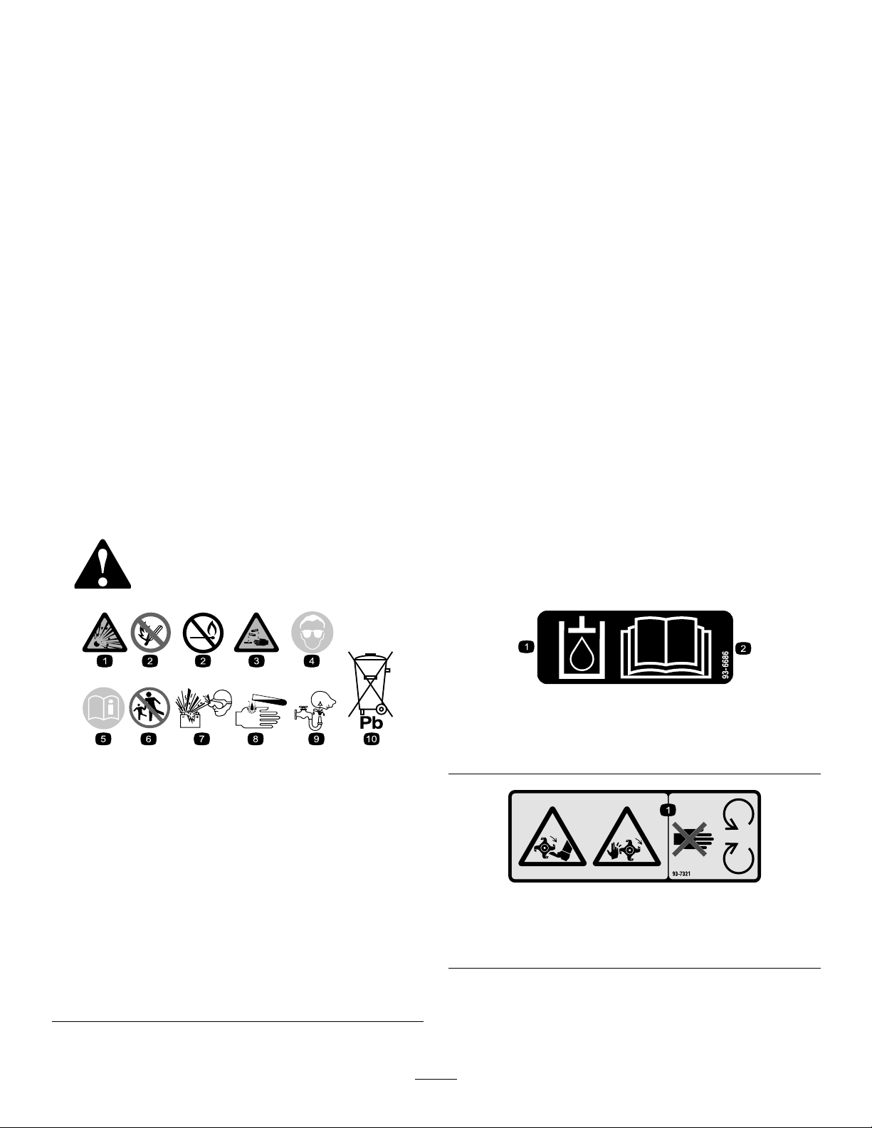
BatterySymbols
Someorallofthesesymbolsareonyourbattery .
1.Explosionhazard
2.Nore,opename,or
smoking
3.Causticliquid/chemical
burnhazard
4.Weareyeprotection.9.Flusheyesimmediately
5.ReadtheOperator's
Manual.
6.Keepbystandersasafe
distancefromthebattery.
7.Weareyeprotection;
explosivegasescan
causeblindnessandother
injuries.
8.Batteryacidcancause
blindnessorsevereburns.
withwaterandgetmedical
helpfast.
10.Containslead;donot
discard
decal93-6686
93-6686
1.Hydraulicuid
decalbatterysymbols
2.ReadtheOperator'sManual.
decal93-7321
93-7321
1.Cutting/dismembermenthazardofhandsandfeet,rotating
knives/blades—stayawayfrommovingparts.
6
Page 7
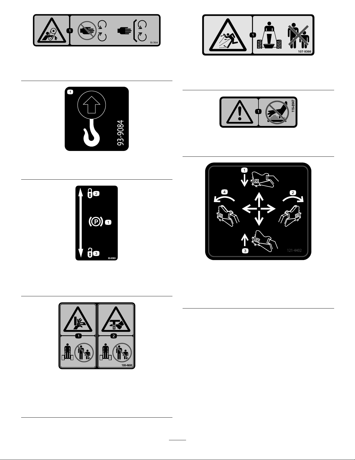
93-7814
1.Entanglementhazard,belt—stayawayfrommovingparts;
keepallguardsandshieldsinplace.
93-9084
1.Liftpoint/Tie-downpoint
decal93-7814
decal107-9366
107-9366
1.Thrownobjecthazard—keepbystandersasafedistance
awayfromthemachine.
decal115-2047
115-2047
1.Warning—donottouchthehotsurface.
decal93-9084
93-9363
1.Parkingbrake3.Unlocked
2.Locked
100-4650
1.Crushinghazardofhand—keepbystandersasafedistance
awayfromthemachine.
2.Crushinghazardoffoot—keepbystandersasafedistance
awayfromthemachine.
decal93-9363
decal121-4402
121-4402
1.Pushforwardtolowerthe
stumpgrinder.
2.Moverighttomovethe
stumpgrindertotheright.
decal100-4650
3.Pullbacktoraisethe
stumpgrinder.
4.Movelefttomovethe
stumpgrindertotheleft.
7
Page 8
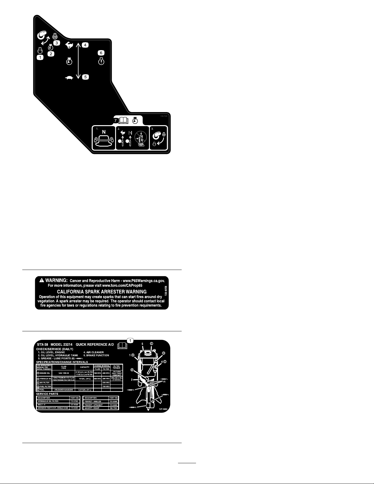
130-7580
1.Engine—start5.Enginespeed—slow
2.Engine—run6.Engineindicatorlight
3.Engine—stop
7.ReadtheOperator's
Manualbeforestartingthe
engine—1)Ensurethat
thetractioncontrolisin
theneutralposition;2)
Movethethrottleleverto
theFastposition,close
thechoke(ifapplicable),
anddonotoperatethe
joystick;3)Turnthekeyto
starttheengine.
4.Enginespeed—fast
133-8056
decal130-7580
decal133-8056
137-4869
1.ReadtheOperator’sManual.
decal137-4869
8
Page 9
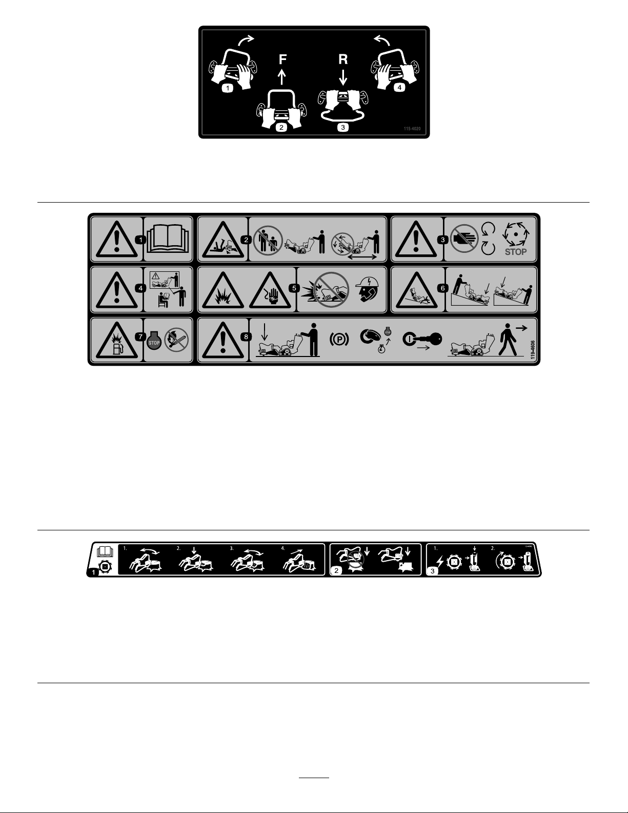
115-4020
1.Turnright3.Reverse
2.Forward
119-4606
decal115-4020
4.Turnleft
decal119-4606
1.Warning—readtheOperator'sManual.
5.Explosionandelectricshockhazard—donotdiginareaswith
buriedutilitylines;contactlocalpowerorganizationsbefore
digging.
2.Cutting/dismembermenthazard;grinder—keepbystanders
asafedistanceawayfromthemachine;donotoperatethe
6.Tipping/crushinghazard—lowerthecutterheadwhen
operatingonslopes.
grinderheadwhiletransportingthemachine.
3.Warning—stayawayfrommovingparts;waitforallmoving
partstostop.
7.Explosionhazard,fueling—shutofftheengineandextinguish
allameswhenfueling.
4.Warning—donotoperatethismachineunlessyouaretrained.8.Warning—lowerthegrinderhead,engagetheparkingbrake
(ifapplicable),shutofftheengine,andremovethekeybefore
leavingthemachine.
121-4382
1.ReadtheOperator’sManualforinformationonoperatingthe
grinder—1)Grindhorizontallyalongtheedgeofthestump;2)
Lowerthegrinderslightlyintothestump;3)Grindhorizontally
downtogroundlevel;4)Movethegrinderforward.
2.Donotstartgrindinginthemiddleofthestump;startgrinding
attheedgeofthestump.
3.1)Topowerthegrinder,pressthesafetylockandthetrigger
together;2)Tokeepthegrinderrunning,holdthetrigger.
decal121-4382
9
Page 10
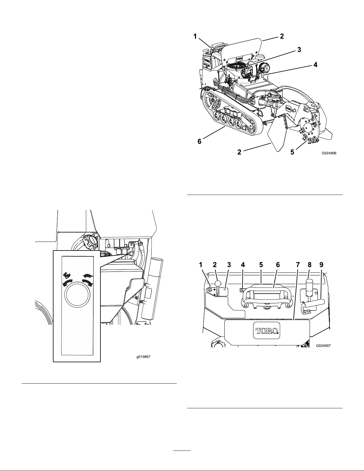
Setup
CheckingtheFluidLevels
Beforestartingtheengineforthersttime,check
theengine-oilandhydraulic-uidlevels.Refertothe
followingsectionsformoreinformation:
•CheckingtheEngine-OilLevel(page24)
•CheckingtheHydraulic-FluidLevel(page38)
ChargingtheBattery
Chargethebattery;refertoChargingtheBattery
(page30)formoreinformation.
ProductOverview
OpeningtheLiftValve
Beforeyoucanraisethegrinderandmovethe
machine,youmustopentheliftvalvelocatedunder
thecontrolpanel(Figure3).Turntheknobcounter
clockwisetoallowyoutoliftthegrinder.Thefarther
youturntheknob,thefastertheheadraisesand
lowerswhenactivated.
Figure4
1.Controlpanel
2.Chipshield
3.Engine
4.Battery6.Track
5.Grinder
Controls
Becomefamiliarwithallthecontrols(Figure5)before
youstarttheengineandoperatethemachine.
ControlPanel
g024906
Figure3
g024907
Figure5
g019867
1.Keyswitch
2.Throttlelever
3.Engineindicatorlight
4.Hourmeter9.Handle
5.Tractioncontrol
10
6.Referencebar
7.Reversesafetyplate
8.Grindercontrollever
Page 11
KeySwitch
Thekeyswitch,usedtostartandshutofftheengine,
has3positions:OFF,RUN,andST ART.Referto
StartingtheEngine(page16).
ThrottleLever
Movethecontrolforwardtoincreasetheenginespeed
andrearwardtodecreasetheenginespeed.
HourMeter
Thehourmeterdisplaysthenumberofhoursof
operationthathavebeenloggedonthemachine.
ReferenceBar
Whendrivingthemachine,usethereferencebar
asahandleandaleveragepointforcontrollingthe
machine.Toensuresmooth,controlledoperation,
donottakebothhandsoffthereferencebarwhile
operatingthemachine.
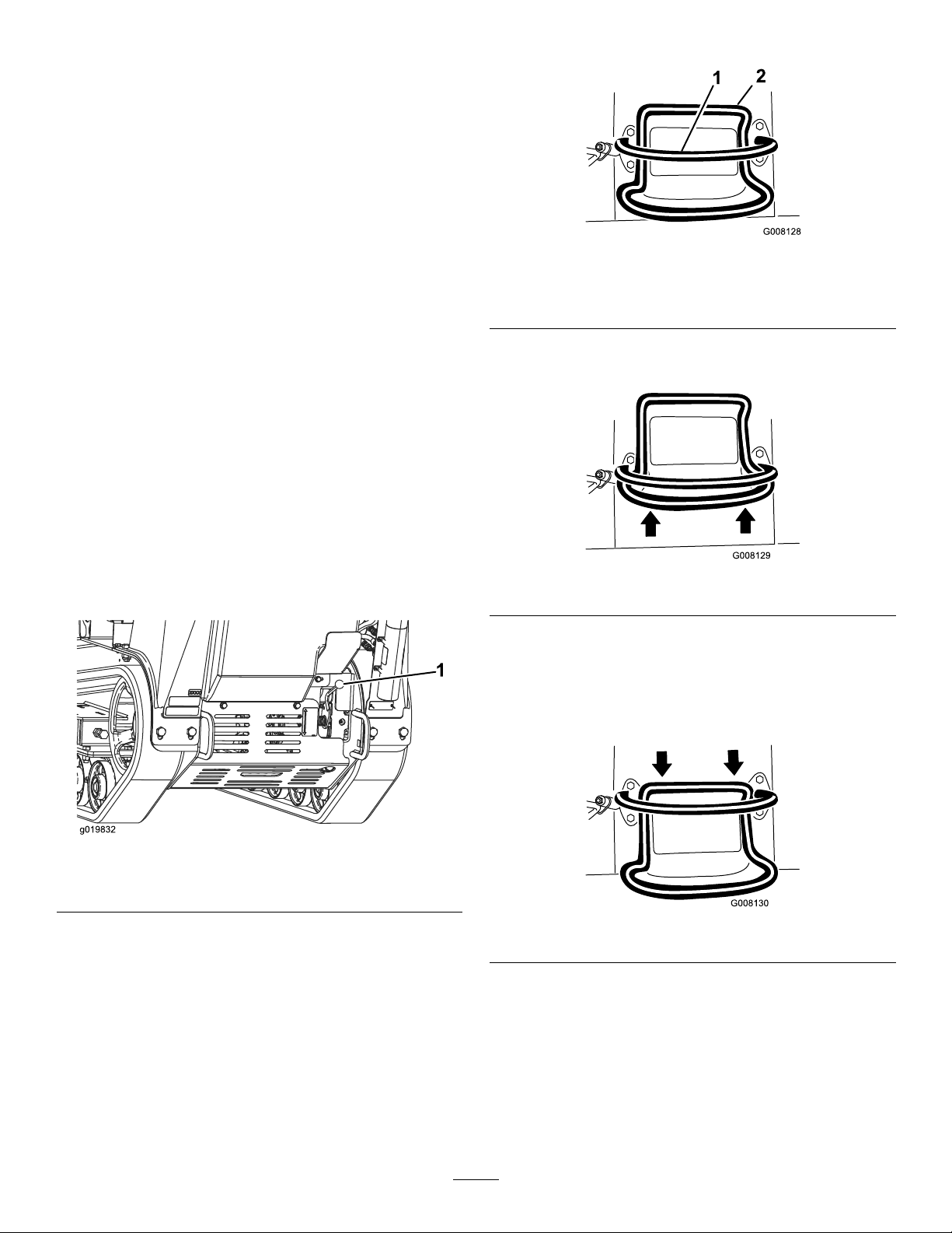
TractionControl
g008128
Figure7
1.Referencebar
2.Tractioncontrol
•Tomoveforward,movethetractioncontrolforward
(Figure8).
Parking-BrakeLever
Toengagetheparkingbrake,lifttheleverupward.
Todisengagetheparkingbrake,pushthelever
downward.
Figure6
1.Parking-brakelever
g008129
Figure8
•Tomoverearward,movethetractioncontrol
rearward(Figure9).
Important:Whenreversing,lookbehindyou
forobstructionsandkeepyourhandsonthe
referencebar.
g019832
g008130
Figure9
11
Page 12
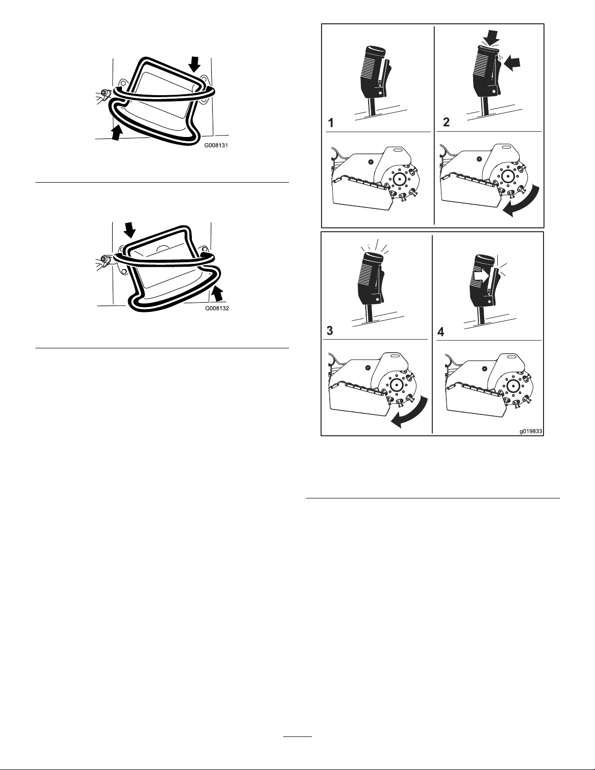
•Toturnright,rotatethetractioncontrolclockwise
(Figure10).
Figure10
•Toturnleft,rotatethetractioncontrol
counterclockwise(Figure11).
g008131
Figure11
•Tostopthemachine,releasethetractioncontrol
(Figure7).
Note:Thefartheryoumovethetractioncontrolin
anydirection,thefasterthemachinemovesinthat
direction.
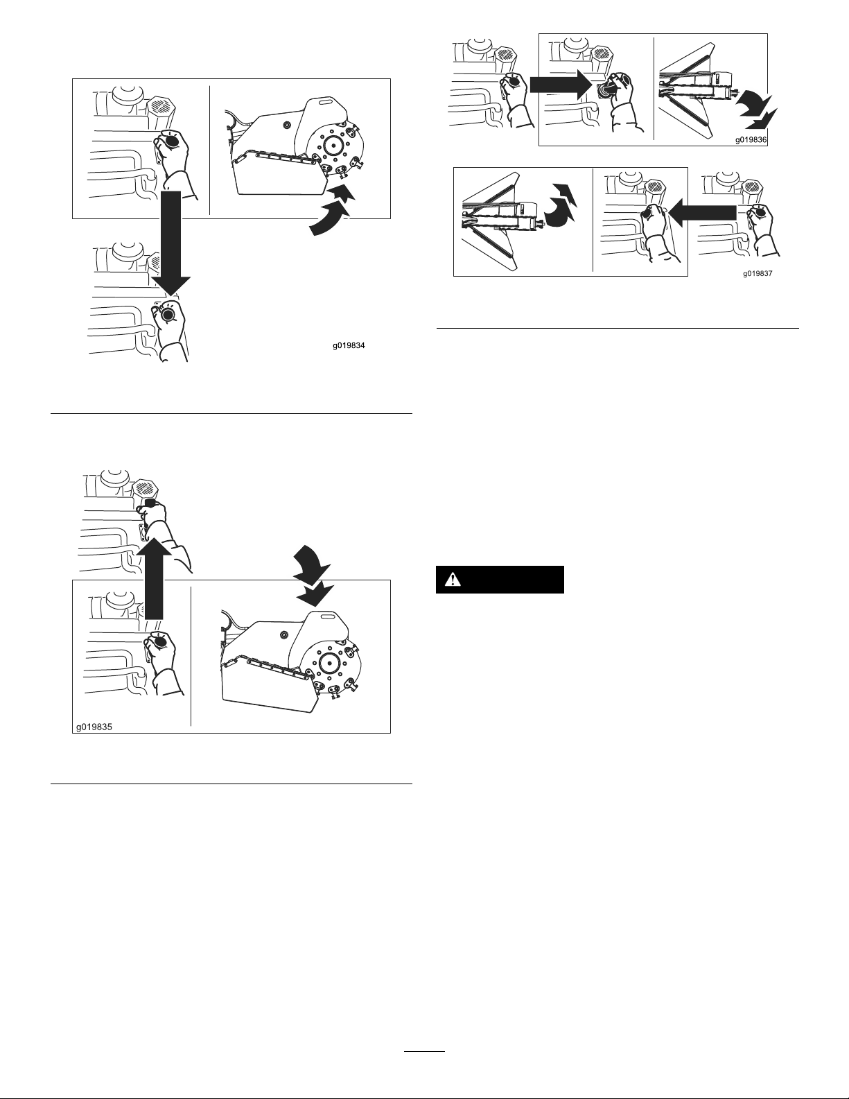
GrinderControl/Hydraulic-Lift
Lever
Operatethegrinderusingthegrindercontrollever
asfollows:
•Tostartthegrinder(Figure12),squeezethe
triggerandthenpresstheredbuttononthetopof
thelever.Oncethegrinderhasstarted,youcan
releasetheredbutton.
•Tostopthegrinder(Figure12),releasethetrigger
formorethanahalfsecond.
g008132
g019833
Figure12
1.Neutral3.Runthegrinder
2.Startthegrinder4.Stopthegrinder
Note:Ifyouareoperatingthegrinderand
momentarilyreleasethetrigger(i.e.,lessthana
halfsecond),thegrindercontinuestooperate.
12
Page 13
•Toraisethegrinder,pulltheleverrearward(Figure
13).
g019836
g019837
Figure15
Figure13
•Tolowerthegrinder,pushtheleverforward(Figure
14).
Figure14
g019834
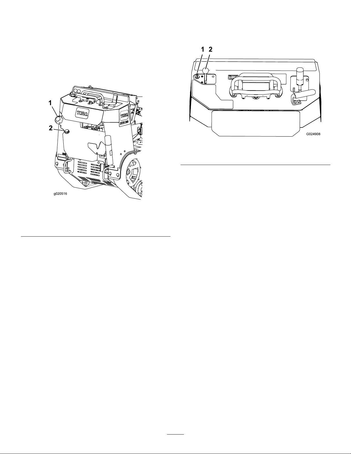
Lift/LowerSpeedControl
Youcanchangehowquicklythegrinderheadraises
andlowersusingthelift/lowerspeedcontrol,located
undertherightsideofthecontrolpanel(Figure16).
Rotatethedialcounterclockwisetoincreasethe
speedorrotateitclockwisetoreducethespeed.
Ifyoumuststopthemachinewiththegrinderhead
raised,turnthecontroldialallthewayclockwiseto
lockthegrinderheadbeforeleavingthemachineor
performinganymaintenance
CAUTION
Ifyouleavethegrinderheadintheraised
positionwithoutturningthelift/lowerspeed
controldialallthewayclockwise,thegrinder
couldlower,crushingyouorbystanders.
Wheneverpossible,lowerthegrindertothe
groundbeforeshuttingofftheengine.If
g019835
youmustkeepthegrinderheadraised,turn
thelift/lowerspeedcontroldialalltheway
clockwisetolockthegrinder.
•Torotatethegrindertotherightorleft,movethe
leverinthedesireddirection(Figure15).
13
Page 14
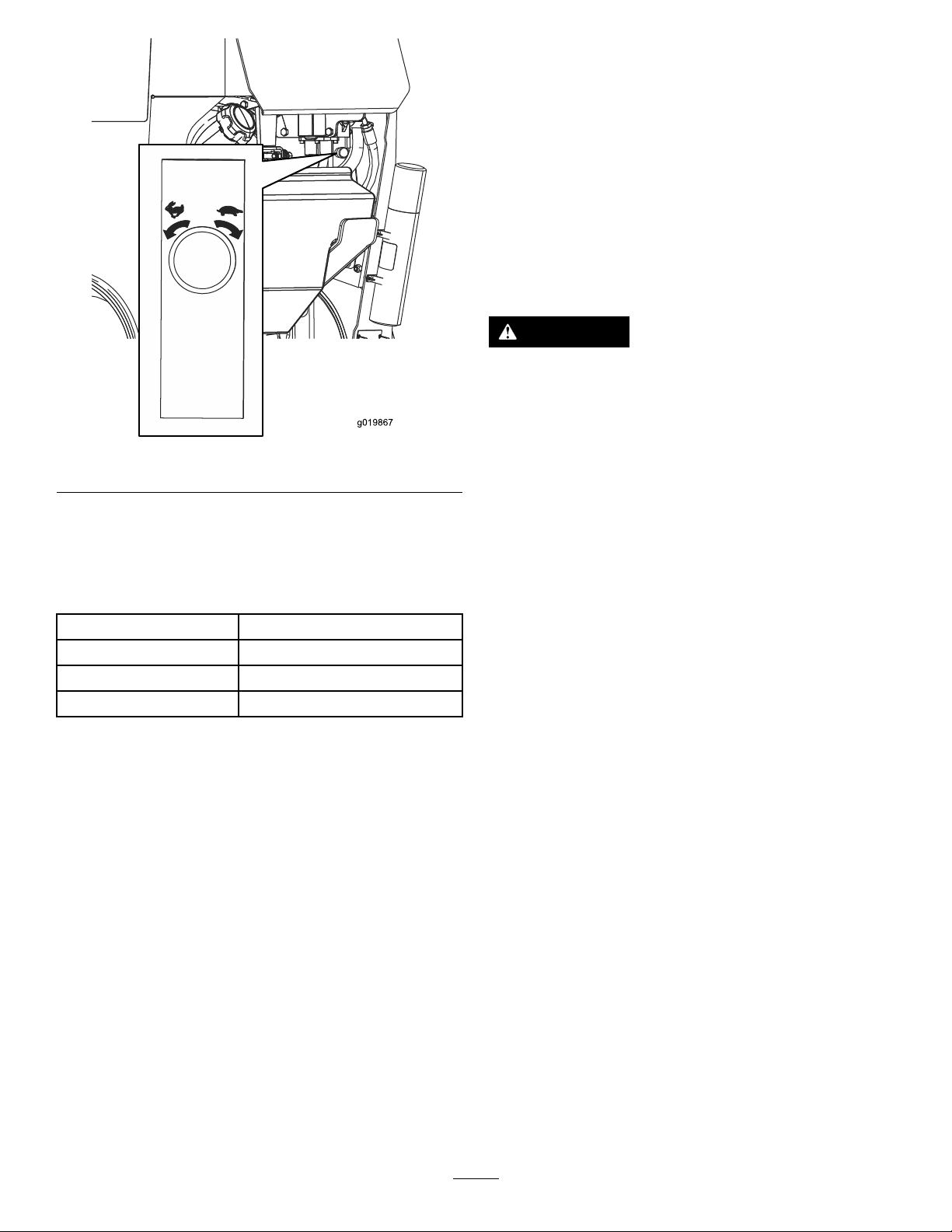
Figure16
Operation
Note:Determinetheleftandrightsidesofthe
machinefromthenormaloperatingposition.
Important:Beforeoperatingthemachine,check
theuidlevels,andremovedebrisfromthe
machine.Ensurethattheareaisclearofpeople
anddebris.Youshouldalsoknowandhave
markedthelocationsofallutilitylines.
AddingFuel
DANGER
Incertainconditions,fuelisextremely
ammableandhighlyexplosive.Areor
explosionfromfuelcanburnyouandothers
andcandamageproperty.
g019867
•Fillthefueltanksoutdoors,inanopen
area,whentheengineiscold.Wipeupany
fuelthatspills.
Specications
Note:Specicationsanddesignaresubjectto
changewithoutnotice.
Width
Length
Height
Weight
Attachments/Accessories
AselectionofT oroapprovedattachmentsand
accessoriesisavailableforusewiththemachine
toenhanceandexpanditscapabilities.Contact
yourAuthorizedServiceDealerorauthorizedT oro
distributororgotowww.Toro.comforalistofall
approvedattachmentsandaccessories.
Toensureoptimumperformanceandcontinuedsafety
certicationofthemachine,useonlygenuineT oro
replacementpartsandaccessories.Replacement
partsandaccessoriesmadebyothermanufacturers
couldbedangerous,andsuchusecouldvoidthe
productwarranty.
86cm(34inches)
241cm(95inches)
130cm(51inches)
794kg(1,750lb)
•Neverllthefueltanksinsideanenclosed
trailer.
•Neversmokewhenhandlingfuelandstay
awayfromanopenameorwherefuel
fumesmaybeignitedbyaspark.
•Storefuelinanapprovedcontainerand
keepitoutofthereachofchildren.Never
buymorethana30-daysupplyoffuel.
•Donotoperatewithoutentireexhaust
systeminplaceandinproperworking
condition.
14
Page 15

DANGER
Incertainconditionsduringfueling,static
electricitycanbereleased,causingaspark
thatcanignitethefuelvapors.Areor
explosionfromfuelcanburnyouandothers
andcandamageproperty.
•Alwaysplacefuelcontainersontheground
awayfromyourvehiclebeforelling.
•Donotllfuelcontainersinsideavehicle
oronatruckortrailerbed,becauseinterior
carpetsorplastictruckbedlinersmay
insulatethecontainerandslowthelossof
anystaticcharge.
•Whenpractical,removeequipmentfrom
thetruckortrailerandrefueltheequipment
withitswheelsontheground.
•Ifthisisnotpossible,thenrefuelsuch
equipmentonatruckortrailerfroma
portablecontainerratherthanfroma
fuel-dispensernozzle.
RecommendedFuel
•Forbestresults,useonlyclean,fresh(lessthan
30daysold),unleadedgasolinewithanoctane
ratingof87orhigher((R+M)/2ratingmethod).
•Ethanol:Gasolinewithupto10%ethanol
(gasohol)or15%MTBE(methyltertiarybutyl
ether)byvolumeisacceptable.Ethanoland
MTBEarenotthesame.Gasolinewith15%
ethanol(E15)byvolumeisnotapprovedforuse.
Neverusegasolinethatcontainsmorethan
10%ethanolbyvolume,suchasE15(contains
15%ethanol),E20(contains20%ethanol),orE85
(containsupto85%ethanol).Usingunapproved
gasolinemaycauseperformanceproblemsand/or
enginedamagewhichmaynotbecoveredunder
warranty.
•Donotusegasolinecontainingmethanol.
•Donotstorefueleitherinthefueltankorfuel
containersoverthewinterunlessyouuseafuel
stabilizer.
•Donotaddoiltogasoline.
•Ifyoumustuseafuel-dispensernozzle,
keepthenozzleincontactwiththerimof
thefueltankorcontaineropeningatall
timesuntilfuelingiscomplete.
WARNING
Fuelisharmfulorfatalifswallowed.
Long-termexposuretovaporscancause
seriousinjuryandillness.
•Avoidprolongedbreathingofvapors.
•Keepyourfaceawayfromthenozzleand
fueltankopening.
•Keepfuelawayfromyoureyesandskin.
UsingStabilizer/Conditioner
Useafuelstabilizer/conditionerinthemachineto
providethefollowingbenets:
•Keepsfuelfreshlongerwhenusedasdirectedby
thefuel-stabilizermanufacturer
•Cleanstheenginewhileitruns
•Eliminatesgum-likevarnishbuildupinthefuel
system,whichcauseshardstarting
Important:Donotusefueladditives
containingmethanolorethanol.
Addthecorrectamountoffuelstabilizer/conditioner
tothefuel.
Note:Afuelstabilizer/conditionerismost
effectivewhenmixedwithfreshfuel.T ominimize
thechanceofvarnishdepositsinthefuelsystem,
usefuelstabilizeratalltimes.
15
Page 16
FillingtheFuelTank
1.Parkthemachineonalevelsurface,engage
theparkingbrake(ifapplicable),andlowerthe
hydrauliclift.
2.Shutofftheengine,removethekey,andallow
theenginetocool.
3.Cleanaroundthefuel-tankcapandremoveit
(Figure17).
StartingtheEngine
1.Movethethrottlelevermidwaybetweenthe
SLOWandFASTpositions(Figure18).
g024908
Figure18
1.Key2.Throttlelever
2.TurnthekeytotheONposition(Figure18).
Whentheenginestarts,releasethekey.
Figure17
1.Fuel-tankcap
2.Fuelgauge
4.Fillthetankwithfueltoabout6to13mm(1/4to
1/2inch)belowthebottomofthellerneck.
Important:Thisspaceinthetankallows
fueltoexpand.Donotllthefueltank
completelyfull.
5.Installthefuel-tankcapsecurely.
6.Wipeupanyspilledfuel.
PerformingDaily Maintenance
Beforestartingthemachineeachday ,performthe
EachUse/DailyprocedureslistedinMaintenance
(page20).
Important:Donotengagethestarterfor
g020516
morethan10secondsatatime.Iftheengine
failstostart,allowa30-secondcooldown
periodbetweenattempts.Failuretofollow
theseinstructionscanburnoutthestarter
motor.
3.Movethethrottlelevertothedesiredsetting
(Figure18).
Important:Iftheengineisrunathigh
speedswhenthehydraulicsystemiscold
(i.e.,whentheambientairtemperatureis
nearfreezingorlower),hydraulicsystem
damagecouldoccur.Whenstartingthe
engineincoldconditions,allowtheengine
toruninthemiddlethrottlepositionfor
2to5minutesbeforemovingthethrottle
tofast(rabbit).Atnormaltohighambient
temperatures,runthemachineatfullthrottle
forthebestperformanceandcooling.
Note:Iftheoutdoortemperatureisbelow
freezing,storethemachineinagaragetokeep
itwarmerandaidinstarting.
16
Page 17
DrivingtheMachine
MovingaNon-Functioning
Usethetractioncontrolstomovethemachine.The
fartheryoumovethetractioncontrolsinanydirection,
thefasterthemachinemovesinthatdirection.
Releasethetractioncontrolstostopthemachine.
CAUTION
Whenreversing,youmaybackintostationary
objectsoroverbystandersandcauseserious
personalinjuryordeath.
Lookbehindyouforobstructionsor
bystandersandkeepyourhandsonthe
referencebar.
Thethrottlecontrolregulatestheenginespeedas
measuredinrpm(revolutionsperminute).Placethe
throttleleverintheFASTpositionforbestperformance.
Youcan,however,usethethrottlepositiontooperate
atslowerspeeds.
ShuttingofftheEngine
1.Parkthemachineonalevelsurface,engage
theparkingbrake(ifapplicable),andlowerthe
hydrauliclift.
2.MovethethrottlelevertotheSLOWposition
(Figure18).
3.Iftheenginehasbeenworkinghardorishot,let
itidleforaminutebeforeturningthekeyswitch
totheOFFposition.
Note:Thishelpstocooltheenginebeforeyou
shutitoff.Inanemergency ,youcanshutoff
theengineimmediately.
Machine
Important:Donottoworpullthemachine
withoutrstopeningthetowvalves,oryouwill
damagethehydraulicsystem.
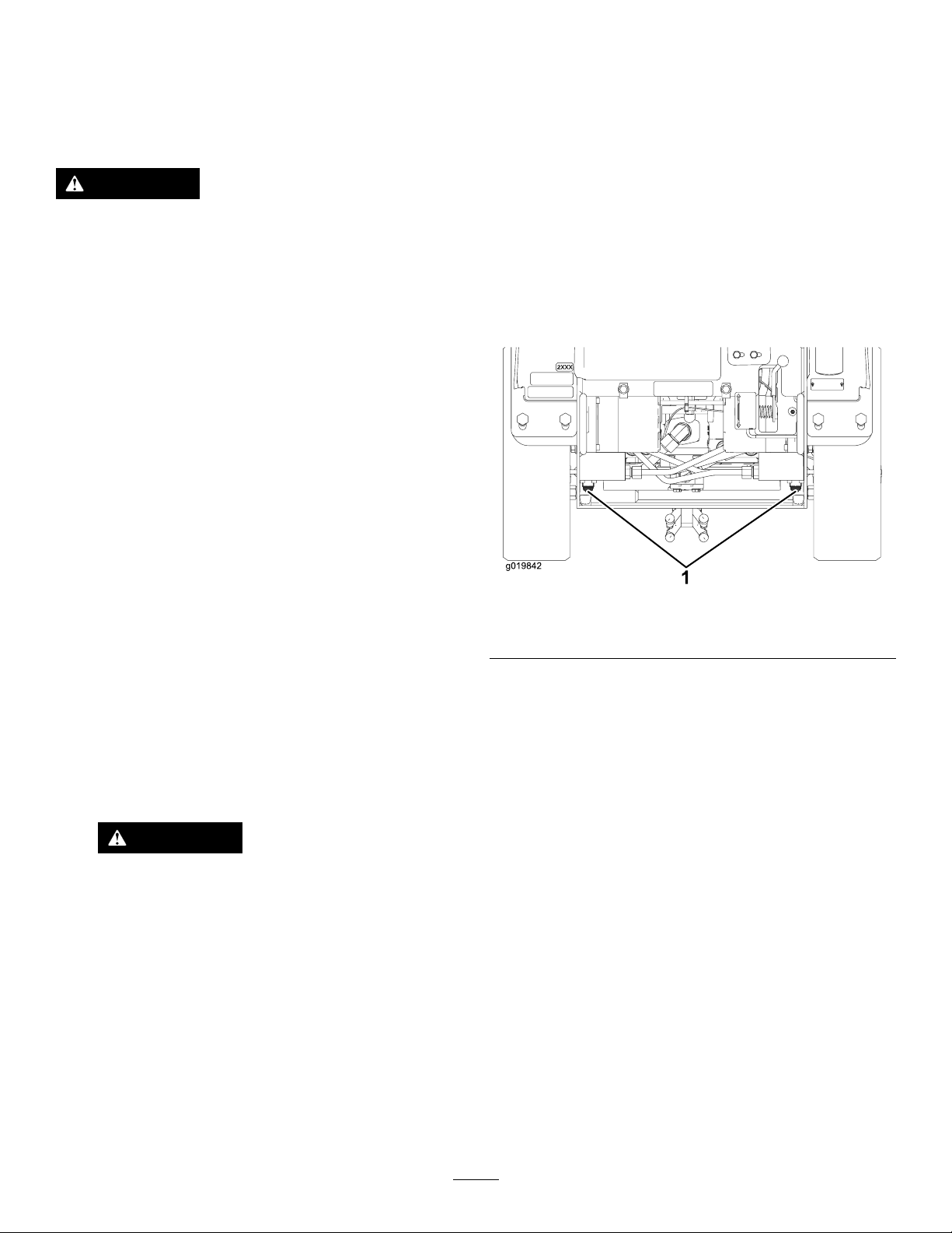
1.Engagetheparkingbrakeandlowerthe
hydrauliclift.
2.Shutofftheengineandremovethekey.
3.Removethebottomshield.
4.Usingawrench,turnthetowvalvesonthe
hydraulicpumpstwicecounter-clockwise(Figure
19).
g019842
Figure19
1.Towvalves
5.Installthebottomshieldandtowthemachine
asrequired.
6.Afterrepairingthemachine,closethetowvalves
beforeoperatingit.
4.TurnthekeyswitchtotheOFFpositionand
removethekey.
CAUTION
Achildoruntrainedbystandercould
attempttooperatethemachineandbe
injured.
Removethekeyfromtheswitchwhen
leavingthemachine,evenifjustforafew
seconds.
17
Page 18
GrindingaStump
DANGER
Thismachineiscapableofamputatinghands
andfeet.
•Stayintheoperatingpositionwhilethe
machineisrunning,andkeepawayfrom
movingparts.
•Keepallbystandersasafedistanceaway
fromthemachine.
•Stopthemachineimmediatelyifany
peopleoranimalsentertheworkarea.
WARNING
Grindingastumpthrowswoodchips,soil
andotherdebrisintotheair,whichcould
injureyouorbystandersandcoulddamage
property.
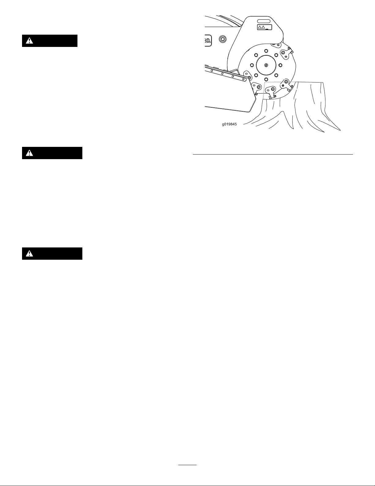
g019845
Figure20
5.Lowerthegrinderaboutaninchandswingit
backoverthestump.
6.Repeatsteps4and5untilyouhavereached
groundlevel.
•Alwaysweareyeprotectionwhenusing
thegrinder.
•Keepallbystandersasafedistanceaway
fromthegrinder.
WARNING
Thegrinderisveryloudwhencuttingastump
andcandamageyourears.
Alwayswearhearingprotectionwhenusing
thegrinder.
1.Starttheengine,raisethegrinder,setthe
throttlelevertotheFASTposition,andmovethe
machinetothestumptobeground.
2.Usethegrindercontrolleverandthetraction
controltopositionthegrindertothesideofthe
frontofthestump,about2cm(1inch)below
thesurface(Figure20).
3.Startthegrinderandwaitforittogetuptofull
speed.
7.Raisethegrindersothatitisaboutaninch
belowthetopoftheremainingstump,movethe
machineforwardafewcentimeters(inches),
andrepeatsteps4through6untilyouhave
groundawaytheentirestump.
8.Ifthereareanylargerootstobeground,position
thegrinderovereachrootandusethetraction
controlandgrindercontroltomovethegrinder
alongtheroot,grindingitaway.
9.Cleandebrisfromthehydrauliclift,drives,
mufers,andengineaftereachuse.
Note:RefertoRemovingtheMuferCover
(page21)toaccessthemufer.
4.Usethegrindercontrollevertoswingthegrinder
slowlyacrossthefaceofthestump,cutting
awayaswathofchips(Figure20).
Important:Thegrinderautomaticallyslows
downthespeedatwhichitswingsintothe
stumptomaintaintheoptimumywheel
speedandnotbogdowninthewood.
18
Page 19
SecuringtheMachinefor
OperatingTips
Transport
Important:Donotoperateordrivethemachine
onroadways.
1.Parkthemachineonalevelsurface,engage
theparkingbrake(ifapplicable),andlowerthe
hydrauliclift.
2.Shutofftheengineandremovethekey.
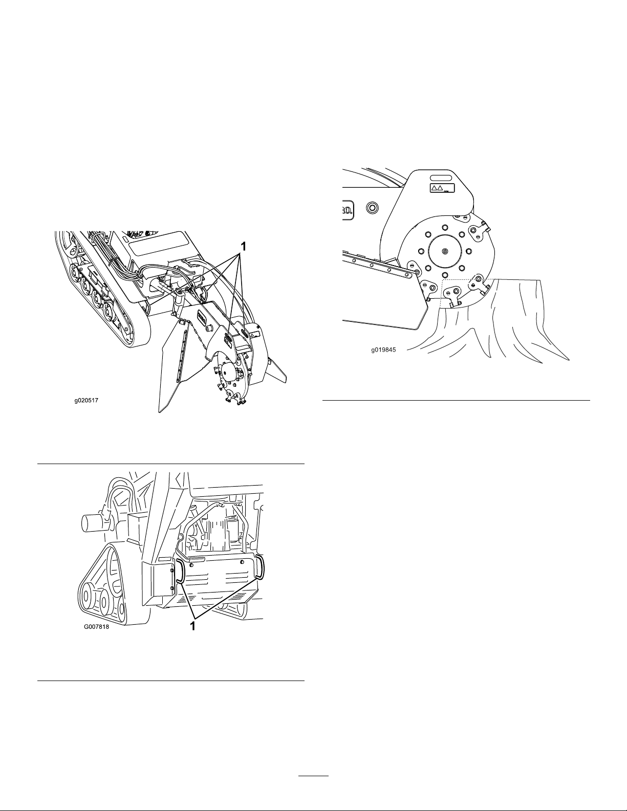
3.Securethemachinetoatrailerwithchainsor
strapsusingthetie-down/liftloopsatthefront
andrearofthemachine(Figure21andFigure
22).Refertoyourlocalordinancesfortrailerand
tie-downrequirements.
•Cleantheareaoftrash,branches,androcks
beforeoperatingtopreventequipmentdamage.
•Alwaysusefullthrottle(maximumenginespeed)
whengrinding.
•Cuttheedgesofthestumpformoreefcient
grinding.Onceyourcuttingswathiscloseto1/4
ofthewheeldiameter,lowerthegrinderandbegin
cuttingontheedgeagain.
1.Fronttie-down/liftloops
1.Reartie-down/liftloops
Figure21
Figure22
g019845
Figure23
g020517
•Listentotheengineandwatchthegrinderwheel
speedtomaintainthespeedofthewheel.Slow
downtheheadsweepbyfeatheringthejoystickas
cuttingbecomesdifcult.
•Asyougrindfromlefttoright,mostofthedebris
goestotheleftofthegrinderwheel.Whenyou
grindfromtherighttoleft,thedebrisgoestothe
right.
•Youmayalsogrindastumpfromthesidetolessen
turfdamage.
g007818
LiftingtheMachine
Youcanliftthemachineusingthetie-down/liftloops
asliftpoints(Figure21andFigure22).
19
Page 20
Maintenance
Note:Determinetheleftandrightsidesofthemachinefromthenormaloperatingposition.
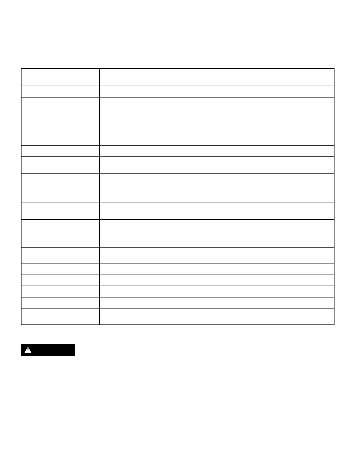
RecommendedMaintenanceSchedule(s)
MaintenanceService
Interval
Aftertherst50hours
Beforeeachuseordaily
Aftereachuse
Every25hours
Every100hours
Every150hours
Every200hours
Every250hours
MaintenanceProcedure
•Checkandadjustthetracktension.
•Greasethemachine.(Greaseitimmediatelyaftereverywashing.)
•Checktheengine-oillevel.
•Checktheconditionofandcleanthetracks.
•Cleantheenginescreen.
•Checktheconditionoftheteeth;rotateorreplaceanythatarewornordamaged
andtorquethenutsforallteeth.
•Checkforloosefasteners.
•Removedebrisfromthemachine.
•Checkthebatteryelectrolytelevel.
•Checkthehydraulic-uidlevel.
•Changetheengineoilandoillter(moreoftenindirtyordustyconditions).
•Checkandadjustthetracktension.
•Checkthehydrauliclinesforleaks,loosettings,kinkedlines,loosemounting
supports,wear,weather,andchemicaldeteriorationandrepairifnecessary.
•Inspecttheprimarylter.
•Replacethelow-pressurefuellter(moreoftenindirtyordustyconditions).
•Changetheengine-oillter.
•Replacethehydrauliclter.
•Checkandgreasetheroadwheels.
Every300hours
Every400hours
Every500hours
Every600hours
Every1,500hours
Yearlyorbeforestorage
•Replacetheprimaryairlter(moreoftenindustyorsandyconditions).
•Checktheinnerairlter.
•Changethehydraulicuid.
•Replaceandgapthesparkplug(s).
•Replacetheinnerairlter.
•Replaceallmovinghydraulichoses.
•Checkandadjustthetracktension.
•Touchupchippedpaint.
Important:Refertoyourengineowner'smanualforadditionalmaintenanceprocedures.
CAUTION
Ifyouleavethekeyinthekeyswitch,someonecouldaccidentlystarttheengineandseriously
injureyouorotherbystanders.
Removethekeyfromthekeyswitchanddisconnectthewiresfromthesparkplugsbefore
youdoanymaintenance.Setthewiresasidesothattheydonotaccidentallycontactthe
sparkplugs.
20
Page 21
Pre-Maintenance
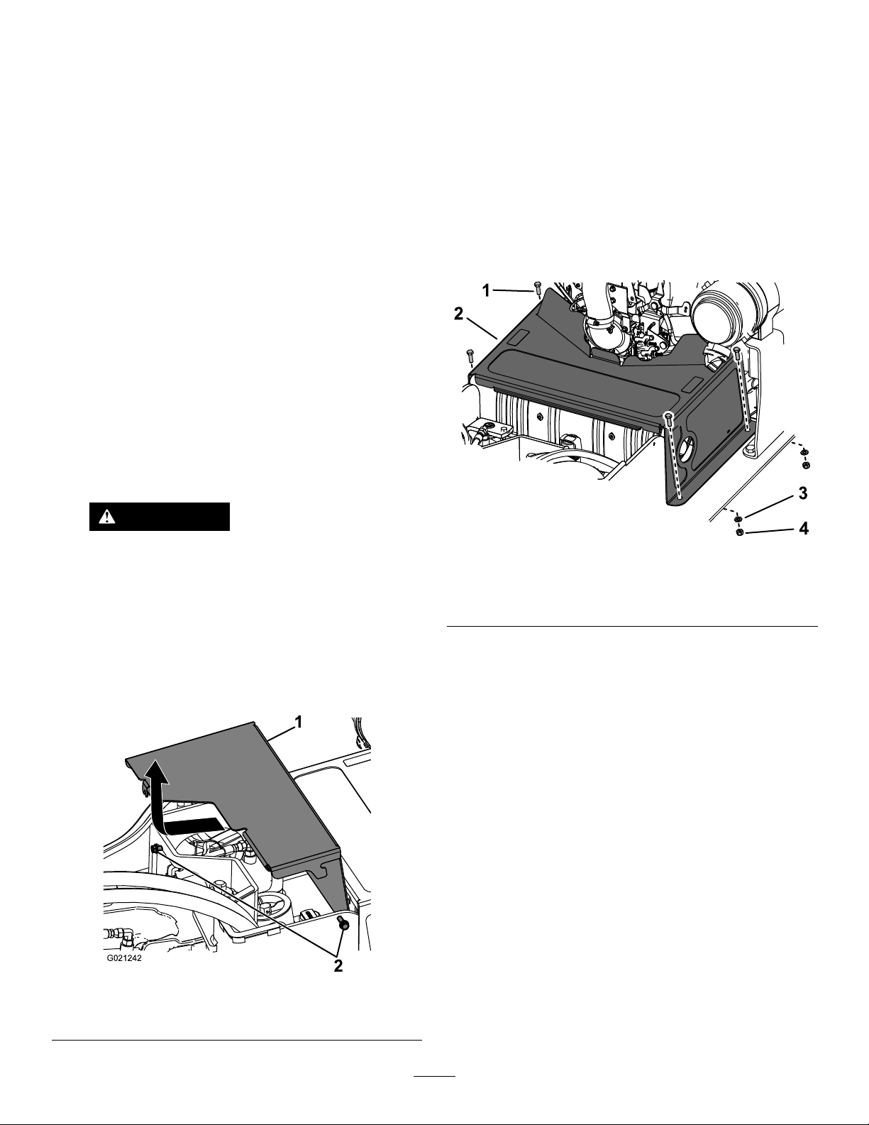
4.Slidethecoverforwardslightlyandpullupto
removethecover(Figure24).
Procedures
Important:Thefastenersonthecoversofthis
machinearedesignedtoremainonthecoverafter
removal.Loosenallfastenersoneachcoverafew
turnssothatthecoverisloosebutstillattached,
thengobackandloosenthemuntilthecover
comesfree.Thispreventsyoufromaccidentally
strippingtheboltsfreeoftheretainers.
RemovingtheFrontCover
Important:Thefastenersonthecoversofthis
machinearedesignedtoremainonthecoverafter
removal.Loosenallfastenersoneachcoverafew
turnssothatthecoverisloosebutstillattached,
thengobackandloosenthemuntilthecover
comesfree.Thispreventsyoufromaccidentally
strippingtheboltsfreeoftheretainers.
1.Parkthemachineonalevelsurface,engagethe
parkingbrake,andlowerthehydrauliclift.
2.Shutofftheengine,removethekey,andallow
theenginetocool.
5.Toinstallthefrontcover,slidethefrontcoverinto
placeandtightenthe2boltsthatyouloosened
previously(Figure24).
RemovingtheMuferCover
1.Removethefrontcover;refertoRemovingthe
FrontCover(page21).
2.Removethe4bolts,4washers,and4nuts
securingthemufercover.
WARNING
Ifthemachinehasbeenrunning,both
thecoverandthemuferunderthecover
willbehotandcancausesevereburns
ifyoutouchthem.
Allowthemachinetocoolbefore
removingthecover.
3.Loosenthe2boltssecuringthefrontcoverto
themachine(Figure24).
g250400
Figure25
1.Bolt(4)3.Washer(4)
2.Mufercover4.Nut(4)
3.Removethemufercover.
g021242
Figure24
1.Cover
2.Bolts
21
Page 22
RemovingtheBottom Shield
Lubrication
Important:Thefastenersonthecoversofthis
machinearedesignedtoremainonthecoverafter
removal.Loosenallfastenersoneachcoverafew
turnssothatthecoverisloosebutstillattached,
thengobackandloosenthemuntilthecover
comesfree.Thispreventsyoufromaccidentally
strippingtheboltsfreeoftheretainers.
1.Parkthemachineonalevelsurface,engage
theparkingbrake(ifapplicable),andlowerthe
hydrauliclift.
2.Shutofftheengineandremovethekey.
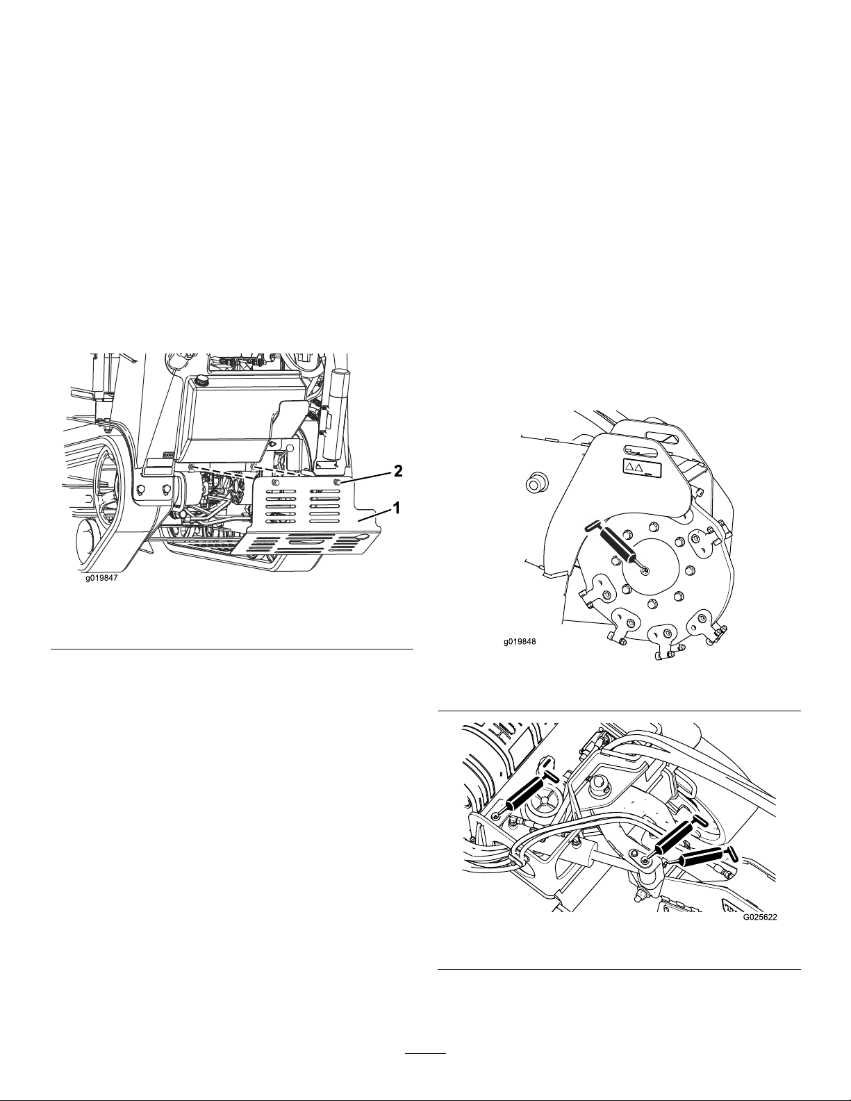
3.Loosenthe2boltssecuringthebottomshield
sequentiallyuntiltheshieldisfree(Figure26).
GreasingtheMachine
ServiceInterval:Beforeeachuseordaily(Greaseit
immediatelyaftereverywashing.)
GreaseType:General-purposegrease
1.Parkthemachineonalevelsurface,engagethe
parkingbrake,andlowerthehydrauliclift.
2.Shutofftheengineandremovethekey.
3.Cleanthegreasettingswitharag.
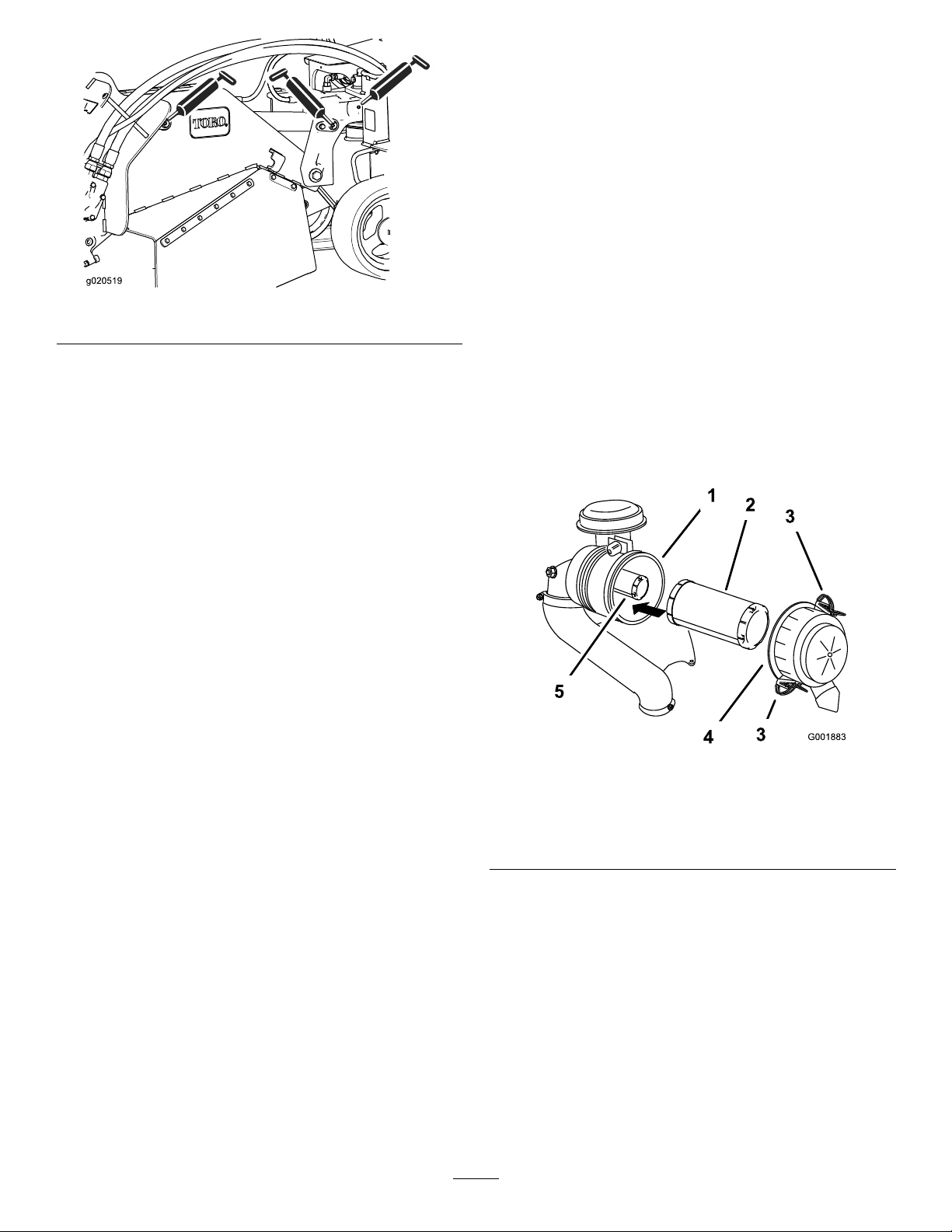
4.Connectagreaseguntoeachtting(Figure27
throughFigure29).
5.Pumpgreaseintothettingsuntilgreasebegins
tooozeoutofthebearings(approximately3
pumps).
6.Wipeupanyexcessgrease.
Figure26
1.Bottomshield2.Bolts
4.Pulltheshieldbackandoutofthemachine.
5.Toinstalltheshieldbeforeoperatingthe
machine,slidethebottomshieldintothe
machinesothatitrestsonall4tabsandsecure
itwiththe2boltsyouloosenedpreviously
(Figure26).
Note:Youmayneedtoliftuponthebottom
shieldtoensurethatitrestsonthefronttabs.
g019847
g019848
Figure27
g025622
Figure28
22
Page 23
EngineMaintenance
ServicingtheAirCleaner
ServiceInterval:Every150hours—Inspectthe
primarylter.
Every300hours—Replacetheprimaryairlter
(moreoftenindustyorsandyconditions).
Every300hours—Checktheinnerairlter.
Every600hours—Replacetheinnerairlter.
Figure29
g020519
RemovingtheFilters
1.Parkthemachineonalevelsurface,engage
theparkingbrake(ifapplicable),andlowerthe
hydrauliclift.
2.Shutofftheengineandremovethekey.
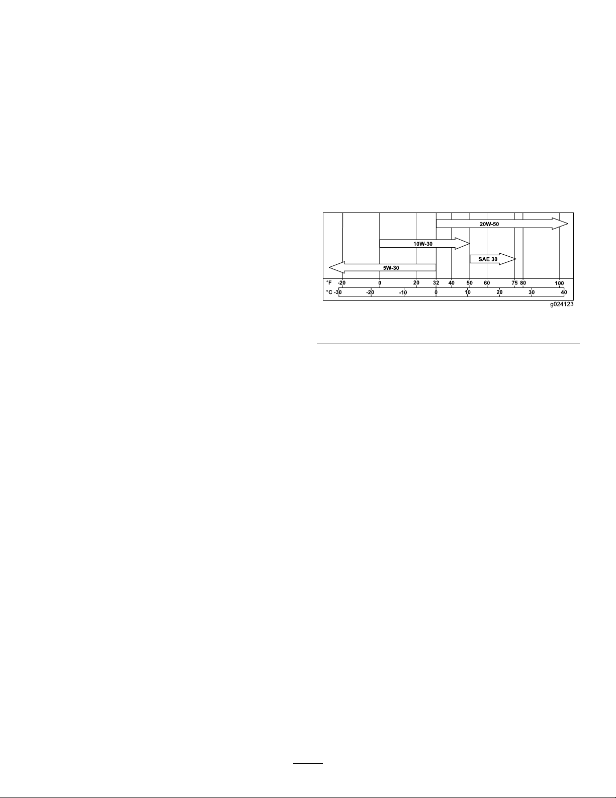
3.Releasethelatchesontheaircleanerandpull
theair-cleanercoverofftheair-cleanerbody
(Figure30).
Figure30
1.Air-cleanerbody4.Air-cleanercover
2.Primarylter5.Safetylter
3.Latch
4.Cleantheinsideoftheair-cleanercoverwith
compressedair.
5.Gentlyslidetheprimarylteroutofthe
air-cleanerbody(Figure30).
Note:Avoidknockingthelterintothesideof
thebody.
6.Removethesafetylteronlyifyouintendto
replaceit.
Important:Donotattempttocleanthe
safetylter.Ifthesafetylterisdirty,then
theprimarylterisdamaged.Replaceboth
lters.
23
g001883
Page 24
ServicingthePrimaryFilter
ServicingtheEngineOil
Inspecttheprimarylterfordamagebylookinginto
thelterwhileshiningabrightlightontheoutsideof
thelter.
Note:Holesinthelterappearasbrightspots.If
thelterisdirty,bent,ordamaged,replaceit.Donot
cleantheprimarylter.
ServicingtheSafetyFilter
Replacethesafetylter;nevercleanit.
Important:Donotattempttocleanthesafety
lter.Ifthesafetylterisdirty,thentheprimary
lterisdamaged.Replacebothlters.
InstallingtheFilters
Important:Topreventenginedamage,always
operatetheenginewithbothairltersandthe
coverinstalled.
1.Ifyouareinstallingnewlters,checkeachlter
forshippingdamage.
ServiceInterval:Beforeeachuseordaily
Every100hours/Yearly(whichevercomesrst)
Every200hours
Engine-OilSpecications
OilT ype:Detergentoil(APIserviceclassSJor
higher)
OilCapacity:withalterchange,1.9L(64oz)
Viscosity:Seethetablebelow.
g024123
Figure31
Note:Donotuseadamagedlter.
2.Ifyouarereplacingthesafetylter,carefully
slideitintothelterbody(Figure30).
3.Carefullyslidetheprimarylteroverthesafety
lter(Figure30).
Note:Ensurethattheprimarylterisfully
seatedbypushingonitsouterrimwhileinstalling
it.
Important:Donotpressonthesoftinside
areaofthelter.
4.Installtheair-cleanercoverwiththeside
indicatedasupfacingupwardandsecurethe
latches(Figure30).
Note:Syntheticoilsprovidebetterstartinginextreme
coldbelow-23°C(-10°F).
CheckingtheEngine-OilLevel
1.Parkthemachineonalevelsurface,engage
theparkingbrake(ifapplicable),andlowerthe
hydrauliclift.
2.Shutofftheengineandremovethekey.
24
Page 25
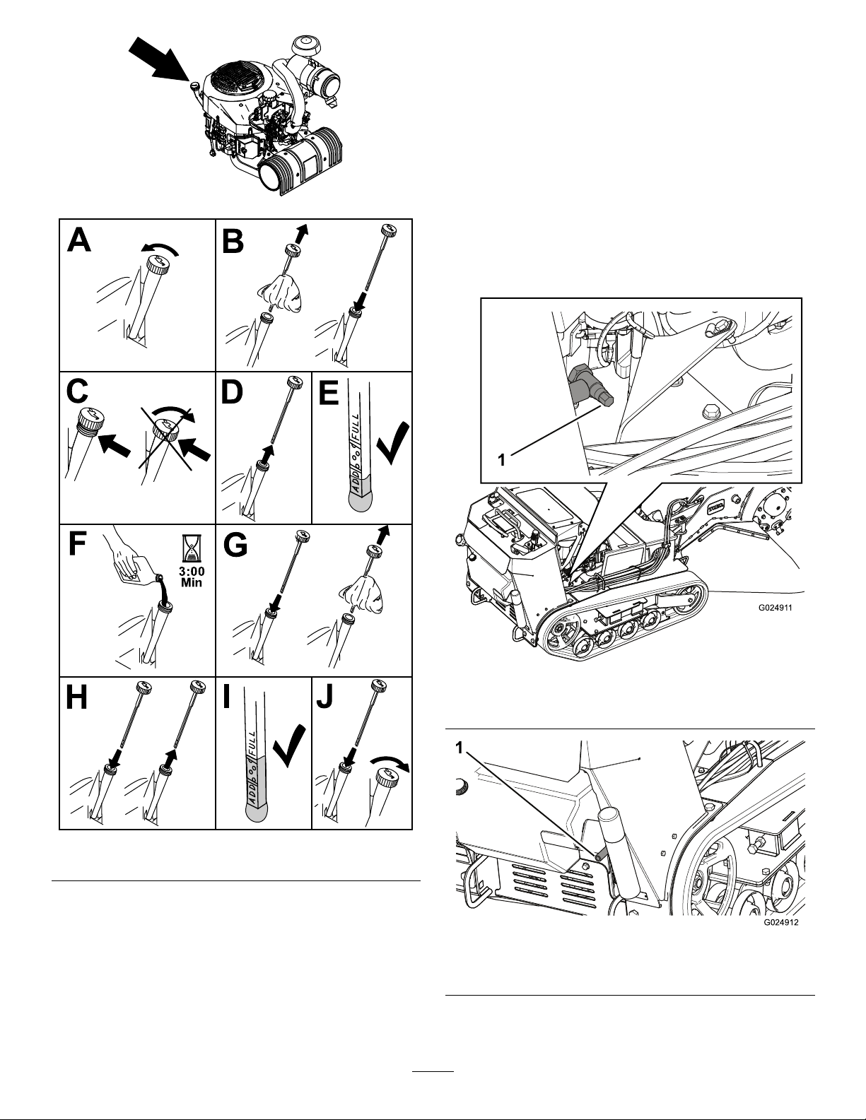
ChangingtheEngineOil
Note:Disposeoftheusedoilatarecyclingcenter.
1.Starttheengineandletitrun5minutes.
Note:Thiswarmstheoilsothatitdrainsbetter.
2.Parkthemachinesothattherearisslightlylower
thanthefronttoensuretheoildrainscompletely.
3.Engagetheparkingbrakeandlowerthe
g247313
hydrauliclift.
4.Shutofftheengineandremovethekey.
5.Placeapanbelowthedrainhose.Rotatetheoil
drainvalvetoallowoiltodrain(Figure33and
Figure34).
Figure32
g024911
Figure33
1.Oil-drainvalve
g194611
g024912
Figure34
1.Oil-drainhose
6.Whenoilhasdrainedcompletely,closethedrain
valve.
25
Page 26
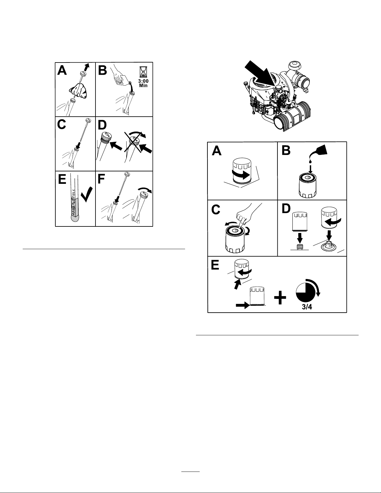
7.Disposeoftheusedoilatarecyclingcenter
8.Slowlypourapproximately80%ofthespecied
oilintothellertubeandslowlyaddthe
additionaloiltobringittotheFullmark(Figure
35).
ChangingtheEngine-OilFilter
1.Draintheoilfromtheengine;refertoChanging
theEngineOil(page25).
2.Changetheengine-oillter(Figure36).
g247314
Figure35
9.Starttheengineanddrivetoaatarea.Check
theoillevelagain.
g194610
g247326
Figure36
Note:Ensurethattheoil-ltergaskettouches
theengine,andthenturntheoillteranextra
3/4turn.
3.Fillthecrankcasewiththepropertypeofnew
oil;refertoEngine-OilSpecications(page24).
26
Page 27
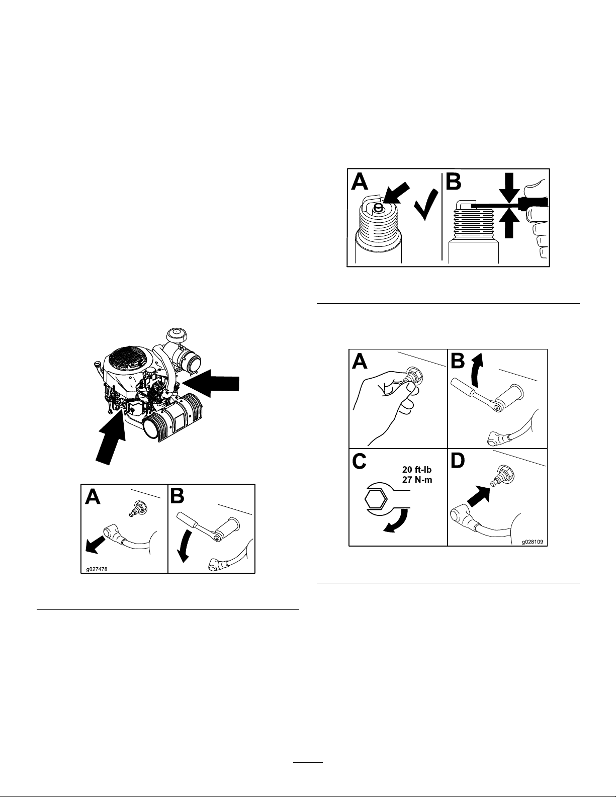
ServicingtheSparkPlug(s)
CheckingtheSparkPlug(s)
ServiceInterval:Every500hours/Yearly(whichever
comesrst)
Makesurethattheairgapbetweenthecenterand
sideelectrodesiscorrectbeforeinstallingthespark
plug.Useasparkplugwrenchforremovingand
installingthesparkplug(s)andagappingtool/feeler
gaugetocheckandadjusttheairgap.Installnew
sparkplug(s)ifnecessary.
Type:Champion
®
XC10YCorequivalent
AirGap:0.76mm(0.030inch)
RemovingtheSparkPlug(s)
1.Parkthemachineonalevelsurface,engage
theparkingbrake(ifapplicable),andlowerthe
hydrauliclift.
2.Shutofftheengineandremovethekey.
3.Locateandremovethesparkplug(s)asshown
inFigure37.
Important:Donotcleanthesparkplug(s).
Alwaysreplacethesparkplug(s)whenithas:a
blackcoating,wornelectrodes,anoilylm,or
cracks.
Ifyouseelightbrownorgrayontheinsulator,the
engineisoperatingproperly.Ablackcoatingonthe
insulatorusuallymeanstheaircleanerisdirty .
Setthegapto0.75mm(0.03inch).
g206628
Figure38
InstallingtheSparkPlug(s)
Figure37
g247337
g028109
Figure39
g027478
27
Page 28

FuelSystem
7.Openthefuel-shutoffvalveandallowthefuelto
drainintoafuelcanordrainpan.
Maintenance
DrainingtheFuelTank
DANGER
Incertainconditions,fuelisextremely
ammableandhighlyexplosive.Areor
explosionfromfuelcanburnyouandothers
andcandamageproperty.
RefertoFuelSafety(page4)foracomplete
listoffuelrelatedprecautions.
1.Parkthemachineonalevelsurface,engagethe
parkingbrake,andlowerthehydrauliclift.
2.Shutofftheengineandremovethekey.
3.Removethebottomshieldtoaccessthe
fuel-shutoffvalve;refertoRemovingtheBottom
Shield(page22).
Note:Thefuel-shutoffvalveisalsoaccessible
throughtheframe,behindthebattery(Figure
40).
Note:Ifdesired,youcanreplacethefuellter
atthistime;refertoReplacingtheHydraulic
Filter(page38).
8.Installthefuellineontothefuel-shutoffvalve.
Slidethehoseclampclosetothevalvetosecure
thefuelline.
9.Installthebottomshield;refertoRemovingthe
BottomShield(page22).
10.Wipeupanyspilledfuel.
Replacingthe Low-pressureFuelFilter
ServiceInterval:Every150hours/Yearly(whichever
comesrst)(moreoftenindirtyor
dustyconditions).
Neverinstalladirtylterifitisremovedfromthefuel
line.
Note:Notehowthefuellterisinstalledinorderto
installthenewltercorrectly.
Note:Wipeupanyspilledfuel.
Figure40
1.Fuel-shutoffvalve
4.Turnthefuel-shutoffvalvetotheclosedposition
(Figure41).
Figure41
1.Fuel-shutoffvalve
5.Squeezetheendsofthehoseclamponthe
enginesideofthevalvetogetherandslideitup
thefuellineawayfromthevalve(Figure41).
6.Pullthefuellineoffthevalve(Figure41).
1.Parkthemachineonalevelsurface,engagethe
parkingbrake,andlowerthehydrauliclift.
2.Shutofftheengineandremovethekey.
3.Turnthefuel-shutoffvalvetotheclosedposition.
g025624
g025625
4.Squeezetheendsofthehoseclampstogether
andslidethemawayfromthelter(Figure42).
Figure42
1.Fuellter
2.Hoseclamp
3.Fuelline
g008963
28
Page 29

5.Removethelterfromthefuellines.
6.Installanewlterandmovethehoseclamps
closetothelter.
7.Turnthefuel-shutoffvalvetotheopenposition.
ElectricalSystem
Maintenance
8.Checkforfuelleaksandrepairifneeded.
9.Wipeupanyspilledfuel.
Servicingthe High-PressureFuelFilter
Donotattempttoservicethehigh-pressurefuel
lter.Thehigh-pressurelterisintegratedwithin
thefuel-pumpmodule.Thefuellterandother
componentsinsidethefuel-pumpmodulearenot
serviceable.
Important:Donotattempttoopenthefuel-pump
module.
EnsurethatanAuthorizedServiceDealerreplaces
thefuel-pumpmodulewiththehigh-pressurefuellter.
ServicingtheBattery
ServiceInterval:Every25hours—Checkthebattery
electrolytelevel.
Alwayskeepthebatterycleanandfullycharged.Use
apapertoweltocleanthebatterycase.Ifthebattery
terminalsarecorroded,cleanthemwithasolutionof
4partswaterand1partbakingsoda.Applyalight
coatingofgreasetothebatteryterminalstoreduce
corrosion.
Voltage:12Vwith350A(coldcranking)at-18°C
(0ºF).
WARNING
Incorrectbatterycableroutingcoulddamage
themachineandcables,causingsparks.
Sparkscancausethebatterygassesto
explode,resultinginpersonalinjury.
•Alwaysdisconnectthenegative(black)
cablebeforedisconnectingthepositive
(red)cable.
•Alwaysconnectthepositive(red)cable
beforeconnectingthenegative(black)
cable.
WARNING
Batteryterminalsormetaltoolscouldshort
againstmetalcomponents,causingsparks.
Sparkscancausethebatterygassesto
explode,resultinginpersonalinjury.
•Whenremovingorinstallingthebattery,
donotallowthebatteryterminalstotouch
anymetalpartsofthetractionunit.
•Donotallowmetaltoolstoshortbetween
thebatteryterminalsandmetalpartsofthe
tractionunit.
29
Page 30

RemovingtheBattery
1.Parkthemachineonalevelsurface,engagethe
parkingbrake,andlowerthehydrauliclift.
2.Shutofftheengineandremovethekey.
3.Lifttheblackrubbercoveronthenegativecable.
Disconnectthenegativebatterycablefromthe
negative(-)batteryterminal(Figure43).
Figure43
ChargingtheBattery
WARNING
Chargingthebatteryproducesgassesthat
canexplode.
Neversmokenearthebatteryandkeepsparks
andamesawayfrombattery .
Important:Alwayskeepthebatteryfullycharged
(1.265specicgravity).Thisisespecially
importanttopreventbatterydamagewhenthe
temperatureisbelow0°C(32°F).
1.Removethebatteryfromthemachine;referto
RemovingtheBattery(page30).
2.Chargethebatteryatarateof3to4Afor4
to8hours(Figure44).Donotoverchargethe
battery.
g020521
1.Negativecable(rubber
covershownon)
2.Positivecable(rubber
covershownoff)
3.Batteryhold-downplate
4.Battery
5.J-bolt
4.Slidetheredterminalbootoffthepositive(red)
batteryterminal.Thenremovethepositive(red)
batterycable(Figure43).
5.Removetheholddownplate,j-bolts,and
locknutssecuringthebattery(Figure43)and
removethebattery.
Figure44
1.Positivebatterypost
2.Negativebatterypost
3.Red(+)chargerlead
4.Black(-)chargerlead
3.Whenthebatteryisfullycharged,unplug
thechargerfromtheelectricaloutlet,then
disconnectthechargerleadsfromthebattery
posts(Figure44).
g003792
30
Page 31
CleaningtheBattery
ReplacingtheFuses
Note:Keeptheterminalsandtheentirebatterycase
clean,becauseadirtybatterydischargesslowly.
1.Parkthemachineonalevelsurface,engagethe
parkingbrake,andlowerthehydrauliclift.
2.Shutofftheengineandremovethekey.
3.Removethebatteryfromthemachine;
RemovingtheBattery(page30).
4.Washtheentirecasewithasolutionofbaking
sodaandwater.
5.Rinsethebatterywithclearwater.
6.Coatthebatterypostsandcableconnectorswith
Grafo112X(skin-over)grease(ToroPartNo.
505-47)orpetroleumjellytopreventcorrosion.
7.Installthebattery;refertoInstallingtheBattery
(page31).
InstallingtheBattery
1.Usingthefastenerspreviouslyremoved,install
thepositive(red)batterycabletothepositive(+)
batteryterminal(Figure44).
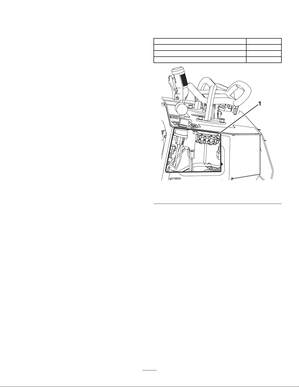
Thereare4fusesintheelectricalsystem.Theyare
underthecontrolpanelontheleftside(Figure45).
Startcircuit
Notused5A
Coolerfancircuit
Headlight(optional)
30A
20A
15A
2.Slidetheredterminalbootontothepositive
batterypost.
3.Usingthefastenerspreviouslyremoved,install
thenegative(black)batterycabletothenegative
(-)batteryterminal(Figure44).
4.Securethebatteryusingthebarandwingnuts
(Figure44).
Important:Ensurethatthebatterycablesdonot
contactanysharpedgesoreachother.
ServicingaReplacementBattery
Theoriginalbatteryismaintenance-freeanddoesnot
requireservice.Forservicingareplacementbattery,
refertothebatterymanufacturer’sinstructions.
g019854
Figure45
1.Fuseblock
31
Page 32
DriveSystem
Maintenance
ServicingtheTracks
CleaningtheTracks
ServiceInterval:Beforeeachuseordaily
Checkthetracksforexcessivewearandcleanthem
periodically.Ifthetracksareworn,replacethem.
1.Parkthemachineonalevelsurface,engagethe
parkingbrake,andlowerthehydrauliclift.
2.Shutofftheengineandremovethekey.
3.Usingawaterhoseorpressurewasher,remove
dirtfromeachtracksystem.
Important:Ensurethatyouusehigh-pressure
watertowashonlythetrackarea.Donotuse
ahigh-pressurewashertocleantherestofthe
machine.High-pressurewashingcandamagethe
electricalsystemandhydraulicvalvesordeplete
grease.
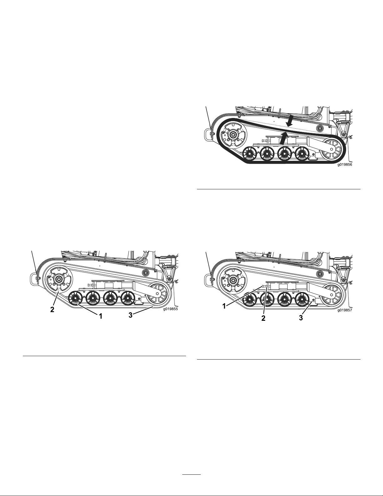
Important:Ensurethatyoufullycleantheroad
wheelsandthedrivewheel(Figure46).Theroad
wheelsshouldrotatefreelywhenclean.
CheckingandAdjustingtheTrack Tension
ServiceInterval:Aftertherst50hours
Every100hours
Tocheckthetensionofeachtrack,place20.4kg(45
lb)onthetrackmidwaybetweenthefrontroadwheel
andthedrivewheel.Thetrackshouldexnomore
than0.6to1cm(1/4to3/8inch).Ifitdoes,adjustthe
tracktensionusingthefollowingprocedure:
g019856
Figure47
1.Parkthemachineonalevelsurface,engagethe
parkingbrake,andlowerthehydrauliclift.
2.Shutofftheengineandremovethekey.
3.Loosenthejamnutonthetracktensioningbolt
andtheclampboltsonthetensionarm(Figure
48).
Figure46
1.Roadwheels3.Track
2.Drivewheel
g019855
Figure48
1.Tensioningbolt
2.Jamnut
4.Torquethetensioningboltto32.5to40N∙m(24
to30ft-lb)totightenthetrack(Figure48).
5.Ensurethatthetrackdeectslessthan0.6to1
cm(1/4to3/8inch)when20.6kg(45lb)offorce
isappliedtothetrackspan.Adjustthetorqueon
thetensioningboltasneeded.
6.Tightenthejamnut.
7.Tightentheclampboltsandtorqueto102N∙m
(75ft-lb).
32
3.Clampbolts
g019857
Page 33
ReplacingtheTracks
CheckingandGreasingtheRoad
Whenthetracksarebadlyworn,replacethem.
1.Parkthemachineonalevelsurface,engagethe
parkingbrake,andlowerthehydrauliclift.
2.Shutofftheengineandremovethekey.
3.Lift/supportthesideoftheunittobeworkedon
sothatthetrackis7.6to10cm(3to4inches)
offtheground.
4.Backoutthetensioningboltandjamnut(Figure
48).
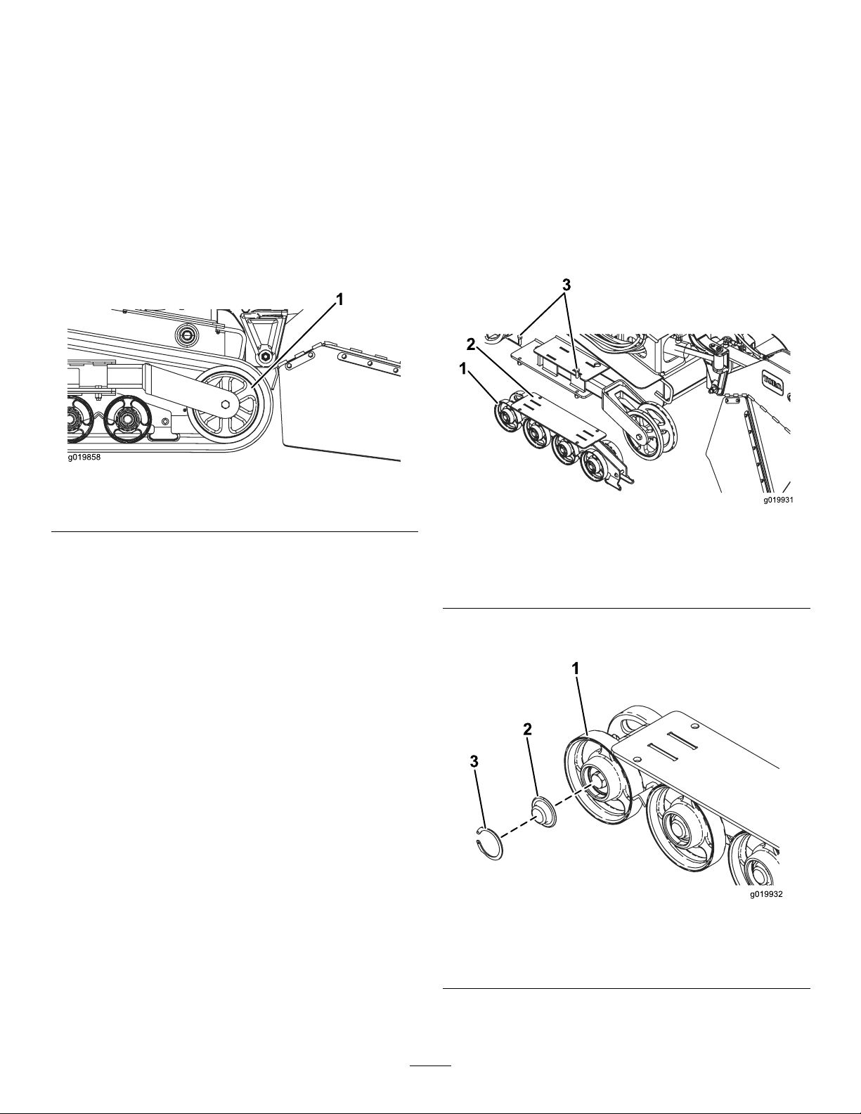
5.Pushthetensioningwheelrearwardasfarasit
willgo(Figure49).
Figure49
Wheels
ServiceInterval:Every250hours
1.Parkthemachineonalevelsurface,engagethe
parkingbrake,andlowerthehydrauliclift.
2.Shutofftheengineandremovethekey.
3.Removethetracks;refertoReplacingthe
Tracks(page33).
4.Removethe4boltssecuringeachlowertrack
guidewhichcontainstheroadwheels,and
removethem(Figure50).
g019858
1.Tensioningwheel
6.Beginremovingthetrackatthetopofthe
tensioningwheel,peelingitoffthewheelwhile
rotatingthetrackforward.
7.Whenthetrackisoffofthetensioningwheel,
removeitfromthemachine(Figure49).
8.Beginningatthedrivewheel,coilthenewtrack
aroundthewheel,ensuringthatthelugson
thetracktbetweenthespacersonthewheel
(Figure46).
9.Pushthetrackunderandbetweentherearand
centerroadwheels(Figure46).
10.Startingatthebottomofthetensioningwheel,
installthetrackaroundthewheelbyrotating
thetrackrearwardwhilepushingthelugsinto
thewheel.
11.Installthetensioningboltandjamnut.
12.T orquethetensioningboltto32.5to40N∙m(24
to30ft-lb)totightenthetrack.
13.Ensurethatthetrackdeectslessthan0.6to1
cm(1/4to3/8inch)when20.6kg(45lb)offorce
isappliedtothetrackspan.Adjustthetorqueon
thetensioningboltasneeded.
14.Tightenthejamnut.
15.Lowerthemachinetotheground.
16.Repeattheproceduretoreplacetheothertrack.
Figure50
1.Roadwheels
2.Lowertrackguide
3.Track-guidebolts(only2
shown)
5.Removethesnapringandcapfromaroad
wheel(Figure51).
Figure51
1.Roadwheel
2.Roadwheelcap
3.Snapring
6.Checkthegreaseunderthecapandaround
thegasket(Figure51).Ifitisdirty,gritty,or
g019931
g019932
33
Page 34
depleted,cleanoutallthegrease,replacethe
gasket,andaddnewgrease.
CoolingSystem
7.Ensurethattheroadwheelturnssmoothlyonthe
bearing.Ifitisfrozen,contactyourAuthorized
ServiceDealertoreplacetheroadwheel.
8.Placethegreasedroadwheelcapoverthebolt
head(Figure51).
9.Securetheroadwheelcapwiththesnapring
(Figure51).
10.Repeatsteps5through9forallroadwheels.
11.Installeachtrackguidetothetractionunitframe
usingthefastenersyouremovedpreviously.
Torquetheboltsto91to112N∙m(67to83ft-lb).
12.Installthetracks;refertoReplacingtheTracks
(page33).
Maintenance
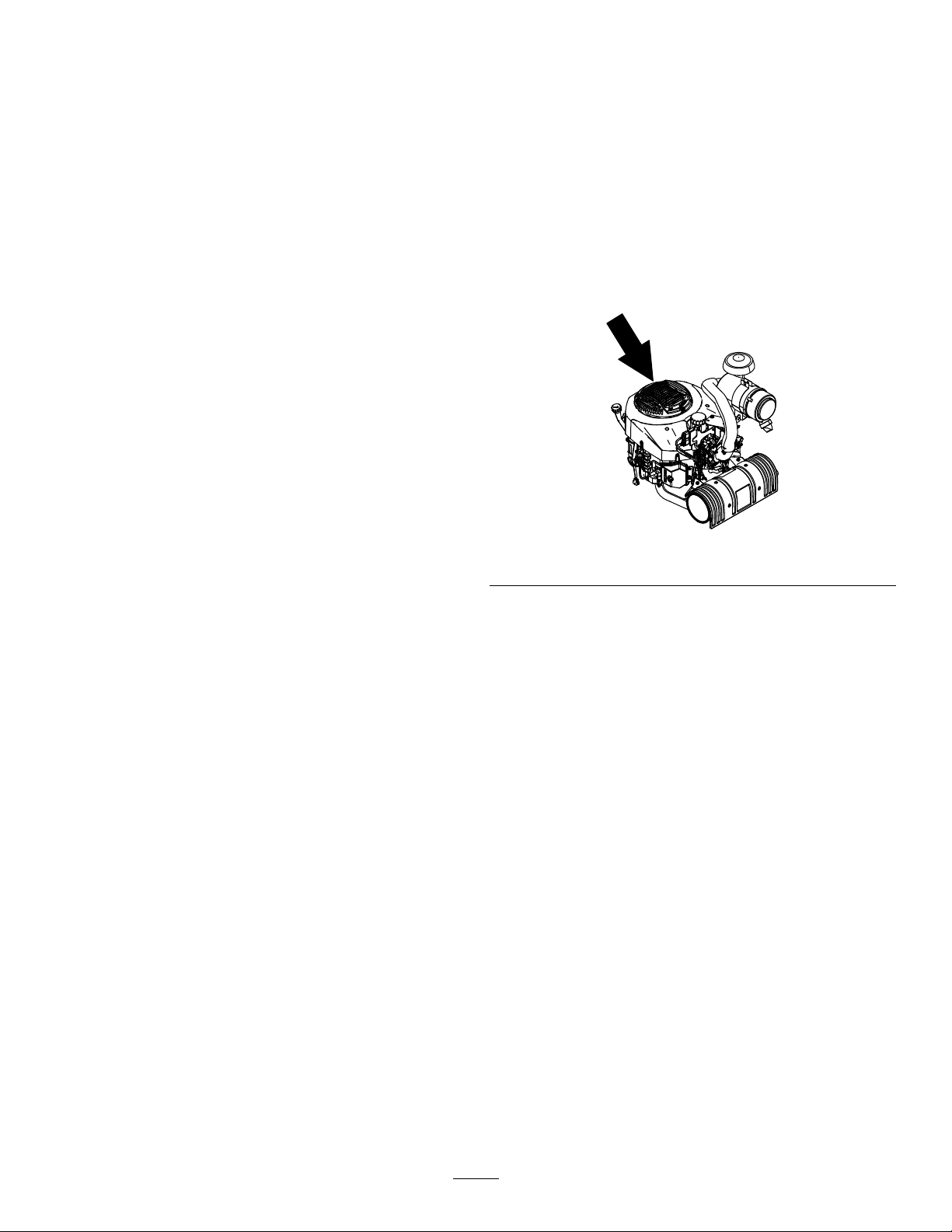
CleaningtheEngineScreen
ServiceInterval:Beforeeachuseordaily
Beforeeachuse,removeanybuildupofgrass,
dirt,orotherdebrisfromtheenginescreen.This
helpsensureadequatecoolingandcorrectengine
speedandreducesthepossibilityofoverheatingand
mechanicaldamagetotheengine.
g247684
Figure52
34
Page 35
BeltMaintenance
ReplacingthePump-Drive
ControlsSystem
Maintenance
Belt
Ifthepumpdrivebeltbeginstosquealoriscracked,
worn,orfrayed,replaceit.ContactyourAuthorized
ServiceDealerforareplacementbelt.
1.Parkthemachineonalevelsurface,engagethe
parkingbrake,andlowerthehydrauliclift.
2.Shutofftheengineandremovethekey.
3.Raisethebackofthemachineandsupportit
onjackstands.
4.Removethebottomshield;refertoRemoving
theBottomShield(page22).
5.Loosenthesetscrewonthepump-drivecoupler
(Figure53).
Adjustingthe Traction-ControlAlignment
Thefactoryadjuststhetractioncontrolsbefore
shippingthemachine.However,aftermanyhours
ofuse,youmayneedtoadjustthetraction-control
alignment,theneutralpositionofthetractioncontrol,
andthetrackingofthetractioncontrolinthefull
forwardposition.
Important:Toadjustthecontrolsproperly,
completeeachprocedureintheorderlisted.
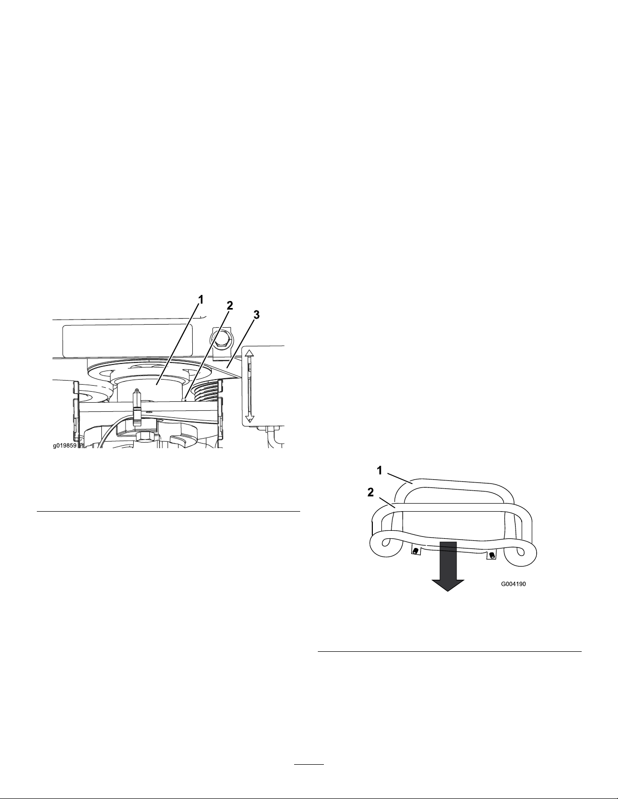
AdjustingtheTraction-Control ReversePosition
Ifthetractioncontrolbardoesnotrestushand
squarewiththereferencebarwheninthefull
reverseposition,immediatelycompletethefollowing
procedure:
1.Parkthemachineonalevelsurface,engage
theparkingbrake(ifapplicable),andlowerthe
hydrauliclift.
Figure53
1.Pump-drivecoupler3.Belt
2.Setscrew
6.Dropthecouplerdownawayfromthepulley.
7.Usingaspringpuller(availablefromyour
AuthorizedServiceDealer)orstiffmetalhook,
pulltheendoftheidlerpulleyspringoffthe
springbolttoreleasetensiononthebelt.
8.Removethebelt.
9.Routeanewbeltaroundthepulleys.
10.Installtheidlerpulleyspringonthebolt.
11.Pushthecoupleruptoengagethepulley .
12.Applythread-lockingcompoundtothecoupler
set-screwthreadsandtorqueitto10to12.6
N∙m(90to110in-lb).
13.Installthebottomshield.
2.Shutofftheengineandremovethekey.
3.Pullbackthetractioncontrolsothatthefrontof
thecontrolcontactsthereferencebar(Figure
g019859
54).
Figure54
1.Frontofthecontrol(outof
alignment)
4.Ifthefrontofthetractioncontroldoesnotrest
squareandushwiththereferencebar,loosen
thenutandboltinthestemofthetractioncontrol
(Figure55).
2.Referencebar
g004190
35
Page 36

Figure55
g004191
1.Tractioncontrol
2.Stem,bolt,andnut
5.Adjustthetractioncontrolsothatitrestsush
againstthereferencebarwhenitispulled
straightback(Figure55andFigure56).
Figure56
6.Tightentheangenutandboltinthetraction
controlstem.
7.Starttheengine.
8.Drivethemachineinreversewiththetraction
controltighttothereferencebar.Ifthemachine
doesnotbackupstraight,completethefollowing
procedure:
A.Shutofftheengine
B.Liftandsupportthemachinesothatboth
tracksareoffthegroundandarefreetorun.
C.Loosentheangenutandboltinthestem
ofthetractioncontrol(Figure55).
D.Loosenthejamnutsonthetractionrods,
underthecontrolpanel(Figure57).
g011476
Figure57
1.Tractionrod2.Jamnut
E.Startthemachineandsetthethrottleto
aboutthe1/3openposition.
WARNING
Whenthemachineisrunning,you
g004192
couldbecaughtandinjuredin
movingpartsorburnedonhot
surfaces.
Stayawayfrompinchpoints,moving
parts,andhotsurfaceswhen
adjustingtherunningmachine.
F.Haveahelperholdthetractioncontroltight
tothereferencebarinreverse.
G.Adjustthelengthofthetractionrodsuntil
bothtracksarerunningatthesamespeed.
Note:Youcanalsoadjustthemaximum
reversespeedofthetracksatthistime.
H.Tightenthejamnuts.
I.Adjustthetractioncontrolsothatitrests
ushagainstthereferencebarwhenitis
pulledstraightback(Figure55andFigure
56).
J.Tightentheangenutandboltinthe
tractioncontrolstem.
K.Shutofftheengineandlowerthemachine
totheground.
L.Drivethemachineinfullreverse,checking
toseeifthemachinetracksstraight.Ifit
doesnot,notethedirectionthemachine
veers.Repeattheadjustmentsothatthe
machinetracksstraightinreverse.
36
Page 37
AdjustingtheTraction-Control NeutralPosition
Ifthemachinecreepsforwardorbackwardwhen
thetractioncontrolisinneutralandthemachineis
warm,youmayneedtoadjustthereturn-to-neutral
mechanismonthepumps;contactyourAuthorized
ServiceDealer.
AdjustingtheTraction-Control ForwardPosition
HydraulicSystem
Maintenance
WARNING
Hydraulicuidescapingunderpressurecan
penetrateskinandcauseinjury.Fluidinjected
intotheskinmustbesurgicallyremoved
withinafewhoursbyadoctorfamiliarwith
thisformofinjury;otherwise,gangrenemay
result.
Ifthemachinedoesnotdrivestraightwhenyouhold
thetractioncontrolforwardagainstthereferencebar,
completethefollowingprocedure:
1.Drivethemachinewiththetractioncontrol
againstthereferencebar,notingwhichdirection
themachineveers.
2.Releasethetractioncontrol.
3.Ifthemachineveerstotheleft,loosentheright
jamnutandadjustthetrackingsetscrewonthe
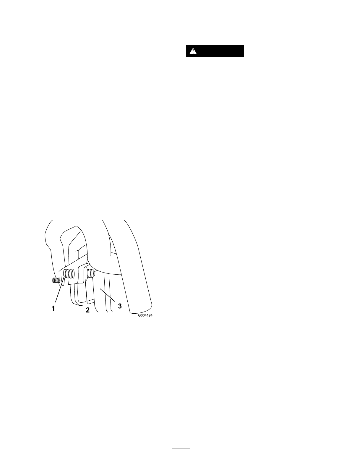
frontofthetractioncontrol(Figure58).
4.Ifthemachineveerstotheright,loosentheleft
jamnutandadjustthetrackingsetscrewonthe
frontofthetractioncontrol(Figure58).
g004194
Figure58
1.Setscrew3.Stop
2.Jamnut
5.Repeattheprocedureuntilthemachinedrives
straightinthefullforwardposition.
Important:Ensurethatthesetscrewstouch
thestopsinthefullforwardpositiontoavoid
overstrokingthehydraulicpumps.
•Keepyourbodyandhandsawayfrom
pinholeleaksornozzlesthateject
high-pressurehydraulicuid.
•Usecardboardorpapertondhydraulic
leaks;neveruseyourhands.
HydraulicFluid
Specications
HydraulicTankCapacity:38L(10USgallons)
UseToroPremiumAllSeasonHydraulicOil(refer
toyourAuthorizedT oroDealerformoreinformation).
Alternativeuids:IftheT orouidisnotavailable,
otherconventional,petroleum-baseduidsmay
beused,providedtheymeetallofthefollowing
materialpropertiesandindustryspecications.
Checkwithyouroilsuppliertoseewhetherthe
oilmeetsthesespecications.Note:Torowill
notassumeresponsibilityfordamagecausedby
impropersubstitutions,souseonlyproductsfrom
reputablemanufacturerswhowillstandbehindtheir
recommendation.
HighViscosityIndex/LowPourPointAnti-wearHydraulic
Fluid,ISOVG46
MaterialProperties:
Viscosity,ASTMD445cSt@40°C(104°F)44to48
ViscosityIndexASTM
D2270
PourPoint,ASTMD97-37°Cto-45°C(-34°Fto-49°F)
FZG,Failstage
Watercontent(new
uid):
IndustrySpecications:
VickersI-286-S,VickersM-2950-S,DenisonHF-0,Vickers
35VQ25(EatonATS373-C)
Theproperhydraulicuidsmustbespeciedfor
mobilemachinery(asopposedtoindustrialplant
usage),multi-weighttype,withZnDTPorZDDP
anti-wearadditivepackage(notanashless-typeuid).
cSt@100°C(212°F)7.9to9.1
140orhigher
11orbetter
500ppm(maximum)
Important:Manyhydraulicuidsarealmost
colorless,makingitdifculttospotleaks.A
reddyeadditiveforthehydraulicsystemoilis
availablein20ml(0.67oz)bottles.Onebottle
37
Page 38
issufcientfor15to22L(4to6USgallons)
ofhydraulicoil.OrderPart44-2500fromyour
AuthorizedServiceDealer.
Checkingthe
7.Installthecapandlteronthellerneckand
torqueboltontopto21to25N∙m(200to240
in-lb).
8.Installthecoverplate;refertoRemovingthe
FrontCover(page21).
Hydraulic-FluidLevel
ServiceInterval:Every25hours
RefertoHydraulicFluidSpecications(page37)for
hydraulicuidspecications.
1.Parkthemachineonalevelsurface,engage
theparkingbrake(ifapplicable),andlowerthe
hydrauliclift.
2.Shutofftheengineandremovethekey.
3.Lookintotheglassbubbleontherightsideof
themachine.Ifyoucannotseehydraulicuidin
thebubble,continuethisproceduretoadduid.
Figure59
1.Hydraulic-uidcheckbubble
4.Removethecoverplate;refertoRemovingthe
FrontCover(page21).
5.Cleantheareaaroundthellerneckofthe
hydraulictankandremovethecapandlter
fromthellerneckusingasocket(Figure60).
ReplacingtheHydraulic Filter
ServiceInterval:Every200hours
1.Parkthemachineonalevelsurface,engage
theparkingbrake(ifapplicable),andlowerthe
hydrauliclift.
2.Shutofftheengineandremovethekey.
3.Removethetopcover.
4.Removeanddiscardtheoldlter(Figure61).
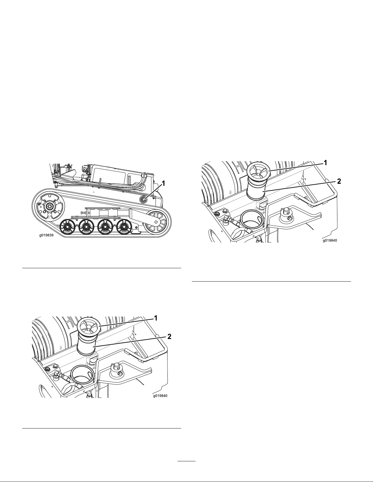
g019839
Figure61
1.Fillercap
2.Hydrauliclter
5.Installthereplacementhydrauliclterandller
cap(Figure61)andtorquetheboltontopto21
to25N∙m(200to240inch-lb).
6.Cleanupanyspilleduid.
7.Installthetopcover.
g019840
Figure60
1.Filler-neckcap
6.Ifthelevelislow,adduiduntilitisvisibleinthe
glassbubble.
2.Hydraulic-uidlter
ChangingtheHydraulic Fluid
ServiceInterval:Every400hours/Yearly(whichever
comesrst)
1.Parkthemachineonalevelsurface,engagethe
g019840
38
parkingbrake,andlowerthehydrauliclift.
2.Shutofftheengineandremovethekey.
3.Allowthemachinetocoolcompletely.
4.Removethetopcover.
5.Removethehydraulic-tankllercapandlter
(Figure61).
Page 39
6.Placeadrainpancapableofholding38L(10
USgallons)underthehydraulictank.
7.Removethehydraulictankdrainplugandallow
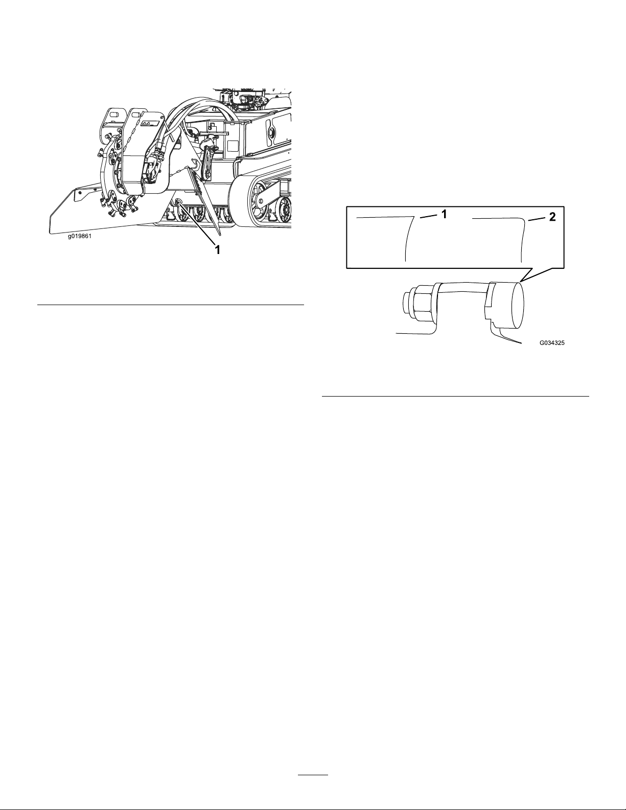
theuidtodrainintothepan(Figure62).
Figure62
1.Hydraulictankdrainplug
8.Whennished,installandtightenthedrainplug.
GrinderMaintenance
ReplacingtheTeeth
ServiceInterval:Beforeeachuseordaily—Check
theconditionoftheteeth;rotate
orreplaceanythatarewornor
damagedandtorquethenutsforall
teeth.
Duetothehighamountofwearplacedontheteeth,
youneedtorotateandreplacethemperiodically
(Figure63).
g019890
Note:Disposeoftheusedoilatacertied
recyclingcenter.
9.Fillthehydraulictankwithhydraulicuid;refer
toHydraulicFluidSpecications(page37).
10.Installthehydrauliclterandllercap(Figure
61)andtorqueboltontopto21to25N∙m(200
to240inch-lb).
11.Starttheengineandletitrunforafewminutes.
12.Shutofftheengine.
13.Checkthehydraulicuidlevelandtopitoffif
necessary;refertoCheckingtheHydraulic-Fluid
Level(page38).
14.Cleanupanyspilleduid.
15.Installthetopcover.
Figure63
1.Sharptooth
Eachtoothisindexedwith3positionssoyoucan
rotateittwice,exposinganewsharpedgebefore
replacingthetooth.T orotateatooth,loosenthenut
securingthetooth(Figure64).Pushthetoothforward
androtateitonethirdofaturn,bringinganunused
edgetotheoutside.T orquethenutsecuringthetooth
to37to45N∙m(27to33ft-lb).
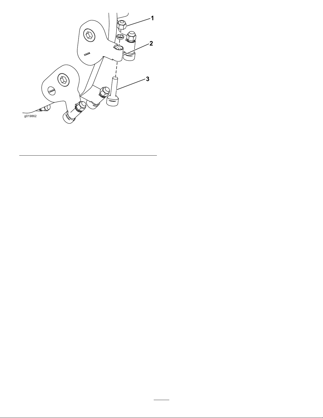
Toreplaceatooth,removethenutsecuringthetooth
toremoveit,theninstallanewtooth,spacer,and
nutinthesameposition(Figure64).T orquethenut
securingthetoothto37to45N∙m(27to33ft-lb).
2.Worntooth
g034325
39
Page 40
Cleaning
RemovingDebrisfromthe Machine
ServiceInterval:Aftereachuse
Important:Operatingtheenginewithblocked
screens,dirtyorpluggedcoolingns,and/or
coolingshroudsremovedwillresultinengine
damagefromoverheating.
1.Parkthemachineonalevelsurface,engage
theparkingbrake(ifapplicable),andlowerthe
hydrauliclift.
Figure64
1.Nut3.Tooth
2.Toothholder
g019862
2.Shutofftheengine,removethekey ,andwait
fortheenginetocool.
3.Wipeawaydebrisfromtheaircleaner.
4.Cleananydebrisbuildupontheengineand
muferwithabrushorblower.
Important:Itispreferabletoblowdirt
out,ratherthanwashingitout.Ifyouuse
water,keepitawayfromelectricalitemsand
hydraulicvalves.Donotuseahigh-pressure
washer.High-pressurewashingcandamage
theelectricalsystemandhydraulicvalvesor
depletegrease.
Note:RefertoRemovingtheMuferCover
(page21)toaccessthemufer.
5.Cleandebrisfromtheoilcooler.
40
Page 41

Storage
1.Parkthemachineonalevelsurface,engagethe
parkingbrake,andlowerthehydrauliclift.
2.Shutofftheengineandremovethekey.
3.Removedirtandgrimefromtheexternalpartsof
theentiremachine,especiallytheengine.Clean
dirtandchafffromtheoutsideoftheengine
cylinderheadnsandblowerhousing.
Important:Youcanwashthemachinewith
milddetergentandwater.Donotpressure
washthemachine.Avoidexcessiveuse
ofwater,especiallynearthecontrolpanel,
engine,hydraulicpumps,andmotors.
4.Servicetheaircleaner;refertoServicingtheAir
Cleaner(page23).
5.Greasethemachine;refertoGreasingthe
Machine(page22).
6.Changethecrankcaseoil;refertoChangingthe
EngineOil(page25).
7.Removethesparkplugandcheckthecondition
ofit;refertoServicingtheSparkPlug(s)(page
27).
9.Withthesparkplugremovedfromtheengine,
pour2tablespoonsofengineoilintothe
spark-plughole.
10.Placearagoverthespark-plugholetocatch
anyoilspray,thenusethestarterorrecoil
handletocranktheengineanddistributetheoil
insidethecylinder.
11.Installthesparkplug,butdonotinstallthewire
onthesparkplug.
12.Chargethebattery;refertoChargingtheBattery
(page30).
13.Checkandadjustthetracktension;referto
CheckingandAdjustingtheTrackTension(page
32).
14.Checkandtightenallfasteners.Repairor
replaceanypartthatisdamaged.
15.Paintallscratchedorbaremetalsurfaceswith
paintavailablefromyourAuthorizedService
Dealer.
16.Storethemachineinaclean,drygarageor
storagearea.Removethekeyfromtheignition
switchandkeepitinamemorableplace.
17.Coverthemachinetoprotectitandkeepitclean.
8.Forstorageover30days,preparethemachine
asfollows:
A.Addapetroleum-based
stabilizer/conditionertofuelinthe
tank.Followthemixinginstructionsfrom
thestabilizermanufacturer.Donotuse
analcohol-basedstabilizer(ethanolor
methanol).
Note:Afuelstabilizer/conditionerismost
effectivewhenitismixedwithfreshfueland
isusedatalltimes.
B.Runtheenginetodistributeconditionedfuel
throughthefuelsystemfor5minutes.
C.Shutofftheengine,allowittocool,and
drainthefueltankusingapumptype
syphon.
D.Starttheengineandrunituntilitshutsoff.
E.Engagethechoke.
F.Startandruntheengineuntilitdoesnot
startagain.
G.Disposeoffuelproperly.Recycleasper
localcodes.
Important:Donotstorefuelcontaining
stabilizer/conditionerlongerthanthe
durationrecommendedbythefuel-stabilizer
manufacturer.
41
Page 42

Troubleshooting
Problem
Thestarterdoesnotcrank.
Theenginedoesnotstart,startshard,or
failstokeeprunning.
Theenginelosespower.
PossibleCauseCorrectiveAction
1.Thebatteryisdischarged.
2.Theelectricalconnectionsare
corrodedorloose.
3.Therelayorswitchisdamaged.
1.Thefueltankisempty.1.Fillthetankwithfreshfuel.
2.Thefuel-shutoffvalveisclosed.2.Openthefuel-shutoffvalve.
3.Thecontrolsarenotinneutral.3.Movethecontrolstoneutral.
4.Theaircleanerisdirty.
5.Thespark-plugwireislooseor
disconnected.
6.Thesparkplugispitted,fouled,orthe
gapisincorrect.
7.Dirt,water,orstalefuelisinfuel
system.
1.Theengineloadisexcessive.1.Reducethegroundspeed.
2.Theaircleanerisdirty.
3.Theoillevelincrankcaseislow.
4.Thecoolingnsandairpassages
undertheengineblowerhousingare
plugged.
5.Thesparkplugispitted,fouled,orthe
gapisincorrect.
6.Dirt,water,orstalefuelisinfuel
system.
1.Chargethebatteryorreplaceit.
2.Checktheelectricalconnectionsfor
goodcontact.
3.ContactyourAuthorizedService
Dealer.
4.Cleanorreplacetheair-cleaner
elements.
5.Installthewireonthesparkplug.
6.Installanew,correctlygappedspark
plug.
7.ContactyourAuthorizedService
Dealer.
2.Cleanorreplacetheair-cleaner
elements.
3.Checkandaddoiltothecrankcase.
4.Removeanyobstructionsfromthe
coolingnsandairpassages.
5.Installanew,correctlygappedspark
plug.
6.ContactyourAuthorizedService
Dealer.
Theengineoverheats.
Thereisabnormalvibration.1.Theenginemountingboltsareloose.1.Tightentheenginemountingbolts.
Themachinedoesnotdrive.
Thegrinderdoesnotturn.
Thegrinderdoesnotcutfastenough.
1.Theengineloadisexcessive.1.Reducethegroundspeed.
2.Theoillevelincrankcaseislow.
3.Thecoolingnsandairpassages
undertheengineblowerhousingare
plugged.
1.Thehydraulic-uidlevelislow.1.Checkandaddhydraulicuid.
2.Thetowvalvesareopen.
3.Thehydraulicsystemisdamaged.
1.Achunkofwoodorarockiscaught
inthegrinder.
2.Thegrinderdrivesystemisdamaged.
3.Thehydraulicsystemisobstructed,
contaminated,ordamaged.
1.Theteethareworn.1.Rotateorreplacetheteeth.
2.Thehydraulicsystemisoverheated.
3.Thehydraulicsystemisobstructed,
contaminated,ordamaged.
2.Checkandaddoiltothecrankcase.
3.Removeanyobstructionsfromthe
coolingnsandairpassages.
2.Closethetowvalves.
3.ContactyourAuthorizedService
Dealer.
1.Shutofftheengineandremovethe
obstructionwithastick.
2.ContactyourAuthorizedService
Dealer.
3.
ContactyourAuthorizedService
Dealer.
2.Shutdownandallowthesystemto
cool.
3.
ContactyourAuthorizedService
Dealer.
42
Page 43

Problem
PossibleCauseCorrectiveAction
Thegrinderheaddoesnotlowerorraise.
Thehydraulicuidoverowsorisveryhot.1.Thecoolingfanisnotfunctioning.1.Checkthefuseandreplaceitif
1.Thelift/lowercontrolvalveisclosed.
1.Turnthecontroldialcounterclockwise
toopenit.
necessary.
43
Page 44
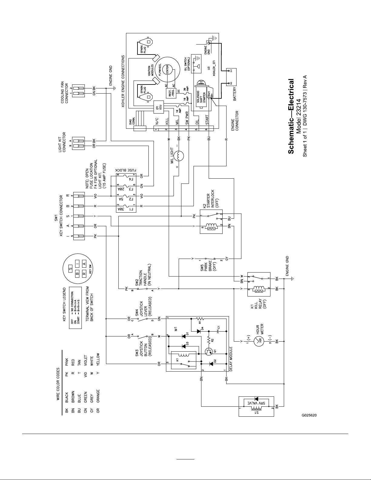
Schematics
ElectricalSchematic(Rev .A)
44
g025620
Page 45
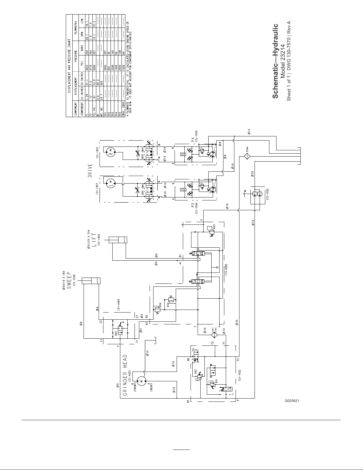
HydraulicSchematic(Rev .A)
45
g025621
Page 46

Notes:
Page 47

EuropeanPrivacyNotice
TheInformationT oroCollects
ToroWarrantyCompany(T oro)respectsyourprivacy.Inordertoprocessyourwarrantyclaimandcontactyouintheeventofaproductrecall,weaskyou
tosharecertainpersonalinformationwithus,eitherdirectlyorthroughyourlocalTorocompanyordealer.
TheT orowarrantysystemishostedonserverslocatedwithintheUnitedStateswhereprivacylawmaynotprovidethesameprotectionasapplies
inyourcountry.
BYSHARINGYOURPERSONALINFORMATIONWITHUS,YOUARECONSENTINGTOTHEPROCESSINGOFYOURPERSONALINFORMATION
ASDESCRIBEDINTHISPRIV ACYNOTICE.
TheWayT oroUsesInformation
Toromayuseyourpersonalinformationtoprocesswarrantyclaims,tocontactyouintheeventofaproductrecallandforanyotherpurposewhichwetell
youabout.ToromayshareyourinformationwithToro'safliates,dealersorotherbusinesspartnersinconnectionwithanyoftheseactivities.Wewillnot
sellyourpersonalinformationtoanyothercompany.Wereservetherighttodisclosepersonalinformationinordertocomplywithapplicablelawsand
withrequestsbytheappropriateauthorities,tooperateoursystemsproperlyorforourownprotectionorthatofotherusers.
RetentionofyourPersonalInformation
Wewillkeepyourpersonalinformationaslongasweneeditforthepurposesforwhichitwasoriginallycollectedorforotherlegitimatepurposes
(suchasregulatorycompliance),orasrequiredbyapplicablelaw .
Toro'sCommitmenttoSecurityofYourPersonalInformation
Wetakereasonableprecautionsinordertoprotectthesecurityofyourpersonalinformation.Wealsotakestepstomaintaintheaccuracyandcurrent
statusofpersonalinformation.
AccessandCorrectionofyourPersonalInformation
Ifyouwouldliketorevieworcorrectyourpersonalinformation,[email protected].
AustralianConsumerLaw
AustraliancustomerswillnddetailsrelatingtotheAustralianConsumerLaweitherinsidetheboxoratyourlocalT oroDealer.
374-0282RevC
Page 48

CaliforniaProposition65WarningInformation
Whatisthiswarning?
Youmayseeaproductforsalethathasawarninglabellikethefollowing:
WARNING:CancerandReproductiveHarm—www.p65Warnings.ca.gov.
WhatisProp65?
Prop65appliestoanycompanyoperatinginCalifornia,sellingproductsinCalifornia,ormanufacturingproductsthatmaybesoldinorbroughtinto
California.ItmandatesthattheGovernorofCaliforniamaintainandpublishalistofchemicalsknowntocausecancer,birthdefects,and/orother
reproductiveharm.Thelist,whichisupdatedannually,includeshundredsofchemicalsfoundinmanyeverydayitems.ThepurposeofProp65isto
informthepublicaboutexposuretothesechemicals.
Prop65doesnotbanthesaleofproductscontainingthesechemicalsbutinsteadrequireswarningsonanyproduct,productpackaging,orliteraturewith
theproduct.Moreover,aProp65warningdoesnotmeanthataproductisinviolationofanyproductsafetystandardsorrequirements.Infact,the
CaliforniagovernmenthasclariedthataProp65warning“isnotthesameasaregulatorydecisionthataproductis‘safe’or‘unsafe.’”Manyofthese
chemicalshavebeenusedineverydayproductsforyearswithoutdocumentedharm.Formoreinformation,gotohttps://oag.ca.gov/prop65/faqs-view-all
AProp65warningmeansthatacompanyhaseither(1)evaluatedtheexposureandhasconcludedthatitexceedsthe“nosignicantrisklevel”;or(2)
haschosentoprovideawarningbasedonitsunderstandingaboutthepresenceofalistedchemicalwithoutattemptingtoevaluatetheexposure.
Doesthislawapplyeverywhere?
Prop65warningsarerequiredunderCalifornialawonly.ThesewarningsareseenthroughoutCaliforniainawiderangeofsettings,includingbutnot
limitedtorestaurants,grocerystores,hotels,schools,andhospitals,andonawidevarietyofproducts.Additionally,someonlineandmailorder
retailersprovideProp65warningsontheirwebsitesorincatalogs.
.
HowdotheCaliforniawarningscomparetofederallimits?
Prop65standardsareoftenmorestringentthanfederalandinternationalstandards.TherearevarioussubstancesthatrequireaProp65warning
atlevelsthatarefarlowerthanfederalactionlimits.Forexample,theProp65standardforwarningsforleadis0.5μg/day,whichiswellbelow
thefederalandinternationalstandards.
Whydon’tallsimilarproductscarrythewarning?
•ProductssoldinCaliforniarequireProp65labellingwhilesimilarproductssoldelsewheredonot.
•AcompanyinvolvedinaProp65lawsuitreachingasettlementmayberequiredtouseProp65warningsforitsproducts,butothercompanies
makingsimilarproductsmayhavenosuchrequirement.
•TheenforcementofProp65isinconsistent.
•CompaniesmayelectnottoprovidewarningsbecausetheyconcludethattheyarenotrequiredtodosounderProp65;alackofwarningsfora
productdoesnotmeanthattheproductisfreeoflistedchemicalsatsimilarlevels.
WhydoesToroincludethiswarning?
Torohaschosentoprovideconsumerswithasmuchinformationaspossiblesothattheycanmakeinformeddecisionsabouttheproductstheybuyand
use.T oroprovideswarningsincertaincasesbasedonitsknowledgeofthepresenceofoneormorelistedchemicalswithoutevaluatingthelevelof
exposure,asnotallthelistedchemicalsprovideexposurelimitrequirements.WhiletheexposurefromT oroproductsmaybenegligibleorwellwithinthe
“nosignicantrisk”range,outofanabundanceofcaution,T orohaselectedtoprovidetheProp65warnings.Moreover,ifTorodoesnotprovidethese
warnings,itcouldbesuedbytheStateofCaliforniaorbyprivatepartiesseekingtoenforceProp65andsubjecttosubstantialpenalties.
RevA
 Loading...