

Page 1

FormNo.3377-818RevA
STX-38StumpGrinder
ModelNo.23212—SerialNo.313000001andUp
Registeratwww.T oro.com.
OriginalInstructions(EN)
*3377-818*A
Page 2

WARNING
Introduction
CALIFORNIA
Proposition65Warning
Thisproductcontainsachemicalorchemicals
knowntotheStateofCaliforniatocausecancer,
birthdefects,orreproductiveharm.
Theengineexhaustfromthisproduct
containschemicalsknowntotheStateof
Californiatocausecancer,birthdefects,
orotherreproductiveharm.
Useofthisproductmaycauseexposureto
chemicalsknowntotheStateofCalifornia
tocausecancer,birthdefects,orother
reproductiveharm.
DANGER
Theremaybeburiedutilitylinesintheworkarea.
Ifyoudigintothem,youmaycauseashockor
explosion.
Havethepropertyorworkareamarkedforburied
linesanddonotdiginmarkedareas.Contactyour
localmarkingserviceorutilitycompanytohavethe
propertymarked(forexample,intheUnitedStates,
call811forthenationwidemarkingservice).
Thismachineisdesignedtogrindandremovetreestumps
andsurfaceroots.Itisnotintendedtocutrockoranyother
materialotherthanwoodandthesoilaroundastump.
Readthisinformationcarefullytolearnhowtooperateand
maintainyourproductproperlyandtoavoidinjuryand
productdamage.Youareresponsibleforoperatingthe
productproperlyandsafely .
YoumaycontactTorodirectlyatwww .Toro.comforproduct
andaccessoryinformation,helpndingadealer,ortoregister
yourproduct.
Wheneveryouneedservice,genuineToroparts,oradditional
information,contactanAuthorizedServiceDealerorToro
CustomerServiceandhavethemodelandserialnumbersof
yourproductready .Figure1illustratesthelocationofthe
modelandserialnumbersontheproduct.Writethenumbers
inthespaceprovided.
ThissparkignitionsystemcomplieswithCanadianICES-002.
Becauseinsomeareastherearelocal,state,orfederal
regulationsrequiringthatasparkarresterbeusedonthe
engineofthismachine,asparkarresterisavailableas
anoption.Ifyourequireasparkarrester,contactyour
AuthorizedToroServiceDealer.
GenuineTorosparkarrestersareapprovedbytheUSDA
ForestryService.
Important:ItisaviolationofCaliforniaPublic
ResourceCodeSection4442touseoroperatetheengine
onanyforest-covered,brush-covered,orgrass-covered
landwithoutasparkarrestermufermaintainedin
workingorder,ortheengineconstricted,equipped,and
maintainedforthepreventionofre.Otherstatesor
federalareasmayhavesimilarlaws.
Theenclosed
informationregardingtheUSEnvironmentalProtection
Agency(EPA)andtheCaliforniaEmissionControl
Regulationofemissionsystems,maintenance,and
warranty.Replacementsmaybeorderedthroughthe
enginemanufacturer.
Engine Owner's Man ual
issuppliedfor
Figure1
1.Modelandserialnumberplate
ModelNo.
SerialNo.
Thismanualidentiespotentialhazardsandhassafety
messagesidentiedbythesafetyalertsymbol(Figure2),
whichsignalsahazardthatmaycauseseriousinjuryordeath
ifyoudonotfollowtherecommendedprecautions.
©2013—TheToro®Company
8111LyndaleAvenueSouth
Bloomington,MN55420
Contactusatwww.T oro.com.
2
PrintedintheUSA.
AllRightsReserved
Page 3

Figure2
1.Safetyalertsymbol
Thismanualuses2wordstohighlightinformation.
Importantcallsattentiontospecialmechanicalinformation
andNoteemphasizesgeneralinformationworthyofspecial
attention.
Contents
Introduction..................................................................2
Safety...........................................................................4
SafeOperatingPractices...........................................4
SoundPressure......................................................6
SoundPower..........................................................6
Hand-ArmVibrationLevel.......................................6
SlopeIndicator.......................................................7
SafetyandInstructionalDecals.................................8
Setup...........................................................................11
CheckingFluidLevels.............................................11
ChargingtheBattery...............................................11
OpeningtheLiftValve............................................11
ProductOverview.........................................................11
Controls...............................................................11
Specications........................................................15
Attachments/Accessories........................................15
Operation....................................................................15
AddingFuel...........................................................15
CheckingtheEngineOilLevel.................................16
StartingandStoppingtheEngine..............................16
StoppingtheMachine.............................................17
MovingaNon-functioningMachine.........................17
GrindingaStump...................................................18
SecuringtheMachineforTransport..........................18
LiftingtheMachine................................................19
OperatingTips......................................................19
Maintenance.................................................................20
RecommendedMaintenanceSchedule(s)......................20
PremaintenanceProcedures........................................21
RemovingtheFrontCover......................................21
InstallingtheFrontCover........................................21
RemovingtheBottomShield...................................21
InstallingtheBottomShield.....................................21
Lubrication...............................................................22
GreasingtheMachine.............................................22
EngineMaintenance..................................................23
ServicingtheAirCleaner.........................................23
ServicingtheEngineOil..........................................23
ServicingtheSparkPlugs.........................................26
FuelSystemMaintenance...........................................27
DrainingtheFuelTank...........................................27
ReplacingtheFuelFilter..........................................27
ElectricalSystemMaintenance....................................28
ServicingtheBattery...............................................28
ReplacingtheFuses................................................30
DriveSystemMaintenance.........................................30
ServicingtheTracks................................................30
CoolingSystemMaintenance......................................32
ServicingtheEngineOilCooler...............................32
CleaningtheEngineScreen......................................33
BeltMaintenance......................................................33
ReplacingthePumpDriveBelt.................................33
ControlsSystemMaintenance.....................................34
AdjustingtheTractionControlAlignment.................34
AdjustingtheTractionControlNeutral
Position.............................................................35
AdjustingtheTrackingoftheTractionControl,
FullForwardPosition..........................................35
HydraulicSystemMaintenance....................................36
CheckingtheHydraulicFluidLevel...........................36
ReplacingtheHydraulicFilter..................................36
ChangingtheHydraulicFluid...................................36
CheckingtheHydraulicLines...................................37
GrinderMaintenance..................................................38
ReplacingtheTeeth................................................38
Cleaning...................................................................38
RemovingDebrisfromtheMachine..........................38
Storage........................................................................39
Troubleshooting...........................................................40
Schematics...................................................................41
3
Page 4

Safety
Improperuseormaintenancecanresultininjury.T o
reducethepotentialforinjury,complywiththesesafety
instructionsandalwayspayattentiontothesafety
alertsymbol,whichmeans:
Danger
withtheinstructionmayresultinpersonalinjuryor
death.
—personalsafetyinstruction.Failuretocomply
SafeOperatingPractices
Thisproductiscapableofamputatinghandsandfeet.Always
followallsafetyinstructionstoavoidseriousinjuryordeath.
WARNING
Engineexhaustcontainscarbonmonoxide,an
odorless,deadlypoisonthatcankillyou.
Donotruntheengineindoorsorinanenclosed
area.
Training
•ReadtheOperator'sManualandothertrainingmaterial.If
theoperator(s)ormechanic(s)cannotreadEnglish,itis
theowner'sresponsibilitytoexplainthismaterialtothem.
•Becomefamiliarwiththesafeoperationoftheequipment,
operatorcontrols,andsafetysigns.
•Alloperatorsandmechanicsshouldbetrained.The
ownerisresponsiblefortrainingtheusers.
•Neverletchildrenoruntrainedpeopleoperateorservice
theequipment.Localregulationsmayrestricttheageof
theoperator.
•Theowner/usercanpreventandisresponsiblefor
accidentsorinjuriesoccurringtohimselforherself,other
peopleorproperty.
Preparation
•Evaluatetheterraintodeterminewhataccessoriesand
attachmentsareneededtoproperlyandsafelyperform
thejob.Onlyuseaccessoriesandattachmentsapproved
bythemanufacturer.
•Wearappropriateclothingincludinghardhat,afull
faceshield,safetyglasses,longpants,safetyshoes,and
hearingprotection.Longhair,looseclothingorjewelry
maygettangledinmovingparts.
•Inspecttheareawheretheequipmentistobeusedand
removeallobjectssuchasrocks,toys,andwirewhichcan
bethrownbythemachine.
•Useextracarewhenhandlinggasolineandotherfuels.
Theyareammableandvaporsareexplosive.
–Useonlyanapprovedcontainer
–Neverremovethegascaporaddfuelwiththeengine
running.Allowtheenginetocoolbeforerefueling.
Donotsmoke.
Caution
,
W ar ning
,or
–Neverrefuelordrainthemachineindoors.
•Checkthattheoperatorpresencecontrols,safetyswitches,
andshieldsareattachedandfunctioningproperly.Donot
operateunlesstheyarefunctioningproperly.
Operation
•Neverrunanengineinanenclosedarea.
•Onlyoperateingoodlight,keepingawayfromholesand
hiddenhazards.
•Besurealldrivesareinneutralbeforestartingtheengine.
Onlystarttheenginefromtheoperator'sposition.
•Slowdownanduseextracareonhillsides.Besureto
travelintherecommendeddirectiononhillsides.Turf
conditionscanaffectthemachine'sstability.
•Slowdownandusecautionwhenmakingturnsandwhen
changingdirectionsonslopes.
•Neveroperatewiththeguardsnotsecurelyinplace.Be
sureallinterlocksareattached,adjustedproperly,and
functioningproperly.
•Donotchangetheenginegovernorsettingoroverspeed
theengine.
•Stoponlevelground,lowerthegrinder,disengagethe
hydraulics,andshutofftheenginebeforeleavingthe
operator'spositionforanyreason.
•Keephandsandfeetawayfromthemovinggrinderwheel
andteeth.
•Lookbehindanddownbeforebackinguptobesureof
aclearpath.
•Nevercarrypassengersandkeeppetsandbystanders
away.
•Slowdownandusecautionwhenmakingturnsand
crossingroadsandsidewalks.
•Donotoperatethemachineundertheinuenceof
alcoholordrugs.
•Usecarewhenloadingorunloadingthemachineintoa
trailerortruck.
•Usecarewhenapproachingblindcorners,shrubs,trees,
orotherobjectsthatmayobscurevision.
•Ensurethattheareaisclearofotherpeoplebefore
operatingthemachine.Stopthemachineifanyoneenters
thearea.
•Neverleavearunningmachineunattended.Alwayslower
thegrinder,stoptheengine,andremovethekeybefore
leaving.
•Neverjerkthecontrols;useasteadymotion.
•Watchfortrafcwhenoperatingnearorcrossing
roadways.
•Donottouchpartswhichmaybehotfromoperation.
Allowthemtocoolbeforeattemptingtomaintain,adjust,
orservice.
•Ensurethatyouoperatethemachineinareaswhere
therearenoobstaclesincloseproximitytotheoperator.
4
Page 5

Failuretomaintainadequatedistancefromtrees,walls,
andotherbarriersmayresultininjuryasthemachine
backsupduringoperationiftheoperatorisnotattentive
tothesurroundings.Onlyoperatetheunitinareaswhere
thereissufcientclearancefortheoperatortosafely
maneuvertheproduct.
•Beforegrinding,havetheareamarkedforunderground
utilities,anddonotgrindintothegroundinmarkedareas.
•Locatethepinchpointareasmarkedonthemachineand
keephandsandfeetawayfromtheseareas.
•Lightningcancausesevereinjuryordeath.Iflightning
isseenorthunderisheardinthearea,donotoperate
themachine;seekshelter.
SlopeOperation
Slopesareamajorfactorrelatedtoloss-of-controland
tip-overaccidents,whichcanresultinsevereinjuryordeath.
Allslopesrequireextracaution.
•Donotoperatethemachineonhillsidesorslopes
exceedingtheanglesrecommendedinthefollowingtable.
FrontFacing
Uphill
16°16°16°
Note:SeealsotheSlopeIndicator(page7).
•Operateupanddownslopeswiththefrontendof
themachineuphill.
•Removeobstaclessuchasrocks,treelimbs,etc.fromthe
workarea.Watchforholes,ruts,orbumps,asuneven
terraincouldoverturnthemachine.Tallgrasscanhide
obstacles.
•UseonlyToro-approvedaccessories.Accessoriescan
changethestabilityandtheoperatingcharacteristics
ofthemachine.Warrantymaybevoidedifusedwith
unapprovedaccessories.
•Keepallmovementsonslopesslowandgradual.Donot
makesuddenchangesinspeedordirection.
•Avoidstartingorstoppingonaslope.Ifthemachine
losestraction,proceedslowly,straightdowntheslope.
•Avoidturningonslopes.Ifyoumustturn,turnslowly
andkeeptheheavyendofthemachineuphill.
•Donotoperateneardrop-offs,ditches,orembankments.
Themachinecouldsuddenlyturnoverifatrackgoes
overtheedgeofaclifforditch,orifanedgecavesin.
•Donotoperateonwetgrass.Reducedtractioncould
causesliding.
•Donotparkthemachineonahillsideorslopewithout
loweringthegrindertothegroundandchockingthe
tracks.
RearFacingUphill
SideFacingUphill
MaintenanceandStorage
•Disengagethehydraulics,lowerthegrinder,stopthe
engine,andremovethekey.W aitforallmovementto
stopbeforeadjusting,cleaning,orrepairing.
•Cleandebrisfromthegrinder,drives,mufers,andengine
tohelppreventres.Cleanupoilorfuelspillage.
•Lettheenginecoolbeforestoringanddonotstorenear
ame.
•Donotstorefuelnearamesordrainindoors.
•Parkthemachineonlevelground.Neverallowuntrained
personneltoservicethemachine.
•Usejackstandstosupportcomponentswhenrequired.
•Carefullyreleasepressurefromcomponentswithstored
energy.
•Disconnectthebatteryorremovethesparkplugwires
beforemakinganyrepairs.Disconnectthenegative
terminalrstandthepositivelast.Reconnectpositive
rstandnegativelast.
•Keephandsandfeetawayfrommovingparts.Ifpossible,
donotmakeadjustmentswiththeenginerunning.
•Keepallpartsingoodworkingconditionandallhardware
tightened.Replaceallwornordamageddecals.
•Keepnutsandboltstight.Keepequipmentingood
condition.
•Nevertamperwithsafetydevices.
•Keepthemachinefreeofgrass,leaves,orotherdebris
build-up.Cleanupoilorfuelspillage.Allowthemachine
tocoolbeforestoring.
•Useextracarewhenhandlinggasolineandotherfuels.
Theyareammableandvaporsareexplosive.
–Useonlyanapprovedcontainer.
–Neverremovethegascaporaddfuelwhenthe
engineisrunning.Allowtheenginetocoolbefore
refueling.Donotsmoke.
–Neverrefuelthemachineindoors.
–Neverstorethemachineorfuelcontainerinside
wherethereisanopename,suchasnearawater
heaterorfurnace.
–Neverllacontainerwhileitisinsideavehicle,trunk,
pick-upbed,oranysurfaceotherthantheground.
–Keepcontainernozzleincontactwiththetankduring
lling.
•Stopandinspecttheequipmentifyoustrikeanobject.
Makeanynecessaryrepairsbeforerestarting.
•UseonlygenuineTororeplacementpartstoensurethat
originalstandardsaremaintained.
•Batterysafety:
–Chargebatteriesinanopen,wellventilatedarea,away
fromsparkandames.Unplugthechargerbefore
connectingordisconnectingitfromthebattery.Wear
protectiveclothinganduseinsulatedtools.
5
Page 6

–Batteryacidispoisonousandcancauseburns.Avoid
contactwithskin,eyes,andclothing.Protectyour
face,eyes,andclothingwhenworkingwithabattery.
–Batterygasescanexplode.Keepcigarettes,sparks
andamesawayfromthebattery.
•Keepyourbodyandhandsawayfrompinholeleaks
ornozzlesthatejecthighpressurehydraulicuid.Use
cardboardorpapertondhydraulicleaks;neveruse
yourhands.Hydraulicuidescapingunderpressurecan
penetrateskinandcauseinjuryrequiringsurgerywithina
fewhoursbyaqualiedsurgeonorgangrenemayresult.
SoundPressure
Thisunithasasoundpressurelevelattheoperator’searof91
dBA,whichincludesanUncertaintyValue(K)of1dBA.
Soundpressurelevelwasdeterminedaccordingtothe
proceduresoutlinedinENISO11201.
Thesoundpressurelevelwillvarydependingonconditions.
SoundPower
Thisunithasasoundpowerlevelof109dBA,whichincludes
anUncertaintyValue(K)of3.75dBA.
Thesoundpowerlevelwasdeterminedwithnoload
accordingtotheproceduresoutlinedinISO3744.
Hand-ArmVibrationLevel
DeclaredinaccordancewithEN12096
Measuredvibrationlevelforrighthand=2.2m/s
Measuredvibrationlevelforlefthand=2.3m/s
UncertaintyValue(K)=1.2m/s
Measuredvaluesweredeterminedaccordingtotheprocedures
outlinedinENISO20643.
2
2
2
6
Page 7
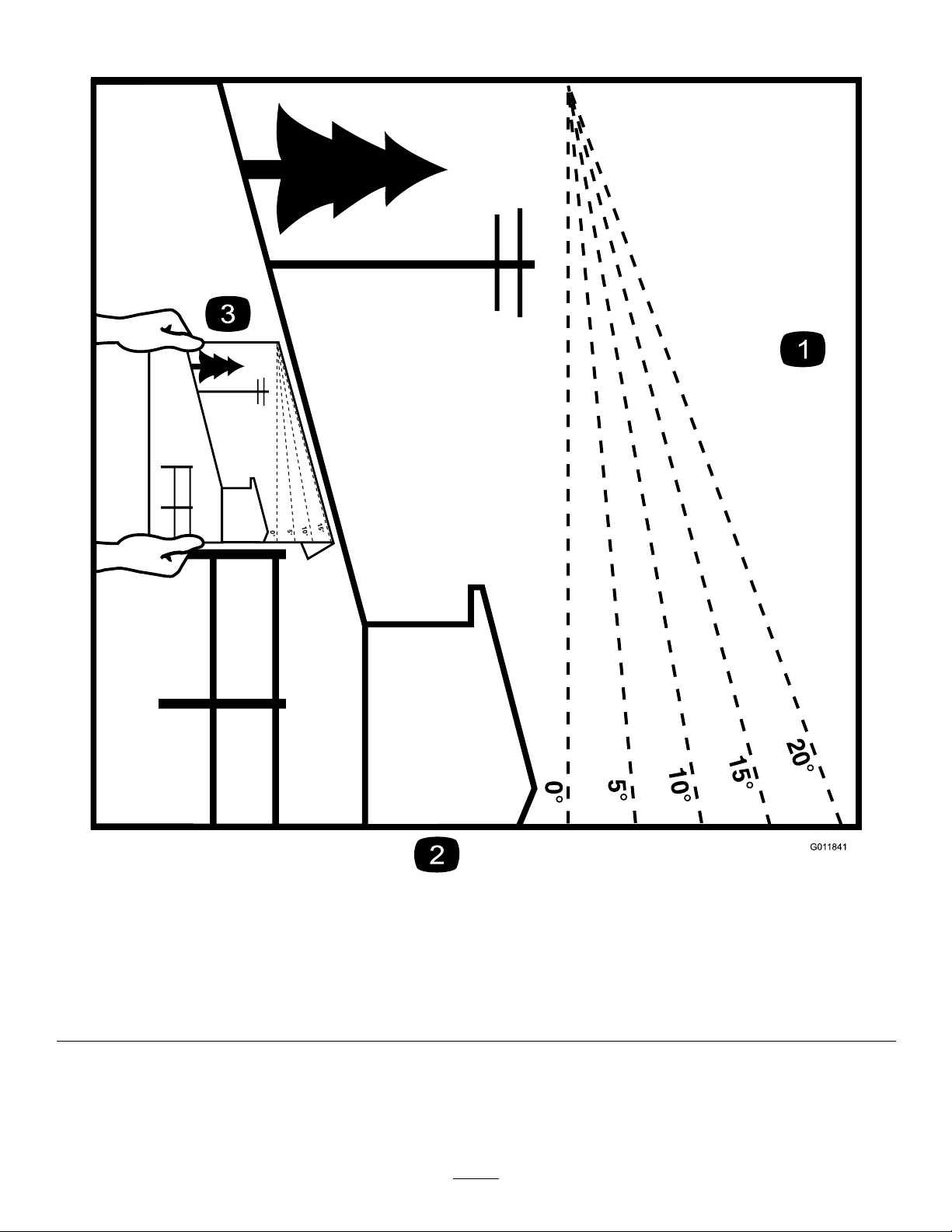
SlopeIndicator
G011841
Figure3
Thispagemaybecopiedforpersonaluse.
1.Todeterminethemaximumslopeyoucansafelyoperatethemachineon,refertoSlopeOperation(page5).Usetheslope
indicatortodeterminethedegreeofslopeofhillsbeforeoperating.Donotoperatethismachineonaslopegreaterthanthat
speciedinSlopeOperation(page5).Foldalongtheappropriatelinetomatchtherecommendedslope.
2.Alignthisedgewithaverticalsurface,atree,building,fencepole,etc.
3.Exampleofhowtocompareslopewithfoldededge.
7
Page 8

SafetyandInstructionalDecals
Safetydecalsandinstructionsareeasilyvisibletotheoperatorandarelocatednearanyareaofpotential
danger.Replaceanydecalthatisdamagedorlost.
93–6686
1.Hydraulicoil
2.ReadtheOperator's
Manual.
93-7321
1.Cutting/dismembermenthazardofhandsandfeet,rotating
knives/blades—stayawayfrommovingparts.
93-7814
1.Entanglementhazard,belt—stayawayfrommovingparts.
93-9363
1.Parkingbrake3.Unlocked
2.Locked
100-4650
1.Crushinghazardofhand—keepbystandersasafedistance
fromthemachine.
2.Crushinghazardoffoot—keepbystandersasafedistance
fromthemachine.
1.Liftpoint
93-9084
2.Tie-downpoint
107-9366
1.Thrownobjecthazard—keepbystandersasafedistance
fromthemachine.
115-2047
1.Warning—donottouchthehotsurface.
8
Page 9

115-4020
1.Turnright3.Reverse
2.Forward
4.Turnleft
121–4402
117–2718
BatterySymbols
Someorallofthesesymbolsareonyourbattery
1.Explosionhazard
2.Nore,opename,or
smoking.
3.Causticliquid/chemical
burnhazard
4.Weareyeprotection9.Flusheyesimmediately
5.ReadtheOperator's
Manual.
6.Keepbystandersasafe
7.Weareyeprotection;
8.Batteryacidcancause
10.Containslead;donot
distancefromthebattery .
explosivegasescan
causeblindnessandother
injuries
blindnessorsevereburns.
withwaterandgetmedical
helpfast.
discard.
1.Pushforwardtolowerthe
stumpgrinder
2.Moverighttomovethe
stumpgrindertotheright
1.Engine—start
2.Engine—run
3.Engine—stop
4.Fast
5.Engine—run
3.Pullbacktoraisethe
stumpgrinder
4.Movelefttomovethe
stumpgrindertotheleft
121–4381
6.Slow
7.On
8.Choke
9.Off
10.ReadtheOperator’s
Manualbeforestarting
theengine—1.Ensure
thetractioncontrolisin
Neutral;2.Movethe
throttletoFast,theChoke
toon,anddonottouchthe
joystick;3.Turnthekeyto
starttheengine.)
9
Page 10

119-4606
1.Warning—readtheOperator'sManual.
2.Cutting/dismembermenthazard;grinder—keepbystandersa
safedistancefromthemachine;donotoperatethegrinder
headwhiletransportingthemachine.
3.Warning—stayawayfrommovingparts;waitforallmoving
partstostop.
4.Warning—donotoperatethismachineunlessyouaretrained.
1.ReadtheOperator’sManualforinformationonoperatingthe
grinder—1)Grindhorizontallyalongtheedgeofthestump;2)
Lowerthegrinderslightlyintothestump;3)Grindhorizontally
downtogroundlevel;4)Movethegrinderforward.
2.Donotstartgrindinginthemiddleofthestump;startgrinding
attheedgeofthestump.
5.Explosionandelectricshockhazard—donotdiginareaswith
buriedutilitylines;contactlocalpowerorganizationsbefore
digging.
6.Tipping/crushinghazard—lowerthecutterheadwhen
operatingonslopes.
7.Explosionhazard,fueling—stoptheengineandextinguish
allameswhenfueling.
8.Warning—lowerthegrinderhead,settheparkingbrake(if
applicable),stoptheengine,removetheignitionkeybefore
leavingthemachine.
121–4382
3.1)Topowerthegrinder,pressthesafetylockandthetrigger
together;2)T okeepthegrinderrunning,holdthetrigger.
10
Page 11

Setup
CheckingFluidLevels
Beforestartingtheengineforthersttime,check
theengineoilandhydraulicuidlevels;referto
CheckingtheEngineOilLevel(page16)and
CheckingtheHydraulicFluidLevel(page36)formore
information.
ChargingtheBattery
Chargethebattery;refertoChargingtheBattery(page29)for
moreinformation.
ProductOverview
OpeningtheLiftValve
Beforeyoucanraisethegrinderandmovethemachine,
youmustopentheliftvalvelocatedunderthecontrolpanel
(Figure4).Turntheknobcounterclockwisetoallowyouto
liftthegrinder.Thefurtheryouturntheknobthefasterthe
headwillraiseandlowerwhenactivated.
Figure5
1.Controlpanel
2.Chipshield
3.Engine
4.Battery6.Track
5.Grinder
Controls
Becomefamiliarwithallthecontrols(Figure6)beforeyou
starttheengineandoperatethemachine.
Figure6
Figure4
1.Keyswitch
2.Throttlelever
3.Chokelever8.Grindercontrollever
4.Hourmeter9.Handle
5.Tractioncontrol
6.Referencebar
7.Reversesafetyplate
KeySwitch
Thekeyswitchhasthreepositions:off,run,andstart.
Tostarttheengine,rotatethekeytothestartposition.Release
thekeywhenenginestartsanditwillmoveautomaticallyto
therunposition.
Tostoptheengine,rotatethekeytotheoffposition.
11
Page 12
ThrottleLever
Movethecontrolforwardtoincreasetheenginespeedand
rearwardtodecreasespeed.
ChokeLever
Beforestartingacoldengine,movethechokeleverforward.
Aftertheenginestarts,regulatethechoketokeeptheengine
runningsmoothly.Assoonaspossible,movethechokelever
allthewayrearward.
Note:Awarmenginerequireslittleornochoking.
HourMeter
Whentheengineisoff,thehourmeterdisplaysthenumber
ofhoursofoperationthathavebeenloggedonthemachine.
ReferenceBar
Whendrivingthemachine,usethereferencebarasahandle
andaleveragepointforcontrollingthetractioncontrol.To
ensuresmooth,controlledoperation,donottakebothhands
offofthereferencebarwhileoperatingthemachine.
TractionControl
Figure8
1.Referencebar(doesnotmovetogiveyouareferencepoint
andaxedhandletoholdwhileoperatingthetractionunit)
2.Tractioncontrol(movestocontrolthemachine)
•Tomoveforward,movethetractioncontrolforward
(Figure9).
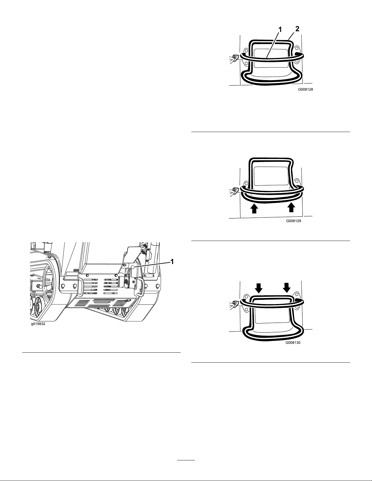
ParkingBrake
Toengagetheparkingbrake,lifttheleverupwards.To
disengagetheparkingbrake,pushtheleverdownwards.
Figure7
1.Parkingbrakelever
Figure9
•Tomoverearward,movethetractioncontrolrearward
(Figure10).Whenreversing,lookbehindfor
obstructionsandkeepyourhandsonthereference
bar(Figure8).
Figure10
•Toturnright,rotatethetractioncontrolclockwise
(Figure11).
12
Page 13
G008131
Figure11
G008132
•Toturnleft,rotatethetractioncontrolcounterclockwise
(Figure12).
Figure12
•Tostop,releasethetractioncontrol(Figure8).
Note:Thefartheryoumovethetractioncontrolinany
direction,thefasterthemachinewillmoveinthatdirection.
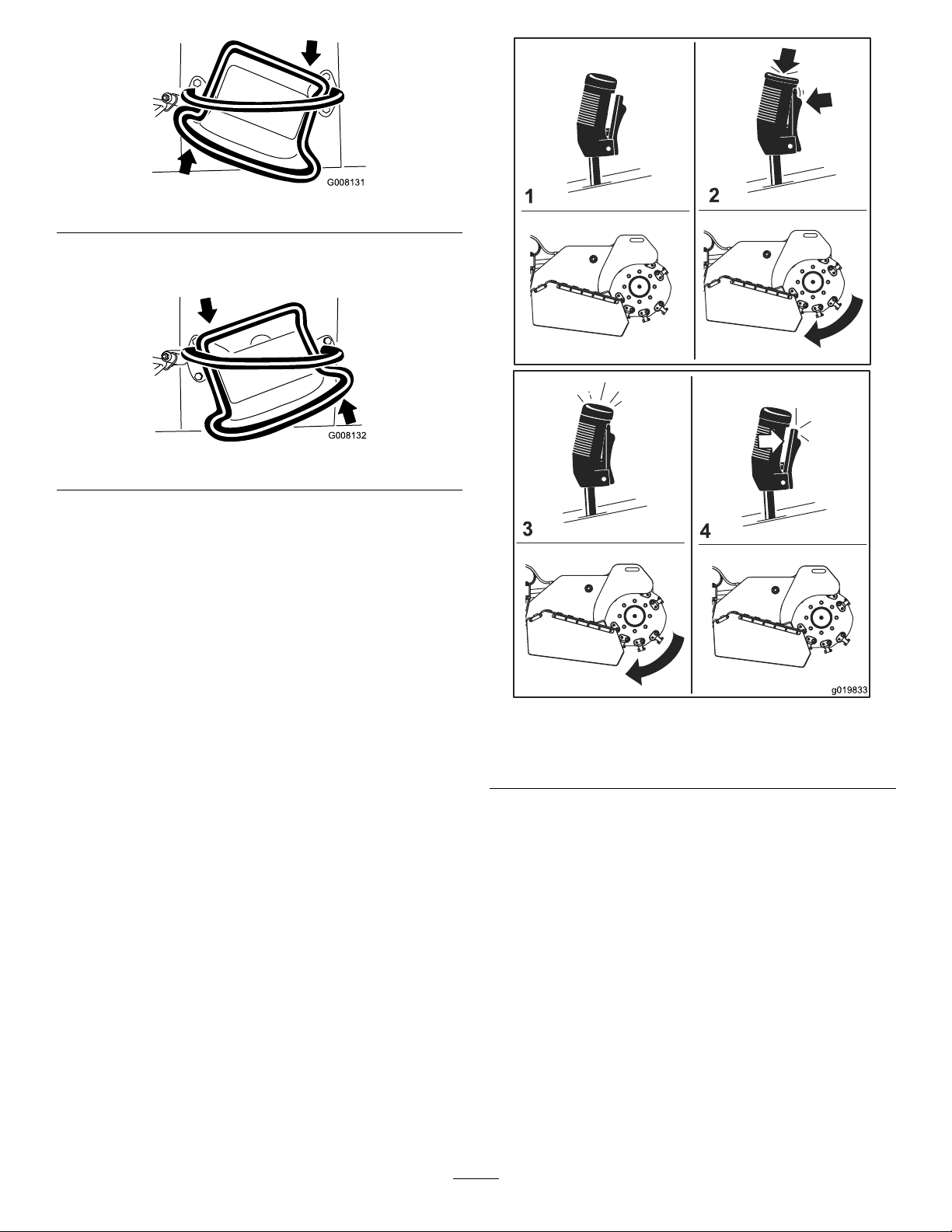
GrinderControlLever
Operatethegrinderusingthegrindercontrolleverasfollows:
•Tostartthegrinder(Figure13),presstheredbuttonon
thetopofthelever,thensqueezethetrigger.Oncethe
grinderhasstarted,youcanreleasetheredbutton.
•Tostopthegrinder(
morethanahalfsecond.
Note:Ifyouareoperatingthegrinderandmomentarily
releasethetrigger(i.e.,lessthanahalfsecond)thegrinder
willcontinueoperation.
Figure13),releasethetriggerfor
Figure13
1.Neutral3.Runthegrinder
2.Startthegrinder4.Stopthegrinder
•Toraisethegrinder,pullbackonthelever(Figure14).
13
Page 14
Figure14
Figure16
Lift/LowerSpeedControl
•Tolowerthegrinder,pushtheleverforward(Figure15).
Figure15
•Torotatethegrindertotherightorleft,movetheleverin
thedesireddirection.
Youcanchangethespeedthegrinderheadraisesandlowers
usingthelift/lowerspeedcontrol,locatedundertheright
sideofthecontrolpanel(Figure17).Rotatethedialcounter
clockwisetoincreasethespeedorclockwisetoreducethe
speed.
Ifyoueverneedtostopthemachinewiththegrinderhead
raised,turnthecontroldialallthewayclockwisetolockthe
grinderheadbeforeleavingthemachineorperformingany
maintenance
CAUTION
IfyouleavethegrinderheadintheUpposition
withoutturningthelift/lowerspeedcontroldialall
thewayclockwise,thegrindercouldlowercrushing
youorbystanders.
Wheneverpossible,lowerthegrindertotheground
beforestoppingtheengine.Ifyoumusthave
thegrinderheadraised,turnthelift/lowerspeed
controldialallthewayclockwisetolockthegrinder.
14
Page 15

Figure17
Specications
Note:Specicationsanddesignaresubjecttochange
withoutnotice.
Width
Length
Height
Weight
Attachments/Accessories
AselectionofToroapprovedattachmentsandaccessoriesis
availableforusewiththemachinetoenhanceandexpand
itscapabilities.ContactyourAuthorizedServiceDealeror
Distributororgotowww .T oro.comforalistofallapproved
attachmentsandaccessories.
86cm(34inches)
241cm(95inches)
130cm(51inches)
794kg(1750lb)
Operation
Note:Determinetheleftandrightsidesofthemachine
fromthenormaloperatingposition.
Important:Beforeoperating,checkthefuelandoil
level,andremovedebrisfromthemachine.Also,ensure
thattheareaisclearofpeopleanddebris.Y oushould
alsoknowandhavemarkedthelocationsofallutility
lines.
AddingFuel
Useunleadedgasoline(87pumpoctaneminimum).Leaded,
regulargasolinemaybeusedifunleadedisnotavailable.
DANGER
Incertainconditions,gasolineisextremely
ammableandhighlyexplosive.Areorexplosion
fromgasolinecanburnyouandothersandcan
damageproperty.
•Fillthefueltankoutdoors,inanopenarea,
whentheengineiscold.Wipeupanygasoline
thatspills.
•Neverllthefueltankinsideanenclosedtrailer.
•Donotllthefueltankcompletelyfull.Add
gasolinetothefueltankuntilthelevelis1/4to
1/2inch(6to13mm)belowthebottomofthe
llerneck.Thisemptyspaceinthetankallows
gasolinetoexpand.
•Neversmokewhenhandlinggasoline,andstay
awayfromanopenameorwheregasoline
fumesmaybeignitedbyaspark.
•Storegasolineinanapprovedcontainerand
keepitoutofthereachofchildren.Neverbuy
morethana30-daysupplyofgasoline.
•Donotoperatewithoutentireexhaustsystemin
placeandinproperworkingcondition.
15
Page 16

DANGER
Incertainconditionsduringfueling,static
electricitycanbereleasedcausingasparkwhich
canignitethegasolinevapors.Areorexplosion
fromgasolinecanburnyouandothersandcan
damageproperty.
•Alwaysplacegasolinecontainersontheground
awayfromyourvehiclebeforelling.
•Donotllgasolinecontainersinsideavehicleor
onatruckortrailerbedbecauseinteriorcarpets
orplastictruckbedlinersmayinsulatethe
containerandslowthelossofanystaticcharge.
•Whenpractical,removegas-poweredequipment
fromthetruckortrailerandrefueltheequipment
withitswheelsontheground.
•Ifthisisnotpossible,thenrefuelsuch
equipmentonatruckortrailerfromaportable
container,ratherthanfromagasolinedispenser
nozzle.
•Ifagasolinedispensernozzlemustbeused,
keepthenozzleincontactwiththerimofthe
fueltankorcontaineropeningatalltimesuntil
fuelingiscomplete.
Figure18
1.Fueltankcap2.Fuelgauge
4.Addunleadedgasolinetothefueltank,untilthelevelis
1/4to1/2inchbelowthebottomofthellerneck.
Important:Thisspaceinthetankallowsgasoline
toexpand.Donotllthefueltankcompletelyfull.
5.Installthefueltankcapsecurely.
6.Wipeupanygasolinethatmayhavespilled.
Important:Donotusemethanol,gasolinecontaining
methanol,orgasoholcontainingmorethan10%ethanol
becausethefuelsystemcouldbedamaged.Donotmix
oilwithgasoline.
UsingStabilizer/Conditioner
Useafuelstabilizer/conditionerinthemachinetokeep
gasolinefreshduringstorageof90daysorless.Forlonger
storageitisrecommendedthatthefueltankbedrained.
Important:Donotusefueladditivescontaining
methanolorethanol.
Addthecorrectamountofgasstabilizer/conditionertothe
gas.
Note:Afuelstabilizer/conditionerismosteffectivewhen
mixedwithfreshgasoline.Tominimizethechanceofvarnish
depositsinthefuelsystem,usefuelstabilizeratalltimes.
FillingtheFuelTank
1.Parkthemachineonalevelsurface,lowerthegrinder,
andstoptheengine.
CheckingtheEngineOilLevel
Beforeyoustarttheengineandusethemachine,
checktheoillevelintheenginecrankcase;referto
CheckingtheEngineOilLevel(page23).
StartingandStoppingthe Engine
StartingtheEngine
1.MovethethrottlelevermidwaybetweenSlowandFast
positions(Figure19).
2.Removethekeyandallowtheenginetocool.
3.Cleanaroundthefueltankcapandremoveit
(
Figure18).
16
Page 17

4.Removethekey .
StoppingtheMachine
Tostopthemachine,releasethetractioncontrol,movethe
throttlelevertoslow(turtle),lowerthegrindertotheground,
stoptheengine,andremovethekey.
CAUTION
Achildoruntrainedbystandercouldattemptto
operatethemachineandbeinjured.
Figure19
1.Throttlelever3.Key
2.Chokelever
2.MovethechokelevertotheOnposition(Figure19).
Note:Awarmorhotenginemaynotrequirechoking.
3.TurnthekeytotheOnposition(Figure19).Whenthe
enginestarts,releasethekey.
Important:Donotengagethestarterformore
than10secondsatatime.Iftheenginefailsto
start,allowa30secondcool-downperiodbetween
attempts.Failuretofollowtheseinstructionscan
burnoutthestartermotor.
4.GraduallymovethechokelevertotheOffposition
(
Figure19).Iftheenginestallsorhesitates,engagethe
chokeagainuntiltheenginewarmsup.
5.Movethethrottlelevertothedesiredsetting
(Figure19).
Important:Iftheengineisrunathighspeeds
whenthehydraulicsystemiscold(i.e.,whenthe
ambientairtemperatureisnearfreezingorlower),
hydraulicsystemdamagecouldoccur.When
startingtheengineincoldconditions,allowthe
enginetoruninthemiddlethrottlepositionfor
2to5minutesbeforemovingthethrottletofast
(rabbit).
Note:Iftheoutdoortemperatureisbelowfreezing,
storethemachineinagaragetokeepitwarmerand
aidinstarting.
StoppingtheEngine
1.Stopthegrinderandlowerittotheground.
Removethekeyfromtheswitchwhenleavingthe
machine,evenifjustforafewseconds.
MovingaNon-functioning Machine
Important:Donottoworpullthemachinewithoutrst
openingthetowvalves,orthehydraulicsystemwillbe
damaged.
1.Stoptheengine.
2.Removethebottomshield.
3.Usingawrench,turnthetowvalvesonthehydraulic
motorstwicecounter-clockwise(
Figure20
1.Towvalves
4.Installthebottomshieldandtowthemachineas
required.
5.Whenthemachinehasbeenrepaired,closethetow
valvesbeforeoperatingit.
Figure20).
2.MovethethrottlelevertotheSlowposition(Figure19).
3.Turnthekeyoff(
Note:Iftheenginehasbeenworkinghardorishot,
letitidleforaminutebeforeturningtheignitionkey
off.Thishelpscooltheenginebeforeitisstopped.In
anemergency,theenginemaybestoppedimmediately.
Figure19).
17
Page 18

GrindingaStump
DANGER
Thisproductiscapableofamputatinghandsand
feet.
•Stayintheoperator'spositionwhilethegrinder
isrunningandkeepawayfromthegrinder.
•Keepallbystandersasafedistancefromthe
grinder.
•Stopthegrinderimmediatelyifanypeopleor
animalsentertheworkarea.
WARNING
Grindingastumpwillthrowwoodchips,soil,and
otherdebrisintotheairwhichcouldinjureyouor
bystanders.
•Alwayswearahardhatandafullfaceshield
whenusingthegrinder.
•Keepallbystandersasafedistancefromthe
grinder.
WARNING
Thegrinderisveryloudwhencuttingastumpand
candamageyourears.
Alwayswearhearingprotectionwhenusingthe
grinder.
1.Starttheengine,raisethegrinder,setthethrottlelever
totheFastposition,andmovethemachinetothe
stumptobeground.
2.Usethegrindercontrolleverandthetractioncontrol
topositionthegrindertoonesideofthefrontof
thestump,aboutaninchbelowthetopofthestump
surface.
3.Startthegrinderandwaitforittogetuptofullspeed.
4.Usingthegrindercontrollever,swingthegrinder
slowlyacrossthefaceofthestump,cuttingawaya
swathofchips(Figure21).
Important:Thegrinderwillautomaticallyslow
downthespeedatwhichitswingsintothestump
tomaintaintheoptimumywheelspeedandnot
bogdowninthewood.
Figure21
5.Lowerthegrinderaboutaninchandswingitback
overthestump.
6.Repeatstep5untilyouhavereachedgroundlevel.
7.Raisethegrindersothatitisaboutaninchbelowthe
topoftheremainingstump,movethemachineforward
afewinchesandrepeatsteps4through6.
8.Repeatsteps4through7untilyouhavegroundoff
theentirestump.
9.Ifthereareanylargerootstobeground,positionthe
grinderovereachrootandusethetractioncontroland
grindercontroltomovethegrinderalongtheroot,
grindingitaway.
SecuringtheMachinefor Transport
Whentransportingthemachineonatrailer,alwaysusethe
followingprocedure:
Important:Donotoperateordrivethemachineon
roadways.
1.Stoptheengine.
2.Lowerthegrinder.
3.Securethemachinetothetrailerwithchainsorstraps
usingthetie-down/liftloopsatthefrontandrearof
themachine(Figure22andFigure23).Refertoyour
localordinancesfortrailerandtie-downrequirements.
18
Page 19

1.Fronttie-downloop
•Alwaysusefullthrottle(maximumenginespeed)when
grinding.
•Cuttheedgesofthestumpformoreefcientgrinding.
Onceyourcuttingswathiscloseto1/4ofthewheel
diameter(Figure21),liftthegrinder,moveforwardand
begincuttingontheedgeagain.
Figure22
Figure23
1.Reartie-downloops
LiftingtheMachine
Youcanliftthemachineusingthetie-down/liftloopsaslift
points(
Figure22andFigure23).
OperatingTips
•Cleantheareaoftrash,branchesandrocksbefore
operatingtopreventequipmentdamage.
19
Page 20

Maintenance
Note:Determinetheleftandrightsidesofthemachinefromthenormaloperatingposition.
RecommendedMaintenanceSchedule(s)
MaintenanceService
Interval
Aftertherst50hours
Beforeeachuseordaily
Aftereachuse
Every25hours
Every100hours
Every150hours
Every200hours
Every250hours
MaintenanceProcedure
•Checkandadjustthetracktension.
•Greasethemachine.(greaseimmediatelyaftereverywashing.)
•Checktheengineoillevel.
•Cleantheenginescreen.
•Checktheconditionoftheteethandrotateorreplaceanythatarewornordamaged.
•Removedebrisfromthemachine.
•Checkforloosefasteners.
•Checktheconditionofandcleanthetracks.
•Checkthebatteryelectrolytelevel.
•Checkthehydraulicuidlevel.
•Checkandadjustthetracktension.
•Checkthehydrauliclinesforleaks,loosettings,kinkedlines,loosemounting
supports,wear,weather,andchemicaldeteriorationandrepairifnecessary.
•Inspecttheprimarylter.
•Changetheengineoil.Oillterisrecommended.(moreoftenindirtyordusty
conditions)
•Replacethefuellter.(moreoftenindirtyordustyconditions).
•Cleantheengineoilcooler.
•Replacethehydrauliclter.
•Checkandgreasetheroadwheels.
•Replacetheprimaryairlter.(moreoftenindustyorsandyconditions)
Every300hours
Every400hours
Every600hours
Every1,500hours
Yearlyorbeforestorage
Important:Refertoyour
•Checktheinnerairlter.
•Changetheengineoillter.
•Changethehydraulicuid.
•Replacetheinnerairlter.
•Replaceandgapthesparkplugs.
•Replaceallmovinghydraulichoses.
•Checkandadjustthetracktension.
•T ouchupchippedpaint
Engine Operator's Man ual
foradditionalmaintenanceprocedures.
CAUTION
Ifyouleavethekeyintheignitionswitch,someonecouldaccidentlystarttheengineandseriouslyinjure
youorotherbystanders.
Removethekeyfromtheignitionanddisconnectthewirefromthesparkplugbeforeyoudoany
maintenance.Setthewireasidesothatitdoesnotaccidentallycontactthesparkplug.
20
Page 21

Premaintenance
G021242
1
2
Procedures
Beforeopeninganyofthecovers,stoptheengine,removethe
key,andallowtheenginetocool.
RemovingtheFrontCover
1.Lowerthegrinder,stoptheengine,removethekey ,and
allowthemachinetocool.
WARNING
Ifthemachinehasbeenrunning,boththe
coverandthemuferunderthecoverwillbe
hotandcancausesevereburnsifyoutouch
them.
Allowthemachinetocoolbeforeremoving
thecover.
2.Loosenthe2screwssecuringthefrontcovertothe
machine(
Figure24).
Important:Thefastenersonthebottomshield
aredesignedtoremainonthecoverafterremoval.
Loosenbothboltsafewturnssothattheshieldis
loosebutstillattached,thengobackandloosen
themuntiltheshieldcomesfree.Thiswillprevent
youfromaccidentallystrippingtheboltsfreeof
theretainers.
Figure25
1.Bottomshield2.Bolts
Figure24
1.Cover2.Screws
3.Slidethecoverforwardslightlyandpulluptoremove
thecover(Figure24).
InstallingtheFrontCover
1.Lowerthegrinder,stoptheengine,andremovethekey .
3.Pulltheshieldbackandoutofthemachine.
InstallingtheBottomShield
1.Lowerthegrinder,stoptheengine,andremovethekey .
2.Slidethebottomshieldintothemachine(
Note:Youmayneedtoliftuponthebottomshieldto
ensurethatitseatscorrectly.
3.Securetheshieldwiththeboltsyouloosened
previously.
Figure25).
2.Slidethefrontcoverintoplaceandtightenthe2screws
securingittothemachine(Figure24).
RemovingtheBottomShield
1.Lowerthegrinder,stoptheengine,andremovethekey .
2.Loosenthetwoboltssecuringthebottomshield
sequentiallyuntiltheshieldisfree(Figure25).
21
Page 22

Lubrication
GreasingtheMachine
ServiceInterval:Beforeeachuseordaily(greaseimmediately
aftereverywashing.)
GreaseType:General-purposegrease.
1.Lowerthegrinderandstoptheengine.Removethekey.
2.Cleanthegreasettingswitharag.
3.Connectagreaseguntoeachtting(Figure26through
Figure28).
4.Pumpgreaseintothettingsuntilgreasebeginsto
oozeoutofthebearings(approximately3pumps).
5.Wipeupanyexcessgrease.
Figure28
Figure26
Figure27
22
Page 23

EngineMaintenance
g019933
0
0
50
SAE 30
ServicingtheAirCleaner
ServiceInterval:Every150hours—Inspecttheprimary
lter.
Every300hours/Yearly(whichevercomes
rst)—Replacetheprimaryairlter.(moreoftenin
dustyorsandyconditions)
Every300hours—Checktheinnerairlter.
Every600hours—Replacetheinnerairlter.
Note:Checktheltersmorefrequentlyiftheoperating
conditionsareextremelydustyorsandy.
InstallingtheFilters
Important:T opreventenginedamage,alwaysoperate
theenginewithbothairltersandcoverinstalled.
1.Ifinstallingnewlters,checkeachlterforshipping
damage.Donotuseadamagedlter.
2.Iftheinnerlterisbeingreplaced,carefullyslideitinto
thelterbody(Figure29).
3.Carefullyslidetheprimarylterovertheinnerlter
(Figure29).
Note:Ensurethattheprimarylterisfullyseatedby
pushingonitsouterrimwhileinstallingit.
Important:Donotpressonthesoftinsidearea
ofthelter.
RemovingtheFilters
1.Lowerthegrinderandstoptheengine.Removethekey.
2.Releasethelatchesontheaircleanerandpulltheair
cleanercoverofftheaircleanerbody(Figure29).
Figure29
1.Airlterbody3.Primarylter
2.Safetylter
4.Aircleanercover
4.Slidethecoverontotheaircleanerbodyandsecureit
withthelatches(Figure29).
ServicingtheEngineOil
OilType:Detergentoil(APIserviceclassSJorhigher)
OilCapacity:withalterchange,99ounces(2.9L)
Viscosity:Seethetablebelow .
Figure30
3.Cleantheinsideoftheaircleanercoverwith
compressedair.
4.Gentlyslidetheprimarylteroutoftheaircleaner
body(
Figure29).
Note:Avoidknockingthelterintothesideofthe
body.
5.Removetheinnerlteronlyifyouintendtoreplaceit.
Important:Neverattempttocleantheinnerlter.
Iftheinnerlterisdirty,thentheprimarylteris
damaged.Replacebothlters.
6.Inspecttheprimarylterfordamagebylookinginto
thelterwhileshiningabrightlightontheoutsideof
thelter.Holesinthelterwillappearasbrightspots.
Ifthelterisdamageddiscardit.
ToroPremiumEngineOilisavailablefromyourAuthorized
ToroDealer.
Note:Useofsyntheticoilhaving5W-30ratingisacceptable,
upto4degreesC(40degreesF).
Note:Syntheticoilswillprovidebetterstartinginextreme
coldbelow-23degreesC(-10degreesF).
CheckingtheEngineOilLevel
ServiceInterval:Beforeeachuseordaily
Note:Checktheoilwhentheengineiscold.
23
Page 24

WARNING
G008792
1
2
5
6
7
3
9
10
4
8
G008796
2
3
4
5
6
1
Contactwithhotsurfacesmaycausepersonal
injury.
Keephands,feet,face,clothingandotherbody
partsawayfromthemuferandotherhotsurfaces.
Important:Donotoverllthecrankcasewithoil
becausedamagetotheenginemayresult.Donotrun
enginewithoilbelowthelowmarkbecausetheengine
maybedamaged.
1.Lowerthegrinderandstoptheengine.Removethekey.
2.ChecktheoilasshowninFigure31.
2.Parkthemachinesothattherearisslightlylowerthan
thefronttoensuretheoildrainscompletely .
3.Lowerthegrinderandstoptheengine.Removethekey.
4.Placeapanbelowthedrainhose.Rotatetheoildrain
valvetoallowoiltodrain(
Figure32
Figure32).
1.Oildrainhose2.Oildrainvalve
5.Whenoilhasdrainedcompletely,closethedrainvalve.
6.Disposeoftheusedoilatarecyclingcenter
7.Slowlypourapproximately80%ofthespeciedoil
intothellertubeandslowlyaddtheadditionaloilto
bringittotheFullmark(Figure33).
Figure31
ChangingtheEngineOil
ServiceInterval:Every150hours(moreoftenindirtyor
dustyconditions)
Note:Disposeoftheusedoilatarecyclingcenter.
1.Starttheengineandletitrunveminutes.Thiswarms
theoilsoitdrainsbetter.
Figure33
24
Page 25

8.Starttheengineanddrivetoaatarea.Checktheoil
G015198
3/4
1
2
3
4
5
levelagain.
ChangingtheEngineOilFilter
ServiceInterval:Every300hours
Note:Changetheengineoilltermorefrequentlywhen
operatingconditionsareextremelydustyorsandy.
1.Cleantheareaaroundtheoillter.
2.Draintheoilfromtheengine;referto
ChangingtheEngineOil(page24).
3.Changetheengineoillterasshownin
Figure34.
Figure34
Important:Threadtheoillteronuntilthe
gaskettouchestheengineandthenturnitanextra
3/4turn.
4.Fillthecrankcasewiththepropertypeofnewoil.
25
Page 26

ServicingtheSparkPlugs
G008794
1
2
ServiceInterval:Every600hours—Replaceandgapthe
sparkplugs.
Makesuretheairgapbetweenthecenterandsideelectrodes
iscorrectbeforeinstallingthesparkplugs.Useasparkplug
wrenchforremovingandinstallingthesparkplugsanda
gappingtool/feelergaugetocheckandadjusttheairgap.
Installnewsparkplugsattheindicatedinterval.
Type:Champion
AirGap:0.030inch(0.76mm)
RemovingtheSparkPlugs
1.Lowerthegrinderandstoptheengine.Removethekey.
2.Removeeachsparkplug.
®
XC10YCorequivalent
Figure37
Figure35
SettingtheGaponNewSparkPlugs
Setthegapineachnewsparkplugto0.030inches(0.76mm).
Figure36
InstallingtheSparkPlugs
Tightenthesparkplugsto20ft-lb(27N-m).
26
Page 27

FuelSystem
G008963
12
3
7.Installthefuellineontothefuelshut-offvalve.Slide
thehoseclampclosetothevalvetosecurethefuelline.
Maintenance
DrainingtheFuelTank
DANGER
Incertainconditions,gasolineisextremely
ammableandhighlyexplosive.Areorexplosion
fromgasolinecanburnyouandothersandcan
damageproperty.
•Draingasolinefromthefueltankwhenthe
engineiscold.Dothisoutdoorsinanopenarea.
Wipeupanygasolinethatspills.
•Neversmokewhendraininggasoline,andstay
awayfromanopenameorwhereasparkmay
ignitethegasolinefumes.
1.Parkthemachineonalevelsurface,toensurethatthe
fueltankdrainscompletely .
2.Lowerthegrinder.
3.Stoptheengine,removethekey ,andwaitforallmoving
partstostopbeforeleavingtheoperatingposition.
8.Wipeupanyspilledfuel.
ReplacingtheFuelFilter
ServiceInterval:Every150hours/Yearly(whichevercomes
rst)(moreoftenindirtyordusty
conditions).
Neverinstalladirtylterifitisremovedfromthefuelline.
Note:Notehowthefuellterisinstalledinordertoinstall
thenewltercorrectly.
Note:Wipeupanyspilledfuel.
1.Lowerthegrinder.
2.Stoptheengine,removethekey ,andwaitforallmoving
partstostopbeforeleavingtheoperatingposition.
3.Turnthefuelshut-offvalvetotheclosedposition
(Figure38).
4.Squeezetheendsofthehoseclampstogetherandslide
themawayfromthelter(Figure39).
4.Turnthefuelshut-offvalvetotheclosedposition
(Figure38).
Figure38
1.Fuelshut-offvalve
5.Squeezetheendsofthehoseclampontheengineside
oftheshut-offvalvetogetherandslideitupthefuel
lineawayfromvalve(Figure38).
6.Pullthefuellineoffthevalve(Figure38).Openthe
fuelshut-offvalveandallowthegasolinetodraininto
agascanordrainpan.
Note:Nowisthebesttimetoinstallanewfuel
lterbecausethefueltankisempty.Referto
ReplacingtheFuelFilter(page27).
Figure39
1.Fuellter
2.Hoseclamp
5.Removethelterfromthefuellines.
6.Installanewlterandmovethehoseclampscloseto
thelter.
7.Turnthefuelshut-offvalvetotheopenposition
(Figure38).
8.Checkforfuelleaksandrepairifneeded.
9.Wipeupanyspilledfuel.
3.Fuelline
27
Page 28

ElectricalSystem
Maintenance
ServicingtheBattery
ServiceInterval:Every25hours—Checkthebattery
electrolytelevel.
Alwayskeepthebatterycleanandfullycharged.Useapaper
toweltocleanthebatterycase.Ifthebatteryterminalsare
corroded,cleanthemwithasolutionoffourpartswaterand
onepartbakingsoda.Applyalightcoatingofgreasetothe
batteryterminalstopreventcorrosion.
Voltage:12Vwith280coldcrankingAmps@0degreesF
(-18degreesC).
WARNING
CALIFORNIA
Proposition65Warning
Batteryposts,terminals,andrelated
accessoriescontainleadandleadcompounds,
chemicalsknowntotheStateofCalifornia
tocausecancerandreproductiveharm.
Washhandsafterhandling.
WARNING
Incorrectbatterycableroutingcoulddamagethe
machineandcablescausingsparks.Sparkscan
causethebatterygassestoexplode,resultingin
personalinjury.
•AlwaysDisconnectthenegative(black)battery
cablebeforedisconnectingthepositive(red)
cable.
•AlwaysReconnectthepositive(red)battery
cablebeforereconnectingthenegative(black)
cable.
1.Lowerthegrinder.
2.Stoptheengine,removethekey ,andwaitforallmoving
partstostopbeforeleavingtheoperatingposition.
3.Lifttheblackrubbercoveronthenegativecable.
Disconnectthenegativebatterycablefromthenegative
(-)batteryterminal(Figure40).
DANGER
Batteryelectrolytecontainssulfuricacidwhichisa
deadlypoisonandcausessevereburns.
Donotdrinkelectrolyteandavoidcontactwith
skin,eyesorclothing.Wearsafetyglassestoshield
youreyesandrubberglovestoprotectyourhands.
RemovingtheBattery
WARNING
Batteryterminalsormetaltoolscouldshortagainst
metalmachinecomponentscausingsparks.Sparks
cancausethebatterygassestoexplode,resulting
inpersonalinjury.
•Whenremovingorinstallingthebattery,donot
allowthebatteryterminalstotouchanymetal
partsofthemachine.
•Donotallowmetaltoolstoshortbetween
thebatteryterminalsandmetalpartsofthe
machine.
Figure40
1.Negativecable(rubber
covershownon)
2.Positivecable(rubber
covershownoff)
3.Batteryholddownplate
4.Slidetheredterminalbootoffthepositive(red)battery
terminal.Thenremovethepositive(red)batterycable
(Figure40).
5.Removetheholddownplate,j-bolts,andlocknuts
securingthebattery(Figure40)andremovethebattery.
4.Battery
5.J-bolt
InstallingtheBattery
1.Placethebatteryontothemachine(Figure40).
2.Securethebatterywiththeholddownplate,j-bolts,
andlocknuts.
3.First,installthepositive(red)batterycabletopositive
(+)batteryterminalwithanut,washerandbolt
(
Figure40).Slidetherubbercoveroverthepost.
28
Page 29

4.Theninstallthenegativebatterycableandgroundwire
tothenegative(-)batteryterminalwithanut,washer
andbolt(Figure40).Slidetherubbercoveroverthe
post.
CheckingtheBatteryElectrolyteLevel
Important:Donotoverllthebatterybecause
electrolyte(sulfuricacid)cancausesevere
corrosionanddamagetothechassis.
5.Waitvetotenminutesafterllingthebatterycells.
Adddistilledwater,ifnecessary,untiltheelectrolyte
levelisuptotheUpperline(
case.
Figure41)onthebattery
DANGER
Batteryelectrolytecontainssulfuricacidwhichisa
deadlypoisonandcausessevereburns.
•Donotdrinkelectrolyteandavoidcontactwith
skin,eyesorclothing.Wearsafetyglassesto
shieldyoureyesandrubberglovestoprotect
yourhands.
•Fillthebatterywherecleanwaterisalways
availableforushingtheskin.
1.Lookatthesideofthebattery.Theelectrolytemust
beuptotheupperline(Figure41).Donotallowthe
electrolytetofallbelowtheLowerline(Figure41).
Figure41
1.Ventcaps3.Lowerline
2.Upperline
2.Iftheelectrolyteislow ,addtherequiredamountof
distilledwater;refertoAddingWatertotheBattery.
6.Installthebatteryventcaps.
ChargingtheBattery
WARNING
Chargingthebatteryproducesgassesthatcan
explode.
Neversmokenearthebatteryandkeepsparksand
amesawayfrombattery.
Important:Alwayskeepthebatteryfullycharged
(1.265specicgravity).Thisisespeciallyimportantto
preventbatterydamagewhenthetemperatureisbelow
32°F(0°C).
1.Removethebatteryfromthechassis;refertoRemoving
theBattery.
2.Checktheelectrolytelevel;refertoCheckingthe
ElectrolyteLevel.
3.Makesurethellercapsareinstalledinbattery.
Connecta3to4ampbatterychargertothebattery
posts.Chargethebatteryatarateof3to4amperes
for4to8hours(12volts).Donotoverchargethe
battery.
4.Whenthebatteryisfullycharged,unplugthecharger
fromtheelectricaloutlet,thendisconnectthecharger
leadsfromthebatteryposts(
5.Installthebatteryontothemachineandconnectthe
batterycables,refertoInstallingtheBattery.
Figure42).
AddingWatertotheBattery
Thebesttimetoadddistilledwatertothebatteryisjust
beforeyouoperatethemachine.Thisletsthewatermix
thoroughlywiththeelectrolytesolution.
1.Removethebatteryfromthemachine;referto
RemovingtheBattery.
Important:Neverllthebatterywithdistilled
waterwhilethebatteryisinstalledinthemachine.
Electrolytecouldbespilledonotherpartsand
causecorrosion.
2.Cleanthetopofthebatterywithapapertowel.
3.Removetheventcapsfromthebattery(
4.Slowlypourdistilledwaterintoeachbatterycelluntil
theelectrolytelevelisuptotheUpperline(Figure41)
onthebatterycase.
Figure41).
1.PositiveBatteryPost
2.NegativeBatteryPost
29
Note:Donotrunthemachinewiththebattery
disconnected,electricaldamagemayoccur.
Figure42
3.Red(+)ChargerLead
4.Black(-)ChargerLead
Page 30

ReplacingtheFuses
Thereare4fusesintheelectricalsystem.Theyareunderthe
controlpanelontheleftside(Figure43).
DriveSystem
Maintenance
StartCircuit
Notused25amp
CoolerfanCircuit
Headlight(optional)
30amp
ServicingtheTracks
20amp
15amp
CleaningtheTracks
ServiceInterval:Aftereachuse
Checkthetracksforexcessivewearandcleanthem
periodically.Ifthetracksareworn,replacethem.
1.Lowerthegrinder.
2.Stoptheengine,removethekey ,andwaitforallmoving
partstostopbeforeleavingtheoperatingposition.
3.Usingawaterhoseorpressurewasher,removedirt
fromeachtracksystem.
Important:Ensurethatyouusehigh-pressurewaterto
washonlythetrackarea.Donotuseahigh-pressure
washertocleantherestofthemachine.High-pressure
washingcandamagetheelectricalsystemandhydraulic
valvesordepletegrease.
Important:Ensurethatyoufullycleanthewheelsand
thedrivesprocket(Figure44).
1.Fuseblock
Figure43
Figure44
1.Roadwheels3.Track
2.Drivesprocket
CheckingandAdjustingtheTrack
Tension
ServiceInterval:Aftertherst50hours
Every100hours
Tocheckthetensionofeachtrack,place45lb(20.4kg)on
thetrackmidwaybetweenthefrontroadwheelandthedrive
sprocket.Thetrackshouldexnomorethan1/4to3/8
inch(0.6to1cm).Ifitdoes,adjustthetracktensionusing
thefollowingprocedure:
30
Page 31

Figure45
1.Stopthemachineinonalevelsurface.
2.Stoptheengine,lowerthegrinder,removethekey,and
waitforallmovingpartstostopbeforeleavingthe
operatingposition.
3.Loosenthejamnutonthetracktensioningbolt
(Figure46).
Figure46
1.Tensioningbolt
2.Jamnut
3.Clampbolts
Figure47
1.Tensioningwheel
6.Beginremovingthetrackatthetopofthetensioning
wheel,peelingitoffofthewheelwhilerotatingthe
trackforwards.
7.Whenthetrackisoffofthetensioningwheel,remove
itfromthemachine(Figure47).
8.Beginningatthedrivesprocket,coilthenewtrack
aroundthesprocket,ensuringthatthelugsonthe
insideofthetracktbetweenthespacersonthe
sprocket(Figure44).
9.Pushthetrackunderandbetweentherearandcenter
roadwheels(
Figure44).
10.Startingatthebottomofthetensioningwheel,install
thetrackaroundthewheelbyrotatingthetrack
rearwardwhilepushingthelugsintothewheel.
11.Installthetensioningboltandjamnut.
4.Torquethetensioningboltto24to30ft-lb(32.5to40
N-m)totightenthetrack(Figure46).
5.Ensurethatthetrackdeectslessthan1/4to3/8inch
(0.6to1cm)when45lb(20.6kg)offorceisapplied
tothetrackspan.Adjustthetorqueonthetensioning
boltasneeded.
6.Tightenthejamnut.
ReplacingtheTracks
Whenthetracksarebadlyworn,replacethem.
1.Lowerthegrinder.
2.Stoptheengine,removethekey ,andwaitforallmoving
partstostopbeforeleavingtheoperatingposition.
3.Lift/supportthesideoftheunittobeworkedonso
thatthetrackis3to4inches(7.6to10cm)offofthe
ground.
4.Backoutthetensioningboltandjamnut(Figure46).
5.Pushthetensioningwheelrearwardasfarasitwillgo
(
Figure47).
12.Torquethetensioningboltto24to30ft-lb(32.5to40
N-m)totightenthetrack.
13.Ensurethatthetrackdeectslessthan1/4to3/8inch
(0.6to1cm)when45lb(20.6kg)offorceisapplied
tothetrackspan.Adjustthetorqueonthetensioning
boltasneeded.
14.Tightenthejamnut.
15.Lowerthemachinetotheground.
16.Repeatsteps3through15toreplacetheothertrack.
CheckingandGreasingtheRoad
Wheels
ServiceInterval:Every250hours
1.Removethetracks;referto
ReplacingtheTracks(page31).
2.Removethe4boltssecuringeachlowertrackguide
whichcontainstheroadwheels,andremovethem
(Figure48).
31
Page 32

Figure48
G015199
1
2 1
3
1.Roadwheels
2.Lowertrackguide
3.Removethesnapringandcapfromaroadwheel
(Figure49).
3.Trackguidebolts(onlytwo
shown)
CoolingSystem
Maintenance
ServicingtheEngineOil Cooler
ServiceInterval:Every150hours
1.Lowerthegrinder.
2.Stoptheengine,removethekey ,andwaitforallmoving
partstostopbeforeleavingtheoperatingposition.
3.Toaccessandservicetheoilcooler,removethetop
mountingscrewandloosenthetwosidescrews.
4.Removetheshroud.
5.Cleantheengineoilcoolerwithcompressedair
Figure50).
(
6.Installtheshroudandinstallthescrews.
Figure49
1.Roadwheel
2.Roadwheelcap
4.Checkthegreaseunderthecapandaroundthegasket
(Figure49).Ifitisdirty,gritty,ordepleted,cleanoutall
ofthegrease,replacethegasket,andaddnewgrease.
5.Ensurethattheroadwheelturnssmoothlyonthe
bearing.Ifitisfrozen,contactyourAuthorizedService
Dealertoreplacetheroadwheel.
6.Placethegreasedroadwheelcapoverthebolthead
Figure49).
(
7.Securetheroadwheelcapwiththesnapring
(Figure49).
8.Repeatsteps3through7forallroadwheels.
9.Installeachtrackguidetothetractionunitframeusing
thefastenersyouremovedpreviously.Torquethebolts
to67to83ft-lb(91to112N-m).
10.Installthetracks;referto
3.Snapring
ReplacingtheTracks(page31).
Figure50
1.Shroudscrews
2.Shroud
32
3.Engineoilcooler
Page 33

CleaningtheEngineScreen
ServiceInterval:Beforeeachuseordaily
BeltMaintenance
Beforeeachuseremoveanybuild-upofgrass,dirtor
otherdebrisfromtheenginescreen.Thiswillhelpensure
adequatecoolingandcorrectenginespeedandwillreduce
thepossibilityofoverheatingandmechanicaldamagetothe
engine.
ReplacingthePumpDriveBelt
Ifthepumpdrivebeltbeginstosquealoriscracked,worn,
orfrayed,replaceit.ContactyouAuthorizedServiceDealer
forareplacementbelt.
1.Raisethegrinderandsecureitwiththegrinderlock.
2.Stoptheengine,removethekey ,andwaitforallmoving
partstostopbeforeleavingtheoperatingposition.
3.Raisethebackofthemachineandsupportitonjack
stands.
4.Removethebottomshield;referto
RemovingtheBottomShield(page21).
5.Loosenthesetscrewonthepumpdrivecoupler
(Figure51).
Figure51
1.Pumpdrivecoupler3.Belt
2.Setscrew
6.Dropthecouplerdownawayfromthepulley
(Figure51).
7.Usingaspringpuller(contactyourAuthorizedService
Dealer)orstiffmetalhook,pulltheendoftheidler
pulleyspringoffofthespringbolttoreleasetension
onthebelt.
8.Removethebelt.
9.Routeanewbeltaroundthepulleys.
10.Installtheidlerpulleyspringonthebolt.
11.Pushthecoupleruptoengagethepulley.
12.Applybluethreadlocktothecouplersetscrewthreads
andtorqueitto10to12.6N-m(90to110in-lb).
13.Installthebottomshield.
33
Page 34

ControlsSystem
Maintenance
Thefactoryadjuststhecontrolsbeforeshippingthemachine.
However,aftermanyhoursofuse,youmayneedtoadjust
thetractioncontrolalignment,theneutralpositionofthe
tractioncontrol,andthetrackingofthetractioncontrolinthe
fullforwardposition.
Important:Toadjustthecontrolsproperly,complete
eachprocedureintheorderlisted.
AdjustingtheTractionControl
5.Adjustthetractioncontrolsothatitrestsushagainst
thereferencebarwhenitispulledstraightback
(Figure53andFigure54).
Figure54
Alignment
Ifthetractioncontrolbardoesnotrestushandsquare
withthereferencebarwheninthefullbackwardposition,
immediatelycompletethefollowingprocedure:
1.Parkthemachineonaatsurfaceandlowerthe
grinder.
2.Stoptheengineandremovethekey.
3.Pullstraightbackonthetractioncontrolsothefront
ofthecontrolcontactsthereferencebar(
Figure52
1.Frontofthecontrol,outof
alignment
2.Referencebar
Figure52).
6.Tightentheangenutandboltinthetractioncontrol
stem.
7.Starttheengine.
8.Drivethemachineinreversewiththetractioncontrol
tighttothereferencebar.Ifthemachinedoesnotback
upstraight,completethefollowingprocedure:
A.Stoptheengine
B.Lift/supportthemachinesothatbothtracksare
offofthegroundandarefreetorun.
C.Loosentheangenutandboltinthestemofthe
tractioncontrol(Figure53).
D.Loosenthejamnutsonthetractionrods,under
thecontrolpanel(
Figure55).
4.Ifthefrontofthetractioncontroldoesnotrestsquare
andushwiththereferencebar,loosentheangenut
andboltinthestemofthetractioncontrol(Figure53).
Figure53
1.Tractioncontrol
2.Stem,boltandnut
Figure55
1.Tractionrod2.Jamnut
E.Startthemachineandsetthethrottletoabout
1/3openposition.
34
Page 35

WARNING
Whenthemachineisrunning,youcould
becaughtandinjuredinmovingpartsor
burnedonhotsurfaces.
Stayawayfrompinchpoints,moving
parts,andhotsurfaceswhenadjusting
therunningmachine.
F.Haveahelperholdthetractioncontroltightto
thereferencebarinreverse.
G.Adjustthelengthofthetractionrodsuntilboth
tracksarerunningatthesamespeed.
Note:Youcanalsoadjustthemaximumreverse
speedofthetracksatthistime.
4.Ifthemachineveerstotheright,loosentheleftjam
nutandadjustthetrackingsetscrewonthefrontofthe
tractioncontrol(Figure56).
H.Tightenthejamnuts.
I.Adjustthetractioncontrolsothatitrestsush
againstthereferencebarwhenitispulledstraight
Figure53andFigure54).
back(
J.Tightentheangenutandboltinthetraction
controlstem.
K.Stoptheengineandlowerthemachinetothe
ground.
L.Drivethemachineinfullreverse,checkingto
seeiftheunittracksstraight.Ifitdoesnot,
notethedirectionthemachineveers.Repeatthe
adjustmentpreviouslydescribedsothatittracks
straightinreverse.
AdjustingtheTractionControl NeutralPosition
Ifthemachinecreepsforwardorbackwardwhenthetraction
controlisinneutralandtheunitiswarm,thereturn-to-neutral
mechanismonthepumpsmayneedtobeadjusted;contact
youAuthorizedServiceDealerforrepairs.
Figure56
1.Setscrew3.Stop
2.Jamnut
5.Repeatsteps1through4untilthemachinedrives
straightinthefullforwardposition.
Important:Ensurethetrackingsetscrewstouch
thestopsinthefullforwardpositiontoavoidover
strokingthehydraulicpumps.
AdjustingtheTrackingofthe
TractionControl,FullForward
Position
Ifthemachinedoesnotdrivestraightwhenyouholdthe
tractioncontrolforwardagainstthereferencebar,complete
thefollowingprocedure:
1.Drivethemachinewiththetractioncontrolagainst
thereferencebar,notingwhichdirectionthemachine
veers.
2.Releasethetractioncontrol.
3.Ifthemachineveerstotheleft,loosentherightjam
nutandadjustthetrackingsetscrewonthefrontofthe
tractioncontrol(
Figure56).
35
Page 36

HydraulicSystem
7.Installthecapandlteronthellerneckandtorque
boltontopto21to25N-m(200to240inch-lb).
Maintenance
CheckingtheHydraulicFluid Level
ServiceInterval:Every25hours
HydraulicSystemCapacity:38L(10USgallons)
UseT oroPremiumAllSeasonHydraulicOil.
1.Parkthemachineonalevelsurfaceandlowerthe
grinder.
2.Stoptheengine,removethekey,andallowtheengine
tocool.
3.Lookintotheglassbubbleontherightsideofthe
machine.Ifyoucannotseehydraulicuidinthe
bubble,continuethisproceduretoadduid.
8.Installthecoverplate;referto
InstallingtheFrontCover(page21).
ReplacingtheHydraulicFilter
ServiceInterval:Every200hours
1.Positionmachineonalevelsurface.
2.Lowerthegrinder.
3.Stoptheengine,removethekey ,andwaitforallmoving
partstostopbeforeleavingtheoperatingposition.
4.Removethetopcover.
5.Removeanddiscardtheoldlter(
Figure59).
Figure57
1.Hydraulicuidcheckbubble
4.Removethecoverplate;referto
RemovingtheFrontCover(page21).
5.Cleantheareaaroundthellerneckofthehydraulic
tankandremovethecapandlterfromthellerneck
usingasocket(Figure58).
Figure58
1.Fillerneckcap
2.Hydraulicuidlter
Figure59
1.Fillercap
2.Hydrauliclter
6.Installthereplacementhydrauliclterandllercap
(Figure59)andtorqueboltontopto21to25N-m
(200to240inch-lb).
7.Cleanupanyspilleduid.
8.Installthetopcover.
ChangingtheHydraulicFluid
ServiceInterval:Every400hours/Yearly(whichevercomes
rst)
1.Positionthemachineonalevelsurface.
2.Lowerthegrinder.
3.Stoptheengine,removethekey ,andwaitforallmoving
partstostopbeforeleavingtheoperatingposition.
4.Allowthemachinetocoolcompletely.
5.Removethetopcover.
6.Removethehydraulictankllercapandlter
Figure59).
(
6.Ifthelevelislow ,adduiduntilitisvisibleintheglass
bubble.
7.Placeadrainpancapableofholding38L(10US
gallons)underthehydraulictank.
36
Page 37

8.Removethehydraulictankdrainplugandallowthe
uidtodrainintothepan(Figure60).
Figure60
1.Hydraulictankdrainplug
9.Whennished,installandtightenthedrainplug.
Note:Disposeoftheusedoilatacertiedrecycling
center.
WARNING
Hydraulicuidescapingunderpressurecan
penetrateskinandcauseinjury.Fluidinjectedinto
theskinmustbesurgicallyremovedwithinafew
hoursbyadoctorfamiliarwiththisformofinjury
organgrenemayresult.
•Keepyourbodyandhandsawayfrompin
holeleaksornozzlesthatejecthighpressure
hydraulicuid.
•Usecardboardorpapertondhydraulicleaks,
neveruseyourhands.
10.Fillthehydraulictankwithapproximately38L(10US
gallons)ofToroPremiumAllSeasonHydraulicOil;
referto
11.Installthehydrauliclterandllercap(Figure59)and
torqueboltontopto21to25N-m(200to240inch-lb).
12.Starttheengineandletitrunforafewminutes.
13.Stoptheengine.
14.Checkthehydraulicuidlevelandtopitoffifnecessary;
refertoCheckingtheHydraulicFluidLevel(page36).
15.Cleanupanyspilleduid.
16.Installthetopcover.
CheckingtheHydraulicFluidLevel(page36).
CheckingtheHydraulicLines
ServiceInterval:Every100hours—Checkthehydraulic
linesforleaks,loosettings,kinkedlines,
loosemountingsupports,wear,weather,
andchemicaldeteriorationandrepairif
necessary.
Every1,500hours/Every2years(whichevercomes
rst)—Replaceallmovinghydraulichoses.
37
Page 38

GrinderMaintenance
Cleaning
ReplacingtheTeeth
ServiceInterval:Beforeeachuseordaily—Checkthe
conditionoftheteethandrotateor
replaceanythatarewornordamaged.
Duetothehighamountofwearplacedontheteeth,youwill
needtorotateandreplacethemperiodically.
RemovingDebrisfromthe Machine
Important:Operatingtheenginewithblockedscreens,
dirtyorpluggedcoolingns,and/orcoolingshrouds
removed,willresultinenginedamagefromoverheating .
1.Lowerthegrinder.
2.Stoptheengine,removethekey ,andwaitforallmoving
partstostopbeforeleavingtheoperatingposition.
3.Wipeawaydebrisfromtheaircleaner.
4.Cleandebrisfromtheoilcooler.
Figure61
1.Nut3.Tooth
2.Toothholder
Eachtoothisindexedwiththreepositionssoyoucanrotate
ittwice,exposinganewsharpedgebeforereplacingthe
tooth.Torotateatooth,loosenthenutsecuringthetooth
(Figure61).Pushthetoothforwardandrotateitonethird
ofaturn,bringinganunusededgetotheoutside.Torquethe
nutsecuringthetoothto37to45N-m(27to33ft-lb).
Toreplaceatooth,removethenutsecuringthetoothto
removeit,theninstallanewtoothandnutinthesame
position(Figure61).Torquethenutsecuringthetoothto
37to45N-m(27to33ft-lb).
38
Page 39

Storage
12.Checkandadjustthetracktension;referto
CheckingandAdjustingtheTrackTension(page30).
1.Lowerthegrinder.
2.Stoptheengine,removethekey ,andwaitforallmoving
partstostopbeforeleavingtheoperatingposition.
3.Removedirtandgrimefromtheexternalpartsofthe
entiremachine,especiallytheengine.Cleandirtand
chafffromtheoutsideoftheenginecylinderheadns
andblowerhousing.
Important:Y oucanwashthemachinewithmild
detergentandwater.Donotpressurewashthe
machine.Avoidexcessiveuseofwater,especially
nearthecontrolpanel,engine,hydraulicpumps,
andmotors.
4.Servicetheaircleaner;referto
ServicingtheAirCleaner(page23).
5.Greasethemachine;referto
GreasingtheMachine(page22).
6.Changetheengineoil;referto
ChangingtheEngineOil(page24).
7.Forstorageover30days,preparethemachineas
follows:
A.Addapetroleumbasedstabilizer/conditionerto
fuelinthetank.Followmixinginstructionsfrom
stabilizermanufacturer.(1oz.perUSgallon).Do
notuseanalcoholbasedstabilizer(ethanol
ormethanol).
13.Checkandtightenallbolts,nuts,andscrews.Repairor
replaceanypartthatisdamaged.
14.Paintallscratchedorbaremetalsurfaces.Paintis
availablefromyourAuthorizedServiceDealer.
15.Storethemachineinaclean,drygarageorstoragearea.
Removethekeyfromtheignitionswitchandkeepitin
amemorableplace.
16.Coverthemachinetoprotectitandkeepitclean.
Note:Fuelstabilizer/conditionerismost
effectivewhenmixedwithfreshgasolineandused
atalltimes.
B.Runtheenginetodistributeconditionedfuel
throughthefuelsystem(5minutes).
C.Stoptheengine,allowittocoolanddrainthefuel
tankusingapumptypesyphon.
D.Restarttheengineandrunituntilitstops.
E.Choketheengine.
F.Startandruntheengineuntilitwillnotstartagain.
G.Disposeoffuelproperly.Recycleasperlocal
codes.
Important:Donotstorestabilizer/conditioned
gasolineover90days.
8.Removethesparkplugsandpourtwotablespoonsof
engineoilintoeachsparkplughole.
9.Placearagoverthesparkplugholestocatchanyoil
spray,thenusethestartertocranktheengineand
distributetheoilinsidethecylinder.
10.Installthesparkplugs,butdonotinstallthewireson
them.
11.Chargethebattery;referto
ServicingtheBattery(page28).
39
Page 40

Troubleshooting
Problem
Thestarterdoesnotcrank.
Theenginewillnotstart,startshard,or
failstokeeprunning.
Enginelosespower.
PossibleCauseCorrectiveAction
1.Thebatteryisdischarged.
2.Theelectricalconnectionsarecorroded
orloose.
3.Therelayorswitchisdamaged.
1.Thefueltankisempty.1.Fillthefueltankwithgasoline.
2.Thefuelshutoffvalveisclosed.2.Openthefuelshutoffvalve.
3.Thecontrolsarenotinneutral.3.Movethecontrolstoneutral.
4.Thechokeisnoton.
5.Theaircleanerisdirty.
6.Asparkplugwireislooseor
disconnected.
7.Asparkplugispitted,fouled,orthe
gapisincorrect.
8.Dirt,water,orstalefuelisinfuel
system.
1.Theengineloadisexcessive.1.Reducegroundspeed.
2.Theaircleanerisdirty.
3.Theoillevelincrankcaseislow.
4.Thecoolingnsandairpassages
undertheengineblowerhousingare
plugged.
5.Asparkplugispitted,fouled,orthe
gapisincorrect.
6.Dirt,water,orstalefuelisinfuel
system.
1.Chargethebatteryorreplaceit.
2.Checktheelectricalconnectionsfor
goodcontact.
3.ContactyourAuthorizedService
Dealer.
4.Movethechokeleverfullyforward.
5.Cleanorreplacetheaircleaner
elements.
6.Installthewireonthesparkplug.
7.Installanew ,correctlygappedspark
plug.
8.ContactyourAuthorizedService
Dealer.
2.Cleanorreplacetheaircleaner
elements.
3.Checkandaddoiltothecrankcase.
4.Removeanyobstructionsfromthe
coolingnsandairpassages.
5.Installanew ,correctlygappedspark
plug.
6.ContactyourAuthorizedService
Dealer.
Theengineoverheats.
Abnormalvibration.1.Theenginemountingboltsareloose.1.Tightentheenginemountingbolts.
Themachinedoesnotdrive.
Thegrinderdoesnotturn
Thegrinderdoesnotcutfastenough
TheGrinderheaddoesnotlowerorraise.1.Thelift/lowercontrolvalveisclosed.
Thehydraulicoiloverowsorisveryhot.1.Thecoolingfanisnotfunctioning.1.Checkthefuseandreplaceitif
1.Theengineloadisexcessive.1.Reducegroundspeed.
2.Theoillevelincrankcaseislow.
3.Theenginecoolingsystemisdirty.
1.Thehydraulicuidlevelislow.1.Checkandaddhydraulicuid.
2.Thetowvalvesareopen.
3.Thehydraulicsystemisdamaged.
1.Achunkofwoodorarockiscaughtin
thegrinder.
2.Thegrinderdrivesystemisdamaged.
3.Thehydraulicsystemisobstructed,
contaminated,ordamaged.
1.Theteethareworn.1.Rotateorreplacetheteeth.
2.Thehydraulicsystemisoverheated.
3.Thehydraulicsystemisobstructed,
contaminated,ordamaged.
2.Checkandaddoiltothecrankcase.
3.Cleantheengineandengineoilcooler.
2.Closethetowvalves.
3.ContactyourAuthorizedService
Dealer.
1.Stoptheengineandremovethe
obstructionwithastick.
2.ContactyourAuthorizedService
Dealer.
3.ContactyourAuthorizedService
Dealer.
2.Shutdownandallowthesystemtocool.
3.ContactyourAuthorizedService
Dealer.
1.Turnthecontroldialcounterclockwise
toopenit.
necessary.
40
Page 41

Schematics
g020556
ElectricalSchematic(Rev.A)
41
Page 42

g020557
HydraulicSchematic(Rev.A)
42
Page 43

Notes:
43
Page 44

ToroCompactUtilityEquipmentWarranty
AOne-YearLimitedWarranty
CUEProducts
ConditionsandProductsCovered
TheT oro®Companyanditsafliate,T oroWarrantyCompany ,pursuant
toanagreementbetweenthem,jointlywarrantyourT oroCompactUtility
Equipment(“Product”)tobefreefromdefectsinmaterialsorworkmanship.
Thefollowingtimeperiodsapplyfromthedateofpurchase:
ProductsWarrantyPeriod
Loaders,Trenchers,StumpGrinders,
Chippers,LogSplittersandAttachments
KohlerEngines3years
AllotherEngines2years
Whereawarrantableconditionexists,wewillrepairtheProductatnocost
toyouincludingdiagnosis,labor,andparts.
1yearor1000operating
hours,whicheveroccursrst
InstructionsforObtainingWarrantyService
IfyouthinkthatyourT oroProductcontainsadefectinmaterialsor
workmanship,followthisprocedure:
1.ContactanyAuthorizedT oroCompactUtilityEquipment(CUE)
ServiceDealertoarrangeserviceattheirdealership.Tolocatea
dealerconvenienttoyou,accessourwebsiteatwww.Toro.com.
YoumayalsocallourToroCustomerCareDepartmenttollfree
at888-865-5676(U.S.customers)or888-865-5691(Canadian
customers).
2.Bringtheproductandyourproofofpurchase(salesreceipt)tothe
ServiceDealer.
3.IfforanyreasonyouaredissatisedwiththeServiceDealer’s
analysisorwiththeassistanceprovided,contactusat:
LCBCustomerCareDepartment
ToroWarrantyCompany
811 1LyndaleAvenueSouth
Bloomington,MN55420-1 196
TollFree:888-865-5676(U.S.customers)
TollFree:888-865-5691(Canadacustomers)
OwnerResponsibilities
YoumustmaintainyourT oroProductbyfollowingthemaintenance
proceduresdescribedintheOperator’sManual.Suchroutine
maintenance,whetherperformedbyadealerorbyyou,isatyourexpense.
Partsscheduledforreplacementasrequiredmaintenance(“Maintenance
Parts”),arewarrantedfortheperiodoftimeuptothescheduled
replacementtimeforthatpart.Failuretoperformrequiredmaintenance
andadjustmentscanbegroundsfordisallowingawarrantyclaim.
ItemsandConditionsNotCovered
Notallproductfailuresormalfunctionsthatoccurduringthewarranty
periodaredefectsinmaterialsorworkmanship.Thisexpresswarranty
doesnotcoverthefollowing:
•Productfailureswhichresultfromtheuseofnon-Tororeplacement
parts,orfrominstallationanduseofadd-on,modied,orunapproved
accessories
•Productfailureswhichresultfromfailuretoperformrequired
maintenanceand/oradjustments
•ProductfailureswhichresultfromoperatingtheProductinan
abusive,negligentorrecklessmanner
•Partssubjecttoconsumptionthroughuseunlessfoundtobe
defective.Examplesofpartswhichareconsumed,orusedup,during
normalProductoperationinclude,butarenotlimitedto,teeth,tines,
blades,sparkplugs,tires,tracks,lters,chains,etc.
•Failurescausedbyoutsideinuence.Itemsconsideredtobeoutside
inuenceinclude,butarenotlimitedto,weather,storagepractices,
contamination,useofunapprovedcoolants,lubricants,additives,or
chemicals,etc.
•Normal“wearandtear”items.Normal“wearandtear”includes,butis
notlimitedto,wornpaintedsurfaces,scratcheddecalsorwindows,
etc.
•Anycomponentcoveredbyaseparatemanufacturer’swarranty
•Pickupanddeliverycharges
GeneralConditions
RepairbyanAuthorizedT oroCompactUtilityEquipment(CUE)Service
Dealerisyoursoleremedyunderthiswarranty .
NeitherTheToro®CompanynorToroWarrantyCompanyisliable
forindirect,incidentalorconsequentialdamagesinconnectionwith
theuseoftheToroProductscoveredbythiswarranty ,including
anycostorexpenseofprovidingsubstituteequipmentorservice
duringreasonableperiodsofmalfunctionornon-usepending
completionofrepairsunderthiswarranty.Allimpliedwarranties
ofmerchantabilityandtnessforusearelimitedtotheduration
ofthisexpresswarranty.Somestatesdonotallowexclusionsof
incidentalorconsequentialdamages,orlimitationsonhowlong
animpliedwarrantylasts,sotheaboveexclusionsandlimitations
maynotapplytoyou.
Thiswarrantygivesyouspeciclegalrights,andyoumayalsohaveother
rightswhichvaryfromstatetostate.
ExceptfortheenginewarrantycoverageandtheEmissionswarranty
referencedbelow,ifapplicable,thereisnootherexpresswarranty .The
EmissionsControlSystemonyourProductmaybecoveredbyaseparate
warrantymeetingrequirementsestablishedbytheU.S.Environmental
ProtectionAgency(EPA)ortheCaliforniaAirResourcesBoard(CARB).
ThehourlimitationssetforthabovedonotapplytotheEmissions
ControlSystemWarranty.RefertotheCaliforniaEmissionControl
WarrantyStatementsuppliedwithyourProductorcontainedintheengine
manufacturer’sdocumentationfordetails.
CountriesOtherthantheUnitedStatesorCanada
CustomerswhohavepurchasedT oroproductsexportedfromtheUnitedStatesorCanadashouldcontacttheirT oroDistributor(Dealer)toobtain
guaranteepoliciesforyourcountry ,province,orstate.IfforanyreasonyouaredissatisedwithyourDistributor’sserviceorhavedifcultyobtaining
guaranteeinformation,contacttheT oroimporter.Ifallotherremediesfail,youmaycontactusatT oroWarrantyCompany .
374-0261RevB
 Loading...