

Page 1

StumpGrinderFit-UpKit
TX1000CompactToolCarrier
ModelNo.23172
WARNING
CALIFORNIA
Proposition65Warning
ThisproductcontainsachemicalorchemicalsknowntotheStateofCalifornia
tocausecancer,birthdefects,orreproductiveharm.
Note:Determinetheleftandrightsidesofthemachinefromthenormaloperatingposition.
Installation
FormNo.3413-793RevB
InstallationInstructions
LooseParts
Usethechartbelowtoverifythatallpartshavebeenshipped.
ProcedureDescription
1
2
3
4
Nopartsrequired
Rightshieldbracket1
Leftshieldbracket
Bolt(1/4x3/4inch)
Locknut(1/4inch)
Shieldsupport
Shield
Bolt(1/4x1-1/2inch)
Washer8
Locknut(1/4inch)
Quick-attachassembly
Qty.
–
1
4
4
2
1
8
8
1Replacethequick-attachassembly .
Preparethemachine.
Installtheshieldbrackets.
Assembletheoperatorshield.
Use
©2017—TheT oro®Company
8111LyndaleAvenueSouth
Bloomington,MN55420
Registeratwww.T oro.com.
OriginalInstructions(EN)
PrintedintheUSA
AllRightsReserved
*3413-793*B
Page 2
1
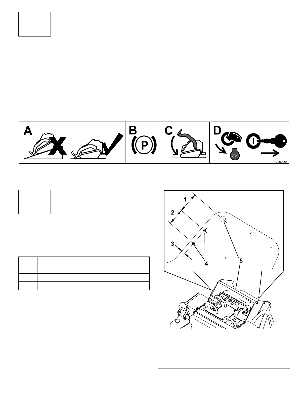
PreparingtheMachine
NoPartsRequired
Procedure
1.Parkthemachineonalevelsurface.
2.Engagetheparkingbrake.
3.Lowertheloaderarms.
4.Shutofftheengineandremovethekey.
g036689
Figure1
2
InstallingtheShield
Brackets
Partsneededforthisprocedure:
1Rightshieldbracket
1
Leftshieldbracket
4
Bolt(1/4x3/4inch)
4
Locknut(1/4inch)
Procedure
1.Measureinfromtheedgesoftheframeas
illustratedinFigure2andmarkthelocations
oftheholesformountingtheshieldbracketon
bothsidesofthemachine.
Note:Iftheholesexist,skiptostep3.
Figure2
1.7.0cm(2-3/4inches)
2.5.7cm(2-1/4inches)5.Referencebar
3.1.3cm(1/2inch)
4.Holes
g213269
2
Page 3

2.Drillahole(9/32inch)throughtheframeateach
markedlocation.
3.Installtheleftshieldbracketontheleftframe
using2bolts(1/4x3/4inch)and2locknuts(1/4
inch)asshowninFigure3.
Figure3
1.Bolts(1/4x3/4inch)3.Locknut(1/4inch)
2.Leftshieldbracket
4.Installtherightshieldbracketontherightframe
using2bolts(1/4x3/4inch)and2locknuts(1/4
inch),similartoFigure3.
3
AssemblingtheOperator
Shield
Partsneededforthisprocedure:
2
Shieldsupport
1
Shield
8
Bolt(1/4x1-1/2inch)
8Washer
8
Locknut(1/4inch)
g202825
Procedure
1.Assembletheshieldandexibleskirttothe
shieldsupports,asillustratedinFigure4,using
8bolts(1/4x1-1/2inch),8washers,and8
locknuts(1/4inch).
Figure4
1.Locknut(8)5.Skirt
2.Washer(8)6.Shieldsupport(2)
3.Shield7.Shieldbracket(2)
4.Bolt(8)
2.Slidetheshieldsupportsintothepocketsinthe
shieldbracketsonthetractionunit(Figure4).
Note:Theskirtshoulddrapeovertheengine
orhood.
3
g202842
Page 4

4
ReplacingtheQuick-Attach
Assembly
Partsneededforthisprocedure:
1
Quick-attachassembly
Procedure
1.Laythestumpgrinderatontheoor.
2.Placewoodblocksunderthebodyofthestump
grindersothatthequick-attachplateisoffthe
oor.
3.Removethelargebolt(1x2-1/4inch),washer,
nut(1inch),2smallbolts(1/2x1-1/2inches),
and2nuts(1/2inch)securingthequick-attach
assemblytothestumpgrinder(Figure5).
Removetheassembly .
5.Torquethelargebolt(1x2-1/4inch)to406N∙m
(300ft-lb),andtorquethesmallbolts(1/2x
1-1/2inches)to101N∙m(75ft-lb).
6.Routethehosesthroughthehoseloop(Figure
6).
g208071
Figure6
1.Hoseloop2.Hoses
Figure5
1.Largebolt(1x2-1/4inch),
washer,andnut(1inch)
2.Smallbolt(1/2x1-1/2
inches)andnut(1/2inch)
4.Installthenewquick-attachassemblytothe
stumpgrinderusingthehardwareyouremoved,
asshowninFigure5.
3.Quick-attachassembly
Note:Thenewquick-attachassemblyhasa
widerhoseloop.
g206389
4
 Loading...