

Page 1
1
PreparingtheMachine
FormNo.3413-121RevA
DoubleDetentValveKit
TX1000CompactToolCarrier
ModelNo.23171
InstallationInstructions
WARNING
CALIFORNIA
Proposition65Warning
ThisproductcontainsachemicalorchemicalsknowntotheStateofCaliforniato
causecancer,birthdefects,orreproductiveharm.
NoPartsRequired
Procedure
Important:Caporpluganydisconnectedhydraulichoses,tubes,orcomponentportstopreventcontaminating
thesystem.
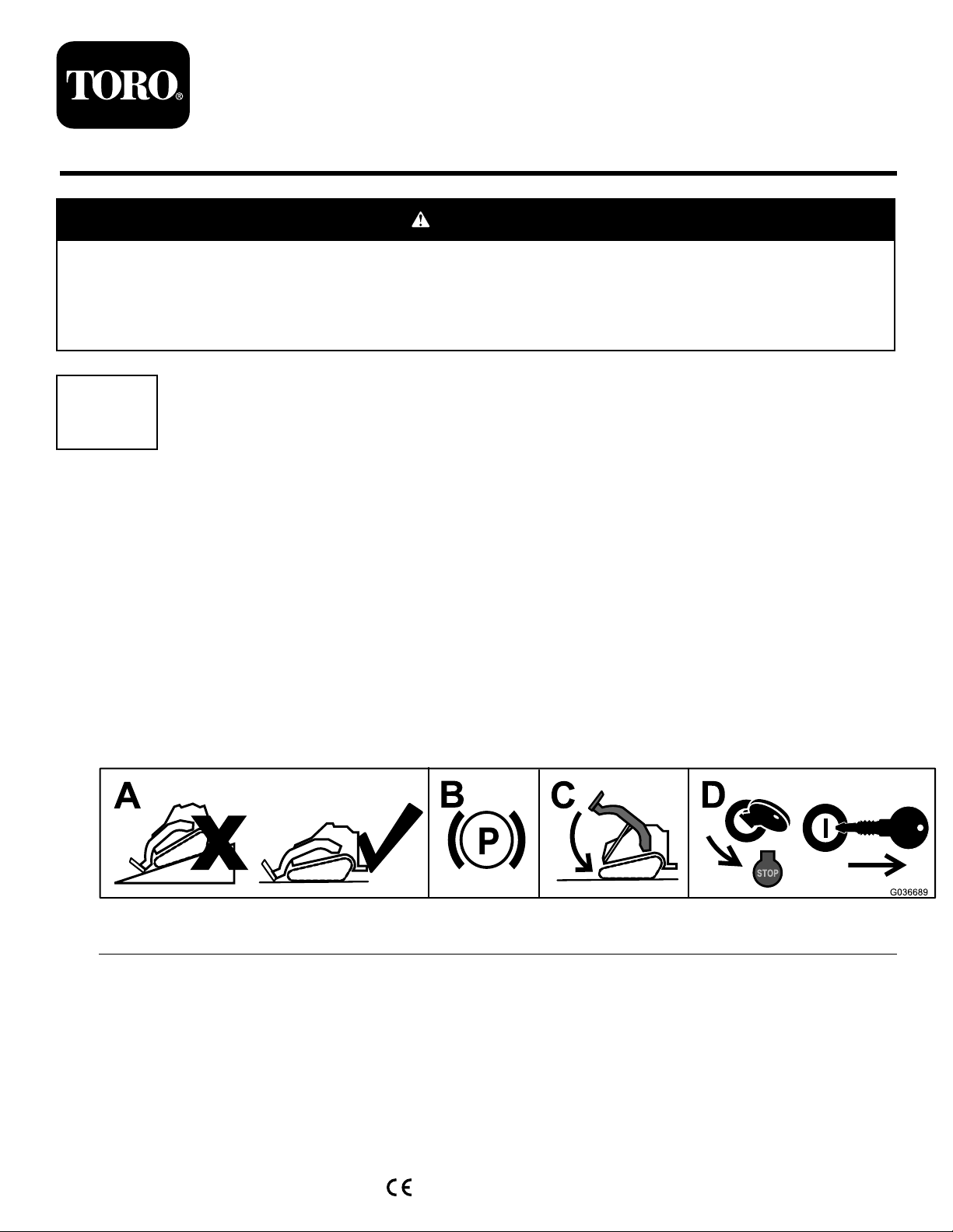
1.Parkthemachineonalevelsurface.
2.Engagetheparkingbrake.
3.Lowertheloaderarms.
4.Shutofftheengineandremovethekey.
Figure1
g036689
©2017—TheT oro®Company
8111LyndaleAvenueSouth
Bloomington,MN55420
Registeratwww.T oro.com.
OriginalInstructions(EN)
PrintedintheUSA
AllRightsReserved
*3413-121*A
Page 2
2
AccessingtheAuxiliary Valve
NoPartsRequired
Procedure
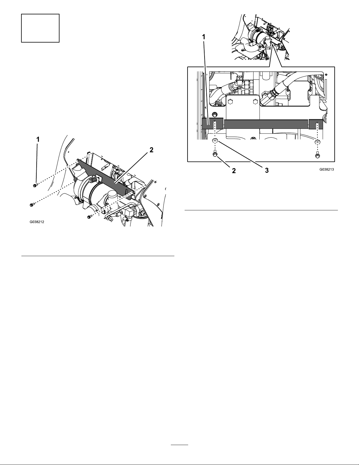
1.Openthehoodandsecuretheproprod.
2.Removethecoverplate(Figure2).
g038213
Figure3
1.Rubberbafe3.Washer(1/4inch)
2.Bolt(1/4x3/4inch)
Figure2
1.Bolt(1/4x3/4inch)2.Coverplate
3.Removethe2boltsand2washerssecuringtherubber
bafeandlowerthebafe(Figure3).
4.Liftthecushionpad.
g038212
2
Page 3
3
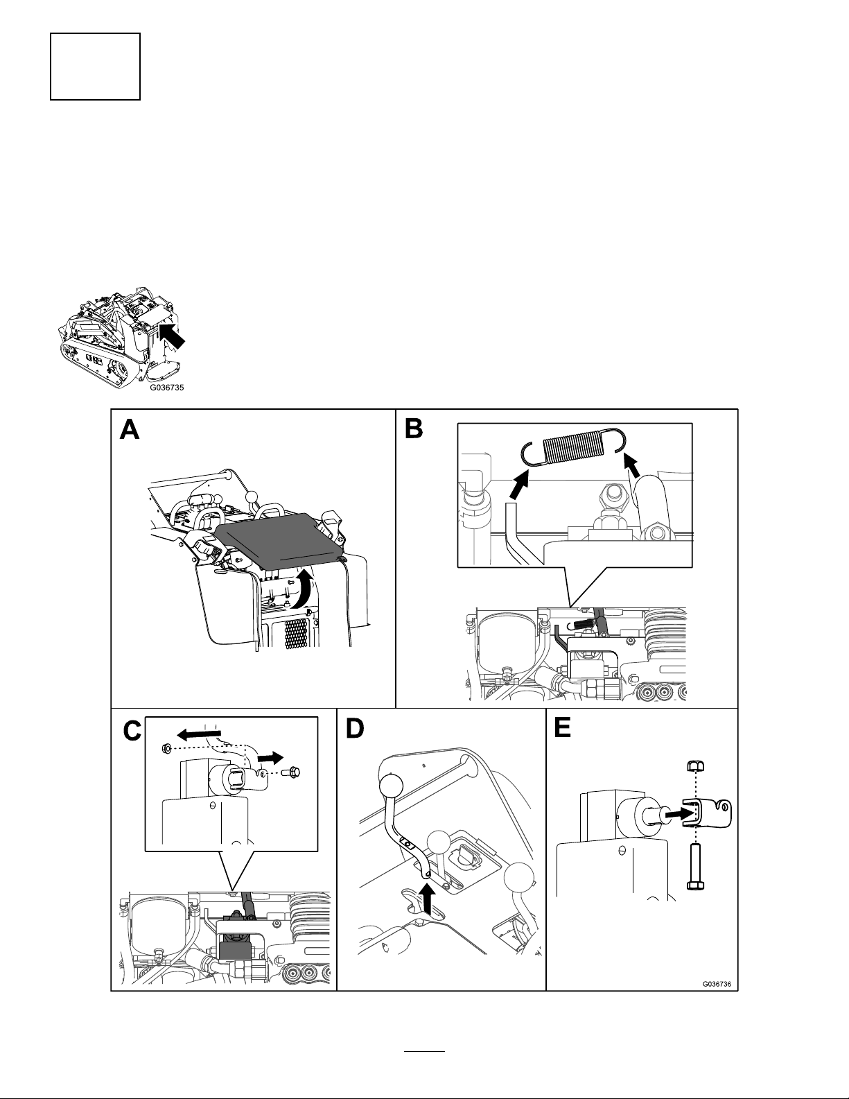
RemovingtheAuxiliary Handle
NoPartsRequired
Procedure
RemovetheauxiliaryhandleasshowninFigure4.Retainallpartsforlaterinstallation.
Figure4
3
g207301
Page 4
4
RemovingtheExisting RadiatorHose,Outlet,and Gasket
NoPartsRequired
Procedure
1.Removetheradiatorscreenatthebackofthemachine
andlocatethedrainplugatthebottomrightcorner.
2.Placealargedrainpanbeneaththedrainplugorice
andunthreadtheplug(Figure5).
Figure5
g207297
Figure6
1.Radiatorhose3.Radiator
2.Upperoutlet4.Loweroutletandgasket
6.Removetheradiatorhosefromthemachine(Figure6).
Note:Youmaydiscardtheremovedhose.
7.Removethe2mountingboltsfromtheoutletontop
oftheengine(Figure6).
8.Removetheexistingstraight-endoutletandgasket
fromtheengine.
Note:Youmaydiscardtheremovedstraight-end
outlet,gasket,andassociatedhardware.
g208168
1.Radiator(withscreen
removed)
3.Loosentheupperhoseclampandremovethehose
fromtheoutletontheradiator(Figure6).
4.Temporarilyplugtheoutletontheradiatoranddrain
thedetachedhose.
5.Loosenthelowerhoseclampandremovethehose
fromtheoutletontheengine.
Note:Retainthehoseclampsforinstallationin5
InstallingtheNewRadiatorHose,OutletandGasket
(page5).
2.Drainplug
4
Page 5

5
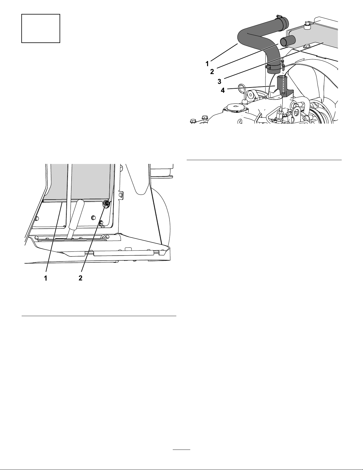
InstallingtheNewRadiator Hose,OutletandGasket
Partsneededforthisprocedure:
1
Outlet
1
Gasket
2M8Bolt
1Radiatorhose
Procedure
1.Installtheradiatordrainplug(Figure7).
Figure8
1.Newradiatorhose3.Upperoutlet
2.Newangledoutletand
gasket
7.Removetheradiatorcapandllthetanktothe
neckwitha50/50solutionofwaterandpermanent
ethylene-glycolantifreeze.RefertoyourOperator’s
Manual.
4.M8bolts
g207296
Figure7
1.Radiator(withscreen
removed)
Note:Ensurethatdrainplugdoesnotleak;youmay
needtoapplythreadsealanttothedrainplug.
2.Installtheradiatorscreen.
3.Alignthegasketandoutletwiththemountingholesand
portontopoftheengine,withtheangledendofthe
outletfacingtherightsideofthemachine(Figure8).
4.Threadtheboltsintothemountingholesandtighten
theboltsto18to20N-m(13to15ft-lb).
5.Usingthepreviouslyremovedhoseclamps,installthe
lowerendoftheradiatorhosetotheangled-endoutlet
andtightenthehoseclamp(Figure17).
6.Installtheupperendoftheradiatorhosetothe
straight-endoutletontheradiatorandtightenthehose
clamp(Figure8).
2.Radiatorpluginstalled
8.Checkthelevelofcoolantintheexpansiontankand
addcoolantuntilitreachesthesidemark.Referto
yourOperator’sManual.
g208168
5
Page 6

6
RemovingtheExisting AuxiliaryValve
NoPartsRequired
Procedure
1.Removethe2hosesattachedtothetee-ttinginthe
frontoftheauxiliaryvalve(Figure9).
Note:Youmayalsoneedtoremovetheclampplate
ontheleftsideofthemachinetoremovetheauxiliary
hosesfromthevalve.Retainitforlaterinstallation.
5.Disconnectthereturnhoseattachedtotheelbow
ttingatthebackoftheauxiliaryvalvebyloosening
thehoseclamp(Figure10).
6.Temporarilyplugthereturnhose.
7.Removetheelbowttingfromthebackoftheauxiliary
valve(Figure10).
1.Longhose
2.Tee-tting
3.Shorthose
Figure9
4.Auxiliaryvalve(front)
5.Hoseclamp
6.Returnhose
g207299
Figure10
1.Returnhose3.Auxiliaryvalve
2.Elbowtting
8.Disconnecttheballswitchplugfromthewireharness
socket.
9.Removethe3boltsandnutssecuringtheauxiliary
valvetothebracket(Figure11).
g206974
4.Markedpressurehoses
2.Temporarilyplugthedetachedhoses.
3.Markthe3pressurehosesandportsshowninFigure
10withtheircorrespondingportlocationssothatyou
caninstallthemintothecorrectportslater.
4.Disconnectthe3pressurehosesfromthestraight
ttingsonthesideoftheauxiliaryvalve(Figure10).
g207304
Figure11
Lowerauxiliaryttingnotshownforclarity
10.Removetheauxiliaryvalve.
6
Page 7

7
ReplacingtheFittings
NoPartsRequired
Procedure
Note:Retainallpartsremovedfromoldvalveforinstallation
ontonewvalve.
1.Removethe3straightttingsfromthesideofthe
valve(Figure12).
2.Removetheteettingfromthebackofthevalve
(Figure12).
3.Removetheballswitchfromthesideoftheauxiliary
valve(Figure12).
g207294
Figure13
7.Whilemaintainingproperorientation,torquethetee
ttingto78.6to97.6N-m(58to72ft-lb).
8.Removetheplugfromthesideofthenewauxiliary
valveandthreadtheballswitchintotheport(Figure
13).
Figure12
4.Installthe3straightttingstothe3sideports(Figure
13).
5.Tightenthestraightttingsto78.6to97.6N-m(58
to72ft-lb).
6.Handtightentheteetting,thenorienttheendsata
45-degreeangleasshowninFigure13.
9.Tightentheballswitchto24.4to29.8N-m(18to22
ft-lb).
g207298
7
Page 8

8
InstallingtheNewAuxiliary Valve
Partsneededforthisprocedure:
1Auxiliaryvalve
Procedure
1.Aligntheauxiliaryvalvewiththe3holesonthe
mountingbracket.
2.Securetheauxiliaryvalvetothebracketwiththefront
3boltsandnuts(Figure14).
Figure14
Lowerauxiliaryttingnotshownforclarity
Important:Ensurethattheboltsareorientedas
showninFigure14.
3.Connectthelongandshorthosesintotheteetting
onthefrontoftheauxiliaryvalve(Figure15).
g206974
Figure15
1.Longhose4.Newauxiliaryvalve
2.Teetting
3.Shorthose
Note:Ensurethatthelonghose(fromthegearpump)
isroutedthroughtherubberbafebeforeinstalling
g207305
ittotheteetting.
4.Tightenthehosesontheteettingto50.2to63.7
N-m(37to47ft-lb).
5.Attachtheelbowttingtotheportonthebackofthe
auxiliaryvalve(Figure16).
5.Hoseclamp
6.Returnhose
8
Page 9

Figure16
1.Returnhose3.Auxiliaryvalve
2.Elbowtting
4.Markedpressurehoses
6.Tightentheelbowttingto78.6to97.6N-m(58to
72ft-lb).
7.Removetheplugfromthereturnhose,andattachitto
theelbowttingwiththehoseclamp(Figure16).
8.Attachthe3pressurehosestothestraightttingson
thesideoftheauxiliaryvalveaccordingtothemarks
madein3of6RemovingtheExistingAuxiliaryValve
(page6).
Note:Ifyouremovedtheclampplatein4of6
RemovingtheExistingAuxiliaryValve(page6),install
itnow .
9.Tightenthe3pressurehosesto50.2to63.7N-m(37
to47ft-lb).
10.Attachtheballswitchplugintothewireharness
connector.
g207295
11.Attachtheextensionplugintothesocketforthe
foot-switch.
12.Plugtheextensionwireintothemainwireharnessfor
thefootswitch.
9
Page 10

9
InstallingtheAuxiliary Handle
NoPartsRequired
Procedure
Installtheauxiliaryhandleusingthepartsyouremovedin3RemovingtheAuxiliaryHandle(page3).
Figure17
g207300
10
Page 11

10
CompletingtheInstallation
NoPartsRequired
Procedure
1.Checkandtightenallttingsandhydraulicconnections.
2.Checkthecoolantandhydraulicuidlevelsand
replenishitasrequired;refertotheOperator’ sManual
foryourmachine.
3.Startthemachineandallowthehydraulicsystemto
pressurize.
4.Stoptheengineandcheckthehydraulictubes,hoses,
andttingsforleaks.
Note:Repairallleaksbeforeoperatingthemachine.
5.Installthe3boltstosecuretheheatcover(Figure17).
Figure18
1.Bolt2.Heatcover
6.Installthe2boltsand2washerstosecuretherubber
bafetothemachine(Figure19).
g038213
Figure19
1.Rubberbafe3.Washer(1/4inch)
2.Bolt(1/4x3/4inch)
7.Liftuponthetabsecuringtheprop-rodandlowerthe
hood.
8.Tightenthehood-lockingscrewtosecurethelatch.
9.Lowertheoperator’spad.
10.Testtheauxiliaryvalvefunctioninboththeforward
andrearwarddirections.
g038212
11
Page 12

 Loading...