

Page 1
Form No. 3352-367 Rev A
Adjustable Forks
For C ompact Utility Loaders
Model No. 23164—Serial No. 260000001 and Up
G001351
Register your product at www.Toro.com Original Instructions (EN)
Page 2
Contents
Introduction ......................................................... 2
Safety .................................................................. 3
Safety and Instructional Decals ........................ 3
Setup ................................................................... 4
1 Assembling the Forks ................................... 4
Product Overview ................................................. 5
Specifications ................................................ 5
Operation ............................................................ 6
Installing the Forks on the Traction
Unit ............................................... 6
Removing the Attachment ............................... 6
Operating Tips............................................... 7
Maintenance ......................................................... 8
Storage.......................................................... 8
Introduction
Read this information carefully to learn how to operate
and maintain your product properly and to avoid injury
and product damage. You are responsible for operating
the p roduct properly and s afely.
serious injury or death if you do not follow the
recommended precautions.
Figure 2
1. Safety alert symbol.
This manual uses two other words to highlight
information. Important calls attention to special
mechanical information and Note emphasizes general
information worthy of special attention.
You may contact Toro directly at www.Toro.com for
product and accessor y information, help finding a
dealer, or to register your product.
Whenever you need service, genuine Toro parts, or
additional information, contact an Authorized Service
Dealer or Toro Customer Service and have the model
and serial numbers of your product ready. Figure 1
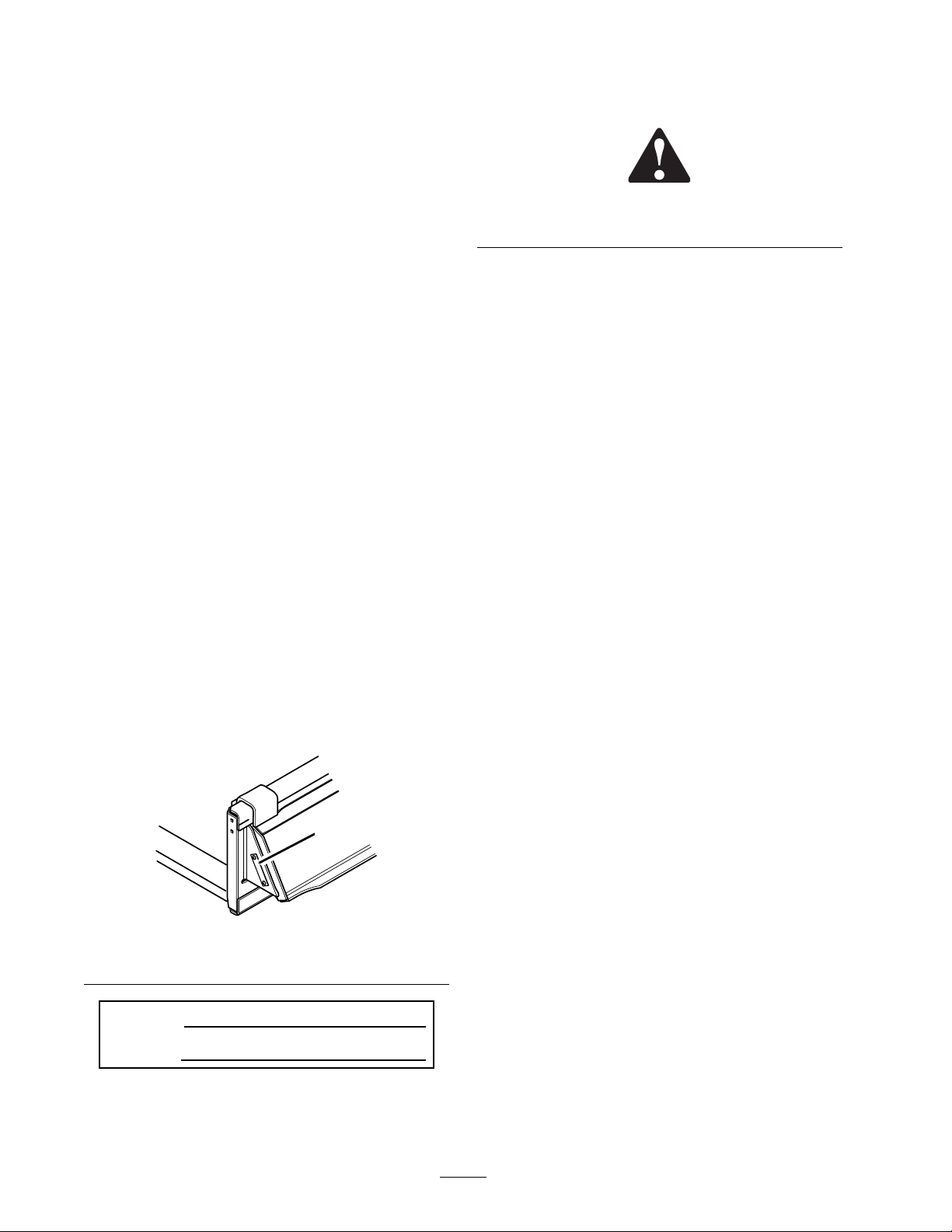
identifies the location of the model and serial numbers
on the product. Write the numbers in the space
provided.
G001352
1
Figure 1
1. Location of Model and Serial Number
Model No.
Serial N o.
This manual identifies potential hazards and has
safety messages identified by the safety alert symbol
(Figure 2), which signals a hazard that may cause
© 2005—The Toro® Company
8111 Lyndale Avenue South
Bloomington, MN 55420
Contactusatwww.Toro.com.
2
Printed in the USA.
All Rights Reserved
Page 3
Safety
When the engine is off, attachments in
the raised position can gradually lower.
Someonenearbymaybepinnedorinjured
by the attachment as it lowers.
Always lower the attachment lift each time
youshutoffthetractionunit.
When going up or down hill, the machine
could overturn if the heavy end is toward
the downhill side. Someone may be pinned
or seriously injured by the machine if it
overturns.
Operate up and down slopes with the heavy
end of the machine uphill. Empty for ks will
make the rear end heavy and loaded forks
will make the front end heavy.
Ifyoustepoffo
load raised, t
Someone nearb
ftheplatformwiththe
he machine could tip forward.
y may be pinned or injured.
Lower the forks before stepping off of the
platform.
Iftheforksarenotkeptlevelwhilelifting,
the load could be inadvertently dumped on
the operator. The operator could be injured
when the load is dumped.
When lifting the forks, tilt them forward
to keep them level and prevent spilling
backwards.
Safety and Instructional Decals
Safety decals and instructions are easily visible to the operator and are located near any
area of potential danger. Replace any decal that is damaged or lost.
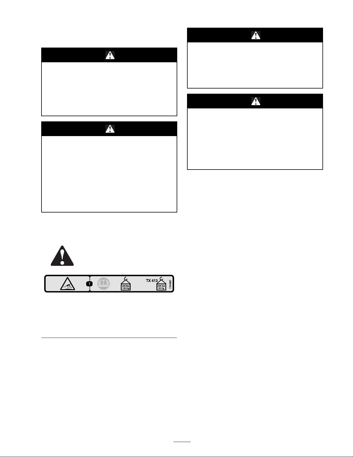
110-0067
1. Tipping hazard, exceeding rated load capacity can cause
instability—read the Operator’s Manual; do not exceed
maximum load capacity of 300 lbs (136kg); for TX 413
models, do not exceed maximum load capacity of 205 lbs
(93kg).
3
Page 4
Setup
Loose Parts
Use the chart below to verify that all parts have been shipped.
Step
1
Adjustable forks frame
Fork
Upper fork frame
Bolt, 3 /8 x 1 inch
Locknut, 3/8 inch
Description
Step
1
Assembling
Parts needed for this step:
1
Adjustable forks frame
2
Fork
1
Upper fork frame
7
Bolt, 3/8 x 1 inch
7
Locknut, 3/8 inch
the Forks
Qty.
1
2
1
7
7
Assemble the forks
4
Use
3
5
4
5
4
1
2
Procedure
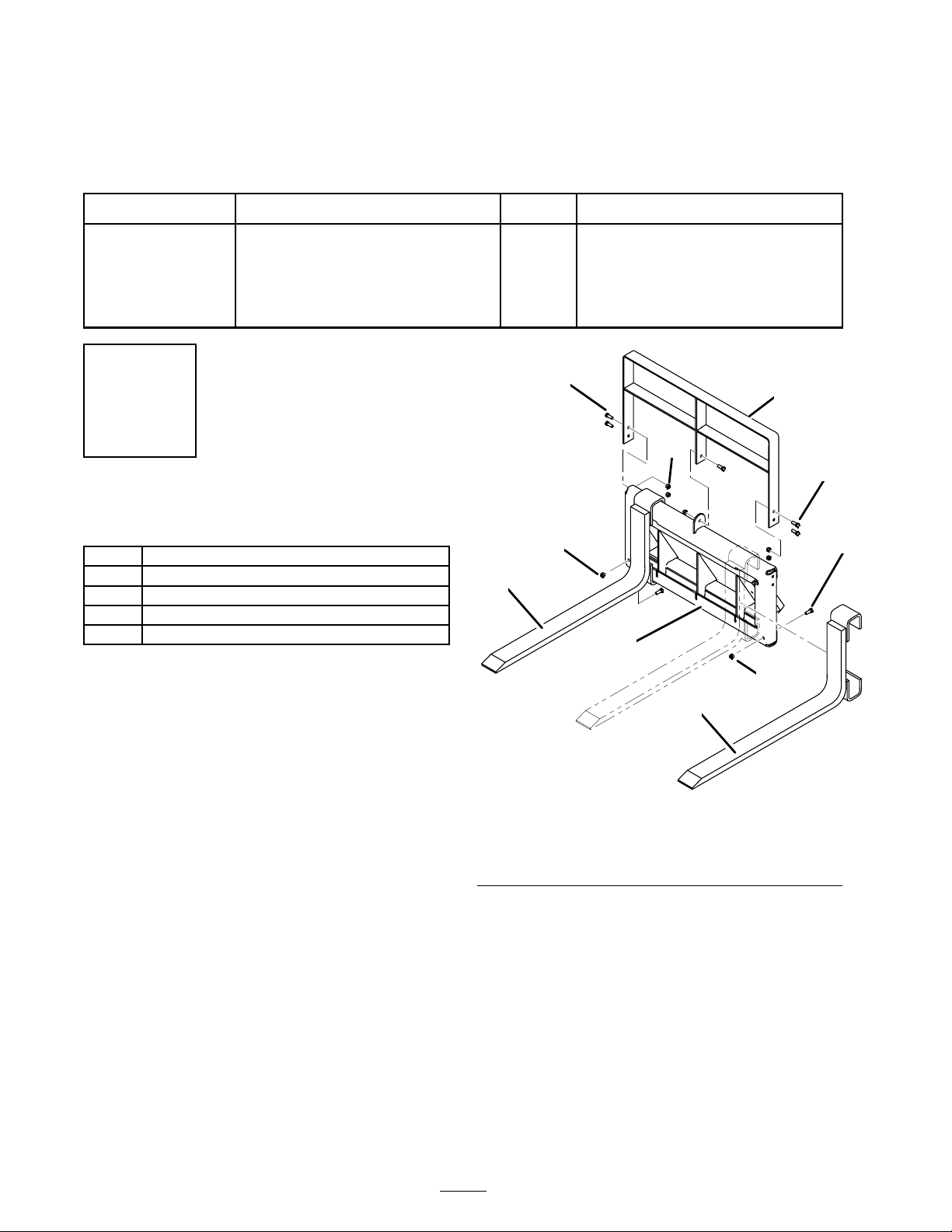
1. Install the forks over the adjustable fork frame
asshowninFigure3. Secureeachforkwitha
bolt (3/8 x 1 inch) and locknut (3/8 inch).
5
1
G001353
Figure 3
1. Fork 4. Bolt, 3/8 x 1 inch
2. Fork frame 5. Locknut, 3/8 in ch
3. Upper fo
rk frame
2. Install the upper fork frame over the assembly
as shown in Figure 3. Secure the upper frame
using 5 bolts (3/8 x 1 inch) and 5 locknuts
(3/8 inch).
3. Tighten all fasteners securely.
4
Page 5
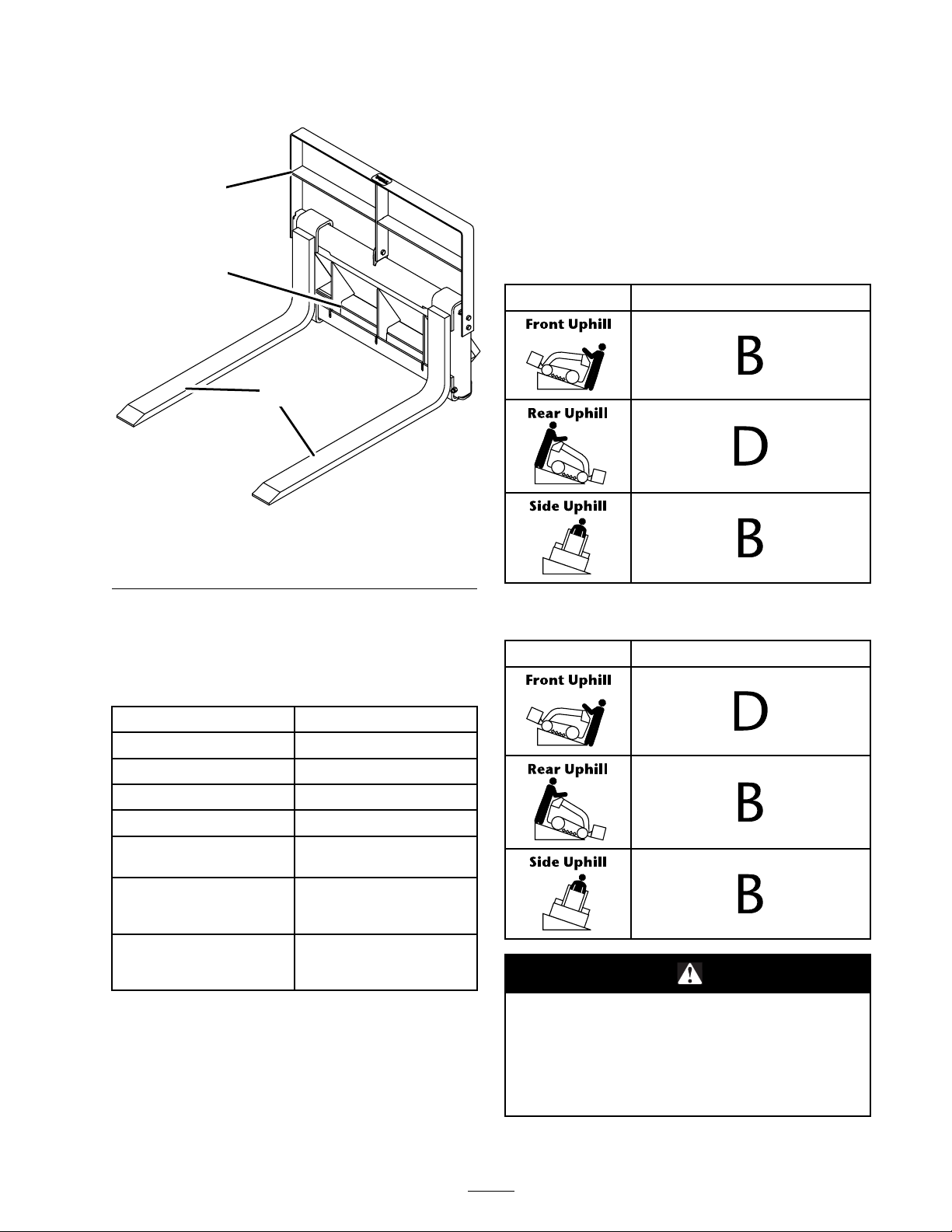
Product Overview
3
slope for the same rating and hill position in the
Stability Data section of the traction unit Operator’s
Manual.
Important: Theforksareratedforuse
with the counterweight. Do not use the forks
without the counterweight or the traction unit
will become unstable.
2
1
G001354
Figure 4
1. Fork 3. Upper frame
2. Adjustable fork frame
Specificat
ions
Note: Specifications and design are subject to
change without notice.
Stability With a Loaded Forks
Orientation Stability Ra
ting
Stability With Unloaded Forks
Orientation Stability Rating
Overall width
Overall length
Overall height
Weight
Fork length
Fork cross-section size
Fork width adjustment
range (outside to outside
dimensions)
Load rating capacity (per
SAE J1197)
31.3 inch
41.2 inches (105 cm)
27.0 inches (69 cm)
162 lbs (7
31.5 inches (80 cm)
3.0 inches (7.6 cm) x 1.0
inch (2.5 cm)
6.5 to 30
76 cm)
300 lbs (152 Kg)
205 lbs (93 Kg) for TX413
models
es (80 cm)
4Kg)
.0 inches (17 to
Stability Ratings
To determine the degree of slope you can traverse
with the forks installed on a traction unit, find the
stability rating for the hill position you want to
travel in the table below, then findthedegreeof
Exceeding the maximum slope can cause
the traction unit to tip. If the traction unit
tips, you or bystanders could be crushed.
Do not drive the traction unit on a slope
steeper that the maximum slope.
5
Page 6
Operation
Installing the Forks on the
Traction Unit
Important: Before installing the
attachment, ensure that the mount plates
are free of any dirt or debris and that the
pins rotate freely. If the p ins do not rotate
freely, g rease them; refer to the traction unit
Operator’s Manual for more information.
Important: If the pins do not rotate to
the engaged position, the mount plate
is not fully aligned with the holes in the
attachment receiver plate. Check the
receiver plate and clean it if necessar y.
If you do not fully seat the quick attach
pins through the attachment mount
plate, the attachment could fall off of the
traction unit, crushing you or bystanders.
1. Position the attachment on a level surface with
enough space behind it to accommodate the
traction unit.
2. Start the engine.
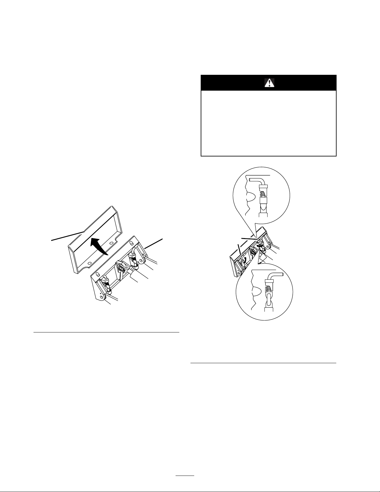
3. Tilt the attachment mount plate forward.
4. Position mount plate into the upper lip of the
attachment receiver plate (Figure 5).
1
2
G001382
Figure 5
1. Mount plate 2. Receiver plate
5. Raise the loader arms while tilting back the
mount plate at the same time.
Ensure that your quick attach pins are
fully seated in the attachment mount
plate.
3
1
2
G001383
Figure 6
1. Quick attach pins (show n
in the engaged position)
2. Disengaged position
3. Engaged position
Important: The attachment should be
raised enough to clear the ground, and the
mount plate should be tilted all the way
back.
6. Stop the engine.
7. Engage the quick attach pins, ensuring that
they are fully seated in the mount plate
(Figure 6).
Removing the Attachment
1. Lower the attachment to the ground.
2. Stop the engine.
3. Disengage the quick attach pins by turning
them to the outside.
4. Start the engine, tilt the mount plate forward,
and back the traction unit away from the
attachment.
6
Page 7

Operating Tips
• To adjust the forks, slide them along the frame
to the desired width. The forks should always
be adjusted to the widest possible setting to
ensure that the load will be as stable as possible.
• When transporting a load, keep the forks as
close to the ground as possible.
• Neverusetheforksforpryingasdamagemay
occur.
• Never attempt to lift more than the rated lift
capacity of the traction unit.
7
Page 8

Maintenance
Do Not
someone could star t the engine. Accidental
starting of the engine could seriously injure
you or other bystanders.
Remove the key from the ignition switch
before performing any maintenance.
leave the key in the ignition switch,
Storage
1. Before long
with mild de
and grime f
2. Paint all s
is availab
Dealer.
3. Store the a
storage a
it clean.
term storage, wash the attachment
tergent and water to remove dirt
rom the entire attachment.
cratched or bare metal surfaces. Paint
le from your Authorized Service
ttachment in a clean, dry ga rage or
rea. Cover it to protect it and keep
8
 Loading...