

Page 1
Form No. 3358-367 Rev A
Backhoe Mounting Kit
For TX Compact Utility Loaders
Model No. 23162
Installation Instructions
Important: T his document contains the inf or mation f or installing and connecting the
backhoe to a TX series compact utility loader . R efer to the Backhoe Operator’ s Man ual f or
safety , operation, and maintenance inf or mation.
Loose Parts
Use the chart below to verify that all parts have been shipped.
Step
Lanyard/Hydraulics Lever Clamp
Screw
1
2
3
4
Washer
Locknut
Holding pin
Pin
Link
Lynch pin
Hydraulics lever clamp
Description
Step
1
Installing the Lanyard to the
Seat
Qty.
1
1
1
1
1
1
2
4
1
Install the lanyard to the seat.
Change the tilt cylinder pin.
Connect the backhoe to the traction
unit.
Prepare the backhoe for operation.
Use
Parts needed for this step:
1
Lanyard/Hydraulics Lever Clamp
1
Screw
1
Washer
1
Locknut
1
Holding pin
Procedure
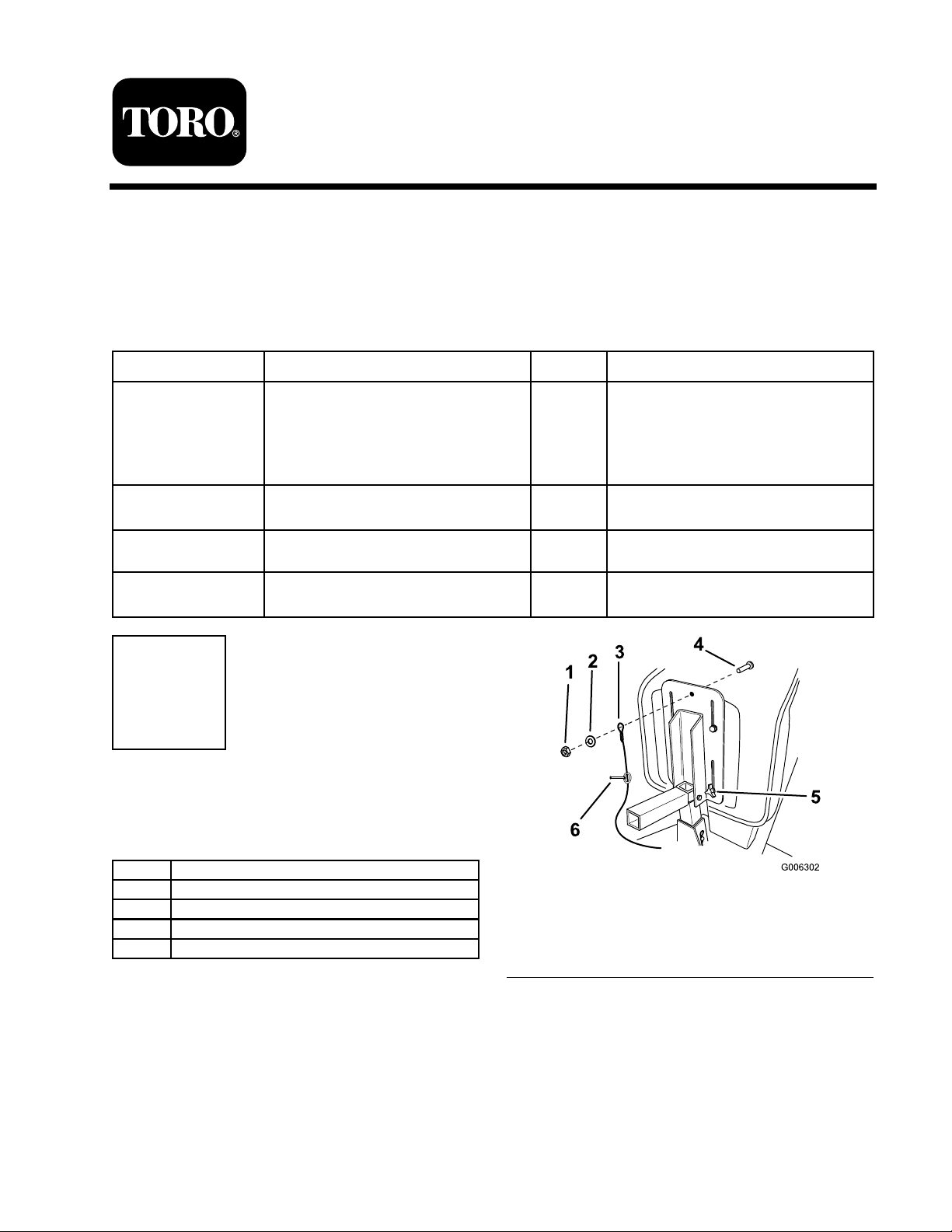
1. Tilt the seat forw ard, loosen the seat knobs
and slide the seat forw ard.
2. Install the holding pin onto the lanyard.
3. Install the lanyard, attac hed to the h y draulics
lev er clamp , to the seat base with a screw ,
w asher , and loc kn ut ( Figure 1 ).
© 2007—The Toro® Company
8111 Lyndale Avenue South
Bloomington, MN 55420
Figure 1
1. Locknut
2. Washer 5. Seat knobs
3. Lanyard attached to the
hydraulics lever clamp
Register at www.Toro.com. Original Instructions (EN)
4. Screw
6. Holding pin
Printed in the USA.
All Rights Reserved
Page 2
Step
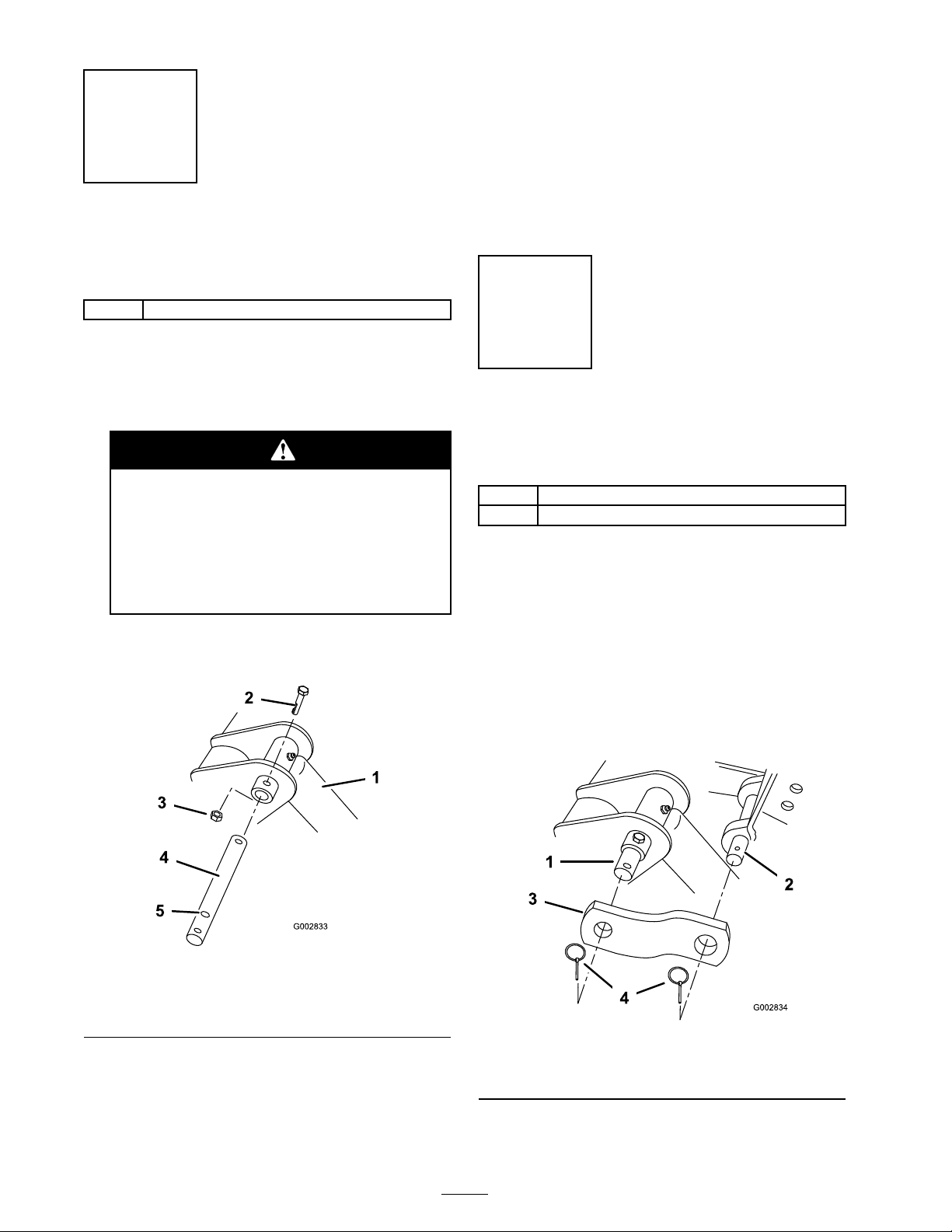
4. Install the new pin into position and secure
it with the bolt and n ut remo v ed previously ,
using the middle hole on the pin ( Figure 2 ).
2
Changing the Tilt Cylinder
Pin
Parts needed for this step:
1
Pin
Procedure
1. Bloc k up the mount plate so that it cannot
swing forw ard.
W hen y ou r emo v e the tilt cylinder pin,
the mount plate may s wing f orw ard. Y our
feet or hands, or those of bystander s,
could be cr ushed.
Block up the mount plate bef or e
r emo ving the tilt cylinder pin.
2. R emo v e the bolt and n ut securing the upper
tilt cylinder pin on the traction unit ( Figure 2 ).
5. Grease the pin using the fitting on the tilt
cylinder .
Note: Lea v e the new pin installed, ev en when
the bac khoe is remo v ed.
Step
3
Linking the Backhoe to the
Traction Unit
Parts needed for this step:
2
Link
4
Lynch pin
Procedure
1. Connect the bac khoe mount plate and
h y draulic hoses to the traction unit as described
in the traction unit Operator’ s Manual .
2. Star t the engine .
Figure 2
1. Tilt cylinder 4. New tilt cylinder pin
2. Bolt 5. Middle hole
3. Nut
3. Using a hammer and punc h, remo v e the tilt
cylinder pin.
3. Tilt the bac khoe bac k until the bac khoe link
pin is appro ximately 6 inc hes (15 cm) from the
tilt cylinder pin ( Figure 3 ).
Figure 3
1. Tilt cylinder pin 3. Link
2. Backhoe link pin 4. Lynch pin
2
Page 3

Y ou could pinch and/or cr ush y our hand
when tilting the backhoe.
K eep a w ay fr om the mo ving backhoe
when tilting .
4. Slide a link on one end of the tilt cylinder pin
and the bac khoe link pin and secure it with tw o
lync h pins ( Figure 3 ).
Note: Y ou ma y need to mo v e the attac hment
tilt lev er to line up the holes in the links with
the pins .
5. R e peat ste p 4 for the other side .
Step
Figure 5
1. Hydraulics lever clamp 4. Loader arm/attachment tilt
lever
2. Auxiliary hydraulics lever 5. Parking brake
3. Reference bar
4. Pull the lev er and clamp do wn to the reference
bar so that the clamp routes behind the loader
ar m/attac hment tilt lev er .
4
Preparing the Backhoe for
Operation
Parts needed for this step:
1
Hydraulics lever clamp
Procedure
1. Dri v e to the w ork location.
2. Set the throttle 2/3 of the w a y to the fast
(rabbit) position on the traction unit.
3. Slide the end of the h y draulics lev er clamp
o v er the auxiliar y h y draulics lev er ( Figure 4 or
Figure 5 ).
5. Set the parking brak e , to the on position, into
the slot so that the clamp catc hes under the
brak e lev er ( Figure 6 or Figure 7 ).
Figure 4
1. Hydraulics lever clamp 4. Loader arm/attachment tilt
lever
2. Auxiliary hydraulics lever 5. Parking brake
3. Reference bar
Figure 6
1. Auxiliary hydraulics lever 3. Parking brake
2. Hydraulics lever clamp
3
Page 4

2. R emo v e the lync h pins securing the links and
remo v e the links ( Figure 3 ).
Note: Y ou ma y need to adjust the tilt lev er
slightly to loosen the links .
3. Secure the links and tw o lync h pins for storag e
on the pins on the bac khoe and the other tw o
lync h pins on the traction unit tilt cylinder pin.
4. Contin ue disconnecting the bac khoe as
described in the bac khoe and traction unit
Operator’ s Manuals .
Storage
Figure 7
1. Auxiliary hydraulics lever 3. Parking brake
2. Hydraulics lever clamp
If the traction unit mo v es while an
operator is seated on the backhoe, the
traction unit and backhoe could tip o v er .
Someone may be pinned or seriousl y
injur ed by the machine if it o v er tur ns.
Set the par king brak e bef or e an y one gets
on the backhoe and do not attempt to
mo v e the traction unit while sitting on
the backhoe.
6. Use the bac khoe as directed in the Bac khoe
Operator’ s Manual .
Step
Storing the Hydraulics Lever
Clamp
1. R emo v e the h y draulics lev er clamp from the
controls .
2. Secure the clamp on the control console side
with the holding pin attac hed to the lanyard
( Figure 8 ).
5
Disconnecting the Backhoe
from the Traction Unit
No Parts Required
Procedure
W hen finished using the bac khoe , disconnect and
store the links as described belo w:
1. Star t the engine .
Figure 8
1. Controls console 4. Holding pin
2. Hole in the side of the
console
3. Hydraulics lever clamp
4
5. Lanyard
 Loading...