

Toro 23160 Operator's Manual
Backhoe
for Dingo Compact Utility Loaders
Model No. 23160—220000001 & Up
Form No. 3350-453
Operator ’s Manual
Original Instructions (EN/GB)
Contents
Page
Introduction 2. . . . . . . . . . . . . . . . . . . . . . . . . . . . . . . . .
Safety 2. . . . . . . . . . . . . . . . . . . . . . . . . . . . . . . . . . . . . .
Safety and Instruction Decals 3. . . . . . . . . . . . . . . . .
Specifications 5. . . . . . . . . . . . . . . . . . . . . . . . . . . . . . . .
Stability Ratings 5. . . . . . . . . . . . . . . . . . . . . . . . . . .
Setup 6. . . . . . . . . . . . . . . . . . . . . . . . . . . . . . . . . . . . . .
Loose Parts 6. . . . . . . . . . . . . . . . . . . . . . . . . . . . . . .
Installing the Dingo 200/300 Series Backhoe Kit 6.
Installing the Dingo TX Backhoe Kit 8. . . . . . . . . .
Greasing the Backhoe 8. . . . . . . . . . . . . . . . . . . . . .
Installing a Bucket 8. . . . . . . . . . . . . . . . . . . . . . . . .
Adjusting the Seat 9. . . . . . . . . . . . . . . . . . . . . . . . .
Operation 9. . . . . . . . . . . . . . . . . . . . . . . . . . . . . . . . . . .
Operation Checklist 9. . . . . . . . . . . . . . . . . . . . . . . .
Backhoe Overview 10. . . . . . . . . . . . . . . . . . . . . . . . .
Controls 10. . . . . . . . . . . . . . . . . . . . . . . . . . . . . . . . .
Connecting the Backhoe to the Traction Unit 10. . . .
Operating the Backhoe 11. . . . . . . . . . . . . . . . . . . . . .
Securing the Backhoe for Transport 13. . . . . . . . . . .
Disconnecting the Backhoe from the Traction Unit 14
Maintenance 15. . . . . . . . . . . . . . . . . . . . . . . . . . . . . . . . .
Service Interval Chart 15. . . . . . . . . . . . . . . . . . . . . .
Greasing and Lubrication 15. . . . . . . . . . . . . . . . . . . .
Changing the Bucket Orientation 16. . . . . . . . . . . . . .
Adjusting the Boom Speed 16. . . . . . . . . . . . . . . . . . .
Storage 17. . . . . . . . . . . . . . . . . . . . . . . . . . . . . . . . . .
Troubleshooting 17. . . . . . . . . . . . . . . . . . . . . . . . . . . . . .
Introduction
Read this manual carefully to learn how to operate and
maintain your product properly. The information in this
manual can help you and others avoid injury and product
damage. Although Toro designs and produces safe
products, you are responsible for operating the product
properly and safely.
You may contact Toro directly at www.Toro.com for
product and accessory information, help finding a dealer, or
to register your product.
Write the product model and serial numbers in the space
below:
Model No.
Serial No.
This manual identifies potential hazards and has special
safety messages that help you and others avoid personal
injury and even death. Danger, Warning, and Caution are
signal words used to identify the level of hazard. However,
regardless of the hazard, be extremely careful.
Danger signals an extreme hazard that will cause serious
injury or death if you do not follow the recommended
precautions.
Warning signals a hazard that may cause serious injury or
death if you do not follow the recommended precautions.
Caution signals a hazard that may cause minor or moderate
injury if you do not follow the recommended precautions.
This manual uses two other words to highlight information.
Important calls attention to special mechanical
information and Note: emphasizes general information
worthy of special attention.
Safety
Improper use or maintenance by the operator or owner
can result in injury. To reduce the potential for injury,
comply with the safety instructions in the traction unit
operator’s manual and always pay attention to the
safety alert
WARNING, or DANGER—“personal safety
instruction.” Failure to comply with the instruction may
result in personal injury or death.
There may be buried power, gas, and/or telephone
lines in the work area. Electric shock, death, or
explosion may occur.
Have the property or work area marked for buried
lines and do not dig in marked areas.
symbol, which means CAUTION,
Danger
Whenever you need service, genuine Toro parts, or
additional information, contact an Authorized Service
Dealer or Toro Customer Service and have the model and
serial numbers of your product ready. You will find the
model and serial number on a plate located on the product.
2003 by The Toro Company
8111 Lyndale Avenue South
Bloomington, MN 55420-1196
Contact us at www.Toro.com
All Rights Reserved
2
Printed in the USA
Danger
Caution
There may be overhead power lines in the work
area. Electric shock or death may occur if a power
line is touched by the backhoe.
Survey and mark the area where there are
overhead power lines, and dig with caution under
power lines, to ensure that you do not touch them
with the backhoe.
Warning
When going up or down hill, the machine could
overturn if the heavy end is toward the downhill
side. Someone may be pinned or seriously injured
by the machine if it overturns.
Operate up and down slopes with the backhoe
uphill.
Safety and Instruction Decals
Safety decals and instructions are easily visible to the operator and are located near any area
of potential danger. Replace any decal that is damaged or lost.
The tires of the traction unit can be slippery. If the
tires are used as a step to climb on to or off of the
backhoe, the operator could slip and fall, causing
injury.
Use the step provided when climbing on to or off of
the backhoe and not the traction unit tires.
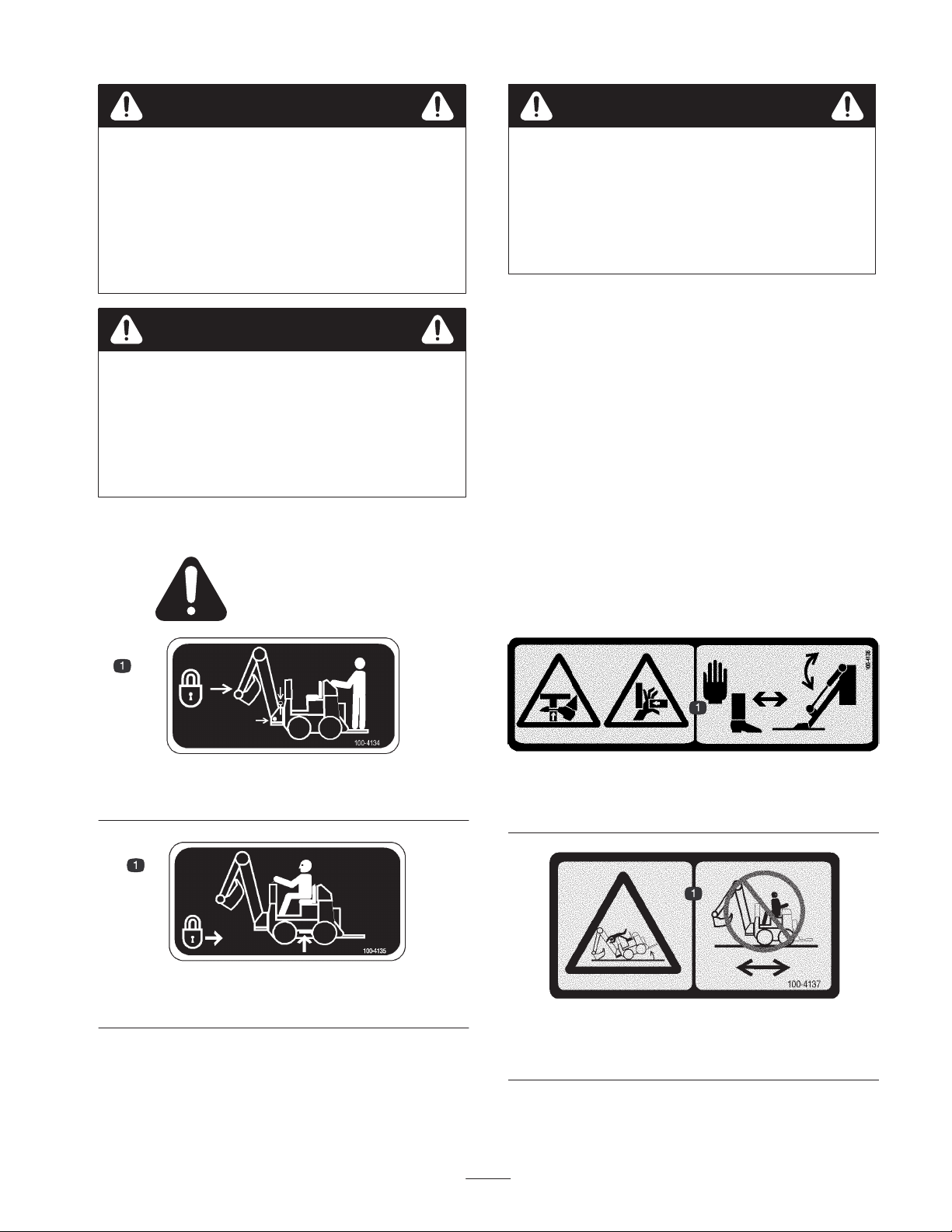
100-4134
1. Lock the boom before transporting the backhoe.
100-4135
1. Install and secure the side bars before operating the backhoe.
100-4136
1. Crushing hazard of hand and foot—keep hands and feet a safe
distance from a moving stabilizer.
100-4137
1. Tipping hazard—do not move the traction unit while seated on
the backhoe.
3
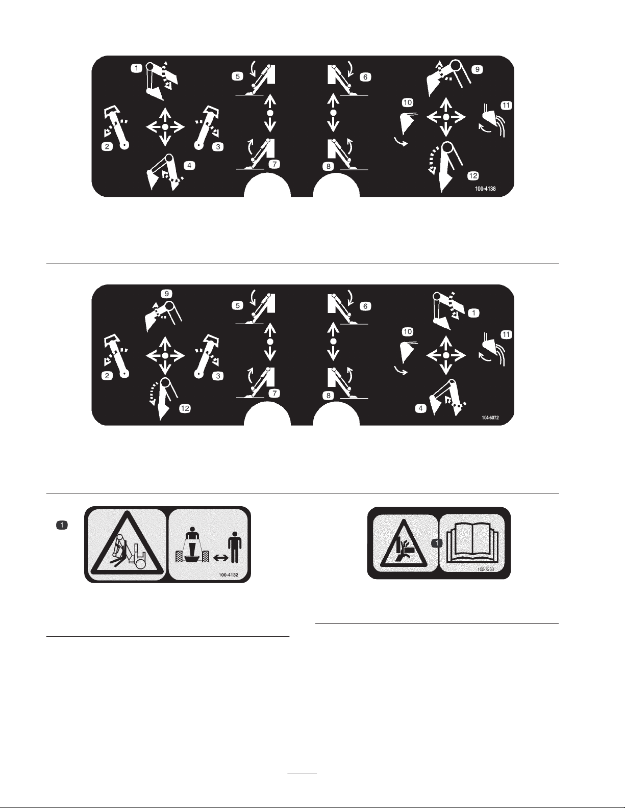
1. Lower the boom.
2. Rotate the boom left.
3. Rotate the boom right.
1. Lower the boom.
2. Rotate the boom left.
3. Rotate the boom right.
4. Raise the boom.
5. Lower the left stabilizer.
6. Lower the right stabilizer.
100-4138 (CE only)
4. Raise the boom.
5. Lower the left stabilizer.
6. Lower the right stabilizer.
100-4138
7. Raise the left stabilizer.
8. Raise the right stabilizer.
9. Raise the dipperstick.
7. Raise the left stabilizer.
8. Raise the right stabilizer.
9. Raise the dipperstick.
10. Curl the bucket.
11. Dump the bucket.
12. Lower the dipperstick.
10. Curl the bucket.
11. Dump the bucket.
12. Lower the dipperstick.
100-4132
1. Crushing hazard, backhoe—keep bystanders a safe distance
from the backhoe.
100-7263
1. Crushing hazard of hand—read the
4
Operator’s Manual.
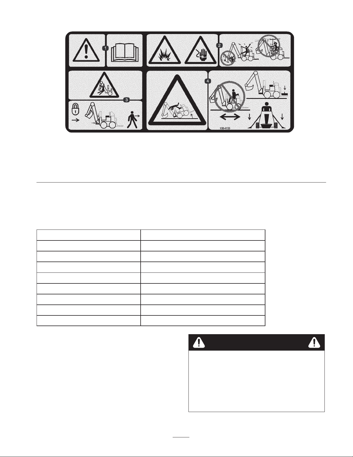
100-4133
1. Warning—read the
2. Explosion and electric shock hazards—do not dig in areas with buried gas or electrical lines, and do not operate under overhead electrical
lines.
3. Crushing hazard, backhoe—lock the boom before leaving the machine.
4. Tipping hazard—do not move the traction unit while seated on the backhoe, install the counter–weight, and lower the stabilizers.
Operator’s Manual.
Specifications
Note: Specifications and design are subject to change without notice.
Width 34.5 inches (87.6 cm)
Length 112.5 inches (286 cm)
Transport height 84 inches (213 cm)
Fully raised height 115 inches (292 cm)
Weight 710 lbs (322 Kg)
Digging depth (maximum) 79 inches (200.6 cm)
Bucket rotation 135 degrees
Swing arc 151 degrees
Stabilizer spread (working) 130 inches (330 cm)
Stability Ratings
To determine the degree of slope you can traverse with the
backhoe installed on a traction unit, find the stability rating
for the hill position you want to travel in the following
table, then find the degree of slope for the same rating and
hill position in the Stability Data section of the traction unit
operator’s manual.
5
Warning
Exceeding the maximum recommended slope can
cause the traction unit to tip, crushing you or
bystanders.
Do not drive the traction unit on a slope steeper
than the maximum recommended slope, as
determined in the following table and the traction
unit operator’s manual.
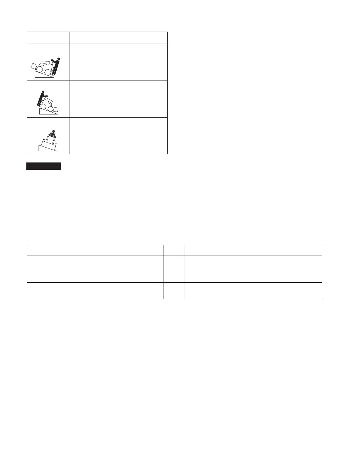
Orientation
Front Uphill
Stability Rating
C
Rear Uphill
D
Side Uphill
C
Important If your traction unit has a rear operator’s
platform, the counterweight must be used on the platform
while using the backhoe, or the traction unit will become
unstable.
Setup
Loose Parts
Note: Use the chart below to identify parts for assembly.
DESCRIPTION QTY. USE
Dingo 200/300 Series Backhoe Kit (sold
separately)
Dingo TX Backhoe Kit (sold separately)
Bucket, 9, 12, or 16 inch (23, 30, or 41 cm) 1
The backhoe mounts slightly differently to the Dingo 200/300 series traction unit than it does to the Dingo TX. If you will be
using the backhoe on a Dingo 200/300 series traction unit, install the Dingo 200/300 Series Backhoe Kit on your traction unit.
If you will be using the backhoe on a Dingo TX traction unit, install the Dingo TX Backhoe Kit on your traction unit. Use
the instructions provided in this section to install these kits.
Installing the Dingo 200/300
Series Backhoe Kit
If you will be using the backhoe with a Dingo 200 or 300
series traction unit, install the side bar brackets and tilt
cylinder pin included in the Dingo 200/300 Series Backhoe
Kit.
1
1
One kit required to connect the backhoe to your
traction unit
Install on the backhoe. Must be purchased
separately.
Installing the Side Bar Brackets
1. Remove the traction unit manual holder and relocate it
under the control panel (models 22305 and 22305TE
only).
2. Remove the battery from the traction unit. Refer to
your traction unit operator’s manual.
Note: If you have a Dingo 300 series, diesel traction unit,
you do not need to remove the battery; however, you do
need to remove the loader arm cylinder and exhaust cover
plate on the right side of the machine. To remove the
loader arm cylinder, you need to raise the loader arms and
6
 Loading...