

Toro 23160 Parts Catalogue

Backhoe
Form Number 3352-378
Ordering Replacement Parts
Dingo
®
Compact Utility Loader
Model No. 23160 - 240000146 and up.
Parts Catalog
To order replacement parts, please supply the part
number, the quantity, and the description of each
part desired.
Understanding Reference Numbers
Each Identified part in an illustration has a reference
number. The reference number for a part also
appears in the parts list, along with other information
about the part.
This catalog uses two special reference number
formats, one to indicate parts in a service assembly
and another to indicate the quantity of a given part in
an illustration.
Service Assembly Reference Numbers
Parts in service assemblies have reference numbers
in the form a:b. The a represents the reference
number of the entire service assembly and the b
represents a sequential number unique to each part
within the service assembly.
For example, a wheel assembly might be identified
by reference number 6, the tire by 6:1, the valve by
6:2, and the wheel by 6:3. When you order the
assembly identified by reference number 6, you
receive all parts identified by reference numbers 6:1,
6:2, and 6:3. However, you may also order any part
individually. Reference numbers of this type appear
in illustrations and in part lists.
Reference Numbers Indicating Quantity
In an illustration, if a reference number indicates
more than one part, the reference number has the
form nX y. The n represents the quantity of the part,
the X is the multiplication symbol, and the y
represents the reference number.
For example, in an illustration, the reference number
2X 37 means that two of the parts identified by
reference number 37 are indicated.
2004©The Toro Company -
All Rights Reserved

Contents
Description Page
. . . . . . 3Crown Arm and Linkage Assembly
. . . . . . 4Frame, Boom and Stabilizer Assembly
. . . . . . 5Seat and Mounting Assembly
. . . . . . 6Cylinder and Control Assembly
Description Page
Part Description Abbreviations
Part descriptions in this catalog may include the following abbreviations.
AR. . . . . . . . . . . . . . . as required
ASM. . . . . . . . . . . . . . assembly
CARR. . . . . . . . . . . . carriage
DEG. . . . . . . . . . . . . . degrees
FH. . . . . . . . . . . . . . . flat head
GA. . . . . . . . . . . . . . . gauge
HF. . . . . . . . . . . . . . . hex flange
HH. . . . . . . . . . . . . . . hex head
HHF. . . . . . . . . . . . . . hex head flange
HHFTF. . . . . . . . . . . . hex head flange thread forming
HJ. . . . . . . . . . . . . . . hex jam
HLH. . . . . . . . . . . . . . hex lag head
HOC. . . . . . . . . . . . . . height-of-cut
HS. . . . . . . . . . . . . . . hex
HSBH. . . . . . . . . . . . . hex socket button head
HSFH. . . . . . . . . . . . . hex socket flat head
HSH. . . . . . . . . . . . . . hex socket head
HWH. . . . . . . . . . . . . hex washer head
HWHTF. . . . . . . . . . . hex washer head thread forming
HYD. . . . . . . . . . . . . . hydraulic
INC. . . . . . . . . . . . . . . incorporated
LH. . . . . . . . . . . . . . . left hand
NI. . . . . . . . . . . . . . . . nylon insert
PPH. . . . . . . . . . . . . . phillips pan head
PTH. . . . . . . . . . . . . . phillips truss head
PTO. . . . . . . . . . . . . . power take off
RH. . . . . . . . . . . . . . . right hand
SFH. . . . . . . . . . . . . . slotted fillister head
SHH. . . . . . . . . . . . . . slotted hex head
SHWH. . . . . . . . . . . . slotted hex washer head
SPH. . . . . . . . . . . . . . slotted pan head
SQH. . . . . . . . . . . . . . square head
SRH. . . . . . . . . . . . . . slotted round head
STD. . . . . . . . . . . . . . standard
TAP. . . . . . . . . . . . . . self tapping
TTH. . . . . . . . . . . . . . torx truss head
WH. . . . . . . . . . . . . . .wing head
. . . . . . 7Valve Assembly No. 100-7205
. . . . . . 8Hydraulic Assembly
. . . . . . 9Hydraulic Fitting and Tooth Assembly
Footnotes
Œ
Not illustrated
2
3352-378
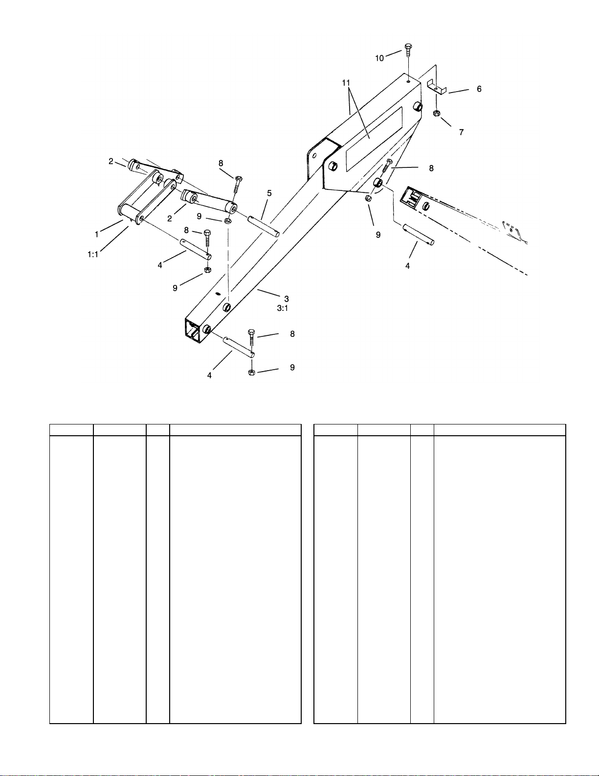
Crown Arm and Linkage Assembly
Ref Part No. Qty. Description
Linkage ASM1
100-7163
302-19
100-7160
100-7155
302-19
100-7170
100-7171
100-7183
3296-29
321-33
32146-17
322-7
62-7400
1
Fitting-Grease1:1
3
Linkage Strap ASM2
2
Crowd Arm ASM3
1
Fitting-Grease3:1
2
Pin-Bucket4
3
Pin-Linkage5
2
Bracket-Hose6
1
Nut-Lock, NI7
1
Screw-HH8
8
Nut-Lock9
8
Screw-HH10
1
Decal11
2
3
3352-378
3
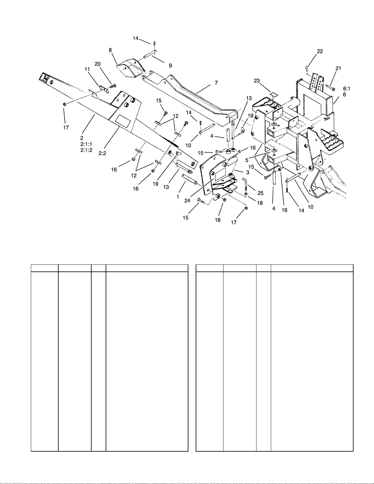
Frame, Boom and Stabilizer Assembly
Ref Part No. Qty. Description
Pin-Bucket1
16
28
2
Boom ASM2
1
Fitting-Grease2:1:1
1
Fitting-Grease2:1:2
1
Decal-Warning2:2
2
Swivel ASM3
1
Pin-Pivot4
2
Washer-Thrust5
2
Box Frame ASM6
1
Fitting-Grease6:1
2
Stabilizer ASM7
2
Stabilizer Foot ASM8
2
Pin-Foot, Stabilizer9
2
Pin-Stabilizer10
4
Bracket-Hose11
1
Bracket-Hose12
4
Lock Pin ASM13
2
Pin-Roll14
Screw-HH15
Nut-Lock16
4
Nut-Lock, NI17
4
Nut-Hex18
2
Pin-Lynch19
6
Screw-HH20
1
100-7170
100-7215
Œ
Œ
Œ
302-19
302-60
100-4132
100-7156
100-7175
100-7187
100-7151
302-19
100-7153
100-7161
100-7184
100-7185
100-7183
100-7182
100-7164
32121-15
321-33
32146-17
3296-29
3217-6
283-72
322-7
4
Ref Part No. Qty. Description
Pin-Clevis21
100-7209
3290-355
100-7263
100-4134
100-7222
1
Pin-Hair22
1
Decal-Warning23
2
Decal-Pin Placement24
2
Bracket-Hose25
2
 Loading...