


ConcreteBreaker
23136
Betonbrecher
23136
Martillohidráulico
23136
Brise-béton
23136
Betonbreker
FormNo.3447-325RevA
23136
www.T oro.com.
*3447-325*


FormNo.3447-314RevA
ConcreteBreaker
CompactToolCarriers
ModelNo.23136—SerialNo.321000001andUp
Registeratwww.T oro.com.
OriginalInstructions(EN)
*3447-314*

WARNING
CALIFORNIA
Proposition65Warning
Useofthisproductmaycauseexposure
tochemicalsknowntotheStateof
Californiatocausecancer,birthdefects,
orotherreproductiveharm.
Introduction
Thisconcretebreakerisintendedtobeusedona
Torocompacttoolcarrier.Itisdesignedprimarily
forbreakingconcrete,asphalt,rock,orbrickduring
renovationjobs.
Readthisinformationcarefullytolearnhowtooperate
andmaintainyourproductproperlyandtoavoid
injuryandproductdamage.Y ouareresponsiblefor
operatingtheproductproperlyandsafely .
Visitwww.Toro.comforproductsafetyandoperation
trainingmaterials,accessoryinformation,helpnding
adealer,ortoregisteryourproduct.
Wheneveryouneedservice,genuinethe
manufacturerparts,oradditionalinformation,contact
anAuthorizedServiceDealerorthemanufacturer
CustomerServiceandhavethemodelandserial
numbersofyourproductready .Themodelandserial
numbersareprintedonaplatelocatedontheright
sideofthedrivehead.Writethenumbersinthespace
provided.
Important:Withyourmobiledevice,youcan
scantheQRcodeontheserialnumberdecal(if
equipped)toaccesswarranty,parts,andother
productinformation.
g360512
Figure1
1.Modelandserialnumberlocation
ModelNo.
SerialNo.
Thismanualidentiespotentialhazardsandhas
safetymessagesidentiedbythesafety-alertsymbol
(Figure2),whichsignalsahazardthatmaycause
seriousinjuryordeathifyoudonotfollowthe
recommendedprecautions.
g000502
Figure2
1.Safety-alertsymbol
Thismanualuses2wordstohighlightinformation.
Importantcallsattentiontospecialmechanical
informationandNoteemphasizesgeneralinformation
worthyofspecialattention.
©2021—TheToro®Company
8111LyndaleAvenueSouth
Bloomington,MN55420
Contactusatwww.Toro.com.
2
PrintedintheUSA
AllRightsReserved

Contents
Safety.......................................................................3
GeneralSafety...................................................3
SlopeSafety.......................................................4
ConcreteBreakerSafety....................................4
MaintenanceandStorageSafety........................4
SafetyandInstructionalDecals..........................5
Setup........................................................................6
1InstallingtheBit...............................................6
ProductOverview.....................................................6
Specications....................................................6
Attachments/Accessories...................................6
Operation..................................................................7
InstallingandRemovingtheAttachment.............7
SelectingaTool..................................................7
ReplacingtheBit................................................7
TestingtheBreaker.............................................9
BreakingMaterial.............................................10
BreakingaVerticalSurface...............................10
TransportPosition............................................10
OperatingTips..................................................11
Maintenance...........................................................12
RecommendedMaintenanceSchedule(s)...........12
GreasingtheBit................................................12
CheckingtheNitrogenCharge..........................13
CheckingtheHydraulicLines...........................13
Storage...................................................................14
StoringtheAttachment.....................................14
Troubleshooting......................................................15
Safety
DANGER
Theremaybeburiedutilitylinesinthework
area.Diggingintothemmaycauseashock
oranexplosion.
Havethepropertyorworkareamarkedfor
buriedlinesanddonotdiginmarkedareas.
Contactyourlocalmarkingserviceorutility
companytohavethepropertymarked(for
example,intheUS,call811orinAustralia,
call1100forthenationwidemarkingservice).
GeneralSafety
Alwaysfollowallsafetyinstructionstoavoidserious
injuryordeath.
•Donottransportanattachmentwiththearms
raised.Alwaystransporttheattachmentcloseto
theground;refertoTransportPosition(page10).
•Havethepropertyorworkareamarkedforburied
linesandotherobjects,anddonotdiginmarked
areas.
•ReadandunderstandthecontentofthisOperator’s
Manualbeforestartingtheengine.
•Useyourfullattentionwhileoperatingthe
machine.Donotengageinanyactivitythat
causesdistractions;otherwise,injuryorproperty
damagemayoccur.
•Neverallowchildrenoruntrainedpeopleto
operatethemachine.
•Keepyourhandsandfeetawayfromthemoving
componentsandattachments.
•Donotoperatethemachinewithouttheguards
andothersafetyprotectivedevicesinplaceand
workingonthemachine.
•Keepbystandersandpetsawayfromthemachine.
•Stopthemachine,shutofftheengine,andremove
thekeybeforeservicing,fueling,orunclogging
themachine.
Improperlyusingormaintainingthismachinecan
resultininjury.T oreducethepotentialforinjury,
complywiththesesafetyinstructionsandalways
payattentiontothesafety-alertsymbol
meansCaution,Warning,orDanger—personalsafety
instruction.Failuretocomplywiththeseinstructions
mayresultinpersonalinjuryordeath.
,which
3

SlopeSafety
•Operatethemachineupanddownslopeswith
theheavyendofthemachineuphill.Weight
distributionchangeswithattachments.This
attachmentmakesthefrontofmachinetheheavy
end.
•Keeptheattachmentintheloweredposition
whenonslopes.Raisingtheattachmentona
slopeaffectsthestabilityofthemachine.
•Slopesareamajorfactorrelatedtolossofcontrol
andtip-overaccidents,whichcanresultinsevere
injuryordeath.Operatingthemachineonany
slopeoruneventerrainrequiresextracaution.
•Establishyourownproceduresandrulesfor
operatingonslopes.Theseproceduresmust
includesurveyingthesitetodeterminewhich
slopesaresafeformachineoperation.Always
usecommonsenseandgoodjudgmentwhen
performingthissurvey.
•Slowdownanduseextracareonhillsides.Ground
conditionscanaffectthestabilityofthemachine.
•Avoidstartingorstoppingonaslope.Ifthe
machinelosestraction,proceedslowly,straight
downtheslope.
•Avoidturningonslopes.Ifyoumustturn,turn
slowlyandkeeptheheavyendofthemachine
uphill.
•Keepallmovementsonslopesslowandgradual.
Donotmakesuddenchangesinspeedor
direction.
•Ifyoufeeluneasyoperatingthemachineona
slope,donotdoit.
•Watchforholes,ruts,orbumps,asuneventerrain
couldoverturnthemachine.T allgrasscanhide
obstacles.
•Usecautionwhenoperatingonwetsurfaces.
Reducedtractioncouldcausesliding.
•Evaluatetheareatoensurethatthegroundis
stableenoughtosupportthemachine.
•Usecautionwhenoperatingthemachinenearthe
following:
–Drop-offs
–Ditches
–Embankments
–Bodiesofwater
Themachinecouldsuddenlyrolloverifatrack
goesovertheedgeortheedgecavesin.Maintain
asafedistancebetweenthemachineandany
hazard.
ConcreteBreakerSafety
•Wearpersonalprotectiveequipment(PPE)and
appropriateclothing,includingthefollowing:
–Hardhat
–Respiratorordustmask
–Safetyglasses
–Hearingprotection
–Substantial,slip-resistantfootwear
–Longpants
–Shirtwithlongsleevesthataretightatthe
wrists
–Tight-ttinggloveswithoutdrawstringsorloose
cuffs
•Forwheeledtractionunits,usethecounterweight
whenusingtheattachment.
•Keepthetractionunitawayfromtheedgebeing
broken.
•Donotbreakmaterialdirectlyunderthefrontof
thetractionunit.
•Withinthebreakerisachambercontaining
pressurizednitrogen,whichundertheright
circumstancescouldexplode.Donotdisassemble
thebodyofthebreaker.
•Donotattempttochargethecushionchamber
yourself.ContactyourAuthorizedServiceDealer
forcharging.
•Ensurethatthebreakerischargedonlywith
nitrogen.
•Donotshipthechargedbreakerviaairfreight.
MaintenanceandStorage
Safety
•Checkfastenersatfrequentintervalsforproper
tightnesstoensurethattheequipmentisinsafe
operatingcondition.
•RefertothisOperator’sManualforimportant
detailsifyoustoretheattachmentforanextended
periodoftime.
•Maintainorreplacesafetyandinstructionlabels,
asnecessary.
•Donotremoveoraddattachmentsonaslope.
•Donotparkthemachineonahillsideorslope.
4

SafetyandInstructional
Decals
Safetydecalsandinstructionsareeasilyvisibletotheoperatorandarelocatednearanyarea
ofpotentialdanger.Replaceanydecalthatisdamagedorlost.
133-8061
145-3751
1.ReadtheOperator’sManual;greasethemachineevery3
hours.
decal133-8061
decal145-3751
decal145-3753
145-3753
145-3752
1.Warning—Maximumpressure8bar(116psi);readthe
Operator’sManual.
1.Warning—readthe
Operator’sManual.
decal145-3752
2.Thrownobject
hazard—keepbystanders
away
3.Cutting/dismemberment
hazardofhand—stay
awayfrommovingparts.
4.Warning—wearhearing,
eye,andrespiratory
protection.
5.ExplosionandElectric
shockhazard—donot
operatethemachine;call
yourlocalutilitycompany.
5

Setup
ProductOverview
1
InstallingtheBit
NoPartsRequired
Procedure
RefertoInstallingtheBit(page8).
Specications
Note:Specicationsanddesignaresubjectto
changewithoutnotice.
Width
Length
Height
Weight
Bitworkinglength
Bitdiameter
Impactenergyclass
Impactrate600to1 150bpm
Flowrange
Attachments/Accessories
Aselectionofthemanufacturerapprovedattachments
andaccessoriesisavailableforusewiththemachine
toenhanceandexpanditscapabilities.Contact
yourAuthorizedServiceDealerorauthorizedthe
manufacturerdistributororgotowww.T oro.comfora
listofallapprovedattachmentsandaccessories.
63cm(24.8inches)
130cm(51.2inches)
33cm(13.0inches)
176kg(389lb)
29cm(1 1.4inches)
5cm(2inches)
339J(250ft-lb)
20to35Lperminute(5.3to
8.2USgallonsperminute)
Toensureoptimumperformanceandcontinuedsafety
certicationofthemachine,useonlygenuineToro
replacementpartsandaccessories.Replacement
partsandaccessoriesmadebyothermanufacturers
couldbedangerous,andsuchusecouldvoidthe
productwarranty.
6

Operation
Important:For300seriestractionunits,ensure
thatyouinstalltheReliefValveKitonyourtraction
unitbeforeusingthebreaker.Failuretoinstallthe
kitmaydamageyourtractionunit.Refertoyour
AuthorizedServiceDealerformoreinformation.
InstallingandRemoving
theAttachment
CAUTION
Hydrauliccouplers,hydrauliclines/valves,
andhydraulicuidmaybehot.Ifyoucontact
hotcomponents,youmaybeburned.
•Weargloveswhendisconnectingthe
hydrauliccouplers.
•Allowthemachinetocoolbeforetouching
hydrauliccomponents.
•Donottouchhydraulicuidspills.
RefertotheOperator’sManualforthetractionunitfor
theinstallationandremovalprocedure.
Important:Beforeinstallingtheattachment,
positionthemachineonalevelsurface,ensure
thatthemountplatesarefreeofanydirtordebris,
andensurethatthepinsrotatefreely .Ifthepins
donotrotatefreely,greasethem.
Note:Alwaysusethetractionunittoliftandmove
theattachment.
WARNING
Ifyoudonotfullyseatthequick-attach
pinsthroughtheattachmentmountplate,
theattachmentcouldfalloffthemachine,
crushingyouorbystanders.
Ensurethatthequick-attachpinsarefully
seatedintheattachmentmountplate.
WARNING
Hydraulicuidescapingunderpressurecan
penetrateskinandcauseinjury.Fluidinjected
intotheskinmustbesurgicallyremoved
withinafewhoursbyadoctorfamiliarwith
thisformofinjury;otherwise,gangrenemay
result.
SelectingaTool
Usethefollowingtabletochoosethemostsuitable
toolforoperation:
ToolUse
ChiselUseforallearth-moving
MoilUsetodemolishrocksand
AsphaltCutter
duties,excavationsinnarrow
trenches,stratiedsoil,orrock
uptomediumrock.
materials,notstratiedrock,
uptomediumhardness.
Usetocutasphaltpaving,
brickwalls,orturf.
ReplacingtheBit
RemovingtheBit
1.Parkthemachineonalevelsurfaceandengage
theparkingbrake(ifapplicable).
2.Raisetheloaderarmsandtiltthebreakerso
thatitisvertical.
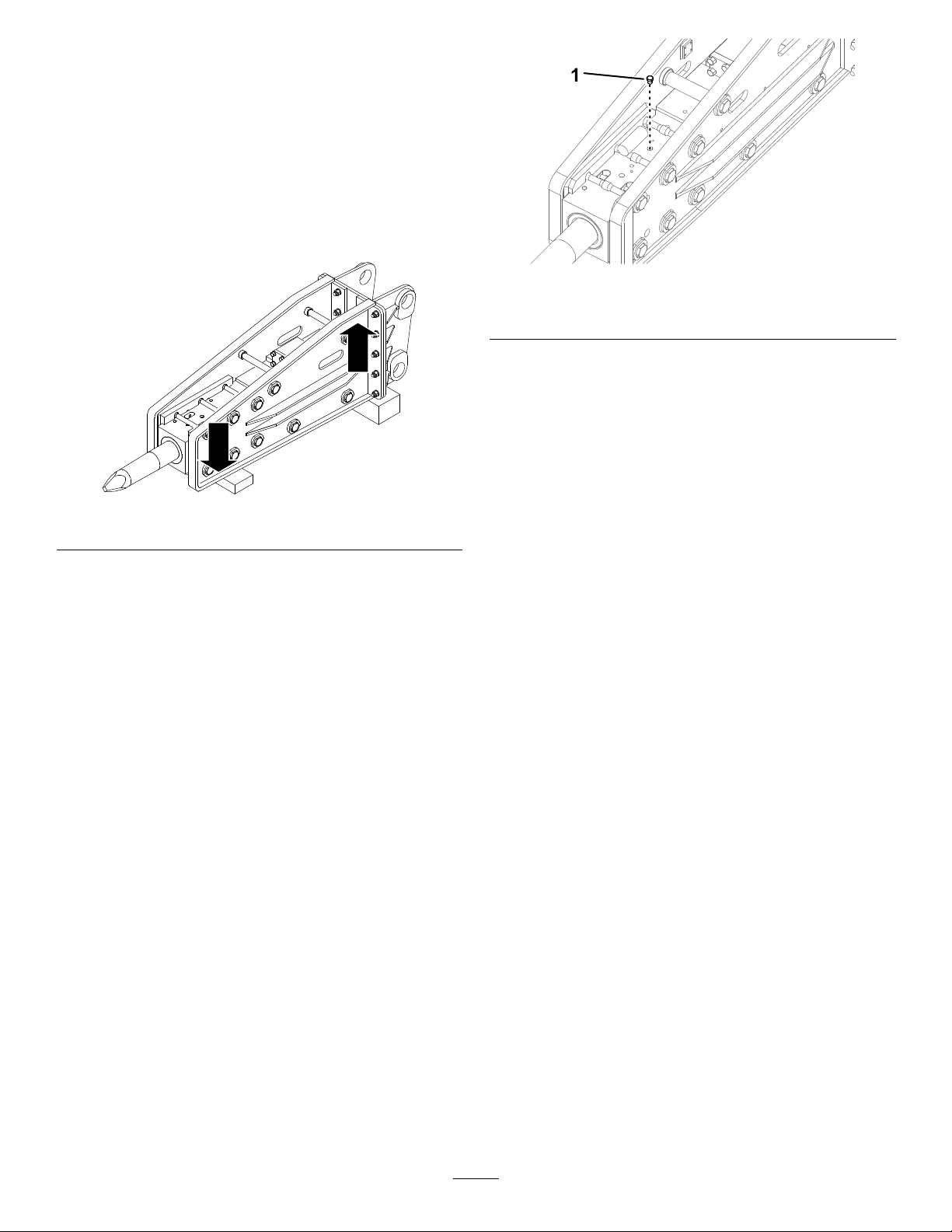
3.Lowerthebittothegroundtopushitupintothe
breakeruntilitstops.
•Ensurethatallhydraulic-uidhoses
andlinesareingoodconditionandall
hydraulicconnectionsandttingsaretight
beforeapplyingpressuretothehydraulic
system.
•Keepyourbodyandhandsawayfrom
pinholeleaksornozzlesthateject
high-pressurehydraulicuid.
•Usecardboardorpapertondhydraulic
leaks;neveruseyourhands.
g359140
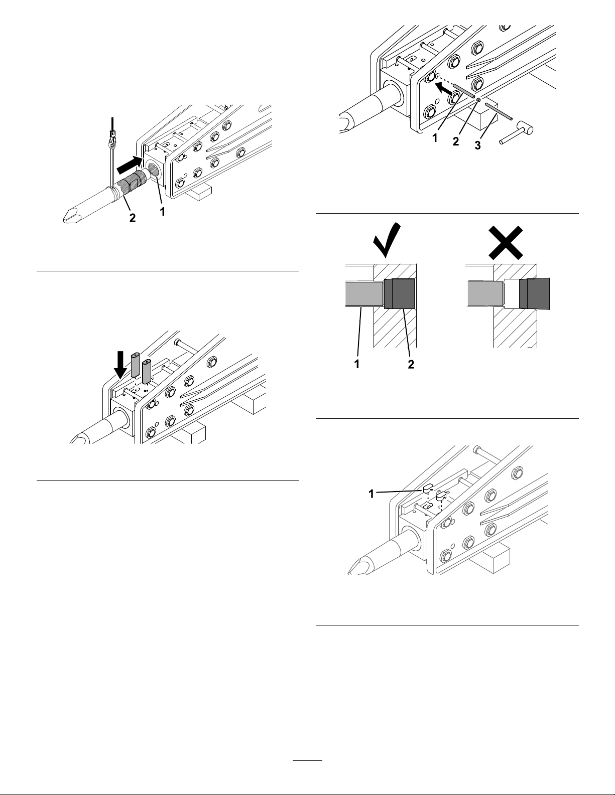
Figure3
4.Shutofftheengineandremovethekey.
5.Installthecylinderlocks.
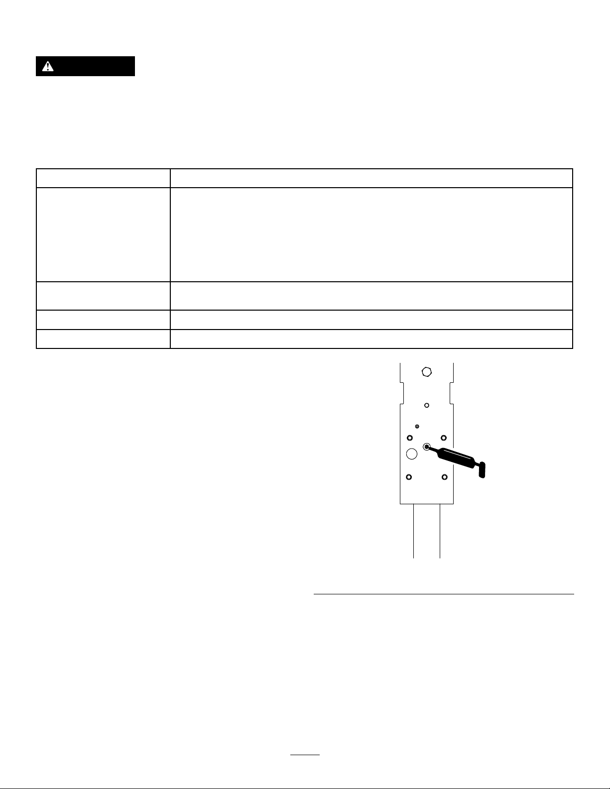
6.Useahammerandthebitpinremoverto
removethestopperplugandstopperpin.
7

12.Removethebit.
Figure4
1.Bitpinremover
2.Stopperpin
3.Stopperplug
7.Fromtheoppositesideoftheretainerpinplugs,
useahammerandthebitpinremovertoremove
the2retainerpinplugs.
Note:Donotremovetheretainerpins;
otherwisethebitmayfallout.
Figure5
g358958
g359828
Figure7
InstallingtheBit
1.Ensurethattheconcretebreakerrestsonthe
ground.
2.Greasethebitandinsideofthebitbushing.
g358954
Figure8
g359829
1.Bitbushing2.Bit
1.Bitpinremover
2.Retainerpinplug(2)
8.Removetheloaderarmcylinderlocks.
9.Lowertheloaderarmsandplacethebreaker
onwoodenblocks.
10.Shutofftheengineandremovethekey.
11.Usethebitpinremoverfromunderneaththe
retainerpinstoremovethepins.
Figure6
3.Insertthebitintothebreakerhousing.
4.Installthe2retainingpins.
g358955
Figure9
5.Useahammerandbitpinremovertoinstallthe
stopperpinandstopperplug.
g359830
Important:Ensurethatthestopperplugis
fullyinsertedinthehousingasshownin
Figure11.
8

1.Stopperpin
2.Stopperplug
Figure10
TestingtheBreaker
Important:Afterinstallingthebreakerona
machine,especiallyafterstorage,alwaystestit
beforeyoubreakmaterialtoreleaseairfromthe
oilcircuit.Usingthebreakersuddenlywithout
releasingtheairbreakstheoillmandcauses
thebreakertoseize.
1.Parkthemachineonalevelsurfaceandengage
g358956
3.Pinremover
theparkingbrake(ifapplicable).
2.Raisetheloaderarmsandtiltthebreakerso
thatitisvertical.Ensurethatthebitdoesnot
touchtheground.
Figure11
1.Stopperpin2.Stopperplug
6.Installthe2retainerpinplugs.
Figure12
1.Retainerpinplug(2)
g359139
Figure13
g358957
3.Slowlyengagetheforwardhydraulicsuntilthe
breakerpistonrises,thenslowlyreversethe
hydraulicsbeforethepistonimpacts.
Important:Donotallowthepistonto
impact.
4.Refertothetablefortestingtimesforthe2
stages.
Important:Donotallowthepistontoimpact
duringtheairremovalandsealrecovery
time.
12
Airremovaland
sealrecoverytime
g359804
Newbreaker
Afterhosesare
connected,no
repairs
Afterrepairsto
breaker
15minutes
20minutes
Preparationtime
Operatethe
machinefor
10minutesat
50%throttle
then
20minutesat
70%throttle
9

BreakingMaterial
BreakingaVerticalSurface
Important:Continuouslyimpactingthesame
locationforlongperiodsoftimecreateshigh
temperaturesatthetipofthebit.Thiscouldcause
thebittoloseitstemperandmushroomunder
impact,destroyingthebit.
1.Adjustthethrottleforyourmachineas
appropriateforbreakingmaterial:
•For300-seriesmachines,usefullthrottle
(maximumenginespeed),uselowrange
(turtleposition)onthespeed-selector
lever,andadjusttheow-dividervalveto
approximatelythe10o’clockposition.
•Fore-Dingomachines,changethe
attachmentmodetoHammerMode.
•ForTX-seriesmachines,use3/4throttle.
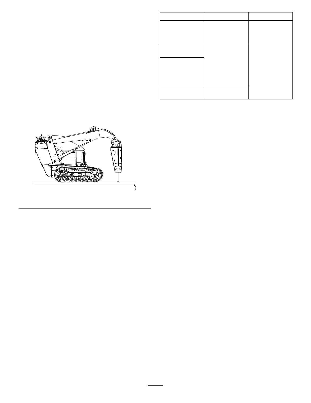
2.Placethebreakerbitwithin15to46cm(6to
18inches)fromtheedgeofthematerialtobe
broken,ata90-degreeangle.
1.Positionthebitontheverticalsurfaceinthe
samemannerasyouwouldpositionitona
horizontalsurface.
2.Maintainpressureonthebitbydrivingthe
tractionunitforwardintotheverticalsurface
whileoperatingthebreaker.
3.Periodicallylowerthebreakertoavertical
positiontoallowdebristhatmayhavecollected
inthebreakertofallout.
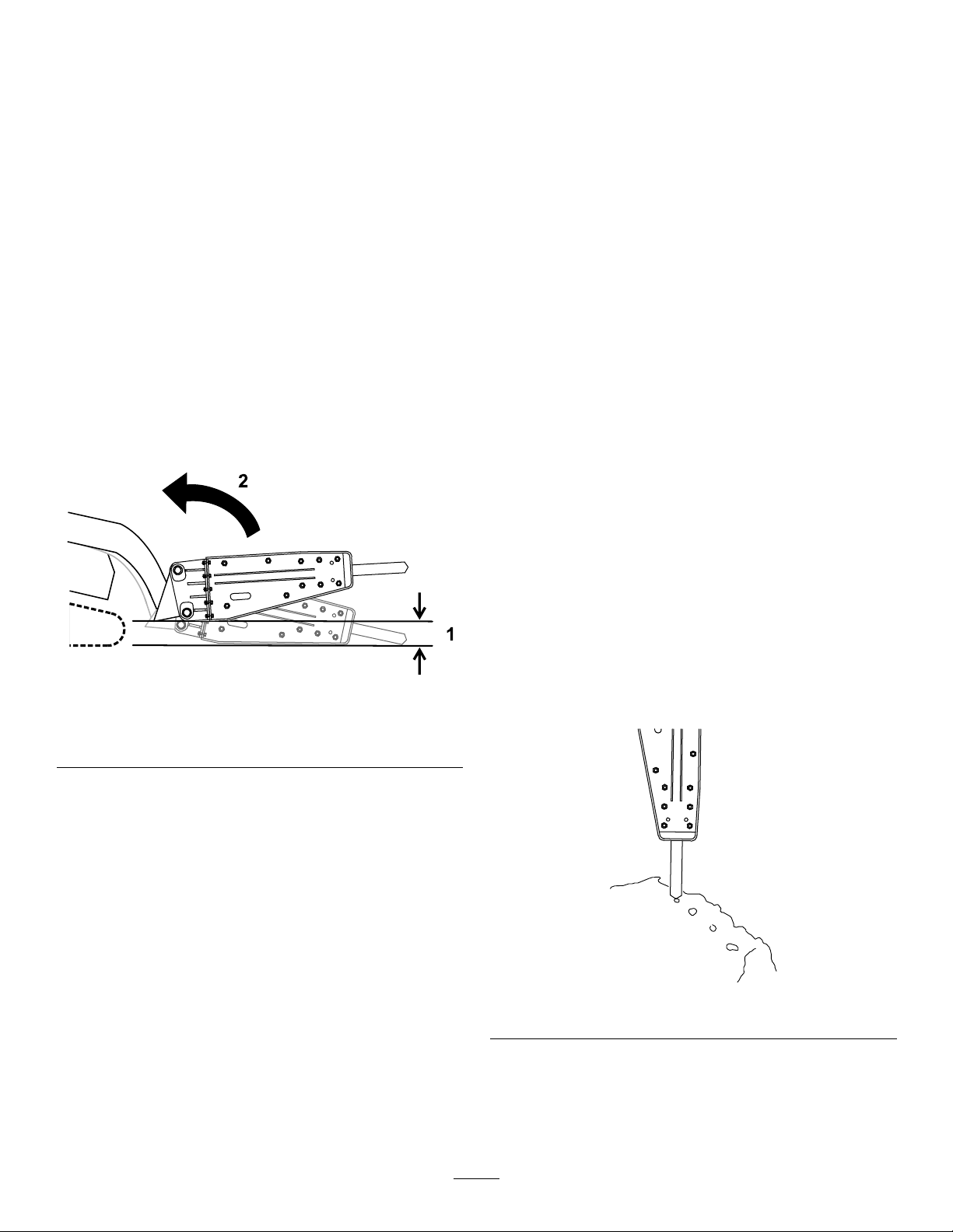
TransportPosition
Whentransportingtheattachment,keepitasclose
tothegroundaspossible,nomorethan15cm(6
inches)abovetheground.Tiltitrearward.
Figure14
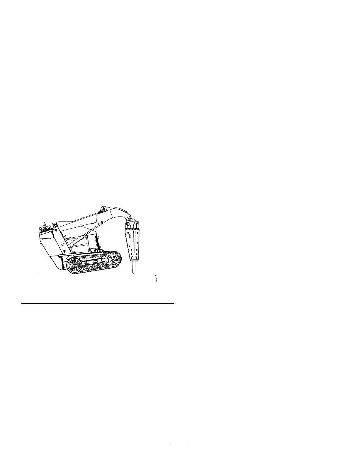
3.Applydownwardpressurewiththeloaderarms
untilthefrontofthetractionunitraisesoffthe
groundabout5cm(2inches).
Note:Donotengagethebreakerunlessthe
bitisonthegroundanddownwardpressureis
applied.
Important:Ensurethatthehydraulic
cylindershaveatleast5cm(2inches)of
stroke;donotusetheconcretebreakerwith
thehydrauliccylindersfullyextended.
4.Engagethebreakerandmaintainthedownward
pressureasthebitworksitswayintothe
materialbeingbroken.
5.Whenthematerialisbroken,immediately
disengagethehydraulicstostopstrikingthe
material.
g359749
Figure15
1.Nomorethan15cm(6
g359138
inches)abovetheground
2.Tilttheattachment
rearward.
10

OperatingTips
•Ifthebitispositionedtoofarfromtheedgeofthe
material,thematerialmayabsorbtheenergyand
notbreak.
•Ifthematerialdoesnotbreakafter1minute,stop
thebreakerandmovethebittoadifferentlocation.
•Donotbindthebitinthematerialbeing
cut,otherwisethebitmaybendorwearout
prematurely.Ensurethatallforceappliedtothe
breakerisinlinewiththebit,notsidetosideor
fronttoback.Thisrequiresfrequentadjustments
inthepositioningofthetractionunit.
•Listentothesoundofthebreakerwhenis
operating.Thesoundchangeswhendownward
pressuredecreases.Ifthedownwardpressure
fromtheunitistooweak,youwillhearmetallic
strokesfromthehammerasitincorrectlystrikes
thebit.
•Excessivedownwardpressureproducesstrong
vibrationsintheunit.
•Manymaterialsdonotbreakwellwithcontinuous
hammeringin1location.Eachtimethatthe
breakerpenetratesthematerialwithoutbreaking
it,moveittoanewlocationinalineparallelto
theedgeofthematerial,about7.6cm(3inches)
fromtheprevioushole.Thisscoresthematerial
and,ifdonerepeatedly ,breaksoffalargepiece
ofthematerial.
–Neverprywiththebitofthebreaker.
–Avoidhittingmaterialabruptlywiththebit.
–Donotusethebreakertoliftormovematerial.
–Donotoperatethebreakerunderwater;only
allowthebitintowater.
Figure16
•Ifyouarebreakingrebar-reinforcedconcrete,use
achiselbitinthebreakertocutthroughtherebars
intheconcrete.Youcanalsocuttherebarwith
atorch.
•Toimprovethelifeofthebreaker:
–Ensurethatthehydrauliccylindershaveat
least5cm(2inches)ofstroke;donotusethe
concretebreakerwiththehydrauliccylinders
fullyextended.
g359750
11

Maintenance
CAUTION
Ifyouleavethekeyintheignitionswitch,someonecouldaccidentlystarttheengineand
seriouslyinjureyouorotherbystanders.
Removethekeyfromtheignitionbeforeyoudoanymaintenance.
RecommendedMaintenanceSchedule(s)
MaintenanceService
Interval
Beforeeachuseordaily
Every40hours
Every100hours
Beforestorage
MaintenanceProcedure
•Greasethebit.Greaseevery3hoursofoperationandaftereverywashing.
•Checkthehydrauliclinesforleaks,loosettings,kinkedlines,loosemounting
supports,wear,weather,andchemicaldeterioration.
•Inspectandtightenallfasteners.
•Inspectthemountingpins,holes,bitbushing,andretainerpinsforloosenessor
wear.Reseatorreplaceasnecessary.
•Measurethebitlengthwhenpressedintothebitholder.Replacethebitifthe
measuredlengthislessthan200mm(7.8inches).
•Checkthenitrogenchargeintheaccumulator.
•Paintchippedsurfaces.
GreasingtheBit
ServiceInterval:BeforeeachuseordailyGrease
every3hoursofoperationandafter
everywashing.
Greasetype:General-purposegrease
1.Parkthemachineonalevelsurfaceandengage
theparkingbrake(ifapplicable).
2.Tiltthebreakersothatitisverticalandlowerit
tothegroundtopushthebitupintothebreaker
untilitstops.
Important:Ifyoudonotpushthebitupinto
thebreakerbeforegreasing,greasemayll
thespacebetweenthetopofthebitandthe
breakerpiston.Thiscausesthepistonto
pressurizethegreaseanddamagetheseal
whenyounextusethebreaker.
3.Shutofftheengineandremovethekey.
4.Cleanthegreasettingwitharag.
5.Connectagreaseguntothetting.
g359783
Figure17
6.Pumpgreaseintothettinguntileithergrease
beginstooozeoutofthelowerbushingand
retainingpinorpumpingthegreasegun
becomesdifcult.
7.Wipeupanyexcessgrease.
12

CheckingtheNitrogen
Charge
ServiceInterval:Every100hours—Checkthe
nitrogenchargeintheaccumulator.
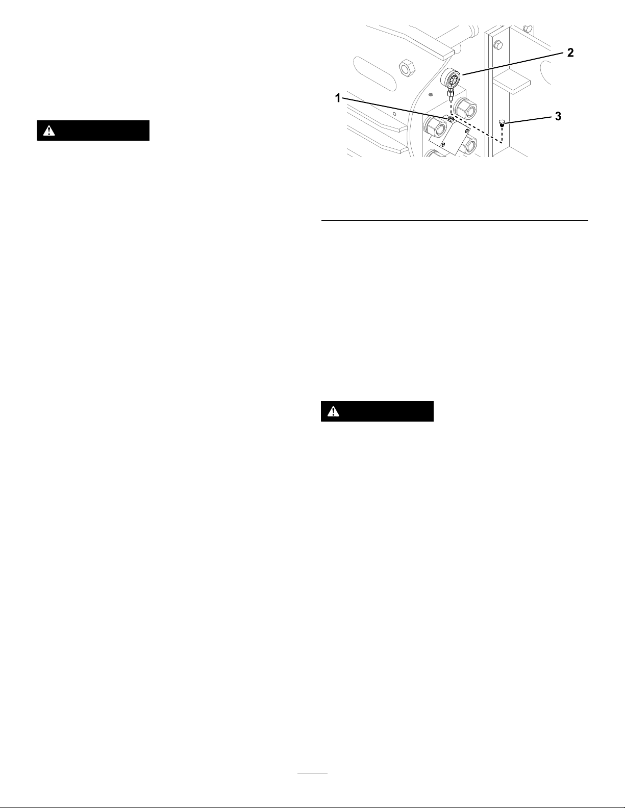
4.Insertapressuregaugeintothegasvalveand
measureit.
5.Ifitislow,contactyourAuthorizedService
Dealertochargeit.
WARNING
Withinthebreakerisachambercontaining
pressurizednitrogen,whichundertheright
circumstancescouldexplode,injuringor
killingyouorbystanders.
•Donottakeapartthebodyofthebreaker.
•Donotattempttochargethechamber
yourself.Alwaystakethebreakertoan
AuthorizedServiceDealerforcharging.
•Ensurethatthebreakerischargedonly
withnitrogen.Othergasescanexplode.
•Donotshipthechargedbreakerviaair
freight.
Insidethebreakerisanaccumulator,achamberof
pressurizednitrogen.Afterseveralhoursofusethe
pressuremaydecrease,reducingtheperformance
ofthebreaker.
Strongvibrationsintheauxiliaryhydraulichosesarea
signthepressureisdroppinginthechamber.Ifthis
shouldhappen,bringthebreakertoyourAuthorized
ServiceDealertobecharged.
CheckingtheHydraulic
Lines
ServiceInterval:Beforeeachuseordaily
WARNING
Hydraulicuidescapingunderpressurecan
penetrateskinandcauseinjury.Fluidinjected
intotheskinmustbesurgicallyremoved
withinafewhoursbyadoctorfamiliarwith
thisformofinjury;otherwise,gangrenemay
result.
•Keepyourbodyandhandsawayfrom
pinholeleaksornozzlesthateject
high-pressurehydraulicuid.
•Usecardboardorpapertondhydraulic
leaks;neveruseyourhands.
Nitrogengaspressure:8bar(116psi)
1.Parkthemachineonalevelsurface,engage
theparkingbrake(ifapplicable),andlowerthe
breakerontheground.
2.Shutofftheengineandremovethekey.
3.Removethegasvalveplugfromthecylinder
cover.
Figure18
1.Gasvalve3.Gas-valveplug
2.Pressuregauge
g359809
13

Storage
30days,releasethegaspressurefromthe
attachment:
8.Iftheattachmentwillbestoredformorethan
StoringtheAttachment
1.Parkthemachineonalevelsurfaceandengage
theparkingbrake(ifapplicable).
2.Placethebreakeron2piecesofwoodsothat
thecylindersideishigherthanthechiselholder
side.
Figure19
3.Removetheattachmentfromthemachine.
A.Removethebit;refertoRemovingtheBit
(page7)
B.Releasethenitrogengasfromthecylinder
coverthroughthegasvalve.
g359805
Figure21
1.Gasvalve
g359808
C.Placeadrainpanunderthehosesand
loosentheplugs.
4.Washtheattachmentwithmilddetergentand
watertoremovedirtandgrime.
5.Checkandtightenallbolts,nuts,andscrews.
Repairorreplaceanydamagedorwornparts.
6.Paintallscratchedorbaremetalsurfaces.Paint
isavailablefromyourAuthorizedServiceDealer.
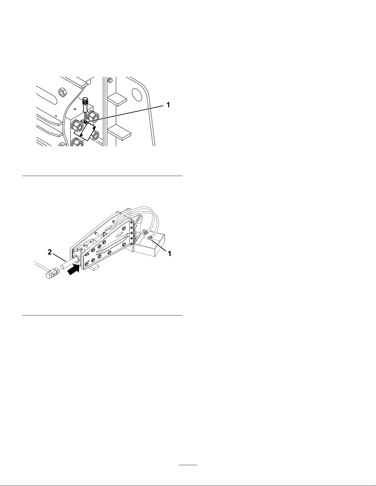
7.Removethehexplugandsprayanti-rustspray
intothepistonarea.Installthehexplug.
Figure20
1.Hexplug
g359807
Figure22
1.Hoseplug2.Rod
D.Insertarodintothepiston,andgentlypush
itinusingahammer.
Note:Thisreleasesanyexcessnitrogen
gasfromthecushionchamber.
E.Tightenthehoseplugs.
F.Greasethebitandinstallit;refertoInstalling
theBit(page8).
9.Storethebreakerinaclean,drygarageor
g359806
storagearea.Coverittoprotectitandkeepit
clean.
10.Whenremovingthebreakerfromstorage,
replacethenitrogengasbeforeoperation;
contactyourAuthorizedServiceDealer.
14

Troubleshooting
Problem
Hydraulicuidisleaking.
Morethan10bar(145psi)ofnitrogengas
leaksevery100hours.
Thebreakerdoesnotimpact.
Thebreakerimpactserratically .
PossibleCauseCorrectiveAction
1.Anoilseal,O-ring,orbackupringis
wornordamaged.
2.Thepistonorcylinderhasseized.
3.Thetierodnut,chokeplug,orhose
adapterisloose.
1.AnO-ring,piston,orsealiswornor
damaged.
2.Thepistonorcylinderhasseized.
1.Thehydraulicuidtemperatureistoo
low.
2.Thenitrogengaspressureinthe
chamberistoohigh.
3.Thestopvalveisclosed.
4.Thepressuresettingforthereliefvalve
istoolow.
5.Thehydraulicpumpisperforming
poorly.
1.Thecontrolvalve,piston,orcylinder
hasseized.
2.Thepressuresettingforthereliefvalve
istoolow.
3.Thehydraulicpumpisperforming
poorly.
4.Thereisnotenoughdownward
pressureonthebit.
5.Thenitrogengaspressureinthe
chamberistoohigh.
1.ContactyourAuthorizedService
Dealer.
2.ContactyourAuthorizedService
Dealer.
3.Tightentheloosepart.
1.ContactyourAuthorizedService
Dealer.
2.ContactyourAuthorizedService
Dealer.
1.Warmupthebreaker.
2.Releasegaspressuretothecorrect
level.
3.Openthestopvalve.
4.ContactyourAuthorizedService
Dealer.
5.ContactyourAuthorizedService
Dealer.
1.ContactyourAuthorizedService
Dealer.
2.ContactyourAuthorizedService
Dealer.
3.ContactyourAuthorizedService
Dealer.
4.Applymoredownwardpressuretothe
bit.
5.Releasegaspressuretothecorrect
level.
Thebreakerlackspower.1.Thenitrogengaspressureinthe
Thebreakerdoesnotimpact.
chamberistoolow.
1.Thenitrogengaspressureinthe
chamberistoohigh.
2.Thereisnotenoughdownward
pressureonthebit.
3.Thepressuresettingforthereliefvalve
istoolow.
4.Thehydraulicpumpisperforming
poorly.
5.Thereisanobstructioninahydraulic
hose.
1.ContactyourAuthorizedService
Dealer.
1.Releasegaspressuretothecorrect
level.
2.Applymoredownwardpressuretothe
bit.
3.ContactyourAuthorizedService
Dealer.
4.ContactyourAuthorizedService
Dealer.
5.Removetheobstructionorreplacethe
hose.
15

Notes:

Notes:

DeclarationofIncorporation
TheT oroCompany,8111LyndaleAve.South,Bloomington,MN,USAdeclaresthatthefollowingunit(s)
conform(s)tothedirectiveslisted,wheninstalledinaccordancewiththeaccompanyinginstructionsontocertain
ToromodelsasindicatedontherelevantDeclarationsofConformity.
ModelNo.
23136321000001andUp
SerialNo.
ProductDescriptionInvoiceDescription
ConcreteBreaker,Compact
ToolCarriers
HYDRAULICBREAKER,
GeneralDescription
DINGO
CompactToolCarrier2006/42/EC
RelevanttechnicaldocumentationhasbeencompiledasrequiredperPartBofAnnexVIIof2006/42/EC.
Wewillundertaketotransmit,inresponsetorequestsbynationalauthorities,relevantinformationonthispartly
completedmachinery.Themethodoftransmissionshallbeelectronictransmittal.
ThismachineryshallnotbeputintoserviceuntilincorporatedintoapprovedToromodelsasindicatedonthe
associatedDeclarationofConformityandinaccordancewithallinstructions,wherebyitcanbedeclaredin
conformitywithallrelevantDirectives.
Certied:
MichaelBenedict
EngineeringDirector
811 1LyndaleAve.South
Bloomington,MN55420,USA
July13,2021
AuthorizedRepresentative:
MarcelDutrieux
ManagerEuropeanProductIntegrity
ToroEuropeNV
Nijverheidsstraat5
2260Oevel
Belgium
Directive

EEA/UKPrivacyNotice
Toro’sUseofYourPersonalInformation
TheT oroCompany(“T oro”)respectsyourprivacy .Whenyoupurchaseourproducts,wemaycollectcertainpersonalinformationaboutyou,eitherdirectly
fromyouorthroughyourlocalT orocompanyordealer.Torousesthisinformationtofullcontractualobligations-suchastoregisteryourwarranty ,
processyourwarrantyclaimortocontactyouintheeventofaproductrecall-andforlegitimatebusinesspurposes-suchastogaugecustomer
satisfaction,improveourproductsorprovideyouwithproductinformationwhichmaybeofinterest.Toromayshareyourinformationwithoursubsidiaries,
afliates,dealersorotherbusinesspartnersinconnectiontheseactivities.Wemayalsodisclosepersonalinformationwhenrequiredbylaworin
connectionwiththesale,purchaseormergerofabusiness.Wewillneversellyourpersonalinformationtoanyothercompanyformarketingpurposes.
RetentionofyourPersonalInformation
Torowillkeepyourpersonalinformationaslongasitisrelevantfortheabovepurposesandinaccordancewithlegalrequirements.Formoreinformation
aboutapplicableretentionperiodspleasecontactlegal@toro.com.
Toro’sCommitmenttoSecurity
YourpersonalinformationmaybeprocessedintheUSoranothercountrywhichmayhavelessstrictdataprotectionlawsthanyourcountryofresidence.
Wheneverwetransferyourinformationoutsideofyourcountryofresidence,wewilltakelegallyrequiredstepstoensurethatappropriatesafeguardsare
inplacetoprotectyourinformationandtomakesureitistreatedsecurely.
AccessandCorrection
Youmayhavetherighttocorrectorreviewyourpersonaldata,orobjecttoorrestricttheprocessingofyourdata.T odoso,pleasecontactusbyemail
atlegal@toro.com.IfyouhaveconcernsaboutthewayinwhichT orohashandledyourinformation,weencourageyoutoraisethisdirectlywithus.
PleasenotethatEuropeanresidentshavetherighttocomplaintoyourDataProtectionAuthority.
374-0282RevC

CaliforniaProposition65WarningInformation
Whatisthiswarning?
Youmayseeaproductforsalethathasawarninglabellikethefollowing:
WARNING:CancerandReproductiveHarm—www.p65Warnings.ca.gov.
WhatisProp65?
Prop65appliestoanycompanyoperatinginCalifornia,sellingproductsinCalifornia,ormanufacturingproductsthatmaybesoldinorbroughtinto
California.ItmandatesthattheGovernorofCaliforniamaintainandpublishalistofchemicalsknowntocausecancer,birthdefects,and/orother
reproductiveharm.Thelist,whichisupdatedannually,includeshundredsofchemicalsfoundinmanyeverydayitems.ThepurposeofProp65isto
informthepublicaboutexposuretothesechemicals.
Prop65doesnotbanthesaleofproductscontainingthesechemicalsbutinsteadrequireswarningsonanyproduct,productpackaging,orliteraturewith
theproduct.Moreover,aProp65warningdoesnotmeanthataproductisinviolationofanyproductsafetystandardsorrequirements.Infact,the
CaliforniagovernmenthasclariedthataProp65warning“isnotthesameasaregulatorydecisionthataproductis‘safe’or‘unsafe.’”Manyofthese
chemicalshavebeenusedineverydayproductsforyearswithoutdocumentedharm.Formoreinformation,gotohttps://oag.ca.gov/prop65/faqs-view-all
AProp65warningmeansthatacompanyhaseither(1)evaluatedtheexposureandhasconcludedthatitexceedsthe“nosignicantrisklevel”;or(2)
haschosentoprovideawarningbasedonitsunderstandingaboutthepresenceofalistedchemicalwithoutattemptingtoevaluatetheexposure.
Doesthislawapplyeverywhere?
Prop65warningsarerequiredunderCalifornialawonly.ThesewarningsareseenthroughoutCaliforniainawiderangeofsettings,includingbutnot
limitedtorestaurants,grocerystores,hotels,schools,andhospitals,andonawidevarietyofproducts.Additionally ,someonlineandmailorder
retailersprovideProp65warningsontheirwebsitesorincatalogs.
.
HowdotheCaliforniawarningscomparetofederallimits?
Prop65standardsareoftenmorestringentthanfederalandinternationalstandards.TherearevarioussubstancesthatrequireaProp65warning
atlevelsthatarefarlowerthanfederalactionlimits.Forexample,theProp65standardforwarningsforleadis0.5μg/day ,whichiswellbelow
thefederalandinternationalstandards.
Whydon’tallsimilarproductscarrythewarning?
•ProductssoldinCaliforniarequireProp65labellingwhilesimilarproductssoldelsewheredonot.
•AcompanyinvolvedinaProp65lawsuitreachingasettlementmayberequiredtouseProp65warningsforitsproducts,butothercompanies
makingsimilarproductsmayhavenosuchrequirement.
•TheenforcementofProp65isinconsistent.
•CompaniesmayelectnottoprovidewarningsbecausetheyconcludethattheyarenotrequiredtodosounderProp65;alackofwarningsfora
productdoesnotmeanthattheproductisfreeoflistedchemicalsatsimilarlevels.
WhydoesToroincludethiswarning?
Torohaschosentoprovideconsumerswithasmuchinformationaspossiblesothattheycanmakeinformeddecisionsabouttheproductstheybuyand
use.T oroprovideswarningsincertaincasesbasedonitsknowledgeofthepresenceofoneormorelistedchemicalswithoutevaluatingthelevelof
exposure,asnotallthelistedchemicalsprovideexposurelimitrequirements.WhiletheexposurefromT oroproductsmaybenegligibleorwellwithinthe
“nosignicantrisk”range,outofanabundanceofcaution,T orohaselectedtoprovidetheProp65warnings.Moreover ,ifTorodoesnotprovidethese
warnings,itcouldbesuedbytheStateofCaliforniaorbyprivatepartiesseekingtoenforceProp65andsubjecttosubstantialpenalties.
RevA

FormNo.3447-316RevA
Betonbrecher
KompakteWerkzeugträger
Modellnr.23136—Seriennr.321000001undhöher
RegistrierenSieIhrProduktunterwww.Toro.com.
Originaldokuments(DE)
*3447-316*

WARNUNG:
KALIFORNIEN
WarnungzuProposition65
BeiVerwendungdiesesProduktssind
Sieggf.Chemikalienausgesetzt,
dielautdenBehördendesStaates
Kalifornienkrebserregendwirken,
GeburtsschädenoderandereDefektedes
Reproduktionssystemsverursachen.
Einführung
DieserBetonbrecheristfürdieVerwendungan
einemkompaktenToroWerkzeugträgerkonzipiert.
EristinersterLiniefürdasAufbrechenvonBeton,
Asphalt,SteineoderZiegelnbeiSanierungsarbeiten
vorgesehen.
LesenSiedieseInformationensorgfältigdurch,
umsichmitdemordnungsgemäßenEinsatzund
derWartungdesGerätsvertrautzumachenund
VerletzungenundeineBeschädigungdesGerätszu
vermeiden.SietragendieVerantwortungfüreinen
ordnungsgemäßenundsicherenEinsatzdesGeräts.
BesuchenSieToro.com,hinsichtlichProduktsicherheit
undSchulungsunterlagen,Zubehörinformationen,
StandorteinesHändlers,oderRegistrierungdes
Produkts.
g360512
Bild1
1.TypenschildmitModell-undSeriennummer
Modellnr.
Seriennr.
IndieserAnleitungwerdenpotenzielleGefahren
angeführt,undSicherheitshinweisewerdenvom
Sicherheitswarnsymbol(Bild2)gekennzeichnet.
DiesesWarnsymbolweistaufeineGefahrhin,diezu
schwerenodertödlichenVerletzungenführenkann,
wennSiedieempfohlenenSicherheitsvorkehrungen
nichteinhalten.
WendenSiesichanIhrenautorisierten
Service-VertragshändleroderKundendienst,wenn
SieeineServiceleistung,OriginalersatzteilevonToro
oderzusätzlicheInformationenbenötigen.HaltenSie
hierfürdieModell-undSeriennummernIhresProdukts
griffbereit.DieModell-undSeriennummernsindauf
einePlatteeingestanzt,diesichanderrechtenSeite
desBohrkopfesbendet.TragenSiehierdieModellundSeriennummerndesGerätsein.
Wichtig:ScannenSiemitIhremMobilgerätden
QR-CodeaufdemSeriennummernaufkleber(falls
vorhanden),umaufGarantie-,Ersatzteil-oder
andereProduktinformationenzuzugreifen.
©2021—TheToro®Company
8111LyndaleAvenueSouth
Bloomington,MN55420
Bild2
1.Sicherheitswarnsymbol
IndieserAnleitungwerdenzweiBegriffezur
HervorhebungvonInformationenverwendet.Wichtig
weistaufspeziellemechanischeInformationenhin,
undHinweishebtallgemeineInformationenhervor,
dieIhrebesondereBeachtungverdienen.
KontaktierenSieunsunterwww.Toro.com.
2
AlleRechtevorbehalten
Druck:USA
g000502

Inhalt
Sicherheit
Sicherheit..................................................................3
AllgemeineSicherheit.........................................3
SicherheitanHanglagen....................................4
SicherheitamBetonbrecher...............................5
Wartungs-undLagerungssicherheit...................5
Sicherheits-undBedienungsschilder.................6
Einrichtung................................................................7
1EinbaudesMeißels.........................................7
Produktübersicht.......................................................7
TechnischeDaten..............................................7
Anbaugeräte/Zubehör........................................7
Betrieb......................................................................8
MontierenundEntfernendes
Anbaugeräts...................................................8
AuswahleinesWerkzeugs..................................8
WechseldesMeißels..........................................9
PrüfendesBetonbrechers.................................11
Materialbrechen...............................................12
BrecheneinervertikalenFläche........................13
Transportstellung..............................................13
Betriebshinweise.............................................13
Wartung..................................................................15
EmpfohlenerWartungsplan.................................15
SchmierendesMeißels....................................15
PrüfenderStickstoffbefüllung...........................16
PrüfenderHydraulikleitungen..........................16
Einlagerung............................................................17
AufbewahrendesMeißels................................17
Fehlersucheund-behebung...................................19
GEFAHR
ImArbeitsbereichbendensichggf.
unterirdischeVersorgungsleitungen.Wenn
SiesiebeimGrabenbeschädigen,könnenSie
einenelektrischenSchlagodereineExplosion
verursachen.
MarkierenSiealleunterirdischenLeitungen
imArbeitsbereichundgrabennichtin
markiertenBereichen.KontaktierenSie
denörtlichenMarkierungsdienstoderdas
Versorgungsunternehmen,umdasGelände
richtigzumarkieren(rufenSiez.B.inden
USA811oderinAustralien1100fürden
nationalenMarkierungsdienstan).
AllgemeineSicherheit
BefolgenSiezumVermeidenvonschweren
odertödlichenVerletzungenimmersämtliche
Sicherheitshinweise.
•TransportierenSiemitangehobenenArmen
keinAnbaugerät.TransportierenSiedas
AnbaugerätimmernaheüberdemBoden,siehe
Transportstellung(Seite13).
•MarkierenSiealleunterirdischenLeitungenund
andereObjekteimArbeitsbereichundgrabenSie
nichtinmarkiertenBereichen.
•LesenundverstehenSievordemAnlassendes
MotorsdenInhaltdieserBedienungsanleitung.
•KonzentrierenSiesichimmerbeiderVerwendung
derMaschine.TunSienichts,wasSieablenken
könnte,sonstkönnenVerletzungenoder
Sachschädenauftreten.
•LassenSieniezu,dassKinderodernicht
geschultePersonendieMaschineverwenden.
•BerührenSiekeinebeweglichenTeileund
AnbaugerätemitdenHändenundFüßen.
•SetzenSiedieMaschinenieohnemontierteund
funktionierendeSchutzvorrichtungenundandere
Sicherheitseinrichtungenein.
•HaltenSieUnbeteiligteundHaustierewährend
desBetriebsvonderMaschinefern.
•HaltenSiedieMaschinean,stellenSieden
MotorabundziehenSiedenSchlüsselab,bevor
SieWartungsarbeitendurchführen,Kraftstoff
nachfüllenoderVerstopfungenanderMaschine
entfernen.
DerunsachgemäßeEinsatzoderdiefalscheWartung
dieserMaschinekannzuVerletzungenführen.
BefolgenSiezurVerringerungdesVerletzungsrisikos
dieseSicherheitshinweiseundbeachtenSiedas
3

WarnsymbolmitderBedeutungAchtung,Warnung
oderGefahr–Sicherheitsrisiko.WenndieseHinweise
nichtbeachtetwerden,kanneszuschwerenbis
tödlichenVerletzungenkommen.
SicherheitanHanglagen
•SetzenSiedieMaschinebeimArbeiten
anHanglagensoein,dassdasschwere
EndederMaschinehangaufwärtsist.Die
GewichtsverteilungändertsichmitAnbaugeräten.
DiesesAnbaugerätmachtdieVorderseiteder
MaschinezumschwerenEnde.
•HaltenSiedasAnbaugerätanHanglageninder
abgesenktenStellung.WennSiedasAnbaugerät
aneinerHanglageanheben,kannsichdiesauf
dieStabilitätderMaschineauswirken.
•HanglagensindeinewesentlicheUrsachefür
denVerlustderKontrolleundUmkippunfälle,die
zuschwerenggf.tödlichenVerletzungenführen
können.DasEinsetzenderMaschineaneiner
HanglageundaufunebenemTerrainerfordert
großeVorsicht.
•ErstellenSieIhreeigenenSchritteundRegeln
fürdasArbeitenanHanglagen.DieseSchritte
müsseneineOrtsbegehungbeinhalten,um
dieHanglagenfüreinensicherenBetriebder
Maschinezubestimmen.SetzenSieimmer
gesundenMenschenverstandein,wennSiediese
Ortsbegehungdurchführen.
•FahrenSieanHängenlangsamerundmiterhöhter
Vorsicht.DerBodenzustandkannsichaufdie
StabilitätderMaschineauswirken.
•VermeidenSiedasStartenundAnhaltenan
Hanglagen.WenndieMaschinedieBodenhaftung
verliert,fahrenSielangsamhangabwärts.
•VermeidenSiedasWendenanHanglagen.Wenn
SiebeimArbeitenanHängenwendenmüssen,
wendenSielangsamundhaltenSiedasschwere
EndederMaschinehangaufwärtsgerichtet.
•FührenSiealleBewegungenanHanglagen
langsamundschrittweisedurch.WechselnSienie
plötzlichdieGeschwindigkeitoderRichtung.
•WennSiesichaufeinerHanglageunsicherfühlen,
arbeitenSiedortnicht.
•AchtenSieaufLöcher,Vertiefungenund
Erhöhungen,daunebenesGeländezum
UmkippenderMaschineführenkann.HohesGras
kannHindernisseverbergen.
•PassenSiebeimEinsatzaufnassenOberächen
auf.EinreduzierterHaltkannzumRutschen
führen.
•BeurteilenSiedenBereich,umsicherzustellen,
dassderBodenstabilgenugist,dieMaschine
zutragen.
•PassenSiebesondersauf,wennSiedieMaschine
infolgendenBereicheneinsetzen:
–SteilenGefällen
–Gräben
–Dämme
4

–Gewässer
DieMaschinekannsichplötzlichüberschlagen,
wenneineKetteüberdenRandfährtoderdie
Böschungnachgibt.HaltenSiestetseinen
SicherheitsabstandzwischenderMaschineund
derGefahrenstelleein.
•EntfernenodermontierenSiekeineAnbaugeräte
aneinerHanglage.
•ParkenSiedieMaschinenichtanHanglagenoder
Gefällen.
Sicherheitam
Betonbrecher
•TragenSiepersönlicheSchutzausrüstung(PSA)
undgeeigneteKleidung,einschließlichFolgenden:
–Helm
–AtemschutzgerätoderStaubmaske
–Schutzbrille
–Gehörschutz
Wartungs-und
Lagerungssicherheit
•PrüfenSiedieBefestigungenregelmäßig
aufFestigkeit,damitdasGerätinsicherem
Betriebszustandbleibt.
•LesenSieindieserBedienungsanleitungimmer
wichtigeEinzelheitennach,wennSiedas
AnbaugerätfüreinenlängerenZeitraumeinlagern.
•DieSicherheits-undAnweisungsaufkleberbei
Bedarfreinigenoderaustauschen.
–Stabile,rutschfesteSchuhe.
–LangeHosen
–OberbekleidungmitlangenÄrmeln,dieanden
Handgelenkenenganliegen
–EnganliegendeHandschuheohneKordelzug
oderloseStulpen
•VerwendenSieanZugmaschinenmitRädern
dasGegengewicht,wennSiedasAnbaugerät
verwenden.
•HaltenSiedieZugmaschinevondemzu
brechendenRandfern.
•BrechenSieniemalsMaterialdirektunterder
VorderseitederZugmaschine.
•ImBetonbrecherbendetsicheineKammer
mitunterDruckstehendemStickstoff,derunter
entsprechendenUmständenexplodierenkönnte.
BauenSiedenRahmendesBetonbrechersnicht
auseinander.
•VersuchenSienicht,dieDämpfungskammer
selbstzubefüllen.WendenSiesichfürdas
BefüllenderDämpfungskammeranIhren
autorisiertenVertragshändler.
•StellenSiesicher,dassderBetonbrechernurmit
Stickstoffbefülltwird.
•VersendenSieeinenmitStickstoffbefüllten
BetonbrechernichtperLuftfracht.
5

Sicherheits-und
Bedienungsschilder
DieSicherheits-undBedienungsaufklebersindfürdenBedienerundbendensichinder
NähedermöglichenGefahrenbereiche.T auschenSiebeschädigteoderverlorengegangene
AufkleberausoderersetzenSiesie.
133-8061
145-3751
1.LesenSiedieBedienungsanleitung;schmierenSiedie
Maschinealle3Stundenab.
decal133-8061
decal145-3751
decal145-3753
145-3753
145-3752
1.Warnung:MaximalerDruck8bar;lesenSiedie
Bedienungsanleitung.
decal145-3752
1.Warnung:LesenSiedie
Bedienungsanleitung.
2.Gefahrdurch
ausgeworfene
Gegenstände:Halten
SieUnbeteiligtefern.
3.Schnitt-/AmputationsgefahrderHand:Berühren
Siekeinebeweglichen
Teile.
4.Warnung:TragenSie
einenGehörschutz,eine
Schutzbrilleundeine
Atemschutz.
5.Explosions-und
Stromschlaggefahr:
BetreibenSiedie
Maschinenichtund
wendenSiesich
anIhrenörtlichen
Versorgungsbetrieb.
6

Einrichtung
Produktübersicht
1
EinbaudesMeißels
KeineTeilewerdenbenötigt
Verfahren
SieheEinbaudesMeißels(Seite10).
TechnischeDaten
Hinweis:TechnischeundkonstruktiveÄnderungen
vorbehalten.
Breite63cm
Länge130cm
Höhe33cm
Gewicht
ArbeitslängedesMeißels
DurchmesserdesMeißels
Einzelschlagenergie339J
Schlagfrequenz600bis1150Schlägepro
Durchussmenge20bis35l/min
Anbaugeräte/Zubehör
EinSortimentanOriginalanbaugerätenund-zubehör
vonTorowirdfürdieseMaschineangeboten,um
denFunktionsumfangdesGerätszuerhöhenund
zuerweitern.WendenSiesichaneinenofziellen
Toro-ServicehändleroderVertragshändleroder
navigierenSieaufwww.Toro.comfüreineListeder
zugelassenenAnbaugeräteunddesZubehörs.
176kg
29cm
5cm
Minute
VerwendenSie,umdieoptimaleLeistungund
Sicherheitzugewährleisten,nurOriginalersatzteile
und-zubehörteilevonToro.ErsatzteileundZubehör
andererHerstellerkönnengefährlichseinundeine
VerwendungkönntedieGarantieungültigmachen.
7

Betrieb
Wichtig:StellenSiebeiZugmaschinenderSerie
300sicher,dassSiedasEntlastungsventilkit
anIhrerZugmaschineinstallieren,bevorSie
denBetonbrecherverwenden.WennSiedieses
Kitnichtinstallieren,kannIhreZugmaschine
beschädigtwerden.WendenSiesichanden
ofziellenService-Vertragshändlerfürweitere
Informationen.
MontierenundEntfernen
desAnbaugeräts
WeitereInformationenzumMontierenund
EntfernenndenSieinderBedienungsanleitungder
Zugmaschine.
Wichtig:StellenSiedieMaschinevordem
MontierendesAnbaugerätsaufeineebene
Oberäche,stellenSiesicher,dassdie
BefestigungsplattenkeinenSchmutzoder
RückständeaufweisenunddasssichdieStifte
ungehindertdrehen.FettenSiedieStifteein,
wennsiesichnichtungehindertdrehen.
Hinweis:VerwendenSiezumHebenundBewegen
desAnbaugerätsimmerdieZugmaschine.
WARNUNG:
WennSiedieSchnellbefestigungsstiftenicht
vollständigindieBefestigungsplattedes
Anbaugerätseinsetzen,kanndasAnbaugerät
vonderMaschineherunterfallenundSieoder
Unbeteiligtezerquetschen.
StellenSiesicher,dassdie
Schnellbefestigungsstiftevollständigin
derBefestigungsplattedesAnbaugerätes
eingesetztsind.
WARNUNG:
UnterDruckaustretendesHydraulikölkann
unterdieHautdringenundVerletzungen
verursachen.IndieHauteingedrungene
Flüssigkeitmussinnerhalbvoneinpaar
StundenvoneinemArztchirurgischentfernt
werden,dermitdieserArtvonVerletzungen
vertrautist,sonstkanneszuWundbrand
kommen.
•StellenSiesicher,dassalle
Hydraulikschläucheund-leitungen
ingutemZustandsind,unddass
alleHydraulikverbindungenund
-anschlussstückefestangezogensind,
bevorSiedieHydraulikanlageunterDruck
setzen.
•HaltenSieIhrenKörperundIhreHände
vonNadellöchernundDüsenfern,aus
denenHydraulikölunterhohemDruck
ausgestoßenwird.
•VerwendenSiezumAufndenvon
undichtenStellenPappeoderPapierund
niemalsdieHände.
ACHTUNG
UnterUmständensindhydraulische
Kupplungen,Leitungen,Ventileunddas
Hydraulikölheiß.WennSieheißeTeile
berühren,könnenSiesichverbrennen.
•TragenSiebeimUmgangmithydraulischen
KupplungenimmerHandschuhe!
•LassenSiedieMaschinevordemBerühren
hydraulischerTeileabkühlen.
•BerührenSienichtverschüttetes
Hydrauliköl.
AuswahleinesWerkzeugs
WählenSieanhandderfolgendenTabelle,dasam
bestengeeigneteWerkzeugfürdieAufgabeaus:
WerkzeugVerwendung
MeißelEinsatzfüralle
8
Erdbauarbeiten,
Aushubarbeiteninengen
Gräben,Schichtbödenoder
Felsbiszumittelfestem
Gestein.

Rundmeißel
Asphaltschneider
EinsatzzumBrechenvon
GesteinundMaterialien,nicht
geschichtetesGestein,biszu
mittlererHärte.
EinsatzzumSchneidenvon
Asphalt,Ziegelmauernoder
Boden.
WechseldesMeißels
EntfernendesMeißels
1.ParkenSiedieMaschineaufeinerebenen
FlächeundaktivierenSiedieFeststellbremse
(fallsvorhanden).
2.HebenSiedieLadearmeanundkippenSieden
BetonbrecherindiesenkrechteStellung.
3.SenkenSiedenMeißelaufdenBoden,um
ihnbiszumAnschlagindenBetonbrecherzu
drücken.
7.EntfernenSieaufdergegenüberliegendenSeite
derHaltestiftstopfenmiteinemHammerund
demSplinttreiberdiebeidenHaltestiftstopfen.
Hinweis:EntfernenSiedieHaltestiftenicht,da
sonstderMeißelherausfallenkann.
g359829
Bild5
1.Splinttreiber2.Haltestiftstopfen(2)
8.EntfernenSiedieZylinderschlösserdes
Ladearms.
9.SenkenSiedieLadearmeabundlegenSieden
BetonbrecheraufHolzblöcke.
Bild3
4.StellenSiedenMotorabundziehenSieden
Zündschlüsselab.
5.BringenSiedieZylinderschlösseran.
6.VerwendenSieeinenHammerundeinen
Splinttreiber,umdenAnschlagstopfenundden
Anschlagstiftzuentfernen.
10.StellenSiedenMotorabundziehenSieden
Zündschlüsselab.
11.TreibenSiemitdemSplinttreiberdieHaltestifte
vonuntenheraus.
g359140
g359830
Bild6
12.EntfernenSiedenMeißel.
1.Splinttreiber3.Anschlagstopfen
2.Anschlagstift
g358958
Bild4
g359828
Bild7
9
EinbaudesMeißels
1.VergewissernSiesich,dassderBetonbrecher
aufdemBodenauiegt.
2.FettenSiedenMeißelunddieInnenseiteder
Meißelbuchseein.
Bild8
1.Meißelbuchse2.Meißel
3.SetzenSiedenMeißelindenRahmendes
Betonbrechersein.
4.BringenSiediebeidenHaltestiftean.
g358956
Bild10
1.Anschlagstift3.Splinttreiber
2.Anschlagstopfen
g358954
g358955
Bild9
5.VerwendenSieeinenHammerundSplinttreiber,
umdenAnschlagstopfenunddenAnschlagstift
einzusetzen.
Wichtig:AchtenSiedarauf,dassder
AnschlagstopfenvollständigindenRahmen
eingesetztist,wieinBild11dargestellt.
g358957
Bild11
1.Anschlagstift2.Anschlagstopfen
6.SetzenSiediebeidenHaltestifteein.
g359804
Bild12
1.Haltestiftstopfen(2)
10
PrüfendesBetonbrechers
Wichtig:TestenSiedenBetonbrechernachdem
EinbauaneinerMaschine,insbesonderenach
derLagerung.FührenSieimmereinenTestlauf
durch,bevorSieMaterialbrechen,umLuftaus
demÖlkreislaufzuentlüften.WennSieden
Betonbrecherplötzlichbetätigen,ohnedieLuftzu
entlüften,wirdderÖllmunterbrochenundder
Betonbrecherkannsichfestfressen.
1.ParkenSiedieMaschineaufeinerebenen
FlächeundaktivierenSiedieFeststellbremse
(fallsvorhanden).
2.HebenSiedieLadearmeanundkippenSie
denBetonbrecherindiesenkrechteStellung.
AchtenSiedarauf,dassderMeißeldabeinicht
denBodenberührt.
12
Entlüftungund
Wiederherstel-
lungsdauerder
Dichtung
Neuer
Betonbrecher
Nachdem
Schläuche
angeschlossen
sind,ohne
Reparaturen
NachReparaturen
amBetonbrecher
15Minuten
20Minuten
Vorbereitungs-
dauer
BetreibenSie
dieMaschine
10Minutenlang
mit50%Leistung
dann
20Minutenlang
mit70%Leistung.
Bild13
3.SchaltenSielangsamdievordereHydraulikein,
bissichderKolbendesBetonbrechersanhebt,
undschaltenSiedannlangsamdieHydraulik
um,bevorderKolbenaufschlägt.
Wichtig:LassenSiedenKolbennicht
aufschlagen.
4.InderfolgendenT abellesinddiePrüfzeitenfür
diebeidenStufenaufgeführt.
Wichtig:AchtenSiedarauf,dassder
KolbenwährendderEntlüftungs-und
Dichtungswiederherstellungsdauernicht
aufschlägt.
g359139
11
Materialbrechen
Wichtig:KontinuierlichesSchlagenaufdie
gleicheStelleüberlangeZeiträumeerzeugthohe
TemperaturenanderSpitzedesMeißels.Dies
könntedazuführen,dassdieHärtedesMeißels
nachlässtundbeimAufschlagauspilzt,wodurch
derMeißelzerstörtwird.
1.StellenSiedieLeistungIhrerMaschineso
ein,wieesfürdasBrechenvonMaterial
angemessenist:
•VerwendenSiebeiMaschinen
derSerie300Vollgas(maximale
Motordrehzahl),verwendenSieden
niedrigenBereich(Schildkröten-Stellung)
amDrehzahlwählhebelundstellenSie
dasMengenteilerventiletwaaufdie
10-Uhr-Stellung.
•ÄndernSiebeie-Dingo-Maschinenden
AnbaugerätemodusindenHammermodus.
•VerwendenSieanMaschinenderTX-Serie
¾derLeistung.
2.PlatzierenSiedenMeißelinnerhalbvon15
bis46cmvonderKantedeszubrechenden
Materialsineinem90-Grad-Winkel.
5.WenndasMaterialgebrochenist,kuppelnSie
sofortdieHydraulikaus,umdasBrechendes
Materialszubeenden.
Bild14
3.DrückenSiedenBetonbrechermitden
Ladearmennachunten,bissichdieVorderseite
derZugmaschineetwa5cmvomBodenabhebt.
Hinweis:SchaltenSiedenBetonbrecher
nurein,wennderMeißelaufdemBodenliegt
undDrucknachuntenaufdenBetonbrecher
ausgeübtwird.
Wichtig:StellenSiesicher,dassdie
HydraulikzylindereinenHubwegvon
mindestens5cmbesitzen.VerwendenSie
denBetonbrechernichtmitvollständig
ausgefahrenenHydraulikzylindern.
4.SchaltenSiedenBetonbrechereinundhalten
SiedenAbwärtsdruckaufrecht,während
sichderMeißelindaszubrechendeMaterial
vorarbeitet.
g359138
12
Brecheneinervertikalen
Betriebshinweise
Fläche
1.PositionierenSiedenMeißelaufdervertikalen
FlächeaufdiegleicheWeisewieaufeiner
horizontalenFläche.
2.HaltenSiedenDruckaufdenMeißelaufrecht,
indemSiedieZugmaschinenachvornein
dievertikaleFlächetreiben,währendSieden
Betonbrecherbetätigen.
3.SenkenSiedenBetonbrecherinregelmäßigen
ZeitabständenineinevertikaleStellungab,
damitAblagerungen,diesichimBetonbrecher
angesammelthaben,herausfallenkönnen.
Transportstellung
HaltenSiedasAnbaugerätbeimTransportsoniedrig
wiemöglichundnichtmehrals15cmüberdem
Boden.KippenSieesnachhinten.
•WennderMeißelzuweitvonderKantedes
Materialsentferntpositioniertist,kanndasMaterial
dieEnergieabsorbierenundnichtbrechen.
•WenndasMaterialnach1Minutenichtbricht,
stoppenSiedenBetonbrecherundbewegenSie
denMeißelaneineandereStelle.
•VerkantenSiedenMeißelnichtindaszu
schneidendeMaterial,sonstkannsichderMeißel
verbiegenodervorzeitigverschleißen.Stellen
Siesicher,dassdiegesamteKraft,dieaufden
Betonbrecherausgeübtwird,ineinerLiniemitdem
Meißelliegtundnichtschrägerfolgt.Dieserfordert
häugeAnpassungenbeiderPositionierungder
Zugmaschine.
•AchtenSieaufdasGeräuschdesBetonbrechers,
wennerinBetriebist.DasGeräuschändert
sich,wenndernachuntengerichteteDruck
nachlässt.WennderAbwärtsdruckderMaschine
zuschwachist,hörenSiemetallischeSchlägedes
Betonbrechers,wennerfälschlicherweiseaufden
Meißelschlägt.
•EinzustarkerAbwärtsdruckerzeugtstarke
VibrationenimGerät.
1.Höchstens15cmüber
demBoden
Bild15
2.NachhintenKippendes
Anbaugeräts.
•VieleMaterialienbrechennichtgutbei
kontinuierlichemSchlägenaufdiegleicheStelle.
WennderBetonbrecherdasMaterialdurchdringt,
ohneeszubrechen,bewegenSieihnaneine
neueStelleineinerLinieparallelzurMaterialkante,
etwa8cmvomvorherigenLochentfernt.Dadurch
g359749
wirddasMaterialeingekerbtundbeiwiederholter
AnwendungbrichteingroßesStückdesMaterials
ab.
g359750
Bild16
•WennSiestahlbewehrtenBetonbrechen,
verwendenSieeinenMeißelimBetonbrecher,
umdieBewehrungimBetonzudurchtrennen.
13

SiekönnendieBewehrungseisenauchmiteinem
Schweißbrennertrennen.
•FüreinelängereLebensdauerdes
Betonbrechers
–StellenSiesicher,dassdieHydraulikzylinder
einenHubwegvonmindestens5cmbesitzen.
VerwendenSiedenBetonbrechernichtmit
vollständigausgefahrenenHydraulikzylindern.
–HebelnSieniemalsMaterialmitdemMeißel
desBetonbrechers.
–VermeidenSiees,mitdemMeißelabruptauf
dasMaterialzuschlagen.
–VerwendenSiedenBetonbrechernichtzum
HebenoderBewegenvonMaterial.
–BetreibenSiedenBetonbrechernichtunter
Wasser;nurderMeißeldarfinWasser
eingetauchtwerden.
14
Wartung
ACHTUNG
WennSiedenZündschlüsselimZündschlosssteckenlassen,könnteeineanderePersonden
MotorversehentlichanlassenundSieundUnbeteiligteschwerverletzen.
ZiehenSievorjeglichenWartungsarbeitendenZündschlüsselab.
EmpfohlenerWartungsplan
Wartungsintervall
BeijederVerwendung
odertäglich
Alle40Betriebsstunden
Alle100Betriebsstunden
VorderEinlagerung
Wartungsmaßnahmen
•SchmierenSiedenMeißel.FettenSiealledreiBetriebsstundenundnachjedem
Reinigen/Abwaschen.
•PrüfenSiedieHydraulikleitungenvorjedemEinsatzaufDichtheit,lockere
Verbindungen,Knicke,lockereSchellen,Verschleiß,Witterungseinüsseund
chemischeSchäden.
•PrüfenundziehenSiealleBefestigungselementean.
•ÜberprüfenSiedieMontagestifte,Bohrungen,dieMeißelbuchseundHaltestifteauf
festenSitzundVerschleiß.ZiehenSiediesebeiBedarffestoderersetzenSiediese.
•MessenSiedieMeißellänge,wennerindieMeißelaufnahmegedrücktist.Tauschen
SiedenMeißelaus,wenndiegemesseneLängewenigerals200mmbeträgt.
•PrüfenSiedieStickstoffbefüllungimBehälter.
•BessernSieabgeblätterteLackächenaus.
SchmierendesMeißels
Wartungsintervall:BeijederVerwendungoder
täglichFettenSiealledrei
Betriebsstundenundnachjedem
Reinigen/Abwaschen.
Schmierfettsorte:Allzweckschmierfett
1.ParkenSiedieMaschineaufeinerebenen
FlächeundaktivierenSiedieFeststellbremse
(fallsvorhanden).
2.KippenSiedenBetonbrecherso,dasser
senkrechtsteht,undsenkenSieihnaufden
Boden,umdenMeißelbiszumAnschlaginden
Betonbrechereinzudrücken.
Wichtig:WennSiedenMeißelvordem
SchmierennichtindenBetonbrecher
drücken,kanndasFettdenRaumzwischen
derOberseitedesMeißelsunddem
Betonbrecherkolbenfüllen.Diesführtdazu,
dassderKolbendasFettunterDrucksetzt
unddieDichtungbeschädigt,wennSieden
BetonbrecherdasnächsteMalverwenden.
3.StellenSiedenMotorabundziehenSieden
Zündschlüsselab.
4.ReinigenSiedenSchmiernippelmiteinem
Lappen.
5.BringenSiedieFettpresseamNippelan.
g359783
Bild17
6.PumpenSiesolangeFettindenSchmiernippel,
bisentwederdasFettausderunterenBuchse
unddemHaltestiftherausgedrücktwirdoderdas
PumpenderFettpresseschwergängigwird.
7.WischenSieüberüssigesFettab.
15
PrüfenderStickstoffbefüllung
Wartungsintervall:Alle100Betriebsstun-
WARNUNG:
den—PrüfenSiedieStickstoffbefüllungimBehälter.
ImBetonbrecherbendetsicheineKammer
mitunterDruckstehendemStickstoff,
derunterentsprechendenUmständen
explodierenkönnteundSieundumstehende
Personenverletzenodertötenkönnte.
•BauenSiedenRahmendesBetonbrechers
nichtauseinander.
•VersuchenSienicht,die
Dämpfungskammerselbstzubefüllen.
BringenSiedenBetonbrecherzumBefüllen
derDämpfungskammerimmerzueinem
autorisiertenService-Vertragshändler.
•StellenSiesicher,dassderBetonbrecher
nurmitStickstoffbefülltwird.AndereGase
könnenexplodieren.
•VersendenSieeinenmitStickstoffbefüllten
BetonbrechernichtperLuftfracht.
ImBetonbrecherbendetsicheineKammermit
unterDruckstehendemStickstoff.Nachmehreren
BetriebsstundenkannderDrucknachlassen,wodurch
dieLeistungdesBetonbrechersverringertwird.
StarkeVibrationenindenSchläuchender
HilfshydrauliksindeinZeichendafür,dassderDruck
inderKammerabfällt.SolltediesderFallsein,
bringenSiedenBetonbrecherzuIhremautorisierten
Service-Vertragshändler,umdieKammernachfüllen
zulassen.
Stickstoffgasdruck:8bar
1.ParkenSiedieMaschineaufeinerebenen
Fläche,aktivierenSiedieFeststellbremse
(sofernvorhanden)undsenkenSieden
BetonbrecheraufdenBodenab.
2.StellenSiedenMotorabundziehenSieden
Zündschlüsselab.
g359809
Bild18
1.Gasventil3.Gasventilstopfen
2.Druckmanometer
4.SteckenSieeinManometerindasGasventil
undmessenSiedenDruck.
5.IstderDruckzuniedrig,wendenSiesichan
IhrenautorisiertenService-Vertragshändler,um
sienachfüllenzulassen.
PrüfenderHydraulikleitungen
Wartungsintervall:BeijederVerwendungoder
täglich
WARNUNG:
UnterDruckaustretendesHydraulikölkann
unterdieHautdringenundVerletzungen
verursachen.IndieHauteingedrungene
Flüssigkeitmussinnerhalbvoneinpaar
StundenvoneinemArztchirurgischentfernt
werden,dermitdieserArtvonVerletzungen
vertrautist,sonstkanneszuWundbrand
kommen.
•HaltenSieIhrenKörperundIhreHände
vonNadellöchernundDüsenfern,aus
denenHydraulikölunterhohemDruck
ausgestoßenwird.
•VerwendenSiezumAufndenvon
undichtenStellenPappeoderPapierund
niemalsdieHände.
3.EntfernenSiedenGasventilstopfenausder
Zylinderabdeckung.
16
Einlagerung
AufbewahrendesMeißels
1.ParkenSiedieMaschineaufeinerebenen
FlächeundaktivierenSiedieFeststellbremse
(fallsvorhanden).
2.LegenSiedenBetonbrecherauf2Holzblöcke,
sodassdieZylinderseitehöherliegtalsdie
SeitederMeißelaufnahme.
Bild19
g359806
Bild20
1.Sechskantschraube
g359808
3.EntfernenSiedenAnbaugerätvonder
Maschine.
4.ReinigenSiedasAnbaugerätmitmilder
Seifenlauge,umSchmutz-undFettrückstände
zuentfernen.
5.PrüfenSiealleMutternundSchraubenund
ziehendiesebeiBedarfan.Reparieren
oderersetzenSieallebeschädigtenoder
abgenutztenTeile.
6.BessernSieallezerkratztenoderabgeblätterten
Metallächenaus.DiepassendeFarbeerhalten
SiebeiIhremVertragshändler.
7.EntfernenSiedenSechskantstopfen
undsprühenSieRostschutzsprayin
denKolbenbereich.SetzenSieden
Sechskantstopfenwiederein.
17
8.WenndasAnbaugerätlängerals30Tage
gelagertwird,lassenSiedenGasdruckausdem
Anbaugerätab:
A.EntfernenSiedenMeißel;sieheEntfernen
desMeißels(Seite9).
B.LassenSiedasStickstoffgasander
ZylinderabdeckungdurchdasGasventilab.
Bild21
1.Gasventil
C.StellenSieeineAuffangwanneunterdie
HydraulikschläucheundLösensiedie
Schnelltrennkupplungen.
10.WennSiedenBetonbrecherwiederinBetrieb
nehmen,wechselnSiedasStickstoffgas.
WendenSiesichhierzuanIhrenautorisierten
Service-Vertragshändler.
g359805
Bild22
1.Schnelltrennkupplungdes
Hydraulikschlauchs
2.Stange
D.FührenSieeineStangeindenKolbenein
undschlagenSiesievorsichtigmiteinem
Hammerhinein.
Hinweis:Dadurchwirdüberschüssiges
StickstoffgasausderDämpfungskammer
herausgedrückt.
E.ZiehenSiedieSchnelltrennkupplungender
Hydraulikschläuchefest.
F.FettenSiedenMeißeleinundbauenSie
ihnwiederein;sieheEinbaudesMeißels
(Seite10).
9.BewahrenSiedieBetonbrecherineiner
sauberen,trockenenGarageoderaneinem
anderengeeignetenOrtauf.DeckenSiedie
Maschineab,damitsiegeschütztistundnicht
verstaubt.
g359807
18

Fehlersucheund-behebung
Problem
HydrauliköltrittaneinerundichtenStelle
aus.
Alle100Stundenverliertder
Stickstoffgasdruckmehrals10bar.
DerBetonbrecherführtkeinenSchlagaus.
DerBetonbrecherschlägtunregelmäßig
an.
MöglicheUrsacheBehebungsmaßnahme
1.EinÖldichtring,O-RingoderStützring
istverschlissenoderbeschädigt.
2.DerKolbenoderderZylinderhatsich
festgefressen.
3.DieZugstangenmutter,der
Chokestopfenoderder
Schlauchadapteristlose.
1.EinO-Ring,KolbenodereineDichtung
istverschlissenoderbeschädigt.
2.DerKolbenoderderZylinderhatsich
festgefressen.
1.DieHydrauliköltemperaturistniedrig.
2.DerStickstoffgasdruckinderKammer
istzuhoch.
3.DasAbsperrventilistgeschlossen.
4.DieEinstellungdesÜberdruckventils
istzuniedrigeingestellt.
5.DieHydraulikpumpeliefertkeine
ausreichendeLeistung.
1.DasSteuerventil,derKolbenoderder
Zylinderhatsichfestgefressen.
2.DieEinstellungdesÜberdruckventils
istzuniedrigeingestellt.
3.DieHydraulikpumpeliefertkeine
ausreichendeLeistung.
4.EswirdnichtgenügendDruckauf
dieAbwärtsbewegungdesMeißels
ausgeübt.
5.DerStickstoffgasdruckinderKammer
istzuhoch.
1.WendenSiesichanIhrenautorisierten
Service-Vertragshändler.
2.WendenSiesichanIhrenautorisierten
Service-Vertragshändler.
3.ZiehenSiedasloseT eilfest.
1.WendenSiesichanIhrenautorisierten
Service-Vertragshändler.
2.WendenSiesichanIhrenautorisierten
Service-Vertragshändler.
1.WärmenSiedenBetonbrecherauf.
2.SenkenSiedenGasdruckaufden
richtigenDruckwert.
3.ÖffnenSiedasAbsperrventil.
4.WendenSiesichanIhrenautorisierten
Service-Vertragshändler.
5.WendenSiesichanIhrenautorisierten
Service-Vertragshändler.
1.WendenSiesichanIhrenautorisierten
Service-Vertragshändler.
2.WendenSiesichanIhrenautorisierten
Service-Vertragshändler.
3.WendenSiesichanIhrenautorisierten
Service-Vertragshändler.
4.ErhöhenSiedenDruckaufdie
AbwärtsbewegungdesMeißels.
5.SenkenSiedenGasdruckaufden
richtigenDruckwert.
DemUnterbrecherbringtnichtgenügend
Leistung.
DerBetonbrecherführtkeinenSchlagaus.
1.DerStickstoffgasdruckinderKammer
istzugering.
1.DerStickstoffgasdruckinderKammer
istzuhoch.
2.EswirdnichtgenügendDruckauf
dieAbwärtsbewegungdesMeißels
ausgeübt.
3.DieEinstellungdesÜberdruckventils
istzuniedrigeingestellt.
4.DieHydraulikpumpeliefertkeine
ausreichendeLeistung.
5.EinHydraulikschlauchistverstopft.
1.WendenSiesichanIhrenautorisierten
Service-Vertragshändler.
1.SenkenSiedenGasdruckaufden
richtigenDruckwert.
2.ErhöhenSiedenDruckaufdie
AbwärtsbewegungdesMeißels.
3.WendenSiesichanIhrenautorisierten
Service-Vertragshändler.
4.WendenSiesichanIhrenautorisierten
Service-Vertragshändler.
5.
EntfernenSiedieVerstopfungoder
tauschenSiedenSchlauchaus.
19

Einbauerklärung
TheToroCompany®,8111LyndaleAve.South,Bloomington,MN,USAerklärt,dassdas(die)folgende(n)
Gerät(e)denaufgeführtenRichtlinienentsprechen,wennes(sie)gemäßderbeiliegendenAnweisungenan
bestimmtenT oroModellenmontiertwerden,wieinderrelevantenKonformitätsbescheinigungangegeben.
Modellnr.
23136321000001undhöher
Seriennr.
Produktbeschreibung
Betonbrecher,Kompakte
Rechnungsbeschrei-
HYDRAULICBREAKER,
Werkzeugträger
bung
DINGO
Allgemeine
Beschreibung
KompakterWerkzeugträger
RelevantetechnischeAngabenwurdengemäßAnhangVIITeilBvonRichtlinie2006/42/EGzusammengestellt.
TorosendetaufAnfragevonStaatsbehördenrelevanteInformationenzudieserteilweisefertiggestellten
Maschine.DieInformationenwerdenelektronischgesendet.
DieseMaschinedarfnichtinBetriebgenommenwerden,bissieinzugelasseneToroModelleeingebautist,
wieinderzugehörigenKonformitätsbescheinigungangegebenundgemäßallerAnweisungen,wennsieals
konformmitallenrelevantenRichtlinienerklärtwerdenkann.
Zertiziert:ofziellerVertragshändler:
MarcelDutrieux
ManagerEuropeanProductIntegrity
ToroEuropeNV
Nijverheidsstraat5
2260Oevel
Belgium
MichaelBenedict
TechnischerLeiter
811 1LyndaleAve.South
Bloomington,MN55420,USA
Juli13,2021
Richtlinie
2006/42/EG

EEA/UKDatenschutzerklärung
TorosVerwendungIhrerpersönlichenInformationen
TheToroCompany(„Toro“)respektiertIhrePrivatsphäre.WennSieunsereProduktekaufen,könnenwirbestimmtepersönlicheInformationenüber
Siesammeln,entwederdirektvonIhnenoderüberIhrelokaleToro-NiederlassungoderIhrenHändler.T oroverwendetdieseInformationen,um
vertraglicheVerpichtungenzuerfüllen–z.B.umIhreGarantiezuregistrieren,IhrenGarantieanspruchzubearbeitenoderSieimFalleeinesRückrufs
zukontaktieren–undfürlegitimeGeschäftszwecke–z.B.umdieKundenzufriedenheitzumessen,unsereProduktezuverbessernoderIhnen
ProduktinformationenzurVerfügungzustellen,diefürSievonInteresseseinkönnten.T orokanndieInformationenimRahmendieserAktivitätenan
ToroT ochtergesellschaften,HändleroderGeschäftspartnerweitergeben.WirkönnenauchpersönlicheDatenoffenlegen,wenndiesgesetzlich
vorgeschriebenistoderimZusammenhangmitdemVerkauf,KaufoderderFusioneinesUnternehmens.T oroverkauftIhrepersönlichenInformationen
niemalsananderenUnternehmen.
SpeicherungIhrerpersönlichenDaten
TorowirdIhrepersönlichenDatensolangeaufbewahren,wieesfürdieobengenanntenZweckerelevantistundinÜbereinstimmungmitden
gesetzlichenBestimmungen.FürweitereInformationenüberdiegeltendenAufbewahrungsfristenwendenSiesichbitteanlegal@toro.com.
TorosEngagementfürSicherheit
IhrepersönlichenDatenkönnenindenUSAodereinemanderenLandverarbeitetwerden,indemmöglicherweisewenigerstrengeDatenschutzgesetze
geltenalsinIhremWohnsitzland.WannimmerwirIhreDatenaußerhalbIhresWohnsitzlandesübermitteln,werdenwirdiegesetzlichvorgeschriebenen
Schritteunternehmen,umsicherzustellen,dassangemesseneSicherheitsvorkehrungenzumSchutzIhrerDatengetroffenwerdenundum
sicherzustellen,dassdiesesicherbehandeltwerden.
ZugangundKorrektur
SiehabendasRecht,IhrepersönlichenDatenzukorrigierenundzuüberprüfenoderderVerarbeitungIhrerDatenzuwidersprechenbzw.diese
einzuschränken.BittekontaktierenSieunsdazuperE-Mailunterlegal@toro.com.WennSieBedenkenhaben,wieT oromitIhrenDatenumgegangenist,
bittenwirSie,diesdirektmitunszubesprechen.BittebeachtenSie,dasseuropäischeBürgerdasRechthaben,sichbeiIhrerDatenschutzbehörde
zubeschweren.
374-0282RevC

Kalifornien,Proposition65:Warnung
BedeutungderWarnung
ManchmalsehenSieeinProduktmiteinemAufkleber,dereineWarnungenthält,diedernachfolgendenähnelt:
WARNUNG:Krebs-undFortpanzungsgefahr:www.p65Warnings.ca.gov
InhaltvonProposition65
Proposition65giltfüralleFirmen,dieinKalifornientätigsind,ProdukteinKalifornienverkaufenoderProduktefertigen,dieinKalifornienverkauftoder
gekauftwerdenkönnen.Proposition65schreibtvor,dassderGouverneurvonKalifornieneineListederChemikalienpegtundveröffentlicht,die
bekanntermaßenKrebs,Geburtsschädenund/oderDefektedesReproduktionssystemsverursachen.DieListe,diejährlichaktualisiertwird,enthält
zahlreicheChemikalien,dieinvielenProduktendestäglichenGebrauchsenthaltensind.Proposition65sollsicherstellen,dassdieÖffentlichkeit
überdenUmgangmitdiesenChemikalieninformiertist.
Proposition65verbietetnichtdenVerkaufvonProdukten,diedieseChemikalienenthalten,sonderngibtnurvor ,dassWarnungenaufdemProdukt,der
ProduktverpackungoderindenUnterlagen,diedembeiliegen,vorhandensind.AußerdembedeuteteineWarnungimRahmenvonProposition65
nicht,dasseinProduktgegenStandardsoderAnforderungenhinsichtlichderProduktsicherheitverstößt.DieRegierungvonKalifornienhatklargestellt,
dasseineProposition65-WarnungnichtgleicheinergesetzlichenEntscheidungist,dasseinProdukt„sicher“oder„nichtsicher“ist.Vieledieser
ChemikalienwurdenseitJahrenregelmäßiginProduktendestäglichenGebrauchsverwendet,ohnedasseineGefährdungdokumentiertwurde.Weitere
InformationenndenSieunterhttps://oag.ca.gov/prop65/faqs-view-all.
EineProposition65-Warnungbedeutet:(1)EinUnternehmenhatdieGefährdungevaluiertundistzudemSchlussgekommen,dassdieStufe„kein
signikantesGefahrenniveau“überschrittenwurde.(2)EinUnternehmenhatentschieden,eineWarnungeinfachaufdemWissenoderdemVerständnis
hinsichtlichdesVorhandenseinseineraufgeführtenChemikaliezugeben,ohnedieGefährdungzuevaluieren.
GeltungsbereichdesGesetzes
Proposition65-WarnungenwerdennurvomkalifornischenRechtvorgeschrieben.Proposition65-WarnungenwerdeninganzKalifornieninvielen
Umgebungen,u.a.inRestaurants,Lebensmittelläden,Hotels,Schulen,KrankenhäusernundfürvieleProdukteverwendet.Außerdemverwendeneinige
Online-oderPostversandhändlerProposition65-WarnungenaufdenWebsitesoderindenKatalogen.
VergleichvonkalifornischenWarnungenzuHöchstwertenaufBundesebene
Proposition65-StandardssindoftstrikteralsbundesweiteoderinternationaleStandards.AußerdemgibteszahlreicheSubstanzen,dieeine
Proposition65-WarnungbeiKonzentrationenerfordern,diewesentlichstriktersindalsHöchstwerteaufBundesebene.Beispiel:DieProposition65-Norm
fürWarnungenfürBleiliegtbei0,5MikrogrammproT ag.DiesistwesentlichstrikteralsbundesweiteoderinternationaleStandards.
WarumhabennichtalleähnlichenProduktedieWarnung?
•Produkte,dieinKalifornienverkauftwerden,müssendieProposition65-Warnungentragen;fürähnlicheProdukte,dieananderenOrtenverkauft
werden,istdiesnichterforderlich.
•EineFirma,dieineinemProposition65-RechtsstreitverwickeltistundeinenV ergleicherzielt,mussggf.Proposition65-WarnungenfürdieProdukte
verwenden;andereFirmen,dieähnlicheProdukteherstellen,müssendiesnichttun.
•DieEinhaltungvonProposition65istnichtkonsistent.
•Firmenentscheidenggf.keineWarnungenanzubringen,daihrerMeinungnachdiesgemäßderProposition65-Normennichterforderlichist.
FehlendeWarnungenfüreinProduktbedeutennicht,dassdasProduktdieaufgeführtenChemikalieninähnlichenMengenenthält.
WarumschließtTorodieseWarnungein?
Torohatsichentschieden,VerbrauchernsovielwiemöglichInformationenbereitzustellen,damitsieinformierteEntscheidungenzuProdukten
treffenkönnen,diesiekaufenundverwenden.TorostelltWarnungeninbestimmtenFällenbereit,basierendaufderKenntnisüberdas
VorhandenseinaufgeführterChemikalienohneEvaluierungdesGefährdungsniveaus,danichtalleaufgeführtenChemikalienAnforderungenzu
Gefährdungshöchstwertenhaben.ObwohldieGefährdungdurchProduktevonT orosehrgeringistoderinderStufe„keinsignikantesGefahrenniveau“
liegt,istT orosehrvorsichtigundhatsichentschieden,dieProposition65-Warnungenbereitzustellen.FallsT orodieseWarnungennichtbereitstellt,kann
dieFirmavomStaatKalifornienoderanderenPrivatparteienverklagtwerden,dieeineEinhaltungvonProposition65erzwingenwollen;außerdemkann
dieFirmazuhohemSchadenersatzverpichtetwerden.
RevA

FormNo.3447-317RevA
Martillohidráulico
Minicargadorascompactas
Nºdemodelo23136—Nºdeserie321000001ysuperiores
Registresuproductoenwww.Toro.com.
Traduccióndeloriginal(ES)
*3447-317*

ADVERTENCIA
CALIFORNIA
AdvertenciadelaPropuesta65
Elusodeesteproductopuedeprovocarla
exposiciónasustanciasquímicasqueel
EstadodeCaliforniaconsideracausantes
decáncer,defectoscongénitosuotros
trastornosdelsistemareproductor.
Introducción
Estemartillohidráulicoestáindicadoparautilizarseen
unaminicargadoracompactadeT oro.Sehadiseñado
principalmentepararomperhormigón,asfalto,rocas
oladrillosdurantetrabajosderenovación.
Leaestemanualdetenidamenteparaaprendera
utilizarymantenercorrectamentesuproducto,y
paraevitarlesionesydañosalproducto.Ustedesel
responsabledeutilizarelproductodeformacorrecta
ysegura.
Visitewww.T oro.comparabuscarmateriales
deformaciónyseguridadoinformaciónsobre
accesorios,paralocalizarundistribuidoropara
registrarsuproducto.
Cuandonecesiteasistenciatécnica,piezasgenuinas
Torooinformaciónadicional,póngaseencontacto
conundistribuidordeservicioautorizadoocon
asistenciaalclienteT oro,ytengaamanolosnúmeros
demodeloyseriedesuproducto.Losnúmerosde
modeloyserieestánimpresosenunaplacasituada
enelladoderechodelacabezaperforadora.Escriba
losnúmerosenelespacioprovisto.
Importante:Consudispositivomóvil,puede
escanearelcódigoQRdelapegatinadelnúmero
deserie(siseincluye)paraaccederainformación
sobrelagarantía,laspiezasyotrosdatossobre
elproducto.
g360512
Figura1
1.Ubicacióndelosnúmerosdemodeloydeserie
Nºdemodelo
Nºdeserie
Estemanualidenticapeligrospotencialesycontiene
mensajesdeseguridadidenticadosporelsímbolo
dealertadeseguridad(Figura2),queseñalaun
peligroquepuedecausarlesionesgravesolamuerte
siustednosiguelasprecaucionesrecomendadas.
g000502
Figura2
1.Símbolodealertadeseguridad
Estemanualutiliza2palabraspararesaltar
información.Importantellamalaatenciónsobre
informaciónmecánicaespecial,yNotaresalta
informacióngeneralquemereceunaatención
especial.
©2021—TheToro®Company
8111LyndaleAvenueSouth
Bloomington,MN55420
Póngaseencontactoconnosotrosenwww.Toro.com.
2
Reservadostodoslosderechos
ImpresoenEE.UU.

Contenido
Seguridad
Seguridad.................................................................3
Seguridadengeneral.........................................3
Seguridadenlaspendientes..............................4
Seguridaddelmartillohidráulico.........................4
Seguridaddemantenimientoy
almacenamiento.............................................5
Pegatinasdeseguridadeinstrucciones.............5
Montaje.....................................................................6
1Instalacióndelpuntero.....................................6
Elproducto...............................................................6
Especicaciones................................................6
Aperosyaccesorios...........................................6
Operación.................................................................7
Instalaciónyretiradadelaccesorio.....................7
Seleccióndeunaherramienta............................7
Sustitucióndelpuntero.......................................8
Pruebadelmartillorompedor............................10
Roturademateriales........................................10
Roturadeunasupercievertical........................11
Posicióndetransporte.......................................11
Consejosdeoperación.....................................11
Mantenimiento........................................................12
Calendariorecomendadodemanteni-
miento..........................................................12
Engrasadodelpuntero.....................................12
Comprobacióndelacargadenitrógeno............13
Comprobacióndelasmangueras
hidráulicas.....................................................13
Almacenamiento.....................................................14
Almacenamientodelaccesorio.........................14
Solucióndeproblemas...........................................16
PELIGRO
Puedehaberconduccionesdeservicios
enterradasenlazonadetrabajo.Sise
perforan,puedencausardescargaseléctricas
oexplosiones.
Marquelasáreasdelazonadetrabajoque
contienentendidosenterrados,ynoexcave
enlaszonasmarcadas.Póngaseencontacto
consuserviciodemarcadolocaloconsu
compañíadeelectricidad/agua,etc.,paraque
marquenlanca(porejemplo,enEstados
Unidos,llameal811,oenAustralia,llame
al1100paracontactarconelserviciode
marcadonacional).
Seguridadengeneral
Sigasiempretodaslasinstruccionesdeseguridad
conelndeevitarlesionescorporalesgravese
inclusolamuerte.
•Notransporteningúnaccesorioconlosbrazos
elevados.Transportesiempreelaccesoriocerca
delsuelo;consultePosicióndetransporte(página
11).
•Marquelasáreasdelazonadetrabajoque
contienentendidosenterradosyotrosobjetos,y
noexcaveenlaszonasmarcadas.
•LeaycomprendaelcontenidodeesteManualdel
operadorantesdearrancarelmotor.
•Prestetodasuatenciónalutilizarlamáquina.No
realiceningunaactividadquepudieradistraerle;
delocontrario,podríanproducirselesioneso
dañosmateriales.
•Nodejenuncaquelamáquinaseautilizadapor
niñosoporpersonasquenohayanrecibidola
formaciónadecuada.
•Mantengalasmanosylospiesalejadosde
componentesyaccesoriosenmovimiento.
•Nohagafuncionarlamáquinasinoestán
colocadosyfuncionandolosprotectoresy
dispositivosdeseguridad.
•Mantengaalejadosaotraspersonasyalos
animalesdomésticosdelamáquina.
•Parelamáquina,apagueelmotoryretirela
llaveantesderealizartareasdemantenimiento
orepostajeyantesdeeliminarobstruccionesen
lamáquina.
Elusoomantenimientoincorrectodeestamáquina
puedecausarlesiones.Parareducirelpeligrode
lesiones,cumplaestasinstruccionesdeseguridad
3

ypresteatenciónsiemprealsímbolodealertade
seguridad,quesignica:Cuidado,Advertenciao
Peligro–instrucciónrelativaalaseguridadpersonal.
Elincumplimientodeestasinstruccionespuededar
lugaralesionespersonalesolamuerte.
Seguridadenlas
•Tengacuidadoalutilizarlamáquinacercadelas
siguientesáreas:
–Terraplenes
–Fosas
–Taludes
–Masasdeagua
pendientes
•Alsubirybajarpendientes,hágaloconel
extremomáspesadodelamáquinacuesta
arriba.Ladistribucióndelpesovaríadependiendo
delaccesorio.Esteaccesoriohacequelaparte
delanteradelamáquinaseaelextremomás
pesado.
•Mantengaelaccesorioenlaposiciónbajada
mientrasestéenunapendiente.Laelevación
delaccesorioenunapendienteafectaala
estabilidaddelamáquina.
•Laspendientessonunfactordeprimera
importanciarelacionadoconlosaccidentespor
pérdidadecontrolyvuelcos,quepuedencausar
lesionesgravesolamuerte.Elusodelamáquina
encualquierpendienteoterrenoirregularexigeun
cuidadoespecial.
•Establezcasuspropiosprocedimientosyreglas
paratrabajarenpendientes.Estosprocedimientos
debenincluirunestudiodellugardetrabajopara
determinarenquécuestasopendientesesseguro
trabajarconlamáquina.Utilicesiempreelsentido
comúnyelbuenjuicioalrealizaresteestudio.
•Vayamásdespacioyextremelaprecauciónen
laspendientes.Lascondicionesdelsuelopueden
afectaralaestabilidaddelamáquina.
•Evitearrancaropararenunacuestaopendiente.
Silamáquinapierdetracción,vayalentamente,
cuestaabajo,enlínearecta.
•Evitegirarenpendientesycuestas.Sies
imprescindiblegirar,hágalolentamentey
mantengaelextremomáspesadodelamáquina
cuestaarriba.
•Hagatodoslosmovimientosencuestasy
pendientesdeformalentaygradual.Nohaga
cambiosbruscosdevelocidadodedirección.
•Sinosesientecómodousandolamáquinaenuna
pendiente,nolohaga.
•Estéatentoabaches,surcosomontículos,puesto
queunterrenodesigualpuedehacerquela
máquinavuelque.Lahierbaaltapuedeocultar
obstáculos.
•Extremelasprecaucionesalutilizarlamáquina
sobresuperciesmojadas.Unareducciónenla
tracciónpodríacausarderrapes.
•Evalúeeláreaparagarantizarqueelterrenoeslo
sucientementeestableparasostenerlamáquina.
Lamáquinapodríavolcarrepentinamentesiuna
orugapasaporunbordeosisedesplomael
borde.Mantengaunadistanciaseguraentrela
máquinaycualquierpeligro.
•Nodesmonteomonteaccesoriosenuna
pendiente.
•Noaparquelamáquinaenunacuestaopendiente.
Seguridaddelmartillo
hidráulico
•Lleveelequipodeprotecciónindividual(EPI)ylas
prendasadecuadas,incluidolosiguiente:
–Casco
–Mascarillarespiratoriaomáscaraparaelpolvo
–Gafasdeseguridad
–Protecciónauditiva
–Calzadoresistenteyantideslizante
–Pantaloneslargos
–Camisaconmangaslargasypuñosajustados
–Guantesquequedenajustados,sincordones
nipuñossueltos
•Enelcasodeunidadesdetracciónconruedas,
utiliceelcontrapesocuandoutiliceelaccesorio.
•Mantengalaunidaddetracciónalejadadelborde
delazonaquesevaaromper.
•Norompaelmaterialdirectamentebajolaparte
delanteradelaunidaddetracción.
•Dentrodelmartillohidráulicohayunacámara
quecontienenitrógenoapresión,quepodría
explotarsisedanlascircunstanciaspropicias.No
desmonteelcuerpodelmartillohidráulico.
•Nointentecargarlacámaraacolchadaporsí
mismo.PóngaseencontactoconsuServicio
TécnicoAutorizadoparaquerealicelacarga.
•Asegúresedequeelmartillohidráulicosolose
cargaconnitrógeno.
•Notransporteelmartillohidráulicocargadopor
víaaérea.
4
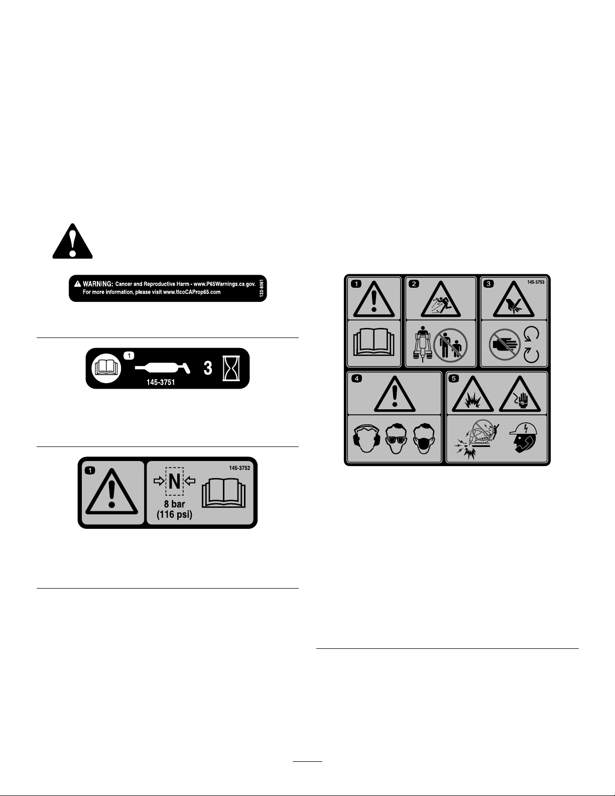
Seguridadde
Pegatinasdeseguridade
mantenimientoy
almacenamiento
•Compruebeaintervalosfrecuentesquelas
jacionesesténcorrectamenteapretadaspara
asegurarsedequeelequipopuedefuncionarde
formasegura.
•ConsulteesteManualdeloperadorparaconocer
detallesimportantessivaaalmacenarelaccesorio
duranteunperiododetiempoprolongado.
•Mantengaosustituyalasetiquetasdeseguridady
deinstrucciones,talycomoseanecesario.
Laspegatinaseinstruccionesdeseguridadestánalavistadeloperadoryestánubicadas
cercadecualquierzonadepeligropotencial.Sustituyalaspegatinasqueesténdañadaso
quefalten.
decal133-8061
133-8061
instrucciones
decal145-3751
145-3751
1.LeaelManualdeloperador;engraselamáquinacada3
horas.
decal145-3752
145-3752
1.Advertencia–Presiónmáxima8bares;leaelManualdel
operador.
1.Advertencia–leael
Manualdeloperador.
2.Peligrodeobjetos
arrojados–mantenga
alejadasaotraspersonas
3.Peligrode
corte/desmembramiento
delamano–permanezca
alejadodelaspiezasen
movimiento.
decal145-3753
145-3753
4.Advertencia–lleve
protecciónauditiva,ocular
yrespiratoria.
5.Peligrodeexplosión
ydescargaeléctrica–
noutilicelamáquina;
póngaseencontacto
conlaempresalocalde
electricidad.
5

Montaje
Elproducto
1
Instalacióndelpuntero
Nosenecesitanpiezas
Procedimiento
ConsulteInstalacióndelpuntero(página9).
Especicaciones
Nota:Lasespecicacionesyeldiseñoestánsujetos
amodicaciónsinprevioaviso.
Anchura63cm
Longitud130cm
Altura33cm
Peso176kg
Longituddetrabajodel
puntero
Diámetrodelpuntero
Clasedeenergíadelimpacto
Velocidaddeimpacto600a1150golpesporminuto
Caudal
Aperosyaccesorios
Estádisponibleunaseleccióndeaperosyaccesorios
homologadosporT oroquesepuedenutilizar
conlamáquinaandepotenciaryaumentar
susprestaciones.Póngaseencontactoconsu
serviciotécnicoautorizadooconsudistribuidor
Toroautorizado,obienvisitewww.T oro.compara
obtenerunalistadetodoslosaperosyaccesorios
homologados.
29cm
5cm
339J
20a35Lporminuto
Paraasegurarunrendimientoóptimoylacontinuada
certicacióndeseguridaddelamáquina,utilice
únicamentepiezasyaccesoriosgenuinosT oro.Las
piezasderepuestoyaccesoriosdeotrosfabricantes
podríanserpeligrosos,ysuusopodríainvalidarla
garantíadelproducto.
6
Operación
Importante:Enlasunidadesdetracciónserie
300,asegúresedeinstalarelkitdeválvulade
alivioenlaunidaddetracciónantesdeusarel
martillohidráulico.Encasodenoinstalarelkit,se
puedenproducirdañosenlaunidaddetracción.
ConsulteasuServicioTécnicoAutorizadopara
obtenermásinformación.
Instalaciónyretiradadel
accesorio
ConsulteenelManualdeloperadordelaunidadde
tracciónelprocedimientodeinstalaciónyderetirada.
Importante:Antesdeinstalarelaccesorio,
coloquelamáquinaenunasupercienivelada,
asegúresedequelasplacasdemontajeestán
libresdesuciedadoresiduosydequelos
pasadoresgiranlibremente.Silospasadoresno
giranlibremente,engráselos.
ADVERTENCIA
Lasfugasdeuidohidráulicobajopresión
puedenpenetrarenlapielycausarlesiones.
Cualquieruidoinyectadobajolapieldebe
sereliminadoquirúrgicamenteenunashoras
porunmédicofamiliarizadoconestetipo
delesión,delocontrariopodríaproducirse
gangrena.
•Asegúresedequetodaslasmanguerasy
líneasdeuidohidráulicoestánenbuenas
condicionesdeuso,yquetodoslos
acoplamientosyconexioneshidráulicos
estánapretados,antesdeaplicarpresión
alsistemahidráulico.
•Mantengaelcuerpoylasmanosalejados
defugaspequeñasoboquillasqueliberan
uidohidráulicoaaltapresión.
•Utiliceuncartónounpapelparabuscar
fugashidráulicas;noutilicenuncalas
manos.
Nota:Utilicesiemprelaunidaddetracciónpara
levantarymoverelaccesorio.
ADVERTENCIA
Siustednoacoplacompletamentelos
pasadoresdeengancherápidoatravésdela
placademontajedelaccesorio,elaccesorio
podríacaersedelamáquina,aplastándolea
ustedoaotrapersona.
Asegúresedequelospasadoresdeenganche
rápidoestáncorrectamenteintroducidosen
laplacademontajedelaccesorio.
CUIDADO
Losacoplamientoshidráulicos,las
mangueras/válvulashidráulicosyeluido
hidráulicopuedenestarcalientes.Si
ustedtocauncomponentecaliente,puede
quemarse.
•Lleveguantesaldesconectarlos
acoplamientoshidráulicos.
•Dejequelamáquinaseenfríeantesde
tocarloscomponenteshidráulicos.
•Notoquelosderramesdeuidohidráulico.
Seleccióndeuna
herramienta
Utilicelasiguientetablaparaelegirlaherramienta
másadecuadaparasuuso:
HerramientaUso
Cincel
Deberáutilizarseentodas
lastareasdemovimiento
detierras,excavacionesen
zanjasestrechas,terreno
estraticadoorocasconhasta
unniveldedurezamedio.
7

PunterocónicoDeberáutilizarseparademoler
Cincelparaasfalto
rocasymateriales,norocas
estraticadas,conhastaun
niveldedurezamedio.
Deberáutilizarseparacortar
pavimentodeasfalto,paredes
deladrillosocésped.
Sustitucióndelpuntero
Retiradadelpuntero
1.Aparquelamáquinaenunasupercienivelada
yaccioneelfrenodeestacionamiento(ensu
caso).
2.Elevelosbrazosdecargaeinclineelmartillo
hidráulico,demodoquequedevertical.
3.Bajeelpunterohastalatierraparapresionarlo
enelmartillohidráulicohastaquesedetenga.
extractordelpasadorpararetirarlos2tapones
delospasadoresdelretenedor.
Nota:Noretirelospasadoresdelretenedor,ya
queelpunteropodríacaerse.
Figura5
1.Extractordelpasadordel
puntero
8.Retirelosbloqueosdelcilindrodelbrazode
carga.
9.Bajelosbrazosdecargaycoloqueelmartillo
hidráulicosobrebloquesdemadera.
2.Tapóndelpasadordel
retenedor(2)
g359829
Figura3
4.Apagueelmotoryretirelallave.
5.Instalelosbloqueosdeloscilindros.
6.Utiliceunmartilloyelextractordelpasador
delpunteropararetirareltapóndeltopeyel
pasadordeltope.
Figura4
10.Apagueelmotoryretirelallave.
11.Utiliceelextractordelpasadordelpuntero
desdelapartededebajodelospasadoresdel
g359140
retenedorpararetirarlospasadores.
g359830
Figura6
12.Retireelpuntero.
g358958
1.Extractordelpasadordel
puntero
2.Pasadordeltope
3.Tapóndeltope
7.Desdeelladoopuestodelostaponesdelos
pasadoresdelretenedor,utiliceunmartilloyel
g359828
Figura7
8

Instalacióndelpuntero
1.Asegúresedequeelmartillohidráulicoseapoya
enelsuelo.
2.Engraseelpunteroyelinteriordelcasquillodel
puntero.
Figura8
g358956
Figura10
1.Pasadordeltope3.Extractordelpasador
2.Tapóndeltope
g358954
1.Casquillodelpuntero
2.Puntero
3.Inserteelpunteroenlacarcasadelmartillo
hidráulico.
4.Instalelos2pasadoresderetención.
Figura9
5.Utiliceunmartilloyelextractordelpasadordel
punteroparainstalarelpasadordeltopeyel
tapóndeltope.
Importante:Asegúresedequeeltapóndel
topeestáinsertadototalmenteenlacarcasa,
talycomosemuestraenlaFigura11.
g358957
Figura11
1.Pasadordeltope2.Tapóndeltope
6.Instalelos2taponesdelpasadordelretenedor.
g358955
g359804
Figura12
1.Tapóndelpasadordelretenedor(2)
9
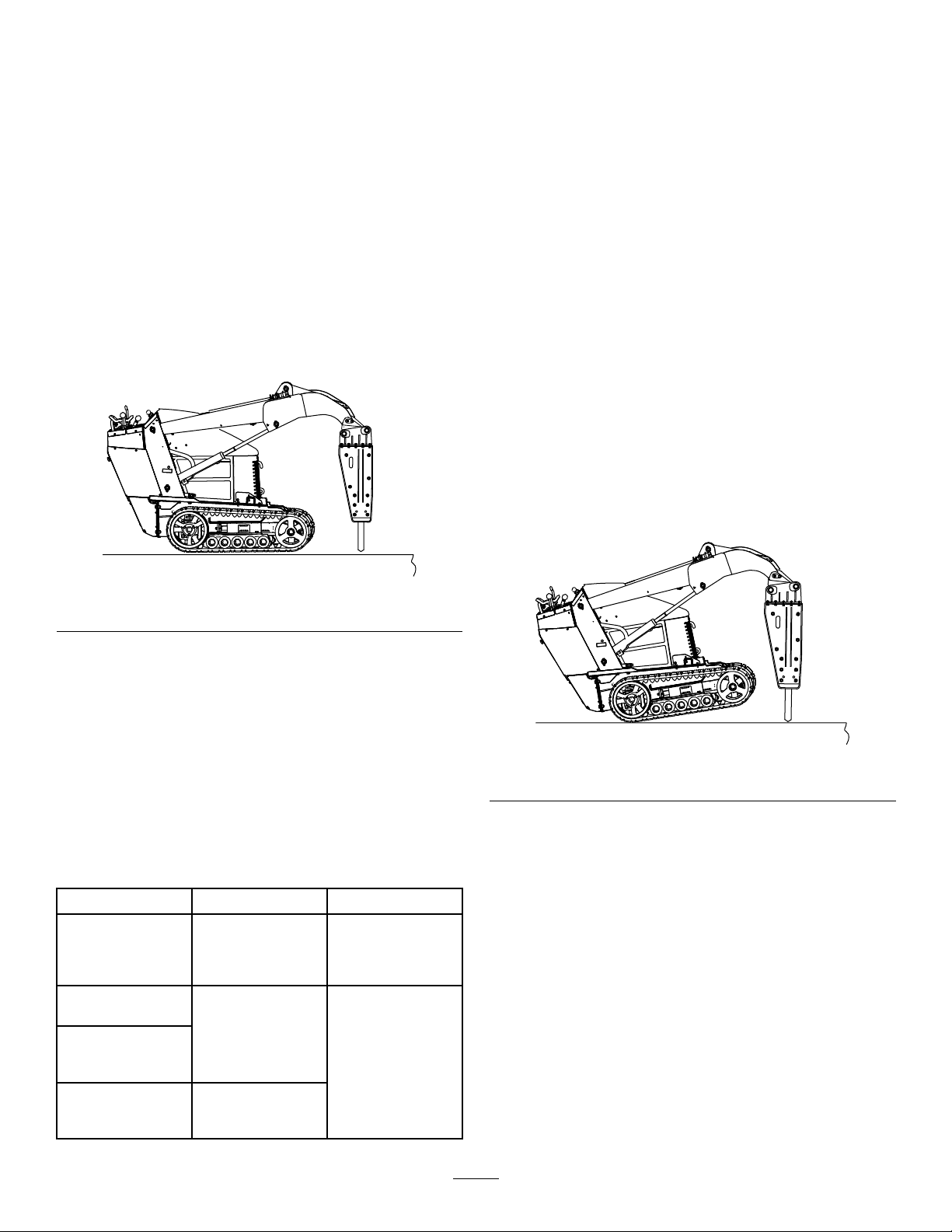
Pruebadelmartillo
Roturademateriales
rompedor
Importante:Trasinstalarelmartillohidráulico
enunamáquina,sobretodotrashaberestado
almacenado,pruébelosiempreantesderomper
cualquiermaterial,paraeliminarelairedelcircuito
deaceite.Siseutilizaelmartillohidráulicode
inmediatosinliberarelaire,serompelapelícula
deaceiteyhacequeelmartillohidráulicosegripe.
1.Aparquelamáquinaenunasupercienivelada
yaccioneelfrenodeestacionamiento(ensu
caso).
2.Elevelosbrazosdecargaeinclineelmartillo
hidráulico,demodoquequedevertical.
Asegúresedequeelpunteronotocalatierra.
Importante:Alimpactarenlamismaubicación
continuamentedurantelargosperiodosde
tiempo,segeneranaltastemperaturasenlapunta
delpuntero.Elpunteropodríaalcanzartambién
temperaturaselevadasalimpactaravelocidades
demasiadoaltasobajas,perderíaecaciayloy
sedestrozaría.
1.Ajustelaaceleracióndelamáquinacuantosea
necesariopararomperelmaterial:
•Paramáquinasdelaserie300,utilicela
aceleraciónmáxima(máximavelocidad
delmotor),utiliceunrangobajo(posición
detortuga)enlapalancadeselecciónde
velocidadyajustelaválvuladeldivisorde
ujoaaproximadamentelaposicióndelas
10enpunto.
•Enelcasodemáquinase-Dingo,cambieel
mododeaccesorioamododemartillo.
•EnmáquinasdelaserieTX,utilice3/4de
aceleración.
2.Coloqueelpunterodelmartillohidráulicoaentre
15y46cmdelbordedelmaterialquesequiera
romper,enunángulode90grados.
Figura13
3.Accionelentamenteelsistemahidráulico
delanterohastaqueelpistóndelmartillo
hidráulicoseelevey,acontinuación,démarcha
atráslentamenteenelsistemahidráulicoantes
dequeelpistónimpacte.
Importante:Nodejequeelpistónimpacte.
4.Consultelatablaparaconocerlostiemposde
pruebaparalas2etapas.
Importante:Nodejequeelpistónimpacte
durantelaretiradadeaireyeltiempode
recuperacióndelajunta.
12
Retiradadeaire
Nuevomartillo
rompedor
Traslaconexión
demangueras,sin
reparaciones
Trasrealizar
reparacionesenel
martillohidráulico
ytiempode
recuperaciónde
lajunta
15minutos
20minutos
Tiempode
preparación
Accionela
máquinadurante
10minutoscon
unaaceleración
del50%y ,
acontinuación,
20minutoscon
unaaceleración
del70%.
g359139
g359138
Figura14
3.Apliquepresiónhaciaabajoconlosbrazosde
cargahastaquelapartedelanteradelaunidad
detracciónseelevedelatierraunos5cm.
Nota:Noaccioneelmartillohidráulico,a
menosqueelpunteroestésobrelatierrayse
apliquepresiónhaciaabajo.
Importante:Asegúresedequeloscilindros
hidráulicostengaunrecorridodealmenos
5cm;noutiliceelmartillohidráulicoconlos
cilindroshidráulicostotalmenteextendidos.
4.Accioneelmartillohidráulicoymantengala
presiónhaciaabajoamedidaqueelpuntero
atraviesaelmaterialqueseestárompiendo.
5.Cuandoelmaterialestéroto,desengranede
inmediatoelsistemahidráulicoparadejarde
golpearelmaterial.
10

Roturadeunasupercie
vertical
1.Coloqueelpunterosobrelasupercievertical
delmismomodoquelocolocaríasobreuna
superciehorizontal.
2.Mantengalapresiónenelpunteroconduciendo
launidaddetracciónhaciadelante,haciala
supercievertical,mientrasaccionaelmartillo
hidráulico.
3.Bajeperiódicamenteelmartillohidráulicoa
unaposiciónverticalparadejarquecaiganlos
residuosquesehayanacumuladoenelmartillo
hidráulico.
Posicióndetransporte
Altransportarelaccesorio,manténgalolomáscerca
posibledelsuelo,nomásde15cmporencimadel
suelo.Inclínelohaciaatrás.
sereducelapresiónhaciaabajo.Silapresión
haciaabajodesdelaunidadesdemasiadodébil,
escucharágolpesmetálicosdelmartillocuando
golpeeelpunterodeformaincorrecta.
•Unapresiónexcesivahaciaabajoproducefuertes
vibracionesenlaunidad.
•Muchosmaterialesnoserompenbiencuando
seusaelmartillocontinuamenteenunlugar.
Cadavezqueelmartillopenetreelmaterialsin
romperlo,despláceloaunanuevaubicación
enlíneaparalelaconelextremodelmaterial,a
unos7,6cmdeloricioanterior.Estovacreando
muescasenelmaterialy,alrealizarseenrepetidas
ocasiones,rompeunagranpartedelmaterial.
Figura15
1.Nomásde15cmpor
encimadelsuelo
2.Inclinarelaccesoriohacia
atrás.
Consejosdeoperación
•Sielpunterosecolocademasiadolejosdelborde
delmaterial,elmaterialpuedeabsorberlaenergía
ynoromperse.
•Sielmaterialnoserompetras1minuto,detenga
elmartillohidráulicoymuevaelpunteroauna
ubicacióndistinta.
•Nounaelpunteroenelmaterialqueseestá
cortando,yaquepodríadoblarseodesgastarse
deformaprematura.Asegúresedequetoda
lafuerzaqueseaplicaenelmartillohidráulico
estáalineadaconelpuntero,nodeladoaladoni
delapartedelanteraalatrasera.Estorequiere
ajustesfrecuentesenlacolocacióndelaunidad
detracción.
•Escucheelsonidodelmartillohidráulicocuando
estáenfuncionamiento.Elsonidocambiacuando
g359750
Figura16
g359749
•Siestárompiendohormigónarmado,utiliceun
punterodecincelenelmartillohidráulicopara
cortarlasbarrasenelhormigón.T ambiénpuede
cortarlasbarrasconunsoplete.
•Paraaumentarlavidaútildelmartillo
hidráulico:
–Asegúresedequeloscilindroshidráulicos
tengaunrecorridodealmenos5<cm;no
utiliceelmartillohidráulicoconloscilindros
hidráulicostotalmenteextendidos.
–Nohaganuncapalancaconelpunterodel
martillohidráulico.
–Evitegolpeardeformaabruptaelmaterialcon
elpuntero.
–Noutiliceelmartillohidráulicoparaelevaro
desplazarmaterial.
–Noutiliceelmartillohidráulicobajoelagua,
solodejequeseintroduzcaelpunteroenel
agua.
11

Mantenimiento
CUIDADO
Sidejalallaveenelinterruptordeencendido,alguienpodríaarrancarelmotoraccidentalmente
ycausarlesionesgravesaustedoaotraspersonas.
Retirelallavedecontactoantesderealizarcualquieroperacióndemantenimiento.
Calendariorecomendadodemantenimiento
Intervalodemanteni-
mientoyservicio
Cadavezqueseutilice
odiariamente
Cada40horas
Cada100horas
Antesdelalmacenamiento
Procedimientodemantenimiento
•Engraseelpuntero.Engráselocada3horasdefuncionamientoydespuésde
cadalavado.
•Compruebequelaslíneashidráulicasnotienenfugasoconexionessueltas,queno
estántorcidas,quelossoportesnoestánsueltos,yquenohaydesgasteodeterioro
causadoporagentesambientalesoquímicos.
•Inspeccioneyaprietetodaslasjaciones.
•Inspeccionelospasadoresdemontaje,lostaladros,elcojinetedelpunteroylos
pasadoresdelretenedorparacomprobarsiestánsueltosodesgastados.Vuelvaa
colocarlosoaasentarlos,segúnseanecesario.
•Midalalongituddelpunterocuandosepresioneenelsoporte.Sustituyaelpuntero
silalongitudmedidaesinferiora200mm.
•Compruebelacargadenitrógenoenelacumulador.
•Pintecualquiersuperciedesconchada.
Engrasadodelpuntero
Intervalodemantenimiento:Cadavezqueseutilice
odiariamenteEngráselocada3
horasdefuncionamientoydespués
decadalavado.
Tipodegrasa:Grasadepropósitogeneral
1.Aparquelamáquinaenunasupercienivelada
yaccioneelfrenodeestacionamiento(ensu
caso).
2.Inclineelmartillohidráulicodeformaquequede
enposiciónverticalybájeloalatierrapara
empujarelpunteroenelmartillohidráulicohasta
quesedetenga.
Importante:Sinoempujaelpunteroen
elmartillohidráulicoantesdeengrasarlo,
puedellenarsedegrasaelespacioentre
lapartesuperiordelpunteroyelpistón
delmartillohidráulico.Estohacequeel
pistónpresionelagrasaysedañelajuntala
próximavezqueuseelmartillohidráulico.
3.Apagueelmotoryretirelallave.
4.Limpieelengrasadorconuntrapo.
5.Conecteunapistoladeengrasaralengrasador.
g359783
Figura17
6.Bombeegrasaenelengrasadorhastaque
comienceasalirporelcojineteinferioryel
pasadorderetención,obienhastaqueresulte
difícilbombearlagrasa.
7.Limpiecualquierexcesodegrasa.
12

Comprobacióndelacarga
denitrógeno
Intervalodemantenimiento:Cada100
horas—Compruebelacarga
denitrógenoenelacumulador.
ADVERTENCIA
Dentrodelmartillohidráulicohayunacámara
quecontienenitrógenoapresión,quepodría
explotarsisedanlascircunstanciaspropicias
yproducirlesionesolamuertealoperadoro
aotraspersonas.
•Nodesmonteelcuerpodelmartillo
hidráulico.
•Nointentecargarlacámaraporsímismo.
Llevesiempreelmartillohidráulicoaun
ServicioTécnicoAutorizadoparaque
realicenlacarga.
•Asegúresedequeelmartillohidráulico
solosecargaconnitrógeno.Otrosgases
puedenexplotar.
•Notransporteelmartillohidráulico
cargadoporvíaaérea.
Dentrodelmartillohidráulicohayunacumulador,una
cámaraparaelnitrógenoapresión.Trasvariashoras
deuso,lapresiónpuededescender,conloquese
reduceelrendimientodelmartillohidráulico.
Unasvibracionesfuertesenlasmangueras
hidráulicasauxiliaressonunindiciodequelapresión
estádescendiendoenlacámara.Siocurrieraesto,
lleveelmartillohidráulicoaunServicioTécnico
Autorizadoparaquelocarguen.
Presióndelgasdenitrógeno:8bar
1.Aparquelamáquinaenunasupercienivelada,
accioneelfrenodeestacionamiento(siprocede)
ybajeelmartillohidráulicoalsuelo.
2.Apagueelmotoryretirelallave.
3.Retireeltapóndelaválvuladegasdelatapa
delcilindro.
g359809
Figura18
1.Válvuladegas3.Tapóndelaválvuladegas
2.Manómetro
4.Inserteunmanómetroenlaválvuladegasy
midalapresión.
5.Siesbaja,póngaseencontactoconsuServicio
TécnicoAutorizadoparacargarlo.
Comprobacióndelas
manguerashidráulicas
Intervalodemantenimiento:Cadavezqueseutilice
odiariamente
ADVERTENCIA
Lasfugasdeuidohidráulicobajopresión
puedenpenetrarenlapielycausarlesiones.
Cualquieruidoinyectadobajolapieldebe
sereliminadoquirúrgicamenteenunashoras
porunmédicofamiliarizadoconestetipo
delesión,delocontrariopodríaproducirse
gangrena.
•Mantengaelcuerpoylasmanosalejados
defugaspequeñasoboquillasqueliberan
uidohidráulicoaaltapresión.
•Utiliceuncartónounpapelparabuscar
fugashidráulicas;noutilicenuncalas
manos.
13

Almacenamiento
Almacenamientodel
accesorio
1.Aparquelamáquinaenunasupercienivelada
yaccioneelfrenodeestacionamiento(ensu
caso).
2.Coloqueelmartillohidráulicosobre2trozosde
madera,demodoqueelladodelcilindroesté
másaltoqueelladodelsoportedelcincel.
g359806
Figura20
1.Tapóndecabezahexagonal
8.Sielaccesoriosevaaalmacenardurante
másde30días,liberelapresióndelgasdel
accesorio.
A.Retireelpuntero;consulteRetiradadel
puntero(página8).
B.Libereelgasdenitrógenodesdelacubierta
delcilindro,atravésdelaválvuladegas.
Figura19
3.Retireelaccesoriodelamáquina.
4.Laveelaccesoriocondetergentesuaveyagua
paraeliminarcualquiersuciedad.
5.Reviseyaprietetodoslospernos,tuercasy
tornillos.Repareocambiecualquierpieza
dañadaodesgastada.
6.Pintelassuperciesqueesténarañadaso
dondeestévisibleelmetal.Puedeadquirirla
pinturaensuServicioTécnicoAutorizado.
7.Retireeltapóndecabezahexagonalyrocíecon
unaerosolantioxidanteeneláreadelpistón.
Coloqueeltapóndecabezahexagonal.
g359808
g359805
Figura21
1.Válvuladegas
C.Coloqueunrecipientedebajodelas
manguerasyaojelostapones.
1.Tapóndemanguera2.Varilla
D.Inserteunavarillaenelpistónyempújela
ligeramenteconunmartillo.
14
g359807
Figura22

Nota:Asíseliberacualquierexcesode
gasdenitrógenodelacámaraamortiguada.
E.Aprietelostaponesdelasmangueras.
F.Engraseelpunteroeinstálelo;consulte
Instalacióndelpuntero(página9).
9.Almaceneelmartillohidráulicoenungarajeo
almacénlimpioyseco.Cúbraloparaprotegerlo
yparaconservarlolimpio.
10.Alretirarelmartillohidráulicodellugarde
almacenamiento,sustituyaelgasdenitrógeno
antesdeusarlo;póngaseencontactoconsu
ServicioTécnicoAutorizado.
15

Solucióndeproblemas
ProblemaPosiblecausa
Hayfugasdeuidohidráulico.
Seproducenfugasdemásde10bares
degasdenitrógenocada100horas.
Elmartillohidráuliconoimpacta.
Elmartillohidráulicoimpactadeforma
errática.
Accióncorrectora
1.Unajuntadeaceite,unajuntatórica
ounanilloderespaldopresenta
desgasteodaños.
2.Elpistónoelcilindrosehangripado.
3.Latuercadelabiela,eltapón
delestárteroeladaptadordelas
manguerassehasoltado.
1.Unajuntatórica,unpistónounajunta
presentadesgasteodaños.
2.Elpistónoelcilindrosehangripado.
1.Latemperaturadeluidohidráulicoes
demasiadobaja.
2.Lapresióndelgasdenitrógenoenla
cámaraesdemasiadoalta.
3.Laválvuladeparadaestácerrada.3.Abralaválvuladeparada.
4.Elajustedelapresióndelaválvulade
alivioesdemasiadobajo.
5.Elrendimientodelabombahidráulica
esdeciente.
1.Laválvuladecontrol,elpistónoel
cilindrosehangripado.
2.Elajustedelapresióndelaválvulade
alivioesdemasiadobajo.
3.Elrendimientodelabombahidráulica
esdeciente.
4.Nohaysucientepresiónhaciaabajo
enelpuntero.
5.Lapresióndelgasdenitrógenoenla
cámaraesdemasiadoalta.
1.PóngaseencontactoconsuServicio
TécnicoAutorizado.
2.PóngaseencontactoconsuServicio
TécnicoAutorizado.
3.Aprietelapiezasuelta.
1.PóngaseencontactoconsuServicio
TécnicoAutorizado.
2.PóngaseencontactoconsuServicio
TécnicoAutorizado.
1.Calienteelmartillohidráulico.
2.Liberelapresióndelgashastaelnivel
correcto.
4.PóngaseencontactoconsuServicio
TécnicoAutorizado.
5.PóngaseencontactoconsuServicio
TécnicoAutorizado.
1.PóngaseencontactoconsuServicio
TécnicoAutorizado.
2.PóngaseencontactoconsuServicio
TécnicoAutorizado.
3.PóngaseencontactoconsuServicio
TécnicoAutorizado.
4.Apliquemáspresiónhaciaabajoenel
puntero.
5.Liberelapresióndelgashastaelnivel
correcto.
Elmartillohidráuliconotienesuciente
potencia.
Elmartillohidráuliconoimpacta.
1.Lapresióndelgasdenitrógenoenla
cámaraesdemasiadobaja.
1.Lapresióndelgasdenitrógenoenla
cámaraesdemasiadoalta.
2.Nohaysucientepresiónhaciaabajo
enelpuntero.
3.Elajustedelapresióndelaválvulade
alivioesdemasiadobajo.
4.Elrendimientodelabombahidráulica
esdeciente.
Hayunaobstrucciónenunadelas
5.
manguerashidráulicas.
1.PóngaseencontactoconsuServicio
TécnicoAutorizado.
1.Liberelapresióndelgashastaelnivel
correcto.
2.Apliquemáspresiónhaciaabajoenel
puntero.
3.PóngaseencontactoconsuServicio
TécnicoAutorizado.
4.PóngaseencontactoconsuServicio
TécnicoAutorizado.
Eliminelaobstrucciónosustituyala
5.
manguera.
16

Notas:

DeclaracióndeIncorporación
TheToroCompany,81 11LyndaleAve.South,Bloomington,MN,EE.UU.,declaraqueel/losequipo(s)
siguiente(s)cumple(n)lasdirectivascitadas,siseinstalanconarregloalasinstruccionesadjuntasen
determinadosmodelosTorosegúnloindicadoenlasDeclaracionesdeconformidadpertinentes.
Nºde
modelo
23136321000001ysuperiores
Nºdeserie
Descripcióndel
Martillohidráulico,
minicargadorascompactas
producto
Descripcióndela
factura
HYDRAULICBREAKER,
DINGO
Descripcióngeneral
Minicargadoracompacta
Directiva
2006/42/CE
SehacompiladoladocumentacióntécnicapertinenteexigidaporlaParteBdelAnexoVIIde2006/42/CE.
Noscomprometemosatransmitir,apeticióndelasautoridadesnacionales,informaciónpertinentesobreesta
maquinariaparcialmentecompleta.Elmétododetransmisiónseráelectrónico.
EstamaquinarianodebeponerseenserviciohastaquehayasidoincorporadaenlosmodelosToro
homologados,segúnloindicadoenlaDeclaracióndeconformidadcorrespondienteydeacuerdocontodaslas
instrucciones,paraquepuedadeclararseconformeatodaslasDirectivaspertinentes.
Certicado:
MichaelBenedict
DirectordeIngeniería
811 1LyndaleAve.South
Bloomington,MN55420,USA
Julio13,2021
Representanteautorizado:
MarcelDutrieux
ManagerEuropeanProductIntegrity
ToroEuropeNV
Nijverheidsstraat5
2260Oevel
Belgium

Avisodeprivacidad–EEE/RU
UsodesuinformaciónpersonalporT oro
TheT oroCompany("T oro")respetasuprivacidad.Cuandocompranuestrosproductos,podemosrecopilarciertainformaciónpersonalsobreusted,bien
directamente,bienatravésdesuconcesionariooempresaT orolocal.T oroutilizaestainformaciónparasatisfacersusobligacionescontractuales,por
ejemplopararegistrarsugarantía,procesarsureclamaciónbajolagarantíaoponerseencontactoconustedsiseproducelaretiradadeunproducto–y
parapropósitoscomercialeslegítimos,comoporejemploevaluarlasatisfaccióndelosclientes,mejorarnuestrosproductosuofrecerleinformaciónsobre
productosquepuedenserdesuinterés.Toropuedecompartirsuinformaciónconnuestrasliales,aliados,concesionariosuotrossocioscomerciales
respectoacualquieradeestasactividades.Tambiénpodemosdivulgarinformaciónpersonalcuandoloexijalaleyoenrelaciónconlaventa,lacomprao
lafusióndeunaempresa.Nuncavenderemossuinformaciónpersonalaningunaotraempresaconnesdemarketing.
Retencióndesuinformaciónpersonal
Toromantendrásuinformaciónpersonalduranteeltiempoenqueseapertinenteparalosnesanterioresyconarregloaloestipuladoenlalegislación
vigente.Sideseaobtenermásinformaciónsobrelosperiodosderetenciónaplicables,porfavorpóngaseencontactoconlegal@toro.com.
CompromisodeToroconlaseguridad
SusdatospersonalespuedenserprocesadosenEstadosUnidosoenotropaísqueapliqueleyesdeproteccióndedatosmenosestrictasquelasdesu
paísderesidencia.Sitransferimossuinformaciónfueradesupaísderesidencia,tomaremoslasmedidaslegalmenteestipuladasparaasegurarque
existanmedidasdeseguridadadecuadasparaprotegersuinformaciónyparagarantizarquesetratedeformasegura.
Accesoyrecticación
Ustedpuedetenerderechoacorregirorevisarsusdatospersonales,oaoponerseaorestringirelprocesamientodesusdatos.Parahacerlo,póngase
encontactoconnosotrosporcorreoelectrónicoalegal@toro.com.SitienepreguntassobrelaformaenqueTorohamanejadosuinformación,
sugerimosquesepongaencontactoconnosotrosdirectamente.Recuerdequelosresidenteseuropeostienenderechoapresentarquejasantela
autoridadresponsabledelaproteccióndedatos.
374-0282RevC

InformaciónsobreadvertenciasdelaPropuesta65deCalifornia
¿Enquéconsisteestaadvertencia?
Esposiblequeveaunproductoalaventaconunaetiquetadeadvertenciacomolasiguiente:
ADVERTENCIA:Cáncerydañosreproductivos–www.p65Warnings.ca.gov.
¿QuéeslaPropuesta65?
LaPropuesta65seaplicaacualquierempresaqueopereenCalifornia,quevendaproductosenCaliforniaoquefabriqueproductosquepuedan
venderseollevarseaCalifornia.EstipulaqueelgobernadordeCaliforniadebemantenerypublicarunalistadesustanciasquímicasconocidaspor
causarcáncer,defectoscongénitosy/odañosreproductivos.Lalista,queseactualizamanualmente,incluyecientosdesustanciasquímicasquese
encuentranennumerososartículoscotidianos.LanalidaddelaPropuesta65esinformaralpúblicosobrelaexposiciónaestassustanciasquímicas.
LaPropuesta65noprohíbelaventadeproductosquecontienenestassustancias,perorequierelainclusióndeadvertenciasencualquierproducto,
embalajeodocumentaciónconelproducto.Porotrolado,laadvertenciadelaPropuesta65nosignicaqueunproductoinfrinjalosrequisitoso
estándaresdeseguridaddelosproductos.Dehecho,elGobiernodeCaliforniahaaclaradoqueunaadvertenciadelaPropuesta65“noequivaleauna
decisiónnormativadequeunproductosea‘seguro’o‘noseguro’”.Muchasdeestassustanciassehanutilizadoenproductosdeusodiarioduranteaños
sindocumentarningúndaño.Paraobtenermásinformación,visitehttps://oag.ca.gov/prop65/faqs-view-all
UnaadvertenciadelaPropuesta65signicaqueunaempresa(1)haevaluadolaexposiciónyhaconcluidoquesupera“elnivelderiesgono
signicativo”,obien(2)haoptadoporproporcionarunaadvertenciabasándoseensucomprensiónsobrelapresenciadeunasustanciaquímica
incluidaenlalistasinintentarevaluarlaexposición.
¿Estaleyseaplicaatodosloslugares?
LasadvertenciasdelaPropuesta65solosonobligatoriasenvirtuddelaleydeCalifornia.EstasadvertenciassevenportodaCaliforniaenunavariedad
deentornos,incluidosatítuloenunciativoynolimitativo,restaurantes,establecimientosdealimentación,hoteles,centroseducativosyhospitales,así
comoenunaampliavariedaddeproductos.Porotrolado,algunosminoristasdeventaonlineyporcorreoincluyenadvertenciasdelaPropuesta
65ensussitioswebyensuscatálogos.
.
¿EnquésediferencianlasadvertenciasyloslímitesfederalesenCalifornia?
LasnormasdelaPropuesta65confrecuenciasonmásestrictasquelasnormasfederaleseinternacionales.Existendistintassustanciasquerequieren
unaadvertenciadelaPropuesta65anivelesmuchomásbajosqueloslímitesfederales.Porejemplo,lanormadelaPropuesta65deadvertencias
relativasalplomoesde0,5μg/día,queesunvalormuypordebajodelasnormasfederaleseinternacionales.
¿Porquénollevanlaadvertenciatodoslosproductossimilares?
•LosproductosvendidosenCaliforniadebenllevareletiquetadodelaPropuesta65,mientrasqueotrosproductossimilaresquesevenden
enotroslugaresnotienenquellevarlos.
•EsposiblequeaunaempresaimplicadaenunlitigiosobrelaPropuesta65quellegueaunacuerdoseleobligueautilizaradvertenciasdela
Propuesta65ensusproductos,mientrasqueotrasempresasquefabriquenproductossimilarespuedequenotenganquecumpliresterequisito.
•LaaplicacióndelaPropuesta65noescoherente.
•LasempresaspuedenoptarpornoofreceradvertenciasporqueconcluyanquenotienenquehacerloenvirtuddelaPropuesta65;lafaltade
advertenciasparaunproductonosignicaqueelproductonocontengasustanciasquímicasincluidasenlalistaennivelessimilares.
¿PorquéToroincluyeestaadvertencia?
Torohaoptadoporofreceralosconsumidoreselmáximodeinformaciónposibleparaquepuedantomardecisionesinformadassobrelosproductosque
compranyusan.T oroofreceadvertenciasenciertoscasossegúnsuconocimientodelapresenciadeunaomássustanciasquímicasenlalista,sin
evaluarelniveldeexposición,yaquenotodaslassustanciasquímicasdelalistaincluyenrequisitosdelímitedeexposición.Sibienlaexposicióndelos
productosdeT oropuedeserinsignicanteodentrodelrangode“riesgonosignicativo”,paramayorcautelaT orohaoptadoporincluirlasadvertencias
delaPropuesta65.Además,siT oronoincluyeestasadvertencias,podríaenfrentarseademandasinterpuestasporelEstadodeCaliforniaobienpartes
privadasquedeseenaplicarlaPropuesta65ylaempresapodríaenfrentarseaimportantessanciones.
RevA
FormNo.3447-318RevA
Brise-béton
Porte-outilscompacts
N°demodèle23136—N°desérie321000001etsuivants
Enregistrezvotreproduitàwww.Toro.com.
Traductiondutexted'origine(FR)
*3447-318*
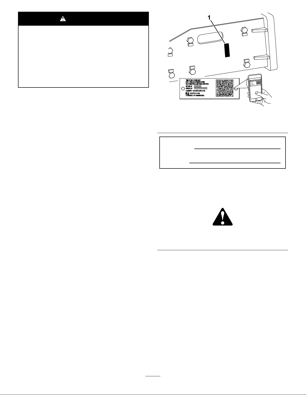
ATTENTION
CALIFORNIE
Proposition65-Avertissement
L'utilisationdeceproduitpeutentraîner
uneexpositionàdessubstances
chimiquesconsidéréespasl'étatde
Californiecommecapablesdeprovoquer
descancers,desanomaliescongénitales
oud'autrestroublesdelareproduction.
Introduction
Cebrise-bétonestprévupourêtreutilisésurun
porte-outilcompactToro.Ilestprincipalementconçu
pourbriserlebéton,l'asphalte,larocheoudela
briquedurantdestravauxderénovation.
g360512
Figure1
1.Emplacementdesnumérosdemodèleetdesérie
N°demodèle
Lisezattentivementcettenoticepourapprendre
commentutiliseretentretenircorrectementvotre
produit,etéviterainsidel'endommageroudevous
blesser.Vousêtesresponsabledel'utilisationsûreet
correcteduproduit.
Rendez-voussurwww.Toro.compourtoutdocument
deformationàlasécuritéetàl'utilisationdes
produits,pourtoutrenseignementconcernantun
produitouunaccessoire,pourobtenirl'adressedes
concessionnairesoupourenregistrervotreproduit.
Pourobtenirdesprestationsdeservice,despièces
d'origineoudesrenseignementscomplémentaires,
munissez-vousdesnumérosdemodèleetdesériedu
produitetcontactezunconcessionnaire-réparateur
agrééouleserviceclientdufabricant.Lesnuméros
demodèleetdesériesontimpriméssuruneplaque
xéeaucôtédroitdelatêted'entraînement.Inscrivez
lesnumérosdansl'espaceréservéàceteffet.
Important:Avecvotreappareilmobile,vous
pouvezscannerlecodeQRsurl'autocollantdu
numérodesérie(lecaséchéant)and'accéder
auxinformationssurlagarantie,lespièces
détachéesetautresrenseignementssurle
produit.
N°desérie
Lesmisesengardedecemanuelsoulignentdes
dangerspotentielsetsontsignaléesparlesymbole
desécurité(Figure2),quiindiqueundangerpouvant
entraînerdesblessuresgravesoumortellessiles
précautionsrecommandéesnesontpasrespectées.
g000502
Figure2
1.Symboledesécurité
Cemanuelutilisedeuxtermespourfairepasser
desrenseignementsessentiels.Important,pour
attirerl'attentionsurdesrenseignementsmécaniques
spéciquesetRemarque,pourinsistersurdes
renseignementsd'ordregénéralméritantuneattention
particulière.
©2021—TheToro®Company
8111LyndaleAvenueSouth
Bloomington,MN55420
Contactez-noussurwww.Toro.com.
2
ImpriméauxÉtats-Unis
Tousdroitsréservés

Tabledesmatières
Sécurité
Sécurité....................................................................3
Consignesdesécuritégénérales........................3
Consignesdesécuritépourl'utilisationsur
despentes......................................................4
Consignesdesécuritéconcernantle
brise-béton......................................................4
Consignesdesécuritépourl'entretienetle
remisage.........................................................5
Autocollantsdesécuritéetd'instruction..............5
Miseenservice.........................................................6
1Installationdel'outil..........................................6
Vued'ensembleduproduit........................................6
Caractéristiquestechniques..............................6
Outilsetaccessoires...........................................6
Utilisation..................................................................7
Poseetdéposedel'accessoire...........................7
Choixd'unoutil...................................................7
Remplacementdel'outil.....................................8
Essayerlebrise-béton......................................10
Briserdesmatériaux.........................................10
Briserunesurfaceverticale...............................11
Positiondetransport..........................................11
Conseilsd'utilisation.........................................11
Entretien.................................................................12
Programmed'entretienrecommandé..................12
Graissagedel'outil...........................................12
Contrôledelacharged'azote...........................13
Contrôledesconduiteshydrauliques................13
Remisage...............................................................14
Remisagedel'accessoire.................................14
Dépistagedesdéfauts............................................15
DANGER
Desconduitespeuventêtreenfouiesdansla
zonedetravail.Vouspouvezprovoquerune
explosionouvousélectrocutersivousles
touchezencreusant.
Marquezaupréalablel'emplacementdes
lignesouconduitesenfouiesdanslazone
detravail,etnecreusezpasàcesendroits.
Contactezleservicedemarquageoula
compagniedeservicepubliclocal(e)pour
fairemarquerleterrain(parexemple,appelez
leservicedemarquagenationalau811pour
États-Unisouau1100pourl'Australie).
Consignesdesécurité
générales
Respecteztoujourstouteslesconsignesdesécurité
pouréviterdesblessuresgravesoumortelles.
•Netransportezpasd'outilaveclesbraslevés.
Transporteztoujoursl'outilprèsdusol;voir
Positiondetransport(page11).
•Marquezaupréalablel'emplacementdeslignes,
conduitesouautresobjetsenfouisdanslazone
detravail,etnecreusezpasàcesendroits.
•Vousdevezlireetcomprendrelecontenude
ceManueldel'utilisateuravantdedémarrerle
moteur.
•Accordeztoutevotreattentionàl'utilisationdela
machine.Nefaitesriend’autrequipuissevous
distraire,aurisquedecauserdesdommages
corporelsoumatériels.
•Neconezjamaisl'utilisationdelamachineàdes
enfantsouàdespersonnesnonqualiées.
•N'approchezjamaislesmainsoulespiedsdes
composantsetaccessoiresmobiles.
•N'utilisezpaslamachines'ilmanquedescapots
oud'autresdispositifsdeprotection,ous'ilssont
endommagés.
•Teneztoutlemonde,ycomprislesanimaux
domestiques,àl'écartdelamachine.
•Arrêtezlamachine,coupezlemoteuretenlevez
lacléavantd'effectuerunentretien,defairele
pleindecarburantoud'élimineruneobstruction
surlamachine.
L'usageoul'entretienincorrectdecettemachinepeut
occasionnerdesaccidents.Pourréduirelesrisques
d'accidentsetdeblessures,respectezlesconsignes
desécuritéquisuivent.T eneztoujourscomptedes
misesengardesignaléesparlesymboledesécurité
3

()etlamentionPrudence,AttentionouDanger.Le
nonrespectdecesinstructionspeutentraînerdes
blessuresgravesoumortelles.
•Utilisezlamachineavecprudenceprèsde:
–Fortesdénivellations
–Fossés
Consignesdesécuritépour
l'utilisationsurdespentes
•Travailleztoujoursdanslesensdelapente
(enmontantouendescendant),lecôtéle
pluslourddelamachineétantenamont.La
répartitiondupoidsvarieselonlesaccessoires
montés.Cetaccessoirealourditl'avantdela
machine.
•Gardezl'accessoireabaissésurlespentes.La
stabilitédelamachineestcompromisesivous
levezl'accessoirealorsvousvoustrouvezsurune
pente.
•Lespentesaugmententsignicativementles
risquesdepertedecontrôleetdebasculement
delamachinepouvantentraînerdesaccidents
graves,voiremortels.L'utilisationdelamachine
surunepente,quellequ'ellesoit,ousurunterrain
accidenté,demandeuneattentionparticulière.
•Établissezvospropresprocéduresetrèglesde
travailàappliquersurlespentes.Cesprocédures
doiventinclureunrepérageetuneétudedu
sitepourdéterminerquellespentespermettent
uneutilisationsécuritairedelamachine.Faites
toujourspreuvedebonsensetdediscernement
quandvousréalisezcetteétude.
•Ralentissezetredoublezdeprudencesurles
pentes.Lanatureduterrainpeutaffecterla
stabilitédelamachine.
•Évitezdedémarreroudevousarrêterencôte.
Silamachineperddesamotricité,descendez
lentementlapenteenlignedroite.
•Évitezdefairedemi-toursurlespentes.Sivousne
pouvezpasfaireautrement,procédezlentement
engardantlecôtélepluslourddelamachineen
amont.
•Déplacez-vousàvitesseréduiteet
progressivementsurlespentes.Nechangezpas
soudainementdevitesseoudedirection.
•Netravaillezpassurlespentessurlesquelles
vousnevoussentezpasàl'aise.
•Méez-vousdestrous,ornièresetbosses,carles
irrégularitésduterrainrisquentdeprovoquerle
retournementdelamachine.L'herbehautepeut
masquerlesaccidentsduterrain.
•Utilisezlamachineavecprudencesurlessurfaces
humides.Eneffet,lapertedemotricitépeutfaire
déraperlamachine.
•Examinezlazoned'utilisationpourvousassurer
quelesolestsufsammentstablepoursupporter
lepoidsdelamachine.
–Berges
–Étenduesd'eau
Lamachinepeutseretournerbrusquementsi
unechenillepassepar-dessusunedénivellation
quelconqueetseretrouvedanslevide,ousi
unbords'effondre.Maintenezunedistancede
sécuritéentrelamachineettoutdangerpotentiel.
•N'enlevezpasounexezpasd'accessoires
lorsquelamachinesetrouvesurunepente.
•Negarezpaslamachinesurunepente.
Consignesdesécurité
concernantlebrise-béton
•Utilisezunéquipementdeprotectionindividuelle
(EPI)etportezdesvêtementsdetravail
appropriés,ycompris:
–Casque
–Respirateuroumasqueantipoussière
–Lunettesdesécurité
–Protecteursd'oreilles
–Chaussuresrobustesàsemelleantidérapante
–Pantalon
–Chemiseàmancheslongues,serréesaux
poignets
–Gantsbienajustés,sanscordondeserrage
nilargesmanchettes
•Aveclesgroupesdedéplacementsurroues,
utilisezlecontrepoidsquandl'accessoireest
monté.
•Maintenezlegroupededéplacementàdistance
dubordquevousbrisez.
•Nebrisezpaslematériaujustesousl'avantdu
groupededéplacement.
•Lebrise-bétoncomprendunechambreremplie
d'azotesouspression,quipeutexplosersiles
circonstancess'yprêtent.Nedémontezpasle
corpsdubrise-béton.
•N'essayezpasdechargerlachambrede
pressionparvous-même.Demandezàvotre
concessionnaire-réparateuragrééd'effectuerla
charge.
•Veillezàutiliserexclusivementdel'azotepour
chargerlebrise-béton.
•N'expédiezpaslebrise-bétonparavion.
4
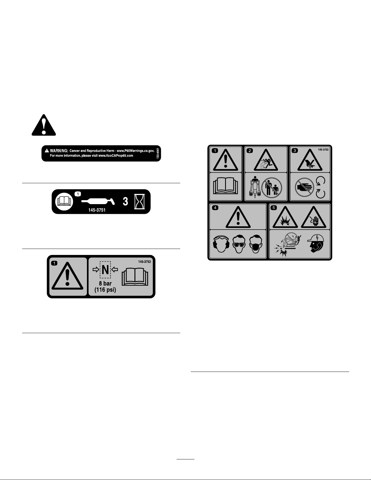
Consignesdesécuritépour
Autocollantsdesécuritéet
l'entretienetleremisage
•Contrôlezfréquemmentleserragedetoutesles
xationspourgarantirlefonctionnementsûrde
lamachine.
•ConsultezceManueldel'utilisateuravantde
remiserl'accessoirepouruneduréeprolongée
anden'oublieraucuneopérationimportante.
•Remplacezlesautocollantsd'instructionoude
sécuritémanquantsouendommagésaubesoin.
Desautocollantsdesécuritéetdesinstructionsbienvisiblesparl'opérateursontplacésprès
detouslesendroitspotentiellementdangereux.Remplaceztoutautocollantendommagé
oumanquant.
133-8061
d'instruction
decal133-8061
145-3751
1.LisezleManueldel'utilisateur;graissezlamachinetoutes
les3heures.
145-3752
1.Attention–Pressionmaximale8bar;lisezleManuelde
l'utilisateur.
decal145-3751
decal145-3752
1.Attention–lisezleManuel
del'utilisateur.
2.Risquedeprojection
d'objets–n'autorisez
personneàs'approcher.
3.Risquede
coupure/mutilation
desmains–nevous
approchezpasdespièces
mobiles.
decal145-3753
145-3753
4.Attention–portezdes
protecteursd'oreilles,une
protectionoculaireetune
protectionrespiratoire.
5.Risqued'explosionetde
chocélectrique–n'utilisez
paslamachine;contactez
lasociétédeservices
publicslocale.
5

Miseenservice
Vued'ensembledu
1
Installationdel'outil
Aucunepiècerequise
Procédure
VoirInstallationdel'outil(page9).
produit
Caractéristiques
techniques
Remarque:Lesspécicationsetlaconception
peuventfairel'objetdemodicationssanspréavis.
Largeur63cm
Longueur130cm
Hauteur33cm
Poids176kg
Longueurdetravaildel'outil29cm
Diamètredel'outil
Classed'énergied'impact
Fréquencedefrappe600à1150coups/min
Plagededébit
Outilsetaccessoires
5cm
339J
20à35l/minute
Unesélectiond'outilsetaccessoiresagréésparle
fabricantestdisponiblepouraugmenteretaméliorer
lescapacitésdelamachine.Pourobtenirlaliste
detouslesaccessoiresetoutilsagréés,contactez
votreconcessionnaire-réparateurouvotredistributeur
agréé,ourendez-voussurwww.Toro.com.
Pourgarantirunrendementoptimaletconserver
lacerticationdesécuritédelamachine,utilisez
uniquementdespiècesderechangeetaccessoires
d'origineT oro.Lespiècesderechangeetaccessoires
provenantd'autresconstructeurspeuventêtre
dangereux,etleurutilisationrisqued'annulerla
garantiedelamachine.
6
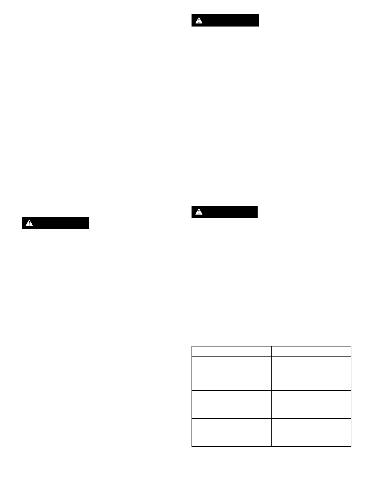
Utilisation
Important:Pourlesgroupesdedéplacement
série300,vousdevezinstallerlekitsoupape
desûretésurlegroupededéplacement
avantd'utiliserlebrise-béton.Vousrisquez
d'endommagerlegroupedéplacementsivous
n'installezpaslekit.Pourplusderenseignements,
contactezvotreconcessionnaire-réparateuragréé.
Poseetdéposede
l'accessoire
Reportez-vousauManueldel'utilisateurdugroupe
dedéplacementpourconnaîtrelaprocéduredepose
etdedépose.
Important:Avantd'installerl'accessoire,placez
lamachinesurunesurfaceplaneethorizontale,
vériezquelesplaquesdemontagesontpropres
etquelesgoupillestournentlibrement.Graissez
lesgoupillessiellesnetournentpaslibrement.
Remarque:Utiliseztoujourslegroupede
déplacementpourleveretdéplacerl'accessoire.
ATTENTION
Lesfuitesdeliquidehydrauliquesous
pressionpeuventtranspercerlapeauet
causerdesblessuresgraves.L'injection
deliquidesouslapeaunécessiteune
interventionchirurgicaledanslesheuresqui
suiventl'accident,réaliséeparunmédecin
connaissantcegenredeblessure,pouréviter
lerisquedegangrène.
•Vériezl'étatdetouslesexibleset
conduitshydrauliques,ainsiqueleserrage
detouslesraccordsetbranchements
avantdemettrelesystèmehydraulique
souspression.
•N'approchezpaslesmainsniaucune
autrepartieducorpsdesfuitesentrou
d'épingleoudesgicleursd'oùsortdu
liquidehydrauliquesoushautepression.
•Utilisezunmorceaudecartonoudepapier
pourdétecterlesfuiteshydrauliques,
jamaislesmains.
PRUDENCE
ATTENTION
L'accessoirepeutsedétacherdelamachine
etécraserquelqu'undanssachutesiles
goupillesnesontpascorrectementengagées
danslaplaquedemontage.
Vériezquelesgoupillessontcorrectement
engagéesdanslaplaquedemontage.
Lescoupleurshydrauliques,les
conduites/valveshydrauliquesetle
liquidehydrauliquepeuventêtretrèschauds,
etvousrisquezdevousbrûleràleurcontact.
•Portezdesgantspourdébrancherles
coupleurshydrauliques.
•Laissezrefroidirlamachineavantde
toucherlescomposantshydrauliques.
•Netouchezpasleliquidehydraulique
renversé.
Choixd'unoutil
Consultezletableausuivantpourchoisirl'outille
mieuxadaptépourlatâcheàaccomplir:
Outil
BurinplatPourtouslestravauxde
PointerollePourdémolirrocherset
Coupe-asphalte
terrassement,excavations
detranchéesétroites,sol
stratiéourochejusqu'àroche
moyenne.
matériaux(saufroche
stratiée)jusqu'àdureté
moyenne.
Pourdécouperles
revêtementsenasphalte,
lesmursdebriqueoule
gazon.
Utilisation
7
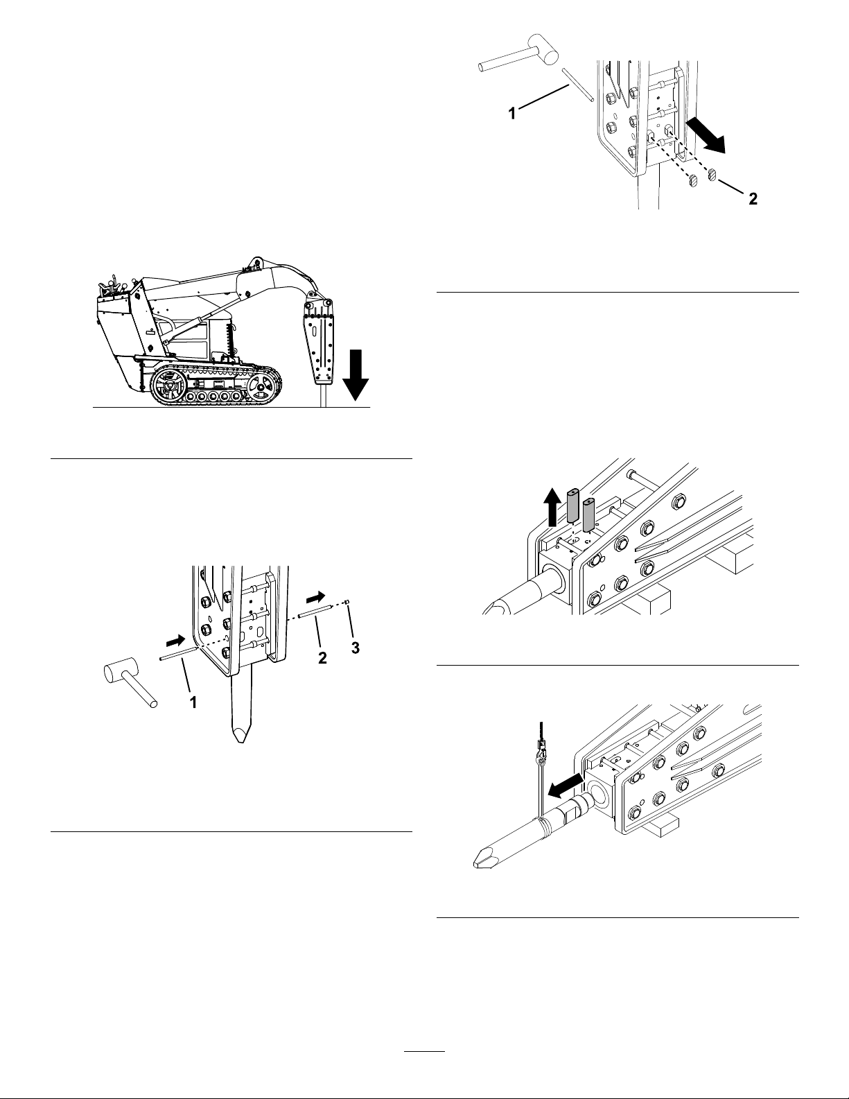
Remplacementdel'outil
Déposedel'outil
1.Garezlamachinesurunesurfaceplaneet
horizontale,etserrezlefreindestationnement
(lecaséchéant).
2.Levezlesbrasdechargeuseetbasculezle
brise-bétonàlaverticale.
3.Abaissezl'outilausolpourl'enfoncerdansle
brise-bétonjusqu'àcequ'ils'arrête.
Figure3
g359829
Figure5
1.Chasse-goupille2.Obturateurdegoupillede
retenue(2)
8.Déposezlesdispositifsdeblocagedesvérins
desbrasdechargeuse.
9.Abaissezlesbrasdechargeuseetplacezle
brise-bétonsurdescalesenbois.
10.Coupezlemoteuretenlevezlaclé.
g359140
11.Retirezlesgoupillesderetenueenleschassant
pardessousaveclechasse-goupille.
4.Coupezlemoteuretenlevezlaclé.
5.Montezlesdispositifsdeblocagedesvérins.
6.Avecunmarteauetlechasse-goupille,retirez
l'obturateuretlagoupilled'arrêtdel'outil.
Figure4
1.Chasse-goupille3.Obturateur
2.Goupilled'arrêt
7.Del'autrecôtédesobturateursdesgoupillesde
retenue,retirezles2obturateursdegoupille
avecunmarteauetlechasse-goupille.
g359830
Figure6
12.Déposezl'outil.
g358958
g359828
Figure7
Remarque:Neretirezpaslesgoupillesde
retenuesinonl'outilrisquedesedétacher.
8

Installationdel'outil
1.Assurez-vousquelebrise-bétonreposesurle
sol.
2.Graissezl'outiletl'intérieurdeladouille.
Figure8
1.Douille
3.Insérezl'outildanslecorpsdubrise-béton.
4.Insérezles2goupillesderetenue.
2.Outil
g358957
Figure11
1.Goupilled'arrêt2.Obturateur
g358954
6.Installezles2obturateursdesgoupillesde
retenue.
Figure9
5.Avecunmarteauetlechasse-goupille,installez
lagoupilled'arrêtetl'obturateur.
Important:Veillezàinsérercomplètement
l'obturateurdanslecorpsdubrise-béton,
commemontréàlaFigure11.
Figure10
g359804
Figure12
g358955
g358956
1.Obturateurdegoupillederetenue(2)
1.Goupilled'arrêt3.Chasse-goupille
2.Obturateur
9

Essayerlebrise-béton
Briserdesmatériaux
Important:Aprèsavoirinstallélebrise-béton
surunemachine,enparticulieraprèsrangement,
faitestoujoursunessaidefonctionnement
avantdel'utiliserand'évacuerl'airprésent
danslecircuitd'huile.L'utilisationsoudainedu
brise-bétonsansévacuerl'airapoureffetde
romprelelmd'huilecequiprovoquelegrippage
dubrise-béton.
1.Garezlamachinesurunesurfaceplaneet
horizontale,etserrezlefreindestationnement
(lecaséchéant).
2.Levezlesbrasdechargeuseetbasculezle
brise-bétonàlaverticale.Vériezquel'outilne
touchepaslesol.
Important:Lespercussionscontinuesaumême
emplacementpendantdespériodesprolongées
créedestempératuresélevéesàl'extrémitéde
l'outil.Celui-cipeutalorsperdredesadureté,
s'émoussesousl'effetduchocetnitparêtre
détruit.
1.Réglezlamachineaurégimeappropriépour
briserlematériau:
•Aveclesmodèlessérie300,travaillezau
régimemaximum,placezlesélecteurde
vitesseenpositiongammebasse(tortue)et
réglezlediviseurdedébitapproximativement
àlaposition10heures.
•Aveclese-Dingo,sélectionnezlemode
Marteaupourl'accessoire.
•AveclesmodèlessérieTX,travaillezau3/4
durégimemaximum.
2.Placezl'outildubrise-bétonde15à46cm
dedistanceduborddumatériauàbriser,en
l'inclinantà90degrés.
Figure13
3.Engagezlentementlesystèmehydraulique
avantjusqu'àcequelepistondubrise-béton
monte,puisinversezlesystèmehydraulique
avantl'impactdupiston.
Important:N'attendezpasl'impactdu
piston.
4.Voirlestempsdeduréedesessaispourles2
étapes.
Important:Nepermettezpasl'impactdu
pistonpendantletempsd'évacuationdel'air
etderécupérationdesjoints.
12
Temps
Brise-bétonneuf
Aprèsle
branchementdes
exibles,aucune
réparation
Aprèsréparation
dubrise-béton
d'évacuation
del'airetde
récupération
desjoints
15minutes
20minutes
Tempsde
préparation
Utilisezlamachine
pendant10minutes
à50%de
sonrégime
puis
pendant20minutes
à70%deson
régime.
g359139
g359138
Figure14
3.Exercezunepressionverslebasaveclesbras
dechargeusejusqu'àcequel'avantdugroupe
dedéplacementsesoulèved'environ5cm
au-dessusdusol.
Remarque:N'engagezlebrise-bétonque
lorsquel'outilestsurlesoletqu'unepression
verslebasestexercée.
Important:Assurez-vousquelesvérins
hydrauliquesontunecoursed'aumoins
5cm;n'utilisezpaslebrise-bétonavecles
vérinshydrauliquescomplètementdéployés.
4.Engagezlebrise-bétonetmaintenezlapression
verslebastandisquel'outilpénètredansle
matériauquevousbrisez.
5.Dèsquelematériauestbrisé,désengagezle
systèmehydrauliquepourarrêterdepercuter
lematériau
10
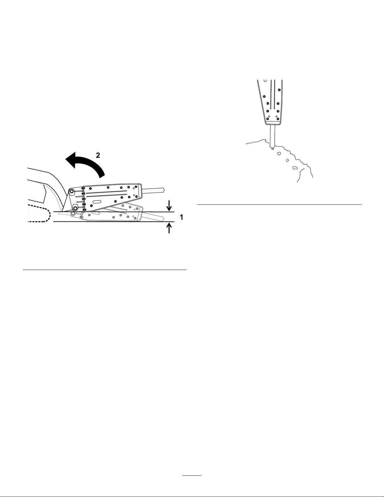
Briserunesurfaceverticale
1.Disposezl'outilsurlasurfaceverticalecomme
vousleferiezpourunesurfacehorizontale.
2.Maintenezlapressionsurl'outilenfaisant
avancerlegroupededéplacementdans
lasurfaceverticaletoutenactionnantle
brise-béton.
3.Abaissezrégulièrementlebrise-bétonà
laverticalepourfairetomberlesdébris
éventuellementaccumulésdedans.
Positiondetransport
Pourletransport,maintenezl'outilaussiprèsdusol
quepossible,àmoinsde15cmau-dessusdusol.
Inclinez-leenarrière.
•Denombreuxmatériauxsebrisentmals'ilssont
percutésdemanièrecontinueaumêmeendroit.
Chaquefoisquelebrise-bétonpénètrelematériau
sanslebriser,déplacez-leàunautrepointen
suivantuneligneparallèleauborddumatériau,à
environ7,6cmdutrouprécédent.Celaentaillele
matériauet,faitdemanièrerépétée,briseungros
morceaudumatériau.
g359750
Figure16
Figure15
1.Pasplusde15cm
au-dessusdusol
2.Basculerl'outilenarrière
Conseilsd'utilisation
•Sivousplacezl'outiltroploinduborddumatériau,
cedernierpeutabsorberl'énergieetresterintact.
•Silematériaunesebrisepasaprès1minute,
arrêtezlebrise-bétonetplacezl'outilàunautre
endroit.
•Necoincezpasl'outildanslematériauen
essayantdelebrisercarilpourraitêtrefaussé
ous'userprématurément.Appliquezlaforcesur
lebrise-bétondansl'axedel'outil,pasd'uncôté
àl'autreoud'avantenarrière.Celanécessitede
modierfréquemmentlapositiondugroupede
déplacement.
•Écoutezlesonproduitparlebrise-bétonen
marche.Lesonchangequandlapressionversle
basaugmente.Silapressionverslebasexercée
paslegroupededéplacementestinsufsante,
lemarteauproduiradessonsmétalliquesen
frappantl'outildelamauvaisemanière.
•Unepressionverslebasexcessiveproduit
desvibrationsprononcéesdanslegroupede
déplacement.
•Sivousbrisezdubétonarmé,montezunburin
platdanslebrise-bétonpourcouperlesarmatures
g359749
danslebéton.Vouspouvezaussicouperles
armaturesauchalumeau.
•Commentprolongerlaviedubrise-béton:
–Assurez-vousquelesvérinshydrauliquesont
unecoursed'aumoins5cm;n'utilisezpas
lebrise-bétonaveclesvérinshydrauliques
complètementdéployés.
–Nefaitesjamaislevieravecl'outildu
brise-béton.
–Évitezdepercuterlematériaubrutalement
avecl'outil.
–Nevousservezpasdubrise-bétonpour
souleveroudéplacerdesmatériaux.
–N'utilisezpaslebrise-bétonsousl'eau;seul
l'outildoitêtredansl'eau.
11

Entretien
PRUDENCE
Sivouslaissezlaclédanslecommutateurd'allumage,quelqu'unpourraitmettrelemoteuren
marcheaccidentellementetvousblessergravement,ainsiquetoutepersonneàproximité.
Avanttoutentretien,retirezlaclédecontact.
Programmed'entretienrecommandé
Périodicitéd'entretienProcédured'entretien
•Graissezl'outil.Graisseztoutesles3heuresd'utilisationetaprèschaquelavage.
•Vériezquelesconduiteshydrauliquesneprésententpasdefuites,nesontpas
Àchaqueutilisationou
unefoisparjour
pliées,usées,détérioréesparlesconditionsatmosphériquesoulesproduits
chimiques,etquelessupportsdemontageetlesraccordsnesontpasdesserrés.
•Contrôlezetresserreztouteslesxations.
•Vériezl'usureetleserragedesgoupillesdemontage,destrous,deladouillede
l'outiletdesgoupillesderetenue.Remettezenplaceouremplacezsinécessaire.
Toutesles40heures
Toutesles100heures
Avantleremisage
•Mesurezlalongueurdel'outilquandilestpoussédansleporte-outil.Remplacez
l'outils'ilfaitmoinsde200mm.
•Contrôlezlacharged'azotedansl'accumulateur.
•Peignezlessurfacesécaillées.
Graissagedel'outil
Périodicitédesentretiens:Àchaqueutilisationou
unefoisparjourGraisseztoutes
les3heuresd'utilisationetaprès
chaquelavage.
Typedegraisse:universelle
1.Garezlamachinesurunesurfaceplaneet
horizontale,etserrezlefreindestationnement
(lecaséchéant).
2.Inclinezlebrise-bétonjusqu'àcequ'ilsoit
verticaletabaissez-leausolpourenfoncerl'outil
danslebrise-bétonjusqu'àcequ'ils'arrête.
Important:Sivousn'enfoncezpasl'outil
danslebrise-bétonavantlegraissage,dela
graissepeutvenirremplirl'espaceentrele
hautdel'outiletlepistondubrise-béton.La
graisseseraalorsmisesouspressionpar
lepistoncequiendommageralejointàla
prochaineutilisationdubrise-béton.
3.Coupezlemoteuretenlevezlaclé.
4.Nettoyezlegraisseuravecunchiffon.
5.Raccordezunepompeàgraisseaugraisseur.
g359783
Figure17
6.Pompezdelagraissedanslegraisseurjusqu'à
cequ'ellecommenceàsuinterparladouille
inférieureetlagoupillederetenueouqu'il
deviennedifciled'actionnerlepistoletde
graissage.
7.Essuyeztoutexcèsdegraisse.
12

Contrôledelacharge
d'azote
Périodicitédesentretiens:T outesles100
heures—Contrôlezlacharge
d'azotedansl'accumulateur.
ATTENTION
Lebrise-bétoncomprendunechambre
remplied'azotesouspression,quipeut
explosersilescirconstancess'yprêtent,et
vousblesserouvoustuerainsiquetoute
personneàproximité.
•Nedémontezpaslecorpsdubrise-béton.
•N'essayezpasdechargerlachambrepar
vous-même.Porteztoujourslebrise-béton
chezunconcessionnaire-réparateuragréé
poureffectuerlacharge.
•Veillezàutiliserexclusivementdel'azote
pourchargerlebrise-béton.D'autresgaz
sontexplosifs.
•N'expédiezpaslebrise-bétonparavion.
Lebrise-bétoncomprendunaccumulateur,une
chambred'azotesouspression.Lapressionpeut
baisseraprèsplusieursheuresd'utilisation,cequi
réduitlesperformancesdubrise-béton.
Defortesvibrationsdanslesexibleshydrauliques
auxiliairessontunsignequelapressionbaissedans
lachambre.Sicelaseproduit,apportezlebrise-béton
àvotreconcessionnaire-réparateuragréépourlefaire
charger.
Pressiond'azote:8bar
1.Garezlamachinesurunesurfaceplaneet
horizontale,serrezlefreindestationnement
(selonl'équipement)etabaissezlebrise-béton
ausol.
2.Coupezlemoteuretenlevezlaclé.
g359809
Figure18
1.Valvedegaz3.Bouchondevalvedegaz
2.Manomètre
4.Insérezunmanomètredanslavalvedegazet
mesurezlapression.
5.Sielleestbasse,demandezàvotre
concessionnaire-réparateuragréédelacharger.
Contrôledesconduites
hydrauliques
Périodicitédesentretiens:Àchaqueutilisationou
unefoisparjour
ATTENTION
Lesfuitesdeliquidehydrauliquesous
pressionpeuventtranspercerlapeauet
causerdesblessuresgraves.L'injection
deliquidesouslapeaunécessiteune
interventionchirurgicaledanslesheuresqui
suiventl'accident,réaliséeparunmédecin
connaissantcegenredeblessure,pouréviter
lerisquedegangrène.
•N'approchezpaslesmainsniaucune
autrepartieducorpsdesfuitesentrou
d'épingleoudesgicleursd'oùsortdu
liquidehydrauliquesoushautepression.
3.Retirezlebouchondelavalvedegazsurla
protectionduvérin.
•Utilisezunmorceaudecartonoudepapier
pourdétecterlesfuiteshydrauliques,
jamaislesmains.
13

Remisage
d'unmois,évacuezlapressiondegaz:
8.Sivousprévoyezderemiserl'accessoireplus
Remisagedel'accessoire
1.Garezlamachinesurunesurfaceplaneet
horizontale,etserrezlefreindestationnement
(lecaséchéant).
2.Placezlebrise-bétonsur2calesenboisan
quelecôtéaveclevérinsoitplushautquele
côtéavecleporte-burin.
Figure19
A.Déposezl'outil;voirDéposedel'outil(page
8).
B.Évacuezl'azotedelaprotectionduvérin
parlavalvedegaz.
g359805
Figure21
1.Valvedegaz
C.Placezunbacdevidangesouslesexibles
etdesserrezlesbouchons.
g359808
3.Retirezl'accessoiredelamachine.
4.Lavezsoigneusementl'accessoireavecdel'eau
etundétergentdoux.
5.Contrôlezetresserreztouslesboulons,écrous
etvis.Réparezouremplacezlespièces
endommagéesouusées.
6.Peigneztouteslessurfacesmétalliques
éraéesoumisesànu.Unepeinture
pourretouchesestdisponiblechezles
concessionnaires-réparateursagréés.
7.Retirezlebouchonhexagonaletpulvérisezun
produitantirouilleautourdupiston.Remettezle
bouchonhexagonalenplace.
Figure22
1.Bouchondeexible
2.Tige
D.Insérezunetigedanslepistonet
enfoncez-ladélicatementavecunmarteau.
Remarque:Celaapoureffetd'évacuer
l'excédentd'azotedelachambrede
pression.
E.Resserrezlesbouchonsdesexibles.
F.Graissezl'outilestmettez-leenplace;voir
Installationdel'outil(page9).
9.Rangezlebrise-bétondansunendroitpropre
etsec,commeungarageouuneremise.
Couvrez-lapourlaprotégeretlagarderpropre.
g359807
1.Bouchonhexagonal
Figure20
10.Avantderemettrelebrise-pistonen
g359806
14
service,remplacezl'azote;contactezvotre
concessionnaire-réparateuragréé.

Dépistagedesdéfauts
ProblèmeCausepossible
Duliquidehydrauliquefuit.
Unefuitedeplusde10bard'azotese
produittoutesles100heures.
Lebrise-bétonneproduitpasd'impacts.
Lebrise-bétonfrappedemanière
erratique.
Mesurecorrective
1.Unarrêtd'huile,unjointtoriqueou
unebagued'appuiestusé(e)ou
endommagé(e).
2.Lepistonoulecylindreestgrippé.
3.L'écroudelabiellette,lebouchon
d'étranglementoul'adaptateurde
exibleestdesserré.
1.Unjointtorique,unpistonouunjoint
estuséouendommagé.
2.Lepistonoulecylindreestgrippé.
1.Latempératureduliquidehydraulique
esttropbasse.
2.Lapressiond'azotedanslachambre
esttropélevée.
3.Lavalved'arrêtestfermée.3.Ouvrezlavalved'arrêt.
4.Lapressionestrégléetropbaspourla
soupapedesûreté.
5.Lapompehydrauliquefonctionnemal.5.Contactezunconcessionnaire-
1.Lavannedecommande,lepistonou
levérinestgrippé.
2.Lapressionestrégléetropbaspourla
soupapedesûreté.
3.Lapompehydrauliquefonctionnemal.
4.Lapressionverslebassurl'outilest
insufsante.
5.Lapressiond'azotedanslachambre
esttropélevée.
1.Contactezunconcessionnaireréparateuragréé.
2.Contactezunconcessionnaireréparateuragréé.
3.Resserrezlapiècedesserrée.
1.Contactezunconcessionnaireréparateuragréé.
2.Contactezunconcessionnaireréparateuragréé.
1.Réchauffezlebrise-béton.
2.Évacuezlapressionpourlaramener
auniveaucorrect.
4.Contactezunconcessionnaireréparateuragréé.
réparateuragréé.
1.Contactezunconcessionnaireréparateuragréé.
2.Contactezunconcessionnaireréparateuragréé.
3.Contactezunconcessionnaireréparateuragréé.
4.Augmentezlapressionverslebassur
l'outil.
5.Évacuezlapressionpourlaramener
auniveaucorrect.
Lebrise-bétonmanquedepuissance.1.Lapressiond'azotedanslachambre
Lebrise-bétonneproduitpasd'impacts.
esttropbasse.
1.Lapressiond'azotedanslachambre
esttropélevée.
2.Lapressionverslebassurl'outilest
insufsante.
3.Lapressionestrégléetropbaspourla
soupapedesûreté.
4.Lapompehydrauliquefonctionnemal.
5.Unexiblehydrauliqueestbouché.
1.Contactezunconcessionnaireréparateuragréé.
1.Évacuezlapressionpourlaramener
auniveaucorrect.
2.Augmentezlapressionverslebassur
l'outil.
3.Contactezunconcessionnaireréparateuragréé.
4.Contactezunconcessionnaireréparateuragréé.
Retirezl'obstructionouremplacezle
5.
exible.
15

Déclarationd'incorporation
TheT oroCompany,8111LyndaleAve.South,Bloomington,MN,USAdéclarequelaoulesmachinessuivantes
sontconformesauxdirectivesmentionnées,lorsqu'ellessontmontéesenrespectantlesinstructionsjointessur
certainsmodèlesTorocommeindiquédanslesDéclarationsdeconformitépertinentes.
N°de
modèle
23136321000001etsuivants
N°desérie
Descriptionduproduit
Brise-béton,porte-outils
compacts
DescriptiondelafactureDescriptiongénérale
HYDRAULICBREAKER,
DINGO
Porte-outilcompact
LadocumentationtechniquepertinenteaétécompiléecommeexigéparlaPartieBdel'AnnexeVIIde
ladirective2006/42/CE.
Nousnousengageonsàtransmettre,àlasuited'unedemandedûmentmotivéedesautoritésnationales,les
renseignementspertinentsconcernantcettequasi-machine.Laméthodedetransmissionseraélectronique.
Cetéquipementneserapasmisenserviceavantd'avoirétéincorporédanslesmodèlesT oroagréés
conformémentàlaDéclarationdeconformitéassociéeetàtouteslesinstructions,cequipermettradele
déclarerconformeàtouteslesdirectivespertinentes.
Certié:
MichaelBenedict
Directeurtechnique
811 1LyndaleAve.South
Bloomington,MN55420,USA
Juillet13,2021
Représentantautorisé:
MarcelDutrieux
ManagerEuropeanProductIntegrity
ToroEuropeNV
Nijverheidsstraat5
2260Oevel
Belgium
Directive
2006/42/CE

DéclarationdecondentialitéEEE/R-U
UtilisationdevosdonnéespersonnellesparT oro
LasociétéTheToroCompany(«Toro»)respectevotrevieprivée.Lorsquevousacheteznosproduits,nouspouvonsrecueillircertainesdonnées
personnellesvousconcernant,soitdirectementsoitparl'intermédiairedevotresociétéouconcessionnaireTorolocal(e).Toroutilisecesdonnéespour
s'acquitterd'obligationscontractuelles,parexemplepourenregistrervotregarantie,traiteruneréclamationautitredelagarantieouvouscontacterdans
l'éventualitéd'unrappeldeproduit,maisaussiàdesnscommercialeslégitimes,parexemplepourmesurerlasatisfactiondesclients,améliorernos
produitsouvoustransmettredesinformationssurlesproduitssusceptiblesdevousintéresser.Toropourrapartagerlesdonnéespersonnellesque
vousluiaurezcommuniquéesavecsesliales,concessionnairesouautrespartenairescommerciauxdanslecadredecesactivités.Nouspourrons
aussiêtreamenésàdivulguerdesdonnéespersonnellessilaloil'exigeoudanslecadredelacession,del'acquisitionoudelafusiond'unesociété.
Nousnevendronsjamaisvosdonnéespersonnellesàaucuneautresociétéauxnsdemarketing.
Conservationdevosdonnéespersonnelles
Toroconserveravosdonnéespersonnellesaussilongtempsquenécessairepourrépondreauxnssusmentionnéesetconformémentauxdispositions
légalesapplicables.Pourplusderenseignementsconcernantlesduréesdeconservationapplicables,veuillezcontacterlegal@toro.com.
L'engagementdeToroenmatièredesécurité
VosdonnéespersonnellespourrontêtretraitéesauxÉtats-Unisoudanstoutautrepaysoùlalégislationconcernantlaprotectiondesdonnéespeutêtre
moinsrigoureusequecelledevotreproprepaysderésidence.Chaquefoisquenoustransféreronsvosdonnéespersonnelleshorsdevotrepays
derésidence,nousprendronstouteslesdispositionslégalesrequisespourmettreenplacetouteslesgarantiesnécessairesvisantàlaprotectionet
autraitementsécurisédevosdonnées.
Droitsd'accèsetderectication
Vouspouvezêtreendroitdecorrigeroudevériervosdonnéespersonnelles,ouencoredevousopposerautraitementdevosdonnées,oud'enlimiter
laportée.Pourcefaire,veuilleznouscontacterparcourrielàlegal@toro.com.SivousavezlamoindreinquiétudeconcernantlamanièredontT oroa
traitévosdonnéespersonnelles,nousvousencourageonsànousenfairepartdirectement.Veuilleznoterquelesrésidentseuropéensontledroit
deporterplainteauprèsdeleurAutoritédeprotectiondesdonnées.
374-0282RevC

Proposition65deCalifornie–Informationconcernantcetavertissement
Enquoiconsistecetavertissement?
Certainsproduitscommercialisésprésententuneétiquetted'avertissementsemblableàcequisuit:
AVERTISSEMENT:Cancerettroublesdelareproduction–
www.p65Warnings.ca.gov.
Qu'est-cequelaProposition65?
LaProposition65s'appliqueàtoutesociétéexerçantsonactivitéenCalifornie,quivenddesproduitsenCalifornieouquifabriquedesproduits
susceptiblesd'êtrevendusouimportésenCalifornie.EllestipulequeleGouverneurdeCaliforniedoitteniretpublierunelistedessubstances
chimiquesconnuescommecausantdescancers,malformationscongénitaleset/ouautrestroublesdelareproduction.Cetteliste,quiestmiseàjour
chaqueannée,comprenddescentainesdesubstanceschimiquesprésentesdansdenombreuxobjetsduquotidien.LaProposition65apourobjet
d'informerlepublicquantàl'expositionàcessubstanceschimiques.
LaProposition65n'interditpaslaventedeproduitscontenantcessubstanceschimiques,maisimposelaprésenced'avertissementssurtoutproduit
concerné,sursonemballageousurladocumentationfournieavecleproduit.D'autrepart,unavertissementdelaProposition65nesigniepasqu'un
produitesteninfractionaveclesnormesouexigencesdesécuritéduproduit.D'ailleurs,legouvernementcalifornienaclairementindiquéqu'un
avertissementdelaProposition65«n'estpasunedécisionréglementairequantaucaractère«sûr»ou«dangereux»d'unproduit».Bonnombre
decessubstanceschimiquessontutiliséesdansdesproduitsduquotidiendepuisdesannées,sansaucuneffetnocifdocumenté.Pourplusde
renseignements,rendez-voussurhttps://oag.ca.gov/prop65/faqs-view-all
UnavertissementdelaProposition65signiequ’unesociétéasoit(1)évaluél'expositionetconcluqu'elledépassaitle«niveauneposantaucun
risquesignicatif»;soit(2)choisid'émettreunavertissementsimplementsurlabasedesacompréhensionquantàlaprésenced'unesubstance
chimiquedelaliste,sanstenterd'enévaluerl'exposition.
.
Cettelois’applique-t-ellepartout?
LesavertissementsdelaProposition65sontexigésuniquementenvertudelaloicalifornienne.Cesavertissementssontprésentsdanstoutl'état
deCalifornie,dansdesenvironnementstrèsvariés,notammentmaispasuniquementlesrestaurants,magasinsd'alimentations,hôtels,écoles
ethôpitaux,etsurunvasteéventaildeproduits.Enoutre,certainsdétaillantsenligneetparcorrespondancefournissentdesavertissementsdela
Proposition65surleurssitesinternetoudansleurscatalogues.
QuellesdifférencesentrelesavertissementsdeCalifornieetleslimitesfédérales?
LesnormesdelaProposition65sontsouventplusstrictesquelesnormesfédéralesetinternationales.Diversessubstancesexigentunavertissement
delaProposition65àdesniveauxbieninférieursauxlimitesd'interventionfédérales.Parexemple,lanormedelaProposition65enmatière
d'avertissementspourleplombsesitueà0,5µg/jour,soitbienmoinsquelesnormesfédéralesetinternationales.
Pourquoil'avertissementnegure-t-ilpassurtouslesproduitssemblables?
•PourlesproduitscommercialisésenCalifornie,l'étiquetageProposition65estexigé,tandisqu'ilnel'estpassurdesproduitssimilaires
commercialisésailleurs.
•Ilsepeutqu'unesociétéimpliquéedansunprocèsliéàlaProposition65etparvenantàunaccordsoitobligéed'utiliserlesavertissementsdela
Proposition65poursesproduits,tandisqued'autressociétésfabriquantdesproduitssemblablespeuventnepasêtresoumisesàcetteobligation.
•L'applicationdelaProposition65n'estpasuniforme.
•Certainessociétéspeuventchoisirdenepasindiquerd'avertissementscarellesconsidèrentqu'ellesn'ysontpasobligéesautitredela
Proposition65;l'absenced'avertissementssurunproduitnesigniepasqueleproduitnecontientpasdesubstancesdelalisteàdesniveaux
semblables.
Pourquoicetavertissementapparaît-ilsurlesproduitsToro?
Toroachoisidefournirauxconsommateursleplusd'informationpossibleanqu'ilspuissentprendredesdécisionséclairéesquantauxproduits
qu'ilsachètentetutilisent.Torofournitdesavertissementsdanscertainscasd'aprèssesconnaissancesquantàlaprésencedel'uneouplusieurs
dessubstanceschimiquesdelaliste,sansenévaluerleniveaud'exposition,cardesexigencesdelimitesnesontpasfourniespourtouslesproduits
chimiquesdelaliste.Bienquel'expositionaveclesproduitsT oropuisseêtrenégligeableouparfaitementdansleslimites«sansaucunrisque
signicatif»,parmesuredeprécaution,T oroadécidédefournirlesavertissementsdelaProposition65.Deplus,enl'absencedecesavertissements,
lasociétéToropourraitêtrepoursuivieenjusticeparl'ÉtatdeCalifornieoupardesparticulierscherchantàfaireappliquerlaProposition65,et
doncassujettieàd'importantespénalités.
RevA
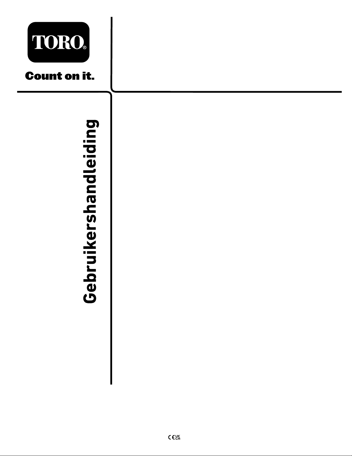
FormNo.3447-321RevA
Betonbreker
Compactewerktuigdragers
Modelnr.:23136—Serienr.:321000001enhoger
Registreeruwproductopwww .Toro.com.
Vertalingvandeoorspronkelijketekst(NL)
*3447-321*
WAARSCHUWING
CALIFORNIË
Proposition65Waarschuwing
Gebruikvanditproductkanleidentot
blootstellingaanchemischestoffen
waarvandeStaatCaliforniëweetdatze
kanker,geboorteafwijkingenenandere
schadeaanhetvoortplantingssysteem
veroorzaken.
Inleiding
Dezebetonbrekerisbedoeldvoorgebruikmeteen
Torocompactewerktuigdrager.Hijishoofdzakelijk
ontworpenvoorhetbrekenvanbeton,asfalt,steenof
baksteentijdensrenovatiewerkzaamheden.
g360512
Figuur1
1.Plaatsvanmodelnummerenserienummer
Modelnr.:
Leesdezeinformatiezorgvuldigdoor,zodatuweet
hoeuditproductopdejuistewijzemoetgebruikenen
onderhoudenenomletselenschadeaandemachine
tevoorkomen.Ubentverantwoordelijkvoorhetjuiste
enveiligegebruikvandemachine.
Ganaarwww.T oro.comvoordocumentatieover
productveiligheidenbedieningsinstructies,informatie
overaccessoires,hulpbijhetvindenvaneendealer
ofomuwproductteregistreren.
Alsuservice,origineleT oroonderdelenofaanvullende
informatienodighebt,kuntucontactopnemenmet
eenerkendeservicedealerofmetdeklantenservice
vanT oro.Udienthierbijaltijdhetmodelnummeren
hetserienummervanhetproducttevermelden.Het
model-enserienummerstaanopeenplaatjegedrukt
datzichaanderechterzijdevandeaandrijfkop
bevindt.Ukuntdenummersnotereninderuimte
hieronder.
Belangrijk:Ukuntmetuwmobielapparaatde
QR-codeophetplaatjemethetserienummer
(indienaanwezig)scannenomtoegangte
krijgentotdegarantie,onderdelenenandere
productinformatie.
Serienr.:
Erwordenindezehandleidingeenaantalmogelijke
gevareneneenaantalveiligheidsberichtengenoemd
metdevolgendeveiligheidssymbolen(Figuur2),
dieduidenopeengevaarlijkesituatiediezwaar
lichamelijkletselofdedoodtotgevolgkanhebbenals
udeveiligheidsvoorschriftennietinachtneemt.
g000502
Figuur2
1.Veiligheidssymbool
Erwordenindezehandleidingtweewoordengebruikt
omuwaandachtopbijzondereinformatietevestigen.
Belangrijkattendeertuopbijzonderetechnische
informatieenOpmerkingduidtalgemeneinformatie
aandiebijzondereaandachtverdient.
©2021—TheToro®Company
8111LyndaleAvenueSouth
Bloomington,MN55420
Ukuntcontactmetonsopnemenopwww.Toro.com.
2
Allerechtenvoorbehouden
GedruktindeVS

Inhoud
Veiligheid
Veiligheid..................................................................3
Algemeneveiligheid...........................................3
Veiligheidophellingen........................................4
Veiligheidbijhetomgaanmetde
betonbreker.....................................................4
Veiligheidtijdensonderhoudenopslag...............5
Veiligheids-eninstructiestickers........................5
Montage....................................................................6
1Deboormonteren............................................6
Algemeenoverzichtvandemachine.........................6
Specicaties......................................................6
Werktuigen/accessoires.....................................6
Gebruiksaanwijzing..................................................7
Monterenenverwijderenvanhet
werktuig..........................................................7
Eengereedschapselecteren..............................7
Deboorvervangen.............................................8
Debetonbrekertesten......................................10
Materiaalbreken...............................................10
Eenverticaaloppervlakbreken..........................11
Transportstand..................................................11
Tipsvoorbedieningengebruik..........................11
Onderhoud..............................................................12
Aanbevolenonderhoudsschema.........................12
Deboorsmeren................................................12
Destikstoadingcontroleren............................13
Hydraulischeleidingencontroleren...................13
Stalling....................................................................14
Hetwerktuigopslaan........................................14
Problemen,oorzaakenremedie.............................15
GEVAAR
Mogelijklopenerinuwwerkgebiedonder
grondleidingenvannutsbedrijven.Alsudeze
beschadigt,kandatelektrischeschokkenof
eenexplosieveroorzaken.
Zorgdatdeondergrondsekabelsen
leidingengemarkeerdwordenopde
locatieofinhetwerkgebiedenontwijkde
gemarkeerdegebieden.Neemcontactop
metdeplaatselijkemarkeringsdienstofhet
betreffendenutsbedrijfomdelocatietelaten
markeren(belbijvoorbeeldindeVerenigde
Staten811ofinAustralië1100voorde
nationalemarkeringsdienst).
Algemeneveiligheid
Volgaltijdalleveiligheidsinstructiesopomernstigof
mogelijkdodelijkletseltevoorkomen.
•Transporteereenwerktuignooitalsdearmen
omhoogstaan.Transporteerhetwerktuigaltijd
dichtbijdegrond;zieTransportstand(bladz.11).
•Zorgdatdeondergrondsekabels,leidingenen
andereobjectengemarkeerdwordenopdelocatie
ofinhetwerkgebiedengaopdezeplaatsenniet
graven.
•LeesdezeGebruikershandleidingenzorgervoor
datudezebegrijptvoordatudemotorstart.
•Geefuwvolledigeaandachtalsudemachine
gebruikt.Zorgervoordatumetnietsandersbezig
bentwaardoorukuntwordenafgeleid,anders
kanerletselontstaanofkaneigendomworden
beschadigd.
•Laatkinderenofpersonendiegeeninstructie
hebbenontvangendemachinenooitgebruiken.
•Houduwhandenenvoetenuitdebuurtvande
bewegendeonderdelenenwerktuigen.
•Gebruikdemachineenkelalsdeschermenen
anderebeveiligingsmiddelenaanwezigzijnen
naarbehorenwerken.
•Houomstandersenhuisdierenuitdebuurtvan
demachine.
•Schakeldemachineuit,zetdemotor
afenverwijderhetsleuteltjevoordatu
onderhoudswerkzaamhedenuitvoert,bijtanktof
verstoppingenuitdemachineverwijdert.
Onjuistgebruikofonderhoudvandezemachine
kanletseltotgevolghebben.Omhetrisicoop
letselteverkleinen,dientuzichaandevolgende
veiligheidsinstructiestehoudenenaltijdophet
3

veiligheidssymboolteletten,datbetekent
Voorzichtig,WaarschuwingofGevaar–instructie
voorpersoonlijkeveiligheid.Niet-nalevingvandeze
instructieskanleidentotlichamelijkofdodelijkletsel.
•Weesvoorzichtigalsudemachinegebruiktinde
buurtvan:
–Steilehellingen
–Greppels
Veiligheidophellingen
•Rijdemachineheuvelopwaartsen
heuvelafwaartsmethetzwareuiteindenaarde
topvandeheuvelgericht.Degewichtsverdeling
verandertinfunctievandewerktuigen.Dit
werktuigmaaktdevoorzijdevandemachinetot
hetzwareuiteinde.
•Laathetwerktuigneeralsuophellingenrijdt.
Alsuhetwerktuigomhoogbrengtopeenhelling,
heeftditinvloedopdestabiliteitvandemachine.
•Hellingenzijndebelangrijksteoorzaakdatde
bestuurderdecontroleoverdemachineverliest
endezeomkantelt.Ditkanleidentoternstig
ofdodelijkeletsel.Gebruikvandemachineop
hellingenofoneffenterreinvereistaltijdextra
voorzichtigheid.
•Steluweigenproceduresenvoorschriftenopvoor
werkenophellingen.Alsonderdeelvandeze
proceduresmoetuzekerhetterreinonderzoeken
omnategaanopwelkehellingenudemachine
veiligkuntgebruiken.Gebruikaltijduwgezond
verstandenuwbeoordelingsvermogenwanneeru
ditonderzoekuitvoert.
•Verminderuwsnelheidenweesextravoorzichtig
ophellingen.Detoestandvandegrondkanvan
invloedzijnopdestabiliteitvandemachine.
•Nietstartenofstoppenopeenhelling.Alsde
machinegripverliest,rijddehellingdanlangzaam
ineenrechtelijnaf.
•Maakgeenbochtenopeenhelling.Alsueen
bochtmoetmaken,moetuditlangzaamdoenen
dezwarekantvandemachineheuvelopwaarts
gerichthouden.
•Gaopeenhellingaltijdlangzaamenbehoedzaam
tewerk.Verandernietplotselingdesnelheidofde
rijrichtingvandemachine.
•Alsuzichongemakkelijkvoeltwanneerude
machineopeenhellinggebruikt,maaidiehelling
danniet.
•Letopkuilen,vorenofbulten,omdatdekans
bestaatdatdemachineomslaatopongelijkterrein.
Inhooggraszijnobstakelsnietaltijdzichtbaar.
•Weesvoorzichtigalsuopeennatteondergrond
werkt.Alsdemachinegripverliest,kandezegaan
glijden.
•Inspecteerhetterreinomerzekervantezijndat
degrondstabielgenoegisomdemachinete
ondersteunen.
–Dijkenentaluds
–Water
Demachinekanplotselingomslaanalseen
rupsbandoverderandkomt,ofalsderandinstort.
Houdeenveiligeafstandtussendemachineen
eengevarenzoneaan.
•Umaggeenwerktuigenverwijderenof
aankoppelenopeenhelling.
•Parkeerdemachinenietopeenhelling.
Veiligheidbijhetomgaan
metdebetonbreker
•Draagpersoonlijkebeschermingsmiddelen(PBM)
engeschiktekleding,waaronder:
–Eenhelm
–Eenstofmasker
–Eenveiligheidsbril
–Gehoorbescherming
–Stevigeschoenenmetantislipzool
–Eenlangebroek
–Eenshirtmetlangemouwendiestrakaande
polsenzijn
–Nauwsluitendehandschoenenzonder
trekkoordenoflossemanchetten
•Voortractie-eenhedenmetwielenmoetuhet
contragewichtmonterenwanneeruhetwerktuig
gebruikt.
•Houddetractie-eenheiduitdebuurtvanderand
diewordtgebroken.
•Breekgeenmateriaaldatzichrechtstreeksonder
devoorkantvandetractie-eenheidbevindt.
•Indebrekerbevindtzicheenkamermetstikstof
onderdruk,datonderdejuisteomstandigheden
kanontploffen.Demonteerdebehuizingvande
brekerniet.
•Probeerdebufferkamernietzelfteladen.Neem
contactopmetuwerkendeservicedealeri.v.m.
hetladen.
•Zorgervoordatdebetonbrekerenkelmetstikstof
wordtgeladen.
•Verzenddegeladenbetonbrekernietvia
luchtvracht.
4

Veiligheidtijdens
Veiligheids-en
onderhoudenopslag
•Controleerregelmatigofallebevestigingen
vastzittenenhetveiligisomdeinstallatiete
gebruiken.
•RaadpleegdezeGebruikershandleidingvoor
belangrijkedetailsalsudemachinegedurende
langetijdgaatstallen.
•Zorgervoordatdeveiligheids-eninstructiestickers
ingoedestaatzijnenvervangzeindiennodig.
Veiligheidsstickersenveiligheidsinstructieszijngemakkelijkzichtbaarvoordebestuurderen
bevindenzichbijplaatsenwaargevaarkanontstaan.Vervangallebeschadigdeofverdwenen
stickers.
133-8061
instructiestickers
decal133-8061
145-3751
1.LeesdeGebruikershandleiding;smeerdemachineomde
drieuur.
145-3752
1.Waarschuwing–Maximaledruk8bar;leesde
Gebruikershandleiding.
decal145-3751
decal145-3752
1.Waarschuwing–Leesde
Gebruikershandleiding.
2.Machinekanvoorwerpen
uitwerpen–Houd
omstandersuitdebuurt
3.Handenkunnenworden
gesneden/geamputeerd
–Blijfuitdebuurtvan
bewegendeonderdelen.
decal145-3753
145-3753
4.Waarschuwing–Draag
gehoor-,oog-en
ademhalingsbescherming.
5.Gevaarvoorontplofng
enelektrischeschok
–Gebruikdemachine
niet;beluwplaatselijk
nutsbedrijf.
5

Montage
Algemeenoverzicht
1
Deboormonteren
Geenonderdelenvereist
Procedure
ZieDeboormonteren(bladz.9).
vandemachine
Specicaties
Opmerking:Specicatiesenontwerpkunnen
zondervoorafgaandekennisgevingwordengewijzigd.
Breedte63cm
Lengte130cm
Hoogte33cm
Gewicht
Bedrijfslengtevanboor
Diametervanboor
Klassevanslagenergie339J
Aantalslagen600tot1 150bpm
Stroombereik
Werktuigen/accessoires
ErzijneenaantalgoedgekeurdeTorowerktuigen
enaccessoiresverkrijgbaaromdemogelijkheden
vandemachineuittebreiden.Neemcontactop
meteenerkendeservicedealerofeenerkendeToro
distributeur,ofbezoekwww.T oro.comvooreenlijst
vanallegoedgekeurdewerktuigenenaccessoires.
176kg
29cm
5cm
20tot35literperminuut
Omdebesteprestatiesteverkrijgenenervoor
tezorgendatdeveiligheidscerticatenvande
machineblijvengelden,moetutervervanging
altijdorigineleonderdelenenaccessoiresvanToro
aanschaffen.Gebruiktervervangingnooitonderdelen
enaccessoiresvananderefabrikanten,omdat
ditgevaarlijkkanzijnendeproductgarantiekan
tenietdoen.
6
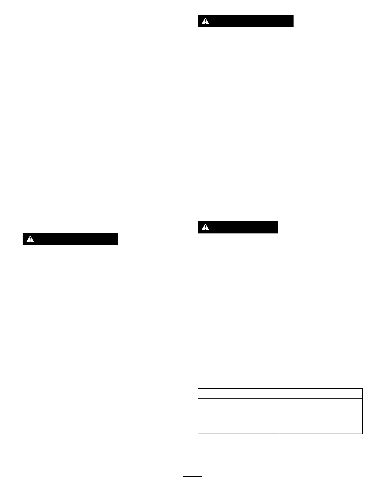
Gebruiksaanwijzing
Belangrijk:Bij300-serietractie-eenhedenmoet
uervoorzorgendatudeontlastklepmonteert
opuwtractie-eenheidvoordatudebetonbreker
gebruikt.Indienunalaatomdezetemonteren,kan
dituwtractie-eenheidbeschadigen.Neemvoor
verdereinformatiecontactopmetuwerkende
servicedealer.
Monterenenverwijderen
vanhetwerktuig
RaadpleegdeGebruikershandleiding
vandetractie-eenheidvoormontage-en
demontageprocedure.
Belangrijk:Voordatuhetwerktuigmonteert,
moetudemachineopeenhorizontaaloppervlak
plaatsen,ervoorzorgendatdebevestigingsplaten
vrijvanvuilzijnencontrolerenofdepennen
onbelemmerdronddraaien.Alsdepennennietvrij
ronddraaien,moetenzegesmeerdworden.
WAARSCHUWING
Hydraulischevloeistofdieonderdruk
ontsnapt,kandoordehuidheendringen
enletselveroorzaken.Vloeistofdieinde
huidisgeïnjecteerd,dientbinnenenkele
urenoperatieftewordenverwijderddoor
eenartsdiebekendismetdezevormvan
verwondingen,omdaterandersgangreenkan
ontstaan.
•Controleerofallehydraulischeslangen
enleidingeningoedestaatverkerenen
allehydraulischeaansluitingenenttings
stevigvastzittenvoordatudrukzetophet
hydraulischesysteem.
•Houdlichaamenhandenuitdebuurtvan
kleinelekgatenofspuitmondenwaaruit
onderhogedrukhydraulischevloeistof
ontsnapt.
•Ukuntlekkeninhethydraulischesysteem
opsporenmetbehulpvankartonofpapier;
doeditnooitmetuwhanden.
Opmerking:Gebruikaltijddetractie-eenheidom
hetwerktuigoptetillenenteverplaatsen.
WAARSCHUWING
Alsdesnelkoppelingspennennietvolledig
indebevestigingsplatenzitten,bestaatde
kansdathetwerktuigvandemachinevalt,
waardooruofomstandersbekneldkunnen
raken.
Zorgervoordatdesnelkoppelingspennen
volledigindebevestigingsplatenzitten.
VOORZICHTIG
Hydraulischekoppelingen,hydraulische
leidingen/kleppenenhydraulischevloeistof
kunnenheetzijn.Ukuntzichverbrandenals
uheteonderdelenaanraakt.
•Draaghandschoenenalsudehydraulische
koppelingenlosmaakt.
•Laatdemachineafkoelenvoordatude
hydraulischeonderdelenaanraakt.
•Zorgervoordatunietinaanrakingkomt
metgemorstehydraulischevloeistof.
Eengereedschap
selecteren
Gebruikdevolgendetabelomhetmeestgeschikte
gereedschapvoorgebruiktekiezen:
Gereedschap
BeitelTegebruikenvooralle
grondverzetwerkzaamheden,
uitgravingeninsmallesleuven,
gelaagdegrondofgemiddelde
rotsen.
Toepassing
7

PuntbeitelV oorhetslopenvanrotsen
enmaterialen,niet-gelaagd
gesteente,totgemiddelde
hardheid.
AsfaltfreesVoorhetfrezenvan
asfalt,bakstenenmuren
ofgraszoden.
Deboorvervangen
Deboorverwijderen
1.Parkeerdemachineopeenhorizontaalvlak
ensteldeparkeerreminwerking(indienvan
toepassing).
2.Brengdearmenvandeladeromhoogenkantel
debetonbrekerzodatdezeverticaalstaat.
3.Laatdebooropdegrondzakkenomdezeinde
brekerteduwentotdezestopt.
endeboorpenverwijderaaromdetwee
borgpenpluggenteverwijderen.
Opmerking:Verwijderdeborgpennenniet,
anderskandebooreruitvallen.
Figuur5
1.Boorpenverwijderaar
8.Verwijderdecilindervergrendelingenvande
armenvandelader.
9.Brengdearmenvandeladeromlaagenplaats
debetonbrekerophoutenblokken.
2.Borgpenplug(2)
g359829
Figuur3
4.Zetdemotorafenhaalhetsleuteltjeuithet
contact.
5.Brengdecilindervergrendelingenaan.
6.Gebruikeenhamerendeboorpenverwijderaar
omdestopendestoppenteverwijderen.
10.Zetdemotorafenhaalhetsleuteltjeuithet
contact.
11.Gebruikdeboorpenverwijderaarvanonderde
borgpennenomdepennenteverwijderen.
g359140
g359830
Figuur6
12.Deboorverwijderen.
Figuur4
1.Boorpenverwijderaar
2.Stoppen
3.Stop
7.V andetegenovergesteldekantvande
borgpenpluggengebruiktueenhamer
g358958
g359828
Figuur7
8

Deboormonteren
1.Zorgervoordatdebetonbrekersteuntopde
grond.
2.Smeerdeboorendebinnenkantvande
lagerbusvandeboor.
g358956
Figuur10
Figuur8
1.Lagerbusvandeboor2.Boor
3.Steekdeboorindebehuizingvande
betonbreker.
4.Monteerde2borgpennen.
Figuur9
1.Stoppen
2.Stop
g358954
3.Penverwijderaar
g358957
Figuur11
1.Stoppen2.Stop
6.Monteerde2borgpenpluggen.
g358955
5.Gebruikeenhamerendeboorpenverwijderaar
omdestopendestoppentemonteren.
Belangrijk:Zorgervoordatdestopvolledig
indebehuizingzitzoalsgetoondinFiguur
11.
g359804
Figuur12
1.Borgpenplug(2)
9

Debetonbrekertesten
Materiaalbreken
Belangrijk:Nadatudebetonbrekeropeen
machinehebtgemonteerd,vooralnaopslag,moet
udebrekeraltijdtestenvoordatumateriaalbreekt
omluchtuithetoliecircuittelatenontsnappen.
Indienudebetonbrekerplotsgebruiktzonderde
luchttelatenontsnappen,breektdeolielmendit
veroorzaaktvastlopenvandebetonbreker.
1.Parkeerdemachineopeenhorizontaalvlak
ensteldeparkeerreminwerking(indienvan
toepassing).
2.Brengdearmenvandeladeromhoogenkantel
debetonbrekerzodatdezeverticaalstaat.Zorg
ervoordatdeboordegrondnietraakt.
Belangrijk:Voortdurendengedurendelange
periodenopdezelfdeplaatsinslaanveroorzaakt
hogetemperaturenaandepuntvandeboor.Dit
kanertoeleidendatdeboorhaarhardheidverliest
enwordtvervormd,waardoordeboorwordt
vernietigd.
1.Steldegashendelvooruwmachineinzodat
dezepastvoorhetbrekenvanmateriaal:
•Voormachinesvande300-seriemoetu
volgasgebruiken(maximummotortoerental),
moetdetoerentalhendelindelagestand
wordengezet(schildpadstand)enmoet
destroomverdelingsklepongeveerinde
10-uurpositiewordengezet.
•Voore-Dingomachines,moetu
dewerktuigmodusveranderennaar
hamermodus.
•VoorTX-seriemachines,moetu¾gas
gebruiken.
2.Plaatsdeboorvandebrekerbinnen15tot
46cmvanderandvanhetmateriaaldatmoet
wordengebroken,ineenhoekvan90graden.
Figuur13
3.Schakeldevoorwaartsehydraulieklangzaamin
totdatdebrekerzuigeromhoogkomt,endraai
dehydrauliekdanlangzaamterugvoordatde
zuigerinslaat.
Belangrijk:Laatdezuigernietinslaan.
4.Raadpleegdetabelvoordetesttijdenvoorde
2stadia.
Belangrijk:Laatdezuigernietinslaan
tijdensdetijddatdeluchtwordtverwijderd
endeafdichtingwordthersteld.
12
Nieuwebreker
Nadatdeslangen
zijnaangesloten,
geenherstellingen
Naherstellingen
aandebetonbreker
Tijddatdelucht
wordtverwijderd
endeafdichting
wordthersteld
15minuten
20minuten
Voorberei-
dingstijd
Gebruikde
machine
gedurende
10minuten
op50%gas
endan
20minutenop
70%gas
g359139
g359138
Figuur14
3.Oefenneerwaartsedrukuitmetdearmenvande
ladertotdatdevoorkantvandetractie-eenheid
ongeveer5cmvandegrondkomt.
Opmerking:Schakeldebrekernietintenzijde
boorzichopdegrondbevindtenerneerwaartse
drukwordtuitgeoefend.
Belangrijk:Zorgervoordatdehydraulische
cilinderstenminste5cmslaghebben;
gebruikdebetonbrekernietmetvolledig
uitgeschovenhydraulischecilinders.
4.Schakeldebrekerinenbehouddeneerwaartse
drukterwijldeboorzicheenwegbaantinhette
brekenmateriaal.
5.Wanneerhetmateriaalgebrokenis,moetu
dehydrauliekonmiddellijkuitschakelenomte
stoppenmethetslaaninhetmateriaal.
10

Eenverticaaloppervlak
breken
1.Plaatsdeboorophetverticaleoppervlakop
dezelfdemanieralsuhetzouplaatsenopeen
horizontaaloppervlak.
2.Behouddedrukopdeboordoorde
tractie-eenheidvooruitterijdeninhetverticale
oppervlakterwijludebrekergebruikt.
3.Laatdebrekerregelmatiginverticalepositie
zakken,zodatpuindatzichmogelijkindebreker
heeftverzameld,eruitkanvallen.
Transportstand
Bijhettransporterenvanhetwerktuigmoetuditzo
laagmogelijkbovendegrondhouden,nietmeerdan
15cmbovendegrond.Kantelhetwerktuignaar
achteren.
neerwaartsedrukafneemt.Alsdeneerwaartse
drukvandeeenheidtezwakis,zultu
metaalachtigeslagenvandehamerhoren
wanneerdezeverkeerdopdeboorslaat.
•Eenovermatigeneerwaartsedrukproduceert
sterketrillingenindeeenheid.
•Veelmaterialenbrekennietgoedbijvoortdurend
hamerenop1plaats.T elkenswanneerdebreker
hetmateriaalbinnendringtzonderhettebreken,
moetudebrekerverplaatsennaareennieuwe
plekineenlijnevenwijdigaanderandvanhet
materiaal,ongeveer7,6cmvanhetvorigegat.
Hierdoorwordthetmateriaalbeschadigden,
indienherhaaldelijkgedaan,breekteengrootstuk
vanhetmateriaalaf.
Figuur15
1.Nietmeerdan15cm
bovendegrond
2.Werktuignaarachteren
kantelen.
Tipsvoorbedieningen
gebruik
•Alsdeboorzichtevervanderandvanhet
materiaalbevindt,kanhetmateriaaldeenergie
absorberenennietbreken.
•Alshetmateriaalnietbreektna1minuut,stopde
brekerdanenzetdebooropeenanderelocatie.
•Zorgervoordatdeboornietvastkomttezitten
inhetmateriaaldatwordtgebroken,anderskan
deboorwordenverbogenofvoortijdigverslijten.
Zorgervoordatallekrachtdieopdebrekerwordt
uitgeoefendinlijnismetdeboor,nietzijwaarts
ofvoorwaartsnaarachteren.Ditvereistdatude
positievandetractie-eenheidfrequentaanpast.
g359750
Figuur16
g359749
•Alsumetbetonijzergewapendbetonbreekt,
gebruiktueenbeitelbitindebrekeromdoorde
betonijzersinhetbetontebreken.Ukunthet
betonijzerookdoorsnijdenmeteenlasbrander.
•Omdelevensduurvandebrekerteverlengen:
–Zorgervoordatdehydraulischecilinders
tenminste5cmslaghebben;gebruikde
betonbrekernietmetvollediguitgeschoven
hydraulischecilinders.
–Gebruikdeboorvandebrekernietals
hefboom.
–Voorkomdatumetdeboorabruptophet
materiaalslaat.
–Gebruikdebrekernietommateriaalopte
heffenofteverplaatsen.
–Gebruikdebrekernietonderwater;laatenkel
deboorinhetwaterkomen.
•Luisternaarhetgeluidvandebrekerwanneer
dezewerkt.Hetgeluidverandertwanneerde
11
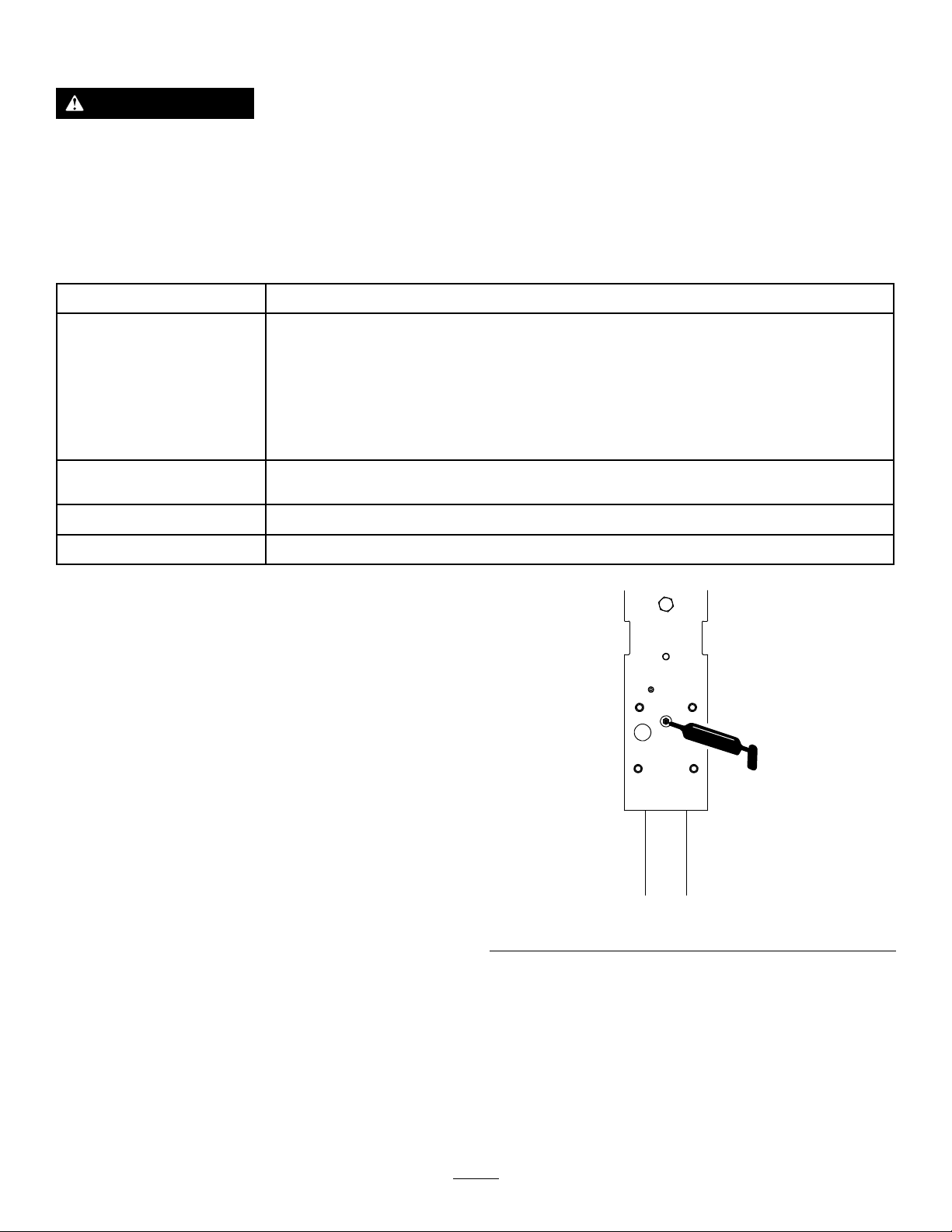
Onderhoud
VOORZICHTIG
Alsuhetsleuteltjeinhetcontactlaat,bestaatdekansdatiemanddemotorperongelukstart
waardooruenandereomstandersernstigletselkunnenoplopen.
Verwijderhetsleuteltjeuithetcontactvoordatuonderhoudswerkzaamhedenuitvoertaande
machine.
Aanbevolenonderhoudsschema
OnderhoudsintervalOnderhoudsprocedure
•Deboorsmeren.Smeeromde3uurennaelkeschoonmaakbeurt.
•Controleerdehydraulischeleidingenoplekkages,losgeraakteaansluitingen,
kinken,loszittendesteunen,slijtage,beschadigingenalsgevolgvanweersinvloeden
Bijelkgebruikofdagelijks
endeinwerkingvanchemicaliën.
•Controleerallebevestigingenendraaidezevast.
•Controleerofdemontagepennen,deopeningen,delagerbusvandeboorende
borgpennenloszittenenofzeversletenzijn.Maakzevastenvervangzeindien
nodig.
Omde40bedrijfsuren
Omde100bedrijfsuren
Vóórdestalling
•Meetdeboorlengtewanneerdezeindeboorhouderisgedrukt.Vervangdeboorals
degemetenlengteminderisdan200mm.
•Destikstoadingindeaccumulatorcontroleren.
•Beschadigdeoppervlakkenbijwerken.
Deboorsmeren
Onderhoudsinterval:Bijelkgebruikofdagelijks
Smeeromde3uurennaelke
schoonmaakbeurt.
Typevet:universeelsmeervet
1.Parkeerdemachineopeenhorizontaalvlak
ensteldeparkeerreminwerking(indienvan
toepassing).
2.Kanteldebrekerzodatdezeverticaalstaat
enlaathemzakkenopdegrondomdeboor
omhoogteduwenindebrekertotdezestopt.
Belangrijk:Alsudeboornietindebreker
duwtvoordatusmeert,kanhetvetderuimte
tussendebovenkantvandeboorende
zuigervandebrekeropvullen.Hierdoor
komthetvetindezuigeronderdruktestaan
enwordtdeafdichtingbijhetvolgende
gebruikvandebrekerbeschadigd.
3.Zetdemotorafenhaalhetsleuteltjeuithet
contact.
4.Maakdesmeernippelschoonmeteenlap.
g359783
Figuur17
6.Spuitvetindesmeernippeltothetvetuitde
onderstelagerbusendeborgpenbeginttelopen
oftotdathetpompenmetdevetspuitmoeilijk
wordt.
7.Veegovertolligvetweg.
5.Plaatseenvetspuitopdesmeernippel.
12

Destikstoading
controleren
Onderhoudsinterval:Omde100bedrijfsuren—De
stikstoadingindeaccumulator
controleren.
WAARSCHUWING
Indebrekerbevindtzicheenkamer
metstikstofonderdruk,dieonderde
juisteomstandighedenkanontploffenen
(dodelijk)letselkantoebrengenaanuofaan
omstanders.
•Demonteerdebehuizingvandebrekerniet.
•Probeerdekamernietzelfteladen.
Brengdebrekeraltijdnaareenerkende
servicedealervoorhetladen.
•Zorgervoordatdebetonbrekerenkelmet
stikstofwordtgeladen.Anderegassen
kunnenontploffen.
•Verzenddegeladenbetonbrekernietvia
luchtvracht.
Aandebinnenkantvandebrekerziteenaccumulator,
eenkamermetstikstofonderdruk.Naverschillende
urenvangebruikkandedrukafnemen,waardoorde
prestatiesvandebrekerverminderen.
Sterketrillingenindeslangenvandehulphydrauliek
zijneentekendatdedrukindekamerdaalt.Alsdit
zougebeuren,moetudebrekernaaruwerkende
servicedealerbrengenomtewordengeladen.
Drukvanstikstofgas:8bar
1.Plaatsdemachineopeenhorizontaaloppervlak,
steldeparkeerreminwerking(indienvan
toepassing)enlaatdebrekerneeropdegrond.
2.Zetdemotorafenhaalhetsleuteltjeuithet
contact.
3.Verwijderdegasklepafsluitervande
cilinderovertrek.
g359809
Figuur18
1.Gasklep3.Gasklepasluiter
2.Drukmeter
4.Plaatseendrukmeterindegasklepenmeetde
druk.
5.Alsdedruklaagis,moetucontactopnemen
meteenerkendeservicedealeromdebreker
teladen.
Hydraulischeleidingen
controleren
Onderhoudsinterval:Bijelkgebruikofdagelijks
WAARSCHUWING
Hydraulischevloeistofdieonderdruk
ontsnapt,kandoordehuidheendringen
enletselveroorzaken.Vloeistofdieinde
huidisgeïnjecteerd,dientbinnenenkele
urenoperatieftewordenverwijderddoor
eenartsdiebekendismetdezevormvan
verwondingen,omdaterandersgangreenkan
ontstaan.
•Houdlichaamenhandenuitdebuurtvan
kleinelekgatenofspuitmondenwaaruit
onderhogedrukhydraulischevloeistof
ontsnapt.
•Ukuntlekkeninhethydraulischesysteem
opsporenmetbehulpvankartonofpapier;
doeditnooitmetuwhanden.
13
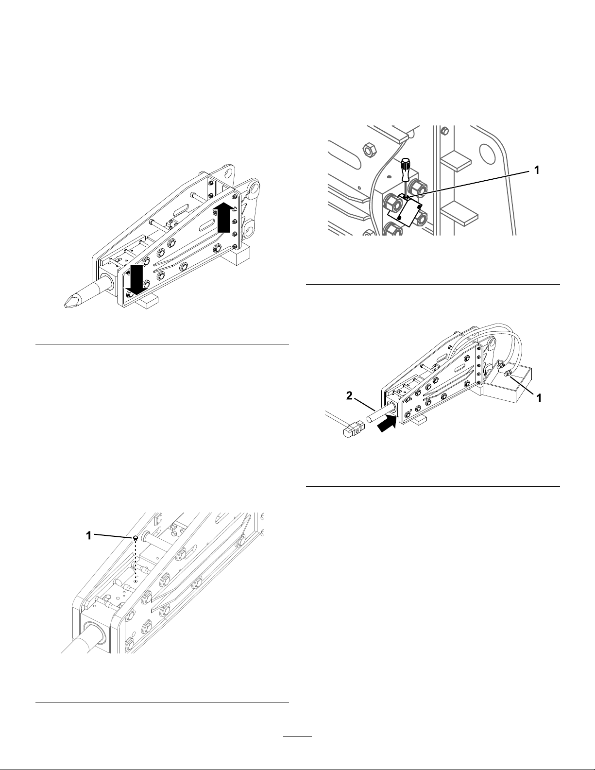
Stalling
opgeslagen,moetudedrukvanhetgasvanhet
werktuiglaten:
8.Alshetwerktuiglangerdan30dagenzalworden
Hetwerktuigopslaan
1.Parkeerdemachineopeenhorizontaalvlak
ensteldeparkeerreminwerking(indienvan
toepassing).
2.Plaatsdebrekerop2stukkenhoutzodatde
kantmetdecilinderhogerisdandekantmetde
beitelhouder.
Figuur19
A.Verwijderdeboor;zieDeboorverwijderen
(bladz.8).
B.Laathetstikstofgasuitdecilinderovertrek
ontsnappenviadegasklep.
g359805
Figuur21
1.Gasklep
C.Plaatseenopvangbakonderdeslangenen
g359808
maakdepluggenlos.
3.Verwijderhetwerktuigvandemachine.
4.Washetwerktuigmeteenmildreinigingsmiddel
enwateromvuilenroetteverwijderen.
5.Controleerallebouten,schroevenenmoeren
endraaidezevast.Repareerofvervang
beschadigdeofversletenonderdelen.
6.Werkallekrassenenbeschadigingenvandelak
bij.Bijwerklakisverkrijgbaarbijeenerkende
servicedealer.
7.Verwijderdezeskantplugenspuitantiroestspray
inhetzuigergebied.Plaatsdezeskantplug.
g359807
Figuur22
1.Slangplug2.Stang
D.Plaatseenstangindezuigerenduwdeze
ervoorzichtiginmeteenhamer.
Opmerking:Hierdoorkomtovertollig
stikstofgasuitdebufferkamervrij.
E.Maakdeslangpluggenvast.
F.Smeerdeboorenmonteerze;zieDeboor
monteren(bladz.9).
9.Staldebrekerineenschone,drogegarageof
opslagruimte.Dekhetwerktuigafomhette
beschermenenschoontehouden.
g359806
Figuur20
1.Zeskantplug
10.Wanneerudebrekeruitdeopslaghaalt,moet
uhetstikstofgasvervangenvoordatuhem
ingebruikneemt;neemcontactopmetuw
erkendeservicedealer.
14

Problemen,oorzaakenremedie
ProbleemMogelijkeoorzaakRemedie
Dehydraulischevloeistoflekt.
Meerdan10barstikstofgaslektelke
100uur .
Debrekerslaatnietin.
Debrekerslaatonregelmatigin.
1.Eenoliepakking,O-ringofback-upring
isversletenofbeschadigd.
2.Dezuigerofcilinderisvastgelopen.
3.Demoervandetrekstang,chokeplug
ofslangadapterzitlos.
1.EenO-ring,zuigerofafdichtingis
versletenofbeschadigd.
2.Dezuigerofcilinderisvastgelopen.
1.Detemperatuurvandehydraulische
vloeistofistelaag.
2.Dedrukvanhetstikstofgasinde
kameristehoog.
3.Hetstopventielisgesloten.
4.Dedrukinstellingvoordeontlastklep
istelaag.
5.Dehydraulischepomppresteertslecht.5.Neemcontactopmeteenerkende
1.Deregelklep,dezuigerofdecilinder
isvastgelopen.
2.Dedrukinstellingvoordeontlastklep
istelaag.
3.Dehydraulischepomppresteertslecht.3.Neemcontactopmeteenerkende
4.Erisnietgenoegneerwaartsedrukop
deboor .
5.Dedrukvanhetstikstofgasinde
kameristehoog.
1.Neemcontactopmeteenerkende
servicedealer.
2.Neemcontactopmeteenerkende
servicedealer.
3.Zethetloszittendeonderdeelvast.
1.Neemcontactopmeteenerkende
servicedealer.
2.Neemcontactopmeteenerkende
servicedealer.
1.Warmdebrekerop.
2.Laatdegasdrukophetjuisteniveau
komen.
3.Openhetstopventiel.
4.Neemcontactopmeteenerkende
servicedealer.
servicedealer.
1.Neemcontactopmeteenerkende
servicedealer.
2.Neemcontactopmeteenerkende
servicedealer.
servicedealer.
4.Oefenmeerneerwaartsedrukuitop
deboor .
5.Laatdegasdrukophetjuisteniveau
komen.
Debrekerheeftteweinigvermogen.
Debrekerslaatnietaan.
1.Dedrukvanhetstikstofgasinde
kameristelaag.
1.Dedrukvanhetstikstofgasinde
kameristehoog.
2.Erisnietgenoegneerwaartsedrukop
deboor .
3.Dedrukinstellingvoordeontlastklep
istelaag.
4.Dehydraulischepomppresteertslecht.4.Neemcontactopmeteenerkende
5.Eriseenobstructieineenhydraulische
slang.
1.Neemcontactopmeteenerkende
servicedealer.
1.Laatdegasdrukophetjuisteniveau
komen.
2.Oefenmeerneerwaartsedrukuitop
deboor .
3.Neemcontactopmeteenerkende
servicedealer.
servicedealer.
5.Verwijderdeobstructieofvervangde
slang.
15

Inbouwverklaring
TheToroCompany,8111LyndaleAve.South,Bloomington,MN,VSverklaartdatdevolgende
eenheid/eenhedenvoldoet/voldoenaandevermelderichtlijnenalszevolgensdebijgeleverdeinstructies
gemonteerdwordenopbepaaldeToro-machines,zoalsbeschreveninderelevanteconformiteitsverklaringen.
Modelnr.:
23136321000001enhoger
Serienr.:
ProductbeschrijvingFactuuromschrijvingAlgemeneomschrijvingRichtlijn
Betonbreker,compacte
werktuigdragers
HYDRAULICBREAKER,
DINGO
Compactewerktuigdrager2006/42/EG
DerelevantetechnischedocumentatiewerdsamengesteldinovereenstemmingmetDeelBvanBijlageVII
vanrichtlijn2006/42/EG.
Wijbelovenopvraagvannationaleoverhedenrelevanteinformatieoverdezegedeeltelijkafgewerktemachine
overtedragen.Ditzalgebeurenviaelektronischeweg.
DezemachinemagpasinwerkingwordengesteldalszegeïntegreerdisineengoedgekeurdT oromodelzoals
beschreveninhettoegevoegdegelijkvormigheidsattesteninovereenstemmingmetalleinstructies,waardoor
menervankanuitgaandatzeinovereenstemmingismetallerelevanterichtlijnen.
Gecerticeerd:
MichaelBenedict
Technischdirecteur
811 1LyndaleAve.South
Bloomington,MN55420,USA
juli13,2021
Erkendevertegenwoordiger:
MarcelDutrieux
ManagerEuropeanProductIntegrity
ToroEuropeNV
Nijverheidsstraat5
2260Oevel
Belgium

PrivacyverklaringEEA/VK
Toro'sgebruikvanuwpersoonlijkegegevens
TheT oroCompany(“Toro”)respecteertuwrechtopprivacy.Wanneeruonzeproductenkoopt,kunnenwebepaaldepersoonlijkeinformatieoveru
verzamelen,ofwelrechtstreeksviauofwelviauwplaatselijkT orobedrijfofdealer.Torogebruiktdezeinformatieomtevoldoenaancontractuele
verplichtingen–zoalshetregistrerenvanuwgarantie,hetbehandelenvanuwgarantieclaimofomcontactmetuoptenemeninhetgevalvan
terugroepacties–envoorlegitiemezakelijkedoeleinden–zoalsklanttevredenheidmeten,onzeproductenverbeterenofuproductinformatieverschaffen
dievanbelangkanzijn.Torokanuwinformatiedelenmetonzedochterondernemingen,verdelersofanderezakenpartnersinverbandmetdeze
activiteiten.Wekunnenookpersoonlijkeinformatievrijgevenvanrechtswegeofinverbandmetdeverkoop,aankoopoffusievaneenbedrijf.We
verkopenuwpersoonsgegevensnooitaananderebedrijvenvoormarketingdoeleinden.
Hoeuwpersoonlijkeinformatiebewaardwordt
Torobewaartuwpersoonlijkeinformatiezolangdezerelevantisvoordebovengenoemdedoeleindeneninovereenstemmingismetdewettelijke
vereisten.Gelievecontactoptenemenvialegal@toro.comvoormeerinformatieoverdebewaarperiodesdievantoepassingzijn.
Toro'sengagementinzakeveiligheid
UwpersoonlijkeinformatiekanbehandeldwordenindeVSofeenanderlanddatmogelijksoepeleredatabeschermingswettenheeftdanhetlandwaar
uverblijft.Indienweuwinformatieoverdragennaareenanderlanddanhetlandwaaruverblijft,nemenwijdewettelijkverplichtemaatregelenom
ervoortezorgendatdeinformatieopgepastewijzewordtbeschermdenveiligwordtbehandeld.
Toegangencorrectie
Uhebthetrechtomuwpersoonlijkegegevenstecorrigerenofteraadplegen,ofzichteverzettentegendeverwerkingvanuwgegevensofdezete
beperken.Omdezerechtenuitteoefenen,gelieveeene-mailtesturennaarlegal@toro.com.AlsuzichzorgenmaaktoverdemanierwaaropT orouw
informatieheeftbehandeld,vragenwijuomdezedirecttenaanzienvanonsteuiten.Europeseburgershebbenhetrechtomeenklachtintedienen
bijhungegevensbeschermingsautoriteit.
374-0282RevC

CaliforniaProposition65waarschuwing–alleenvoorCalifornië
Watiseenwaarschuwing?
Sommigeproductendieopdemarktzijnbevatteneenetiketmeteenwaarschuwingals:
WAARSCHUWING:Kankerenschadeaandevoortplantingsorganen–
www.p65Warnings.ca.gov.
WatisProp65?
Prop65geldtvoorelkbedrijfdatactiefisinCalifornië,productenverkooptinCalifornië,ofproductenmaaktdiekunnenwordenverkochtofgeïmporteerd
inCalifornië.DewetschrijftvoordatdeGouverneurvanCaliforniëeenlijstvanchemischestoffenbijhoudtenpubliceertwaarvanbekendisdatze
kanker,geboorteafwijkingenen/ofandereschadeaandevoortplantingsorganenkunnenveroorzaken.Delijstwordtjaarlijksbijgewerktenomvat
honderdenchemischestoffendieinveelalledaagsevoorwerpenvoorkomen.Prop65heeftalsdoelmensenteinformerenoverblootstellingaan
dezechemischestoffen.
Prop65verbiedtdeverkoopvanproductendiedezechemicaliënbevattenniet;welschrijftdewetvoordathetproduct,deproductverpakkingende
bijgevoegdedocumentatiewaarschuwingenbevatten.EenProp65-waarschuwingbetekentooknietdateenproductenigenormofvereisteinzake
productveiligheidschendt.DeCalifornischeregeringsteltduidelijkdateenProp65-waarschuwing“nietneerkomtopeenwettelijkebeslissingdateen
product‘veilig’of‘onveilig’is.”Veelvandezechemischestoffenwordenaljarenopgroteschaalenzondergedocumenteerdeschadegebruiktin
alledaagsevoorwerpen.Gavoormeerinformatienaarhttps://oag.ca.gov/prop65/faqs-view-all
EenProp65-waarschuwingbetekentdat(1)eenbedrijfdeblootstellingheeftbeoordeeldenvanmeningisdatdezehetniveau‘geensignicant
risico’overschrijdt,ofdat(2)hetbedrijfkiestomeenwaarschuwingtevermeldenomdathetweetdateenbetreffendechemischestofaanwezigis,
zonderevenweldeblootstellingeraantebeoordelen.
.
Isdezewetoveralvankracht?
Prop65-waarschuwingenzijnenkelvereistkrachtensdeCalifornischewet.DezewaarschuwingenzietmeninheelCaliforniëinuiteenlopende
omgevingen,bijvoorbeeldinrestaurants,kruidenierswinkels,hotels,scholen,ziekenhuizenenopeengrootaantalproducten.Daarnaastkiezensommige
webverkopersenpostorderbedrijvenervooromProp65-waarschuwingentegevenophunwebsiteofincatalogi.
HoeverschillendeCalifornischewaarschuwingenvandefederalegrenswaardes?
DeProp65-voorschriftenzijnvaakstrikterdanfederaleeninternationalenormen.VoorverschillendestoffenisinCaliforniëalbijveellageredosisseneen
waarschuwingvereistdaneldersindeVS.Bijvoorbeeld:deProp65-normvoorwaarschuwingenvoorloodbedraagt0,5microgramperdag,watveel
minderisdandefederaleeninternationalestandaarden.
Waaromhebbennietallevergelijkbareproductendezewaarschuwing?
•ProductendieverkochtwordeninCaliforniëmoetenvoorzienwordenvaneenProp65-aanduiding,maarditgeldtnietvoorvergelijkbare
productenopandereplaatsen.
•EenbedrijfkaninnavolgingvaneenrechtszaakverplichtwordenomzijnproductentevoorzienvanProp65-waarschuwingen,terwijlditvoor
anderebedrijvendievergelijkbareproductenverkopennietgeldt.
•Prop65wordtnieteenduidigopgelegd.
•Bedrijvenkunnenervoorkiezengeenwaarschuwingtevermeldenomdatzevindendatzedaarniettoeverplichtzijninhetkadervande
Prop65-voorschriften;ookalsergeenwaarschuwingenopeenproductstaan,ishetbestmogelijkdatdebetreffendechemischeproductentoch
invergelijkbaredosissenaanwezigzijn.
WaaromvermeldtTorodezewaarschuwing?
Torowilconsumentenzogoedmogelijkinformerenzodatzegeïnformeerdebeslissingenkunnennemenoverdeproductendiezekopenengebruiken.
Torovermeldtinsommigegevallenwaarschuwingenopbasisvanzijnkennisoverdeaanwezigheidvanéénofmeervandebetreffendechemische
stoffen,zonderevenwelhetniveauvanblootstellingtebeoordelen,aangeziennietallebetreffendechemischestoffenvoorzienzijnvanvoorschriften
voorblootstellingslimieten.OokalisdeblootstellingdoorproductenvanToroverwaarloosbaarofvaltdezeruimbinnendecategorie'geensignicant
risico',heeftT oroerveiligheidshalvevoorgekozenomProp65-waarschuwingenoptenemen.AlsT orodezewaarschuwingennietvermeldt,zouhet
bovendienvervolgdkunnenwordendoordeStaatCaliforniëofdoorprivatepersonendietenuitvoerleggingvanProp65beogen,enhetkanopdie
manieraanzienlijkeboeteskrijgen.
RevA
 Loading...