

Page 1
LowFlowAuxiliaryKit
TX1000CompactUtilityLoader
ModelNo.23134
ThisproductcontainsachemicalorchemicalsknowntotheStateofCaliforniato
causecancer,birthdefects,orreproductiveharm.
Safety
SafetyandInstructionalDecals
FormNo.3401-682RevB
InstallationInstructions
WARNING
CALIFORNIA
Proposition65Warning
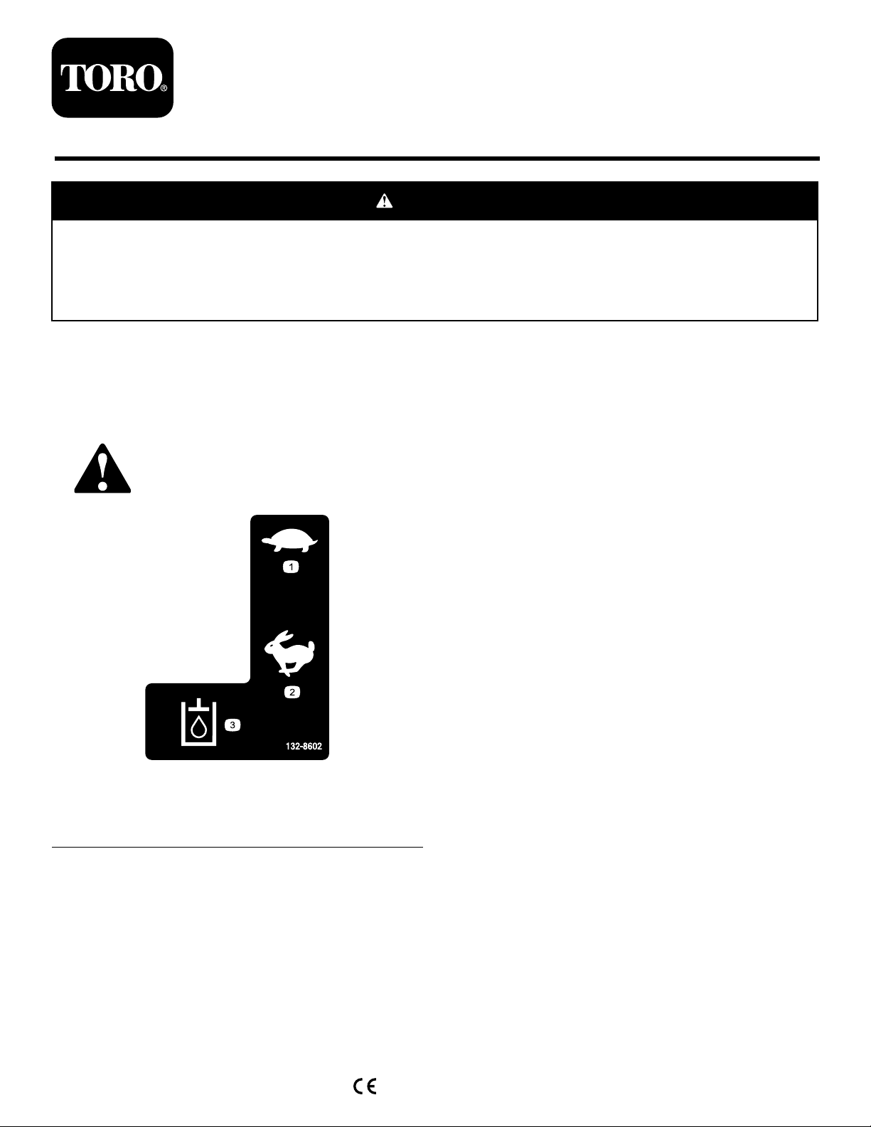
Safetydecalsandinstructionsareeasilyvisibletotheoperatorandarelocatednearanyareaofpotential
danger.Replaceanydecalthatisdamagedormissing.
132-8602
1.Slow3.Hydraulicuid
2.Fast
decal132-8602
©2016—TheT oro®Company
8111LyndaleAvenueSouth
Bloomington,MN55420
Registeratwww.T oro.com.
OriginalInstructions(EN)
PrintedintheUSA
AllRightsReserved
*3401-682*B
Page 2
Installation
LooseParts
Usethechartbelowtoverifythatallpartshavebeenshipped.
ProcedureDescription
1
2
3
4
5
Nopartsrequired
Nopartsrequired
Nopartsrequired
Low-owvalve
Bracket1
Bolt(1/4x2-1/2inches)
Locknut(1/4inch)
Straighttting
45-degreetting
90-degreetting
U-shapedtube1
Loaderarmtting
Teetube1
90-degreetube1
Curvedtube
Hydraulichose1
Hoseprotector1
Cabletie
Switch
Decal1
Wireharness1
Qty.
Use
–
–
–
1
2
2
2
2
2
1
1
3
1
Preparethemachine.
Disconnectthebattery .
Removetheexistinghoses.
Installthevalveassembly.
Installtheswitchandwireharness.
2
Page 3
1
PreparingtheMachine
NoPartsRequired
Procedure
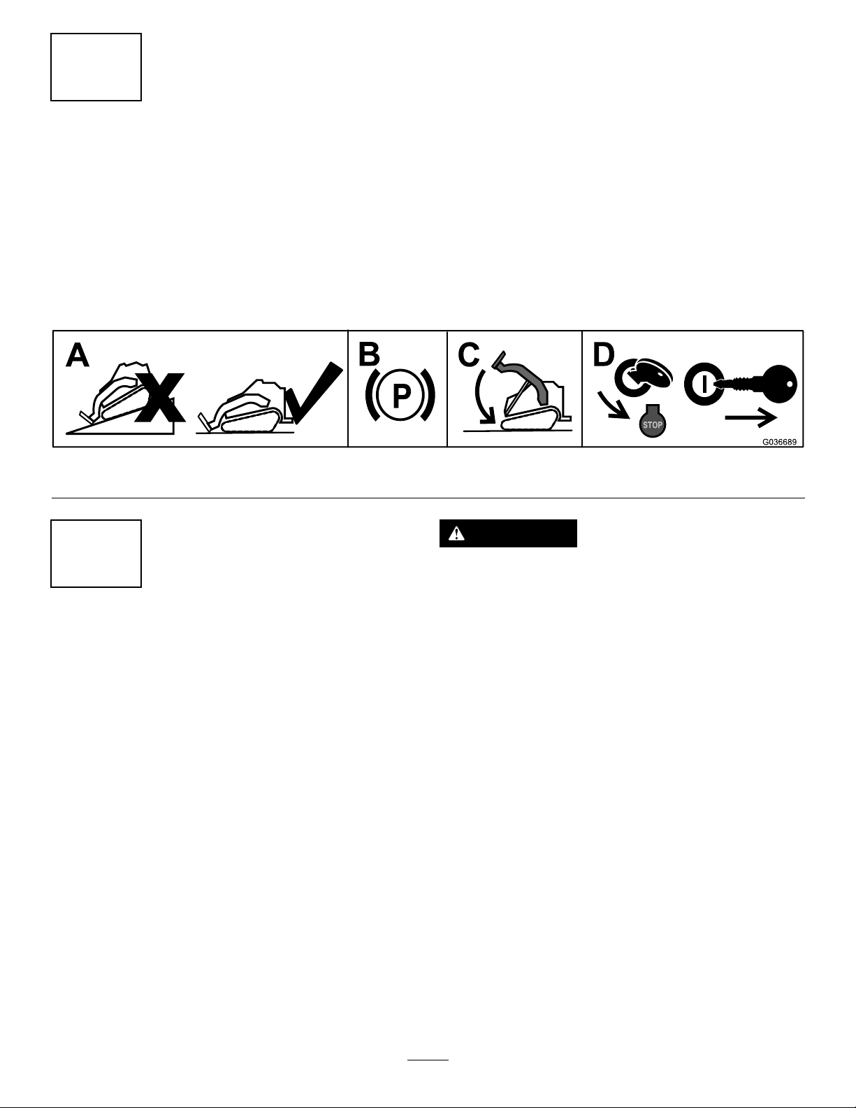
1.Movethemachinetoalevelsurface.
2.Engagetheparkingbrake.
3.Lowertheloaderarms.
4.Shutofftheengineandremovethekey .
g036689
Figure1
2
DisconnectingtheBattery
NoPartsRequired
Procedure
1.Openthehoodandsecurethehoodprop.
2.Disconnectthebattery.
•Ifthemachinehasabattery-disconnectswitch,
turntheswitchtotheOFFposition;refertothe
Operator’sManualforthemachine.
•Ifthemachinedoesnothaveabattery-disconnect
switch,removethenegativebatterycablefromthe
battery.
WARNING
Incorrectbatterycableroutingcoulddamagethe
machineandcablescausingsparks.Sparkscan
causethebatterygassestoexplode,resultingin
personalinjury.
•Alwaysdisconnectthenegative(black)battery
cablebeforedisconnectingthepositive(red)
cable.
•Alwaysconnectthepositive(red)batterycable
beforeconnectingthenegative(black)cable.
3
Page 4
3
RemovingtheExistingHoses
NoPartsRequired
Procedure
Determinetheleftandrightsidesofthemachinefromthe
normaloperatingposition.
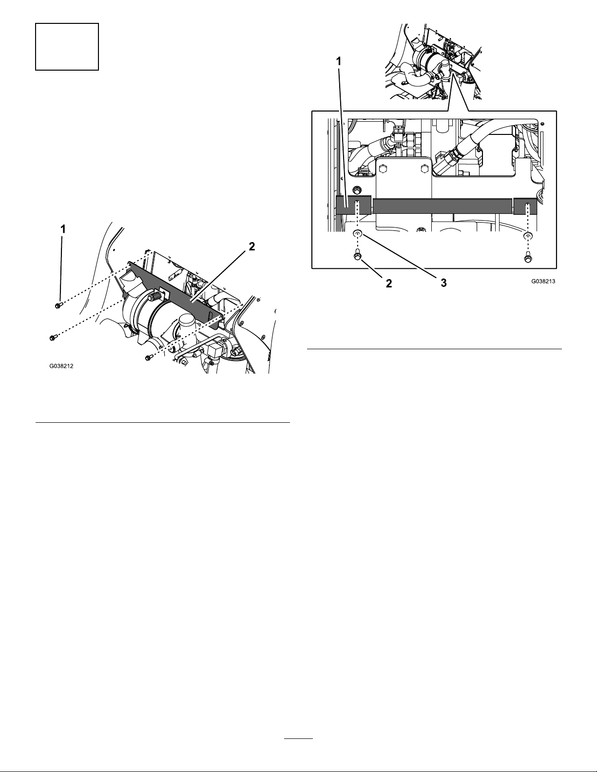
1.Removethe3bolts(1/4x3/4inch)securingthecover
plateandremovethecoverplate(Figure2).
g038213
Figure3
1.Rubberbafe3.Washer(1/4inch)
2.Bolt(1/4x3/4inch)
Figure2
1.Bolt(1/4x3/4inch)2.Coverplate
2.Removethe2bolts(1/4x3/4inch)and2washers
(1/4inch)securingtherubberbafeandlowerthe
bafe(Figure3).
g038212
4
Page 5
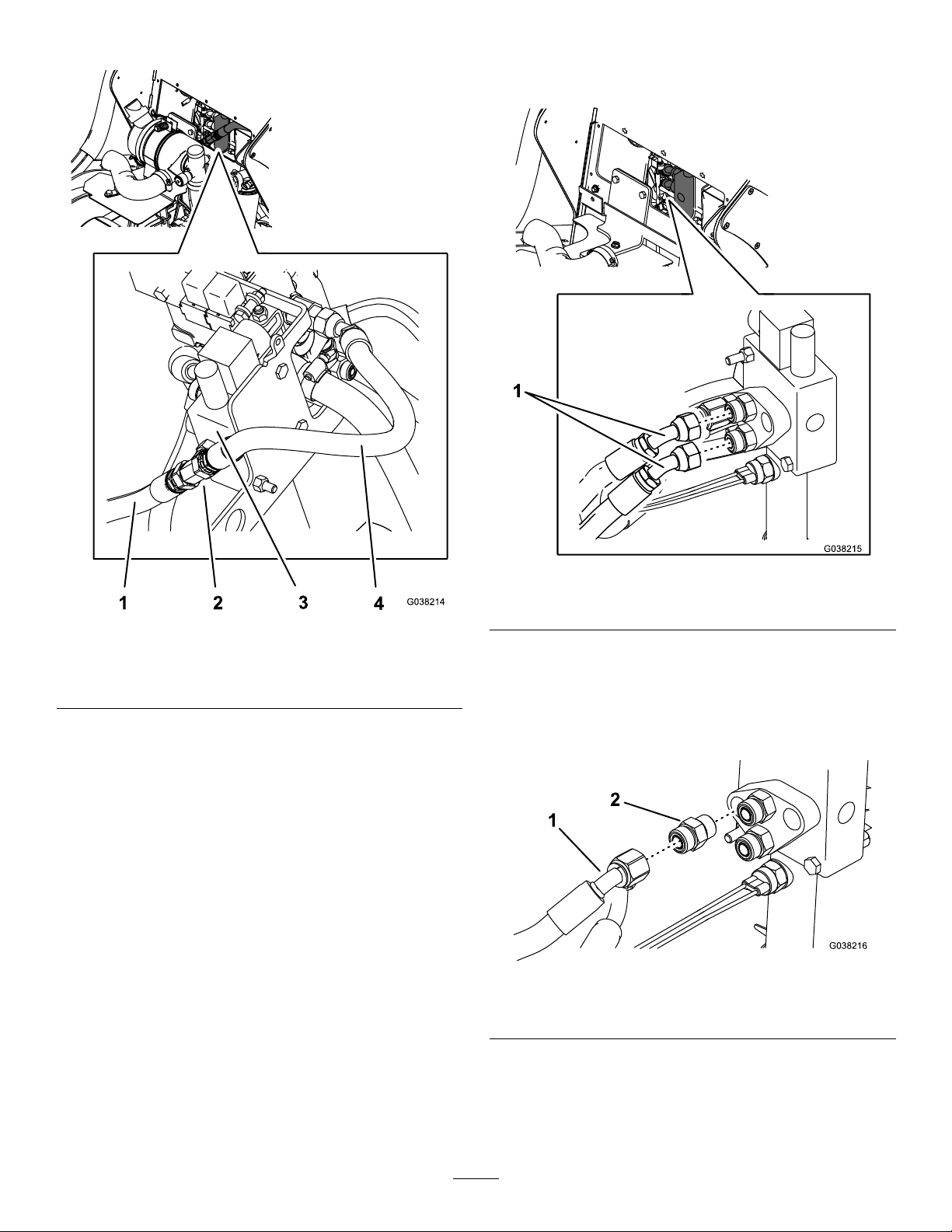
3.RemoveanddiscardtheshorthoseshowninFigure4.
5.MarkthehosesshowninFigure5withtheir
correspondingportlocationssothatyoucaninstall
themintothecorrectportslater.
Figure4
1.Longhose3.Auxiliaryvalve
2.Teetting4.Shorthose
4.Disconnectthelonghosefromtheteettingand
removetheteetting(Figure4).
g038215
Figure5
g038214
1.Markanddisconnectthesehoses.
6.Disconnectthe2hosesfromthettingsintheauxiliary
valve(Figure5).
7.Removetheremaininghosefromtheauxiliaryvalve
andtheloaderarmvalve.Discardthehoseandttings
(Figure6).
g038216
Figure6
1.Remaininghose2.Fitting
5
Page 6
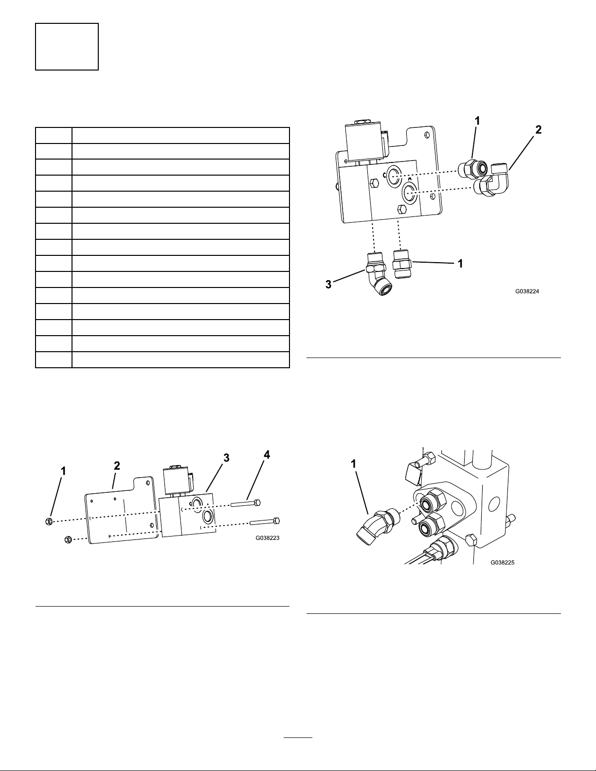
2.Installa90-degreettingintothevalveassembly
(Figure8).
4
InstallingtheValveAssembly
Partsneededforthisprocedure:
1
Low-owvalve
1Bracket
2
Bolt(1/4x2-1/2inches)
2
Locknut(1/4inch)
2
Straighttting
2
45-degreetting
2
90-degreetting
1U-shapedtube
1
Loaderarmtting
1Teetube
190-degreetube
1
Curvedtube
1Hydraulichose
1Hoseprotector
3
Cabletie
3.Install2straightttings,anda45-degreettingtothe
valveassembly(Figure8).
Note:Ensurethatthettingsareorientedinthesame
directionasFigure8.
g038224
Figure8
1.Straighttting3.45-degreetting
2.90-degreetting
4.Torquethettingsto79to98N∙m(58to72ft-lb).
Procedure
1.Installthelow-owvalvetothebracketusing2bolts
(1/4x2-1/2inches)and2locknuts(1/4inch)as
showninFigure7.
Figure7
1.Nut(1/4inch)3.Low-owvalve
2.Bracket
4.Bolt(1/4x2-1/2inches)
5.Installa45-degreettingtotheauxiliaryvalveinthe
locationofthettingthatyoudiscardedpreviously
(Figure9).
Note:Donottorquethettingatthistime.
g038223
g038225
Figure9
1.45-degreetting
6
Page 7
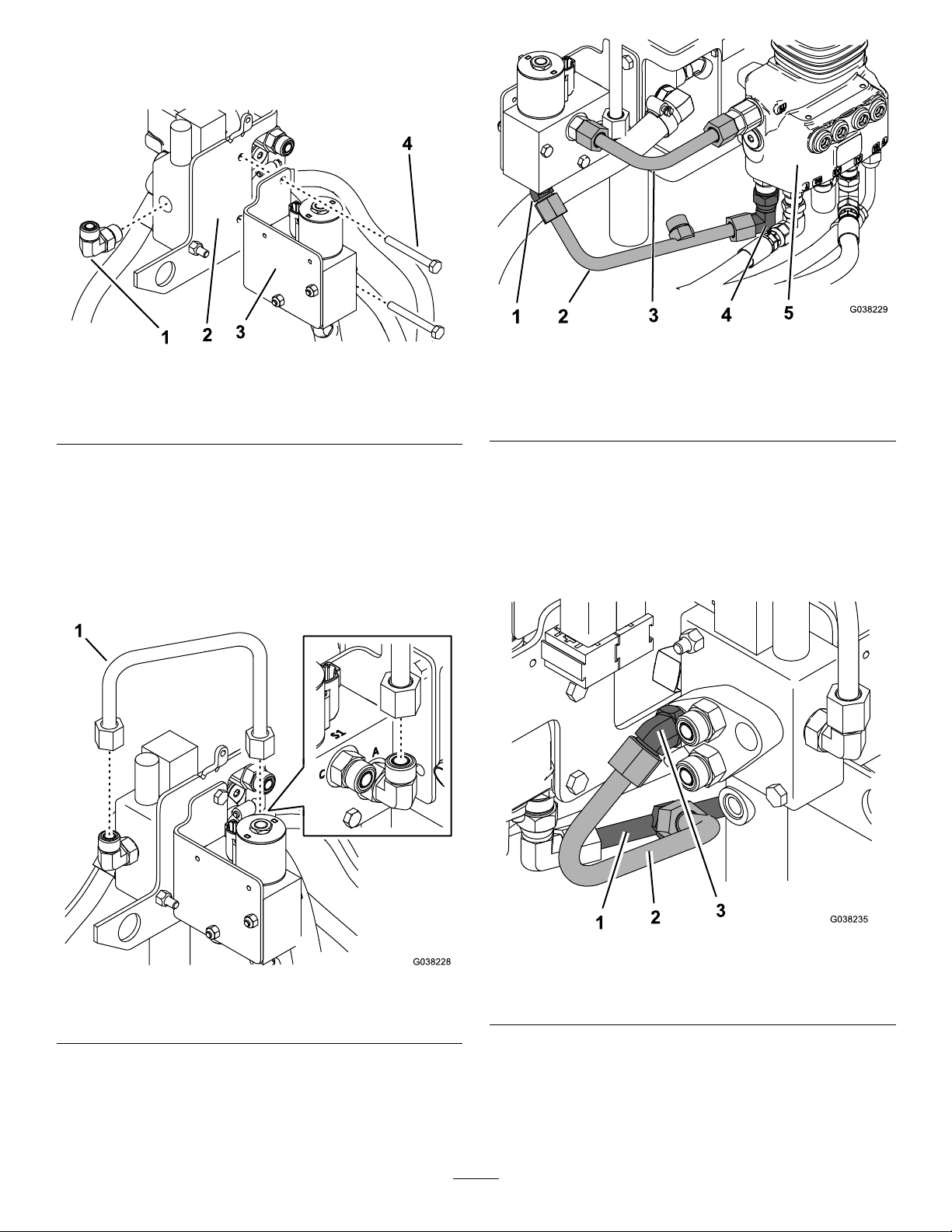
6.Removethe2rearboltssecuringtheauxiliaryvalveto
thebracketandusethemtomountthelow-owvalve
assembly(Figure10).
Figure10
1.90-degreetting3.Low-owvalveassembly
2.Bracket
4.Bolt(5/16x2-3/4inches)
g038229
g194743
1.45-degreetting4.Loader-armtting
2.Teetube5.Loader-armvalve
3.90-degreetube
Figure12
7.Installa90-degreettingtothelocationwhereyou
previouslyremovedtheteetting(Figure10).
8.InstalltheU-shapedtubetothe90-degreettingand
tothettinginPortAinthelow-owvalveassembly
(Figure11).
Note:Donottorquethenutsonthetubeuntilall
tubesareinplace.
10.Connecttheteetubetotheloader-armttingandthe
45-degreettinginthelow-owvalve(Figure12).
11.Connectthe90-degreetubetothettingsinthe
low-owvalveandloader-armvalve(Figure12).
12.Connectthecurvedtubetotheteetubeandthe
45-degreettingthatinstalledinstep5(Figure13).
Figure11
1.U-shapedtube
9.Installtheloader-armttingtotheloader-armvalve
(Figure12).
g038235
Figure13
g038228
1.Teetube
2.Curvedtube
3.45-degreetting
13.Torquethenutsonthe4tubesthatyoujustinstalledto
50to64N∙m(37to47ft-lb).
14.Torquethe90-degreettingthatyouinstalledinstep7
andtheloader-armttingthatyouinstalledinstep9to
79to98N∙m(58to72ft-lb)
7
Page 8
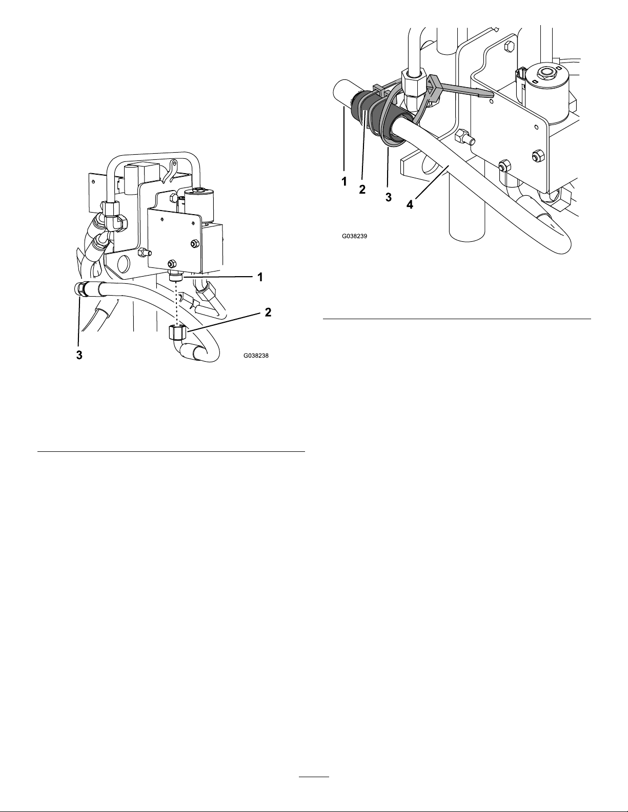
15.Connectthehosesthatyouremovedinstep6of
3RemovingtheExistingHoses(page4)totheir
correspondingportsandtorquethemto50to64N∙m
(37to47ft-lb).
16.Connectthehydraulichosetothestraighttting
beneaththelow-owvalveandtothelonghosethat
youdisconnectedfromtheteettinginstep4of3
RemovingtheExistingHoses(page4)asshownin
Figure14.
g038239
Figure15
Figure14
1.Straighttting3.Connectthisendtothe
longhose.
2.Connectthisendtothe
straighttting.
17.Torquethehosettingsto50to64N∙m(37to47ft-lb).
18.Covertheconnectionbetweenthe2hosesusingthe
hoseprotectorand2cableties(Figure15).
1.Longhose
2.Hoseprotector4.Kithydraulichose
3.Cabletie
19.Useanothercabletietosecuretheprotectorandhoses
totheelbowadapter(Figure15).
g038238
8
Page 9
5
InstallingtheSwitchandWire Harness
Partsneededforthisprocedure:
1
Switch
1Decal
1Wireharness
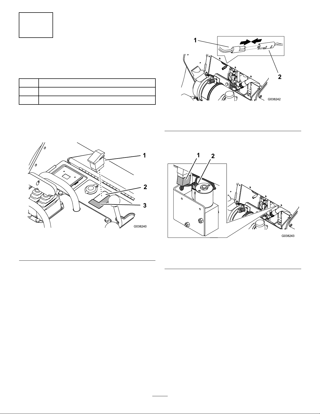
3.Unplugthecapfromtheauxiliaryconnectoronthe
machinewireharnessandconnectthekitwireharness
totheconnector(Figure17).
g038242
Figure17
Procedure
1.Removetheplugfromtheconsoleandinstallthe
switch(Figure16).
Figure16
1.Switch
2.Plug
2.Ifthedecalontheconsoledoesnotshowtherabbit
andturtlesymbolsneartheswitch,afxthekitdecal
(Figure16).
3.Decal
1.Kitwireharnessconnector2.Auxiliaryconnectoron
machinewireharness
4.Connectthekitwireharnesstotheswitchandthe
low-owvalve(Figure18).
g038240
g038243
Figure18
1.Connecttotheswitch2.Connecttothelow-ow
valve
5.Installtherubberbafe(seeFigure3).
6.Installthecoverplate(seeFigure2).
7.Ifthemachinehasabattery-disconnectswitch,turn
theswitchtotheONposition.Ifthemachinedoesnot
haveabattery-disconnectswitch,connectthenegative
batterycabletothebattery.
8.Closethehood.
9
Page 10

Notes:
Page 11

Notes:
Page 12

 Loading...