

Page 1
Seeder Box Kit
Dingo Soil Cultivator
Form No. 3326-614
Model No. 23120
Loose Parts
Note: Use the chart below to identify parts for assembly.
Description Qty. Use
Seeder box
Wheel handle
Nut, M8
Lever handle
Bolt, small
Mounting bracket, right hand
Mounting bracket, left hand
Bolt, M10 x 35 mm
Locknut, M10
Bolt, M12 x 60 mm
Locknut, M12
1
1
1
1
1
1
1
8
8
2
2
Installing the wheel handle
Installing the lever handle
Installing the Seeder Box
Installation
Instructions
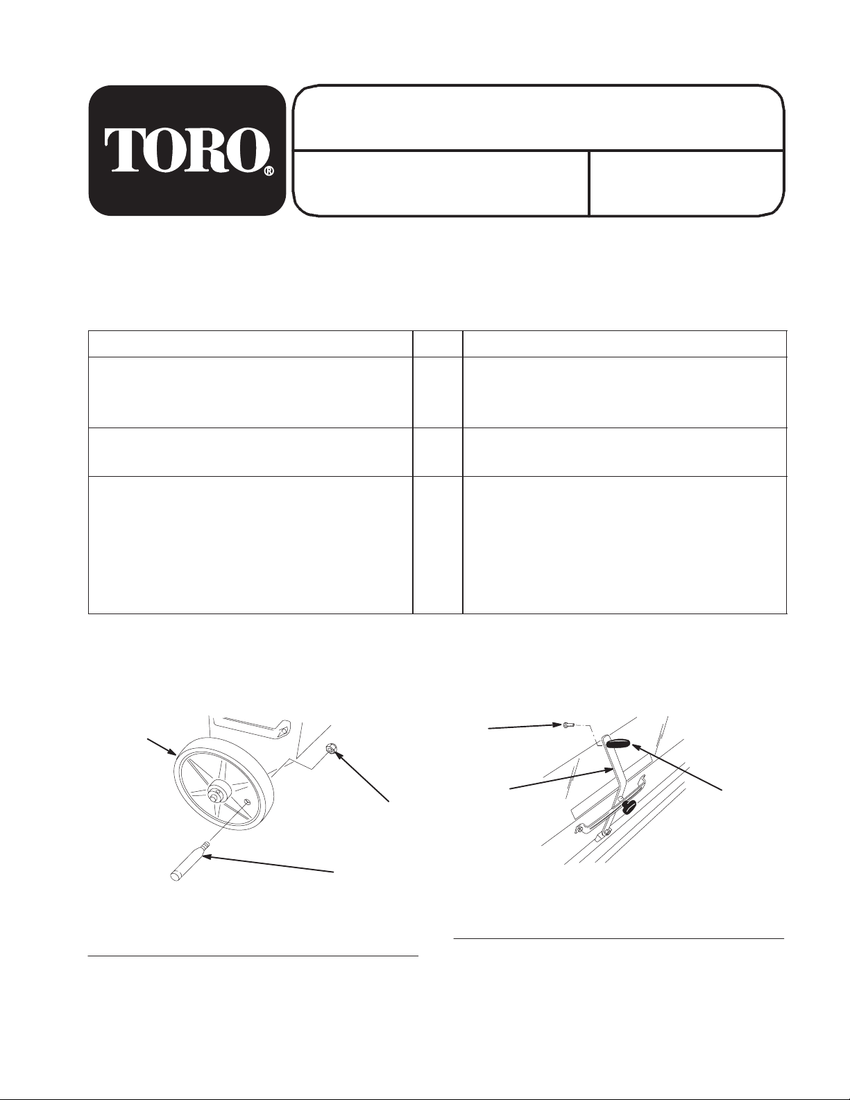
Installing the Wheel Handle
Insert the stud on the handle through the wheel and secure
in with a nut (M8) (Fig. 1).
1
3
1. Wheel
2. Handle
2
Figure 1
3. Nut
m–5363
Installing the Lever Handle
Install the lever handle to the lever on the front of the
seeder box using the small bolt (Fig. 2).
3
1
1. Lever
2. Lever handle
Figure 2
3. Small bolt
2
m–5364
Page 2
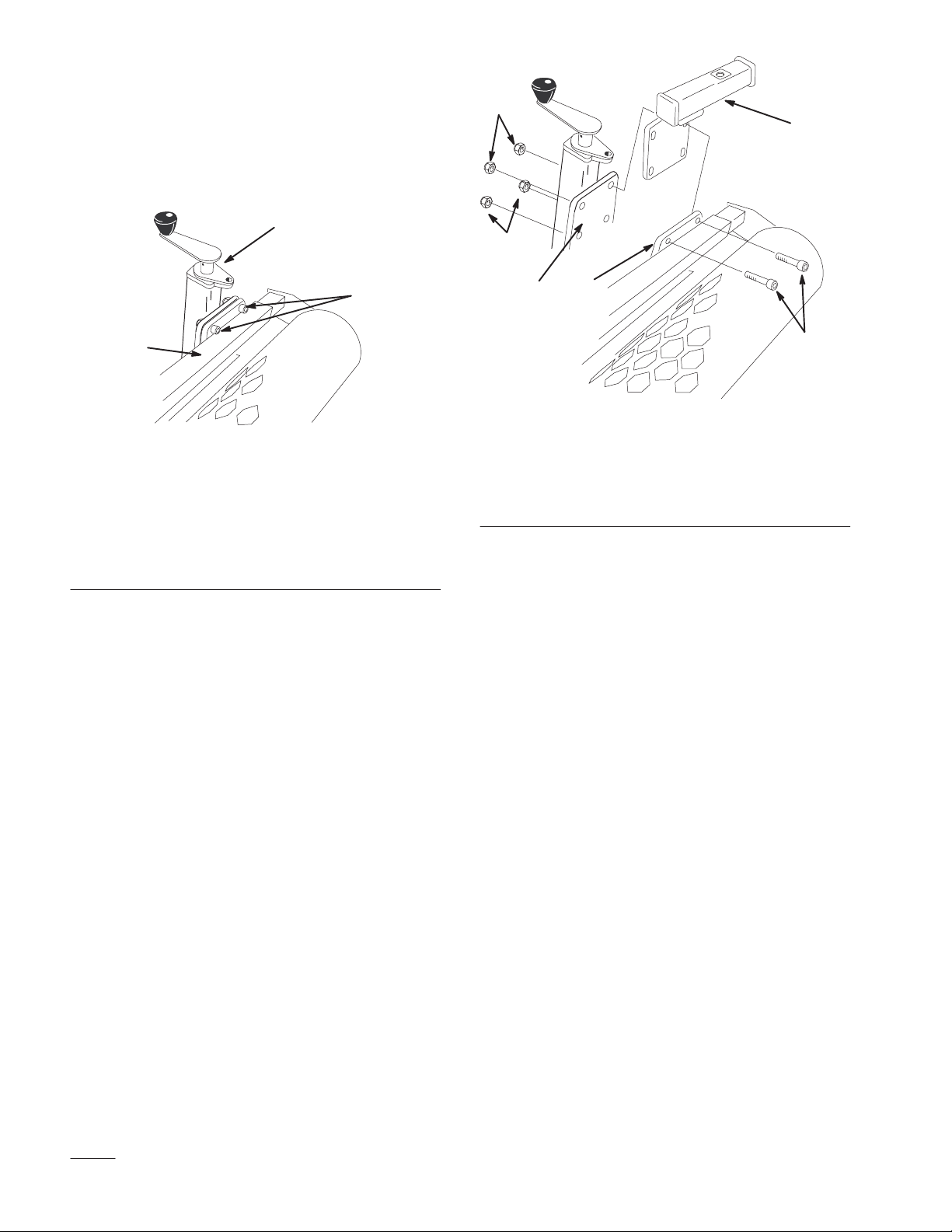
Installing the Mounting
Brackets
1. Loosen the 8 bolts and nuts securing the scraper to the
soil cultivator (Fig. 3).
Note: There are 4 bolts on each side of the scraper,
directly under the scraper adjustment cranks.
1
2
3
m–5365
Figure 3
(Only the left side of the cultivator is illustrated)
1. Left side, scraper
adjustment crank
2. Bolts securing the scraper
(2 additional bolts not
shown secure the scraper
beneath the roller bar)
2. Remove and discard 4 bolts and nuts from one side of
the scraper (Fig. 3).
3. Remove the brackets and fasteners from the seeder box
mounting pockets (Fig. 5).
3. Roller bar
5
1
5
2
3
4
m–5368
Figure 4
(Only the left side of the cultivator is illustrated)
1. Mounting bracket
2. Scraper mounting plate
3. Cultivator mounting plate
4. Bolt, M10 x 35 mm
5. Locknut, M10
5. Slide the 4 bolts (M10 x 35 mm) through the cultivator
mounting plate, bracket, and scraper mounting plate,
capping them with 4 locknuts (M10) (Fig. 4). Do not
tighten them.
6. Repeat steps 2 through 5 for the other side of the
scraper.
4. Slide the appropriate mounting bracket between the
scraper mounting plate and the cultivator mounting
plate on one side of the cultivator (Fig. 4).
Note: The brackets should extend toward the outside
of the machine.
2
Page 3

7. Install the seeder box over the brackets (Fig. 5).
3
1
Adjusting the Seed Drop Rate
1. Loosen the knob on the front of the adjustment lever
assembly on the front of the seeder box (Fig. 6).
4
2
4
m–5369
Figure 5
(Only the left side of the seeder box is illustrated)
1. Seeder box mounting
pocket
2. Mounting bracket
3. Bolt, M12 x 60
4. Locknut, M12
8. Secure the seeder box to the mounting brackets using 2
bolts (M12 x 60) and locknuts (M12) (Fig. 5).
9. Torque the 2 bolts and locknuts 59 to 73 ft.-lb. (80 to
100 N⋅m).
10.Torque the 8 bolts and locknuts securing the mounting
brackets and scraper to 34 to 42 ft.-lb. (47 to 57 N⋅m).
Removing the Seeder Box
Remove the 2 bolts and locknuts securing the seeder box
to the mounting brackets and remove the box.
Leave the mounting brackets installed on the cultivator for
future uses of the seeder box.
3
1
2
m–5370
Figure 6
1. Adjustment lever
2. Knob
3. Decrease flow rate
4. Increase flow rate
2. Slide the lever to the desired setting (Fig. 6).
The seeder box is labeled with settings from 0 to 20. 0
indicates that no seed will drop; 20 is a drop rate of
approximately 12.5 lb. of grass seed per 1000 sq. ft. of
ground (61 Kg per 1000 m2). You may need to
experiment to obtain the seed drop rate that suits your
needs.
Important Only use the seeder box to dispense
lawn seeds, such as grasses. Larger seeds may clog the
seeder box.
3. Tighten the knob (Fig. 6).
3
Page 4

 Loading...