

Page 1

Trailer
TRXTrencher
ModelNo.22979
ModelNo.22979HD
FormNo.3378-761RevB
SetupInstructions
Safety
Readandunderstandthefollowingbeforeusingthetrailer:
•Beforeeveryuse:
–Inspectthecoupler,ballandhitch.
–Alwaysusesafetychains.
–Verifyalllightsarefunctioningproperly.
–Verifythetiresareproperlyinatedasrecommended
ontires.
–Verifylugnutsaretightandtorquedproperly.
–Machineisproperlysecured.
•Knowhowtoproperlycontrolyourtowingvehicle/trailer
combinationonthehighwayunderallconditions.
Remembertheloadedweightofthetrailerwillincrease
yourbrakingandstoppingdistancesappreciably.
Safetydecalsandinstructionsareeasilyvisibletotheoperatorandarelocatednearanyareaofpotential
danger.Replaceanydecalthatisdamagedorlost.
•Youareresponsiblefordeterminingthetowingcapacity
ofyourvehicle.
•Cleanoffmachinespriortoloadingontothetrailer.Keep
trailercleanofloosedebristhatcouldfalloffduring
transportcausingahazard.
•Useproperloadingandunloadingproceduresand
sequences.Readmanualsandfollowinstructions
provided.
•Inspectthetrailerandmachineoftenduringtransport.
SafetyandInstructional
Decals
©2013—TheToro®Company
8111LyndaleAvenueSouth
Bloomington,MN55420
115–4883
Registeratwww.T oro.com.
OriginalInstructions(EN)
PrintedintheUSA.
AllRightsReserved
*3378-761*B
Page 2
Setup
LooseParts
Usethechartbelowtoverifythatallpartshavebeenshipped.
ProcedureDescription
1
2
3
4
5
Trailerbed1
Wheel2
Lugnuts10
Tongue1
Bolts(5/8x3inches)
Nuts(5/8inch)
Mountingstrap2
Jack1
Bolt4
Locknut4
Chain
Ramp1
Bolt(1/2x1-1/2inches)
Nut(1/2inch)
Rampstrap2
Cotterpin(1-1/4inch)
Nopartsrequired
Qty.
Use
Installthewheels.
2
2
1
2
2
2
–
Attachthetongue.
Installthetrailerjack.
Installtheramp.
Testthewiringharness
1
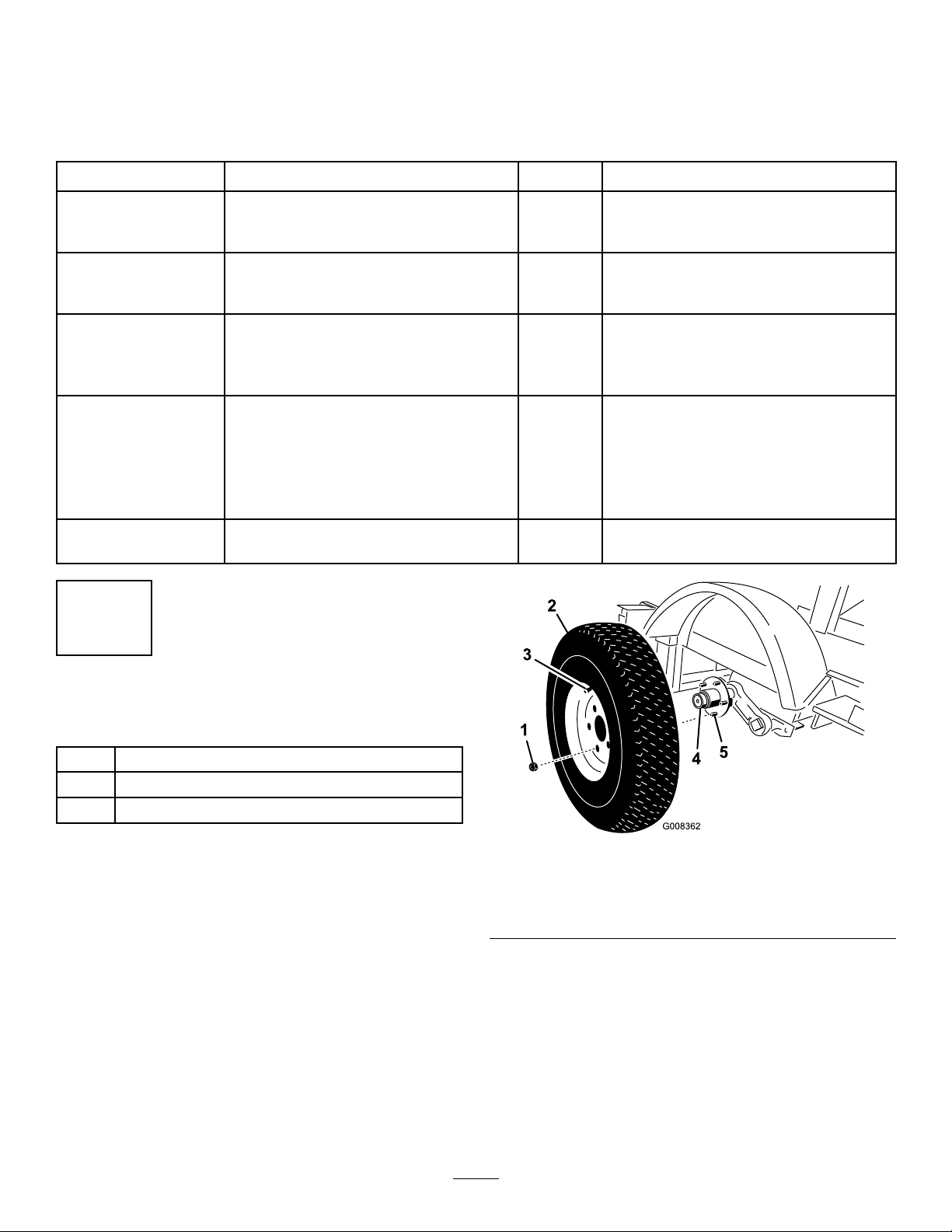
InstallingtheWheels
Partsneededforthisprocedure:
1Trailerbed
2Wheel
10Lugnuts
Procedure
1.Usingahoist,ormechanicaljack,raisethetrailerbed
toallowthewheelstobeinstalled.
2.Installthewheelsontothehubwiththevalvestem
facingouttoallowaccess(
Figure1).
Figure1
1.Lugnut4.Hub
2.Wheel5.Posts
3.Valvestem
3.Secureeachwheeltothehubusing5lugnuts.Torque
thenutsto50-75ft-lb(68-102N-m).
4.Whilethebedisstillraisedremovethefasteners
securingthepackingstandstothetrailerbed.
5.Lowerthebedtothegroundandverifythecold
pressureatthetiresisatamaximumof80psi.
2
Page 3
2
AttachingtheTongue
Partsneededforthisprocedure:
1Tongue
2
Bolts(5/8x3inches)
2
Nuts(5/8inch)
Procedure
1.Laythetongueoutinfrontofthetrailerandlocatea
exiblewirelongerthanthetongue.
2.Feedthewirethroughthelengthofthetonguesoa
portionofthewireisvisibleatbothends(
Figure2).
Figure3
1.Tongue3.Wiringharness
2.Opening
5.Useajackorhoist,raisethefrontendofthetrailerbed
toallowtheinstallationofthetongue(Figure4).
4.Wire,securedtoharness
Figure2
1.Tongue4.Tongue,trailerside
2.Opening5.Harness,fromtrailer
3.Wire
3.Removethefastenersecuringthehitchwiringbundled
tothetrailerbed.
4.Securethewireinthetonguetothewiringharness
onthetrailerandpullthewiringharnessthroughthe
lengthofthetongueusingthewire(Figure3).Remove
thewirefromtheharness.
Figure4
1.Jack2.Trailer
6.Movethetongueintopositionunderthetrailerbed
andraiseittoaligntherearholesinthetrailerbedwith
therearholesintongue.
7.Withthehelpofanotherperson,installabolt(5/8x3
inches)throughtheholes.Raisethefrontendofthe
tonguetoalignthefrontholesanduseabolt(5/8x3
inches)toholdthetongueinplace(Figure5).
Figure5
1.Trailer,underside4.Electricalharness
2.Tongue
3.Boltholes
3
5.Bolt(5/8x3inches)
Page 4

8.Atthefrontendofthetongue,pullthewiringharness
forwardtoremoveallslackintheharnessbefore
continuingtheinstallation.
Important:Makesurethewiringharnessisnot
beingpinchedorimpingedduringtheinstallation.
Damagedwirescancausethetaillightsto
malfunction.
9.Securetheboltswith2nuts(5/8inch)(Figure6).
Torquethenutsto76-100ft-lb(103-135N-m).
3
InstallingtheTrailerJack (Model22979)
Partsneededforthisprocedure:
2Mountingstrap
1Jack
4Bolt
4Locknut
Procedure
1.Placethejackagainstthetongue(Figure7).
Figure6
1.Trailerandtongue
2.Bolt(5/8x3inches)
10.Lowerthefrontendofthetrailer.
3.Nut(5/8inch)
Figure7
1.Locknuts(4)3.Bolts(4)
2.Mountingstraps
2.Positionthe2mountingstrapsontheothersideof
thetongue(Figure7).
3.Securethejackandthe2mountingstrapstothetongue
using4boltsand4locknuts(Figure7).
4.Torquethelocknutsto33.9N-m(25ft-lbs).
4
Page 5

4
InstallingtheRamp
Partsneededforthisprocedure:
1
Chain
1Ramp
2
Bolt(1/2x1-1/2inches)
2
Nut(1/2inch)
2Rampstrap
2
Cotterpin(1-1/4inch)
Procedure
1.Installtheretainingchainfromthebedofthetrailerto
theretainingpin(Figure8).
Figure8
1.Trailerbed4.Retainingpin
2.Loop5.Keeper,attached
3.Chain
2.Withthehelpofanotherperson,placetherampinto
positionattheendofthetrailerbed.Useabolt(1/2x
1-1/2inches)andnut(1/2inch)ateachhingetoattach
theramptothetrailerbed(Figure9).
Figure9
1.Trailerbed
2.Ramp
3.Bolt(1/2x1-1/2inches)
3.Tightentheboltuntilthereisapproximatelya1/16
inchofgapbetweenthebedandramphinges.Thiswill
allowtheramptomovefreelywhilesecurelyfastened
tothetrailer.
Important:Donotovertightentheramppivot
boltsorbindingwilloccurcausingdamagetothe
trailer.
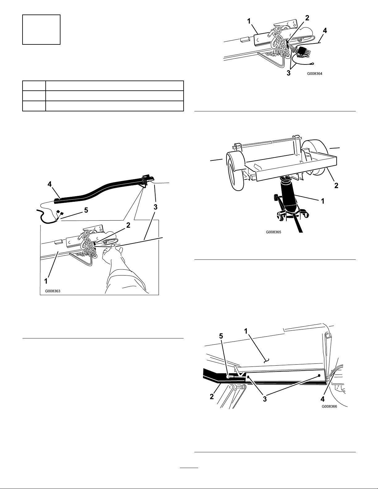
4.Installarampstraptoeachsideofthetrailerasshown
in
Figure10.Installacotterpinandbendbackthe
endstosecurethestrapstothetrailer.
4.Nut(1/2inch)
5.1/16inchgap
5
Page 6

Figure10
1.Lynchpin4.Ramp
2.Postonramp5.Postonbed
3.Rampstrap
5.Raisetherampandusethestrapsandlynchpinsto
secureitinthetransportposition(Figure10).
6.Cotterpin
5
TestingtheWiringHarness
NoPartsRequired
Procedure
1.Locatethewhitegroundwireonthewiringharness
andgroundboltonthefrontofthetongue.Secure
thegroundwiretothetongueatthegroundbolt.Do
notovertighten.
Figure11
1.Tongue3.Wiringharness
2.Holster
Operation
OperatingtheJack
Turnthecrankclockwisetolowerthejack(Figure12).
2.Plugtheatconnectortoasuitablevehiclefortesting.
Checktomakesurethebrakelightsilluminateproperly
withthebrakepedalappliedandthetaillightsash
whentheturningsignalsareuse.
3.Disconnectthewireconnectorandbundleittothe
trailer.Storetheatconnectortotheholsteronthe
tongue(
Figure11).
Figure12
Turnthecrankcounterclockwisetoraisethejack(Figure13).
6
Page 7

Figure15
1.Tongue4.Auxiliarychains
2.Ballsocket
3.Handle,lockedposition
5.Lockingpin(notincluded
withthetrailer)
Figure13
Pulloutonthehandletorotatethejack(Figure14).
Figure14
4.Closethecouplerlatchmakingsureitissecurelylocked.
5.Installapin(notincludedwiththetrailer)tolockthe
couplerlever.
6.Attachthechainstoholesonthehitch.Connectthe
wiringharnesstotheatconnectoronthehitch.
LoadingtheTrencher
CAUTION
Attemptingtoloadorunloadthemachinefrom
atrailerthatisnotsecurelyhitchedtoasuitable
vehiclecouldcausethetrailertobecomeunstable,
andtipcausinginjurytoyouorbystanders.
Makesurethetrailerissecurelyhitchedtoasuitable
vehicleparkedonalevelsurfacebeforeattempting
toloadorunloadthemachine.
1.Removetheretainingstrapsandlowertherampto
theground.
2.Removethetiedownbarpinandslidethebarsapart
(Figure16).
1.Handle
AttachingtheTrailer
Thistrailerusescouplersthatrequirea2inchballforthe
hitch.
1.Rotatethejackintothehorizontalposition(Figure14).
2.Raisethetrailertoasuitablehitch.
3.Lifttheleveronthetonguewhileloweringthecover
overtheballhitch(Figure15).
Important:Allowthepinandchaintolayonthe
centerofthebedtoavoidrunningoveritwiththe
machineanddamagingit.
7
Page 8

Figure16
UnloadingtheTrencher
CAUTION
Attemptingtoloadorunloadthemachinefrom
atrailerthatisnotsecurelyhitchedtoasuitable
vehiclecouldcausethetrailertobecomeunstable,
andtipcausinginjurytoyouorbystanders.
Makesurethetrailerissecurelyhitchedtoasuitable
vehicleparkedonalevelsurfacebeforeattempting
toloadorunloadthemachine.
1.Removelynchpinssecuringtherampstraps.Remove
thestrapsandslowlylowertheramptotheground.
1.Tiedownbar2.Retainingpin
3.Startthetrencheraccordingtothedirectionsinthe
Operator'sManualandruntheengineatlowspeed.
4.Withthetrencherarmraisedinthetransportposition
drivethemachineuptherampontothetrailerbed.
5.Takecaretoloadthetrencherwiththetracksbetween
guiderailsonthetrailerbed(Figure17).Movethe
trencherforwardslowlyuntilthefrontofthemachine
meetstheforwardstoponthetrailerbed.
Figure17
1.Forwardstop
2.Guiderails
DANGER
Therampinthetransportpositionrepresents
astoredenergyhazardandifnotsecuredcan
fall;injuringyouorbystanders.
Holdtherampinplacewhenremovingstraps
andusecaretolowertherampcarefullytothe
ground.
2.Removethepinontheholddownbarandlaythechain
andpinonthecenterofthetrailerbed.Slidethehold
downbarsapart.
3.StartthemachineaccordingtotheOperator'sManual
anddisengagetheparkingbrake.
4.Raisethetrencherarmintothetransportposition.
5.Slowly,whilelookingbehindyouanddown,movethe
machinedownandofftheramp.
RemovingtheTrailerHitch
1.Disconnectthewiringharnessfromtheelectrical
connectoronthehitch.Placetheconnectorintothe
holsteronthetongue.
2.Removethechainsretainingthetonguetothehitch.
3.Removethepinandlifttheleverontopofthehitch.
6.Turnthemachineoffandengagetheparkingbrake.
Lowerthetrencherarmuntilitrestsonthefrontstop.
Makesurethefrontcrosstubeofthetrencherisfully
engagedtothefrontstoponthetrailer.
7.Slidethetiedownbarstogetherthroughthereartie
downloops,aligningtheholestoallowfortheretaining
pin.Installthepin.
8.Raisetherampandusethestrapsandlynchpinsto
secureitinthetransportposition.
4.Withthetongueleverraise,liftthetongueupandoff
thetrailerhitch.
5.Takecareandslowlylowerthetonguetotheground.
Replacethepininthetonguelever.
Maintenance
CheckingLugNuts
ServiceInterval:Aftertherst10hours/Monthly
(whichevercomesrst)
Torquethenutsto68-102N-m(50-75ft-lb).
8
 Loading...