

Page 1
FormNo.3362-871RevA
BoreDriveAttachment
forTRXTrenchers
ModelNo.22978—SerialNo.310000001andUp
ToregisteryourproductordownloadanOperator'sManualorPartsCatalogatnocharge,gotowww.T oro.com.OriginalInstructions(EN)
Page 2
Theremaybeburiedpower,gas,and/or
telephonelinesintheworkarea.Shockor
explosionmayoccurifyoudigintothem.
Havethepropertyorworkareamarkedfor
buriedlinesanddonotdiginmarkedareas.
Contactyourlocalmarkingserviceorutility
companytohavethepropertymarked(for
example,intheUnitedStates,call811forthe
nationwidemarkingservice).
Figure1
1.Safetyalertsymbol
Thismanualalsouses2wordstohighlightinformation.
Importantcallsattentiontospecialmechanical
informationandNoteemphasizesgeneralinformation
worthyofspecialattention.
ThisproductcomplieswithallrelevantEuropean
directives,fordetailspleaseseetheseparateproduct
specicDeclarationofConformity(DOC)sheet.
Introduction
ThismachineisanattachmentforaTRXtrencher
intendedforusebylandscapeprofessionalsandrental
equipmentoperators.Itisdesignedforboringholes
throughsoilunderdrivesandsidewalksandforpulling
cablingandpipingthroughtheboredholes.Itisnot
designedforboringthroughrockorothernon-soil
debris.
Readthisinformationcarefullytolearnhowtooperate
andmaintainyourproductproperlyandtoavoidinjury
andproductdamage.Youareresponsibleforoperating
theproductproperlyandsafely.
YoumaycontactTorodirectlyatwww .T oro.comfor
productandaccessoryinformation,helpndinga
dealer,ortoregisteryourproduct.
Contents
Introduction.................................................................2
Safety...........................................................................3
SafetyandInstructionalDecals.............................3
Setup............................................................................4
1DisconnectingtheExistingHydraulic
Hoses...............................................................4
2InstallingtheHydraulicManifold.......................6
3ConnectingtheHydraulicHoses........................7
4AssemblingtheControlPanel............................8
5AssemblingtheRodGuide.................................8
ProductOverview........................................................9
Specications.......................................................9
Attachments/Accessories.....................................9
Operation.....................................................................9
ConnectingtheDriveHeadtothe
Trencher...........................................................9
InstallingAccessories.........................................10
RemovinganAccessory......................................10
BoringaHole.....................................................10
Storage.......................................................................12
Wheneveryouneedservice,genuineToroparts,or
additionalinformation,contactanAuthorizedService
DealerorToroCustomerServiceandhavethemodel
andserialnumbersofyourproductready.Themodel
andserialnumbersareprintedonaplatelocatedonthe
rightsideofthedrivehead.Writethenumbersinthe
spaceprovided.
ModelNo.
SerialNo.
Thismanualidentiespotentialhazardsandhas
safetymessagesidentiedbythesafetyalertsymbol
(Figure1),whichsignalsahazardthatmaycauseserious
injuryordeathifyoudonotfollowtherecommended
precautions.
©2009—TheT oro®Company
8111LyndaleAvenueSouth
Bloomington,MN55420
Contactusatwww.T oro.com.
2
PrintedintheUSA.
AllRightsReserved
Page 3
Safety
Improperuseormaintenancebytheoperatoror
ownercanresultininjury.Toreducethepotential
forinjury,complywiththesesafetyinstructionsand
thoseinthetractionunit
payattentiontothesafetyalertsymbol,which
means
Caution
,
W ar ning
safetyinstruction.Failuretocomplywiththe
instructionmayresultinpersonalinjuryordeath.
•Theremaybeburiedpower,gas,and/ortelephone
linesintheworkarea.Shockorexplosionmayoccur
ifyoudigintothem.
Havethepropertyorworkareamarkedforburied
linesanddonotdiginmarkedareas.Contactyour
localmarkingserviceorutilitycompanytohavethe
propertymarked(forexample,intheUnitedStates,
call811forthenationwidemarkingservice).
•Rotatingrodandbitscanentanglelooseclothing,
hands,arms,legs,andfeet,causingdeathorserious
injury.
Operator’ s Man ual
,or
Danger
—personal
.Always
•Alwaysuse2peopletooperatetheattachment,one
tooperatethetractionunitandtheothertoguide
theboringunitwiththeguidetool.
•Lightningcancausesevereinjuryordeath.If
lightningisseenorthunderisheardinthearea,do
notoperatethemachine;seekshelter.
SafetyandInstructional
Decals
Safetydecalsandinstructionsareeasily
visibletotheoperatorandarelocated
nearanyareaofpotentialdanger.
Replaceanydecalthatisdamagedor
lost.
–Keepatleasttenfeetfromrotatingparts,unless
youareoperatingtherodguidetool.
–Neveruseanythingbuttherodguidetoolfor
startingtherodandboringbit.
–Keepextremitiesandotherpartsofyourbodyor
clothingawayfromrotatingparts.
–Neverstraddleorstandontherodwhenthe
engineisrunning.
–Donotwearlooseclothingorjewelrywhile
operatingorassistingwiththeboringunit.
–Usecautionwhenstandingnexttotrenchesand
beawareofweakorcollapsingtrenchwalls.
–Alwaysturnofftheenginebeforechanging
accessories.
–Donotservicetheattachmentunlessrodrotation
isstopped,thehydraulicsleverisinneutral,and
theengineisstopped.
–Neveruseboltsorpinsinplaceofpushbutton
connectors.
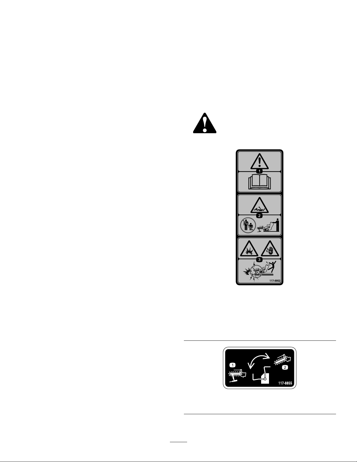
117-9952
1.Warning–readtheOperator’sManual.
2.Entanglementhazard,shaft—keepbystander’sasafe
distancefromthemachine.
3.Explosionhazard;shockhazard—donotusemachine
nearburiedutilitylines;contacttheproperagenciesbefore
digging.
•Hydrauliccouplers,hydrauliclines/valves,and
hydraulicuidmaybehotandcanburnyouifyou
touchthem.
–Weargloveswhenoperatingthehydraulic
couplers.
–Allowthetractionunittocoolbeforetouching
hydrauliccomponents.
–Donottouchhydraulicuidspills.
117–8855
1.Boredriveoperation2.Trencheroperation
3
Page 4
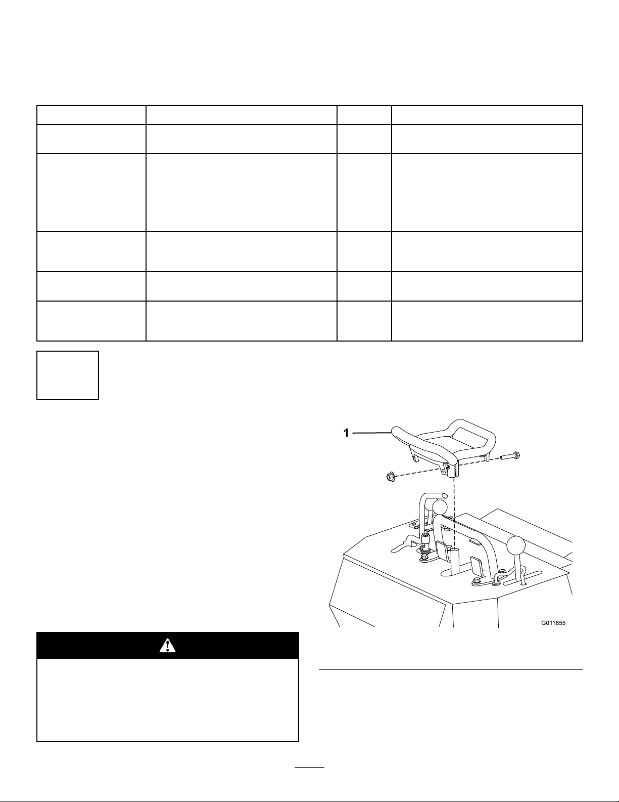
Setup
G011655
1
LooseParts
Usethechartbelowtoverifythatallpartshavebeenshipped.
ProcedureDescription
1
2
3
4
5
1
DisconnectingtheExisting
Nopartsrequired
Manifoldbracket
Carriagebolt(5/16x1inch)
Locknut(5/16inch)
Hydraulicmanifoldassembly
Hexsocket-headbolt(5/16x3-1/4
inches)
Hydraulichosewithshortelbowtting
Hydraulichosewithlongelbowtting
Hydraulichosewithstraightttings
Nopartsrequired
Rodguide,lowerhalf
Rodguide,upperhalf
Rollpin1
2.Movethehydraulicleverbackandforthafewtimes
torelieveanypressureinthelines.
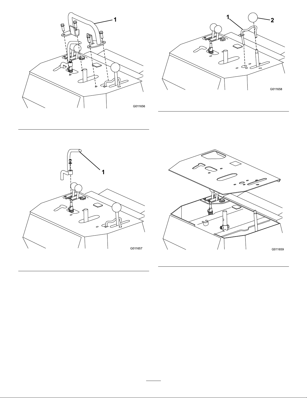
3.Removethetractionhandleandreferencebar
together(Figure2andFigure3).
Qty.
Use
–
1
1
3
1
2
1
1
2
–
1
1
Disconnecttheexistinghydraulichoses.
Installthehydraulicmanifold.
Connectthehydraulichoses.
Assemblethecontrolpanel.
Assembletherodguide.
HydraulicHoses
NoPartsRequired
Procedure
Note:Thisprocedurewillcausesomehydraulicuid
leakage.Ensurethatyouperformitinanareaequiped
tocatchoreasilycleanspilledhydraulicuid.
1.Parkthemachineonalevel,atspot,lowerthe
boom,stoptheengineandremovethekey.Ifthe
enginehasbeenrunningforawhile,thehydraulic
uidwillbewarm,allowittocoolfullybefore
proceeding.
Iftheenginehasbeenrunning,thehydraulic
uidmaybehotenoughtocausesevereburns.
Stoptheengine,removethekey,andallowthe
uidtofullycoolbeforeremovingthehydraulic
hoses.
Figure2
1.Tractioncontrolhandle
4
Page 5
G011656
1
Figure3
G011657
1
G011658
1
2
G011659
1.Referencebar
4.Disconnectthespringfromthehydraulicsleverand
removeitasshowninFigure4.
Figure5
1.Boomcontrolleverlock2.Boomcontrolleverknob
6.Removethehairpincotterandwasherfromunder
thecontrolpanelthatsecurestheboomcontrollever
lockandremovethelock(Figure5).
7.RemovethecontrolpanelasshowninFigure6.
Figure4
1.Hydraulicslever
5.Threadtheknoboffoftheboomcontrollever
(Figure5).
Figure6
8.DisconnectthehydraulichosesillustratedinFigure7
fromthehydraulicslevervalve.
5
Page 6

G011660
1
2
Figure7
G011661
1
2
3
G011662
1
1.Upperhydraulichose2.Lowerhydraulichose
9.Disconnectthehydraulichosesfromthehydraulic
motoronthetrencher(Figure8).
2
InstallingtheHydraulic
Manifold
Partsneededforthisprocedure:
1
Manifoldbracket
1
Carriagebolt(5/16x1inch)
3
Locknut(5/16inch)
1
Hydraulicmanifoldassembly
2
Hexsocket-headbolt(5/16x3-1/4inches)
Procedure
1.Installthemanifoldbrackettothetrencherframein
theholeyouopenedwhenyouremovedthehose
clamp,usingacarriagebolt(5/16x1inch)and
locknut(5/16inch)(Figure9).
Figure8
1.Hydraulicmotor
2.Righthydraulichose
3.Lefthydraulichose
10.Removeanddiscardthebolt,nut,andhoseclamp
securingthehosestothetrencherframe.
1.Manifoldbracket
2.Installthehydraulicmanifoldtothemanifoldbracket
using2hexsocket-headbolts(5/16x3-1/4inches)
Figure9
andlocknuts(5/16inch)(Figure10).
11.Removeanddiscardthehydraulichosesyou
disconnectedfromthemachine.
6
Page 7

G011663
1
Figure10
G011660
1
2
G011664
1
2
Figure11
1.Hydraulichosewiththe
longelbowtting
2.Hydraulichosewiththe
shortelbowtting
3
ConnectingtheHydraulic
Hoses
Partsneededforthisprocedure:
1
Hydraulichosewithshortelbowtting
1
Hydraulichosewithlongelbowtting
2
Hydraulichosewithstraightttings
Procedure
1.Routethehydraulichosewiththeshortelbowtting
ononeendfromthehydraulicmanifoldtothe
hydrauliclevervalvewiththeelbowttingnearthe
hydrauliclevervalve.
2.Connecttheshortelbowttingtothebottomport
onthevalve(Figure11).
3.ConnectthestraightendofthehosetoportT
(rightport)onthebackofthehydraulicmanifold
(Figure12).
Figure12
1.PortT2.PortP
4.Routethehydraulichosewiththelongelbowtting
ononeendfromthehydraulicmanifoldtothe
hydrauliclevervalvewiththeelbowttingnearthe
hydrauliclevervalve.
5.Connectthelongelbowttingtothetopporton
thevalve(Figure11).
6.ConnectthestraightendofthehosetoportP
(leftport)onthebackofthehydraulicmanifold.
(Figure12)
7.Connectahosewithstraightttingstoeachof
thetwoopenportsonthefrontofthehydraulic
manifold.
7
Page 8

8.Loopthehosesupandaroundsothattheopen
G011661
1
2
3
ttingsareattheopenportsonthehydraulicmotor
onthetrencher(Figure12).
9.Connectthelefthosetothelowerportonthemotor
(Figure13).
ensurethatthemachinetracksstraightwhen
nished.
6.Starttheengine,raisetheboom,andoperatethe
trencherchainforafewseconds.
7.Stoptheengineandremovethekey.
8.Checkallconnectionsforleaks.
Hydraulicuidescapingunderpressurecan
penetrateskinandcauseinjury.Fluidinjected
intotheskinmustbesurgicallyremovedwithin
afewhoursbyadoctorfamiliarwiththisform
ofinjuryorgangrenemayresult.
•Keepyourbodyandhandsawayfrompin
holeleaksornozzlesthatejecthighpressure
hydraulicuid.
Figure13
1.Hydraulicmotor
2.Routethishosetotherightsideofthehydraulicmanifold
3.Routethishosetotheleftsideofthehydraulicmanifold
10.Connecttherighthosetotheupperportonthe
motor(Figure13).
11.Ensurethatallhosesaretightenedsecurely.
4
AssemblingtheControlPanel
NoPartsRequired
Procedure
1.Setthecontrolpanelinplace(Figure6).
2.Installtheboomcontrolleverlockandsecureitwith
thehairpincotterandwasherremovedpreviously
(Figure5).
3.Installtheknobontheboomcontrollever(Figure5).
•Usecardboardorpapertondhydraulic
leaks,neveruseyourhands.
9.Checkthelevelofthehydraulicuid(refertothe
trencherOperator’ sManual)andtopitoffifnecessary.
5
AssemblingtheRodGuide
Partsneededforthisprocedure:
1
Rodguide,lowerhalf
1
Rodguide,upperhalf
1Rollpin
Procedure
1.Slidetheupperhalfoftherodguideintothesocket
ofthelowerhalf,ensuringthattheholesalign.
2.Securetheconnectionwitharollpin.
4.InstallthehydraulicsleverasshowninFigure4,then
attachthespringtoit.
5.Installthetractionhandleandreferencebartogether
(Figure2andFigure3).
Important:Pullthetractionhandletight
againstthereferencebarwhenyoutightenitto
8
Page 9

ProductOverview
G011665
1
2
3
G011666
1
2
Operation
Specications
Note:Specicationsanddesignaresubjecttochange
withoutnotice.
Weight
Boringdiameter
Attachments/Accessories
AselectionofToroapprovedattachmentsand
accessoriesareavailableforusewiththemachineto
enhanceandexpanditscapabilities.Contactyour
AuthorizedServiceDealerorDistributororgoto
www.Toro.comforalistofallapprovedattachments
andaccessories.
60lb(30kg)
1.25to3.5inches(3.2to8.9
cm)
ConnectingtheDriveHeadto
theTrencher
1.Raisetheboomtothehighestposition,stopthe
engine,removethekey,andsettheboomcontrol
leverlockinthelockedposition.
2.Loosenthelever-lockboltonthedriveheadand
turntheclampplatesoitisparalleltothedrive
head(Figure14).
Figure14
1.Boredrivehead
2.Lever-lockbolt
3.Clampplate
3.Slidetheboredriveheadthroughtheopeninginthe
trencherboomasshowninFigure14.
4.Rotatetheclampplate90degreesandtightenthe
lever-lockbolt;ipthelevertolockitinplace
(Figure15).
1.Clampplate
Figure15
2.Lever-lockbolt
5.Movethehydraulicsleverbackandforthafew
timestorelievepressureinthesystem.
9
Page 10

6.Lowertheswitchingleveronthehydraulics
G011800
1
manifoldtoswitchfromtrencheroperationtobore
driveheadoperation(Figure16).
1.Accessoryshaft
2.Socket
Figure17
3.Pushbuttonconnector
4.Hole
Figure16
1.Switchinglever(showninboredriveoperationposition)
7.Connectthemaleandfemalecouplersonthebore
driveheadhosestotheappropriatecouplersonthe
hydraulicmanifold.
Note:Toremovetheboredrivehead,raisetheboom
tothehighestposition,stoptheengine,removethe
key,andsettheboomcontrolleverlockinthelocked
position,thenreversethisprocedure.
InstallingAccessories
Torooffersseveraldifferentrodsandbitsforusewith
theattachment.PurchaseaccessoriesfromyourToro
dealer.
1.Stoptheengine,waitforallmovingpartstostop,
andremovethekey.
2.Slidethehexshaftofarod,boringbit,orreamer
intothesocket.Aligntheholeinthesocketwith
thepushbuttonconnector(Figure17).
3.Pressdownthepushbuttonconnectorandpush
theshaftintothesocketuntiltheconnectorsnaps
intotheholeinthesocket(Figure17).
4.Repeatsteps2and3asneededtoaddparts.
RemovinganAccessory
1.Stoptheengine,waitforallmovingpartstostop,
andremovethekey.
2.Pressthepushbuttonconnectorsecuringthe
accessoryshaftinthesocketandpulltheaccessory
freeofthesocket.
BoringaHole
DiggingtheTrenches
Beforedrillingunderawalkordriveway,youmust
makeanentranceandanexittrenchoneithersideof
thedrillingarea.Bothtrenchesmustbeatleast6inches
wideand18inchesdeep.Theentrancetrenchmustbe
atleast7feetlongandtheexittrench3to6feetlong.
Theentrancetrenchshouldbeperpendiculartothe
walkordriveway5andtheexittrenchshouldbeparallel
tothewalkordriveway.Theexittrenchshouldbe
centeredacrossfromtheentrancetrench(Figure18).
10
Page 11

Figure18
1.Entrancetrench3.Exittrench
2.Sidewalk
6.Slowlymovethetractionunitforward,whilethe
personwiththerodguidetoolguidestheboringbit
intothesoil(Figure19).
7.Oncetheentiredrillbitisinthesoil,releasethe
hydraulicslever.
8.Stoptheengineandwaitforallmovingpartsto
stop.
9.Checkthegradeoftherod.
Iftherodisnotwithinthegradetolerancesforthe
jobbeingperformed,starttheengineanddrive
backwardtopulltheboringbitoutofthesoil,then
repeatsteps5through9,makingadjustmentsto
correctthegrade.
10.Removetherodguidetool.
BoringtheHole
Important:Boringisatwopersonoperation.Do
notattempttoperformthisoperationbyyourself.
1.Positionthetractionunitwiththedriveheadat
thebeginningofthetrenchandlowerittothe
appropriatedepth.
2.Stoptheengineandwaitforallmovingpartsto
stop.
3.Connectarodandboringbitontothedrivehead.
4.Connecttherodguidetooltotherodjustbehind
theboringbit(Figure19).
11.Starttheengineandholdthehydraulicslevertothe
referencebartostarttheboringbit.
12.Slowlymovethetractionunitforwardastheboring
bitdigsintothesoil.
Important:Donotdrivetoofast,forcingthe
bitintothesoil.Allowthebittoprogressatits
ownrate.Neverpushorpullthebitthrough
thesoilwhenthedriveheadisnotturning.
13.Whenabout6inches(15cm)ofrodareleft
showingintheentrancetrenchorwhentheboring
bitcompletelyentersandboresintothefarsideof
theexittrench,stopthetractionunit,releasethe
hydraulicslever,andstoptheengine.
14.Iftheboringbithasnotyetenteredtheexittrench,
completethefollowing:
A.Detachtherodfromthedrivehead.
B.Starttheengineandbackuptotheendofthe
entrancetrench.
C.Stoptheengineandwaitforallmovingparts
tostop.
Figure19
1.Sidewalkordriveway
2.Entrancetrench5.Rodguidetool
3.Boringbit
4.Rod
5.Withthepersonguidingtheboringbitpositioned
totherightofthetrench(Figure19),startthe
engine,positionthethrottletowithinthemiddle
oftheRPMrange,andholdthehydraulicsleverto
thereferencebartostarttheforwardrotationof
theboringbit.
D.Connectanotherrodandrepeatsteps11
through14.
ReamingtheHole
1.Withashovel,carefullydigaroundtheboringbit
clearingitofsoiluntilitcanberemoved(Figure20).
11
Page 12

Figure20
1.Sidewalkordriveway
2.Exittrench
3.Shoveldugareaaround
bit
4.Reamer
5.Swivel
2.Removetheboringbitandattachthereamer
(Figure20).
3.Attachthecableorpipingbeinginstalledtothe
swivelontheendofthereamer(Figure20).
Storage
1.Beforelongtermstorage,washtheattachmentwith
milddetergentandwatertoremovedirtandgrime.
2.Checktheconditionofthehydraulichoses.Replace
anydamagedhoses.
3.Ensurethatallhydrauliccouplersareconnected
togethertopreventcontaminationofthehydraulic
system.
4.Checkandtightenallbolts,nuts,andscrews.Repair
orreplaceanydamagedorwornpart.
5.Paintallscratchedorbaremetalsurfaces.Paintis
availablefromyourAuthorizedServiceDealer.
6.Storetheattachmentinaclean,drygarageorstorage
area.Coverittoprotectitandkeepitclean.
4.Starttheengineandholdthehydraulicslevertothe
referencebartostartthereamer.
5.Slowlymovethetractionunitrearwardasthe
reamerdigsintothesoil.
Important:Donotdrivetoofast,forcing
thereamerintothesoil.Allowthereamerto
progressatitsownrate.Neverpushorpullthe
reamerthroughthesoilwhenthedrivehead
isnotturning.
6.Whenarodcouplingisabout6inches(15cm)into
theentrancetrenchorwhenthereamercompletely
entersthetrenchwithabout6inches(15cm)ofthe
cableorpiping,stopthetractionunit,releasethe
hydraulicslever,andstoptheengine.
7.Ifthereamerhasnotyetenteredtheexittrench,
completethefollowing:
A.Detachtherodfromthedriveheadandrodstill
inthesoil.
B.Starttheengineandmovetothefrontofthe
entrancetrench.
C.Stoptheengineandwaitforallmovingparts
tostop.
D.Connectthedriveheadtotherodshaftinthe
soil.
E.Repeatsteps4through7.
8.Withthereamerandcable/pipingintheentrance
trench,removethecableorpipingfromthereamer.
12
Page 13

Notes:
13
Page 14

Notes:
14
Page 15

Notes:
15
Page 16

Toro Compact Utility Equipment Warranty
A One-Year Limited Warranty
CUE Products
The Toro® Company and its affi liate, Toro Warranty Company, pursuant
Conditions and Products Covered
to an agreement between them, jointly warrant your Toro Compact Utility
Equipment (“Product”) to be free from defects in materials or workmanship.
The following time periods apply from the date of purchase:
Products Warranty Period
Loaders, Trenchers and 1 year or 1000 operating
Attachments hours, whichever occurs
fi rst
Kohler Engines 3 years
All other Engines 2 years
Where a warrantable condition exists, we will repair the Product at no cost
to you including diagnosis, labor, and parts.
Instructions for Obtaining Warranty Service
If you think that your Toro Product contains a defect in materials or workmanship, follow this procedure:
1. Contact any Authorized Toro Compact Utility Equipment (CUE) Service
Dealer to arrange service at their dealership. To locate a dealer convenient to you, access our website at www.Toro.com. You may also call our
Toro Customer Care Department toll free at 888-865-5676 (U.S. customers) or 888-865-5691 (Canadian customers).
2. Bring the product and your proof of purchase (sales receipt) to the
Service Dealer.
If for any reason you are dissatisfi ed with the Service Dealer’s analysis or
with the assistance provided, contact us at:
LCB Customer Service Department
Toro Warranty Company
8111 Lyndale Avenue South
Bloomington, MN 55420-1196
Toll Free: 888-865-5676 (U.S. customers)
Toll Free: 888-865-5691 (Canada customers)
Owner Responsibilities
You must maintain your Toro Product by following the maintenance procedures described in the Operator’s Manual. Such routine maintenance,
whether performed by a dealer or by you, is at your expense. Parts scheduled for replacement as required maintenance (“Maintenance Parts”), are
warranted for the period of time up to the scheduled replacement time for
that part. Failure to perform required maintenance and adjustments can be
grounds for disallowing a warranty claim.
Not all product failures or malfunctions that occur during the warranty period are defects in materials or workmanship. This express warranty does
not cover the following:
Product failures which result from the use of non-Toro replacement
•
parts, or from installation and use of add-on, modifi ed, or unapproved
accessories
Product failures which result from failure to perform required mainte-
•
nance and/or adjustments
Product failures which result from operating the Product in an abusive,
•
negligent or reckless manner
Parts subject to consumption through use unless found to be defec-
•
tive. Examples of parts which are consumed, or used up, during normal
Product operation include, but are not limited to, digging teeth, tines,
spark plugs, tires, tracks, fi lters, chains, etc.
Failures caused by outside infl uence. Items considered to be outside
•
infl uence include, but are not limited to, weather, storage practices,
contamination, use of unapproved coolants, lubricants, additives, or
chemicals, etc.
Normal “wear and tear” items. Normal “wear and tear” includes, but is
•
not limited to, worn painted surfaces, scratched decals or windows, etc
Any component covered by a separate manufacturer’s warranty
•
Pickup and delivery charges
•
Repair by an Authorized Toro Compact Utility Equipment (CUE) Service
Dealer is your sole remedy under this warranty. Neither The Toro®
Company nor Toro Warranty Company is liable for indirect, incidental or consequential damages in connection with the use of the Toro
Products covered by this warranty, including any cost or expense of
providing substitute equipment or service during reasonable periods
of malfunction or non-use pending completion of repairs under this
warranty. All implied warranties of merchantability and fi tness for
use are limited to the duration of this express warranty. Some states
do not allow exclusions of incidental or consequential damages, or
limitations on how long an implied warranty lasts, so the above exclusions and limitations may not apply to you. This warranty gives you
specifi c legal rights, and you may also have other rights which vary from
state to state.
Except for the engine warranty coverage and the Emissions warranty referenced below, if applicable, there is no other express warranty.
The Emissions Control System on your Product may be covered by a separate warranty meeting requirements established by the U.S. Environmental
Protection Agency (EPA) or the California Air Resources Board (CARB).
The hour limitations set forth above do not apply to the Emissions Control
System Warranty. Refer to the California Emission Control Warranty Statement printed in you operator’s manual or contained in the engine manufacturer’s documentation for details.
Items and Conditions Not Covered
General Conditions
Customers who have purchased Toro products exported from the United States or Canada should contact their Toro Distributor (Dealer) to obtain guarantee policies for your country, province, or state. If for any reason you are dissatisfi ed with your Distributor’s service or have diffi culty obtaining guarantee
information, contact the Toro importer. If all other remedies fail, you may contact us at Toro Warranty Company.
Countries Other than the United States or Canada
Part Number 374-0198 Rev. A
 Loading...