

Page 1

FR651V, FR691V, FR730V
FS651V, FS691V, FS730V
FX651V, FX691V, FX730V
4-Stroke Air-Cooled V-Twin Gasoline Engine
Service Manual
Page 2

Page 3

Quick Reference Guide
j
j
j
j
j
j
j
j
j
j
General Information 1
Periodic Maintenance 2
Fuel System 3
Cooling System 4
Engine Top End 5
Lubrication System 6
Camshaft/Crankshaft 7
Starter System 8
This quick reference guide will assist
you in locating a desired topic or procedure.
•Bend the pages back to match the
black tab of the desired chapter number with the black tab on the edge at
each table of contents page.
•Refertothe sectional tableofcontents
for the exact pages to locate the specific topic required.
Electrical System 9
Troubleshooting 10
Page 4

Page 5

FR651V, FR691V, FR730V
FS651V, FS691V, FS730V
FX651V, FX691V, FX730V
4-Stroke Air-Cooled V-Twin Gasoline Engine
Service Manual
All rights reserved. No parts of this publication may be reproduced, stored in a retrieval system, or
transmitted in any form or by any means, electronic mechanical photocopying, recording or otherwise,
without the prior written permission of Quality Assurance Division/Consumer Products & Machinery
Company/Kawasaki Heavy Industries, Ltd., Japan.
No liability can be accepted for any inaccuracies or omissions in this publication, although every possible
care has been taken to make it as complete and accurate as possible.
The right is reserved to make changes at any time without prior notice and without incurring an obligation
to m ake such changes to products manufactured previously.
All information contained in this publication is based on the latest product information available at the time
of publication. Illustrations and photographs in this publication are intended for reference use only and may
not depict actual model component parts.
© 2009 Kawasaki Heavy Industries, Ltd. First Edition (1):Jan. 9, 2009 (K)
Page 6

LIST OF ABBREVIATIONS
A ampere(s) lb pound(s)
ABDC after bottom dead center
AC
ATDC after top dead center N newton(s)
BBDC before bottom dead center Pa pascal(s)
BDC bottom dead center PS horsepower
BTDC before top dead center psi pound(s) per square inch
°C degree(s) Celsius r revolution
DC direct current rpm revolution(s) per minute
F farad(s) TDC top dead center
°F degree(s) Fahrenheit TIR total indicator reading
ft foot, feet V volt(s)
g gram(s) W watt(s)
h
L
alternating current min
hour(s) Ω ohm(s)
liter(s)
m
meter(s)
minute(s)
Page 7

EMISSION CONTROL INFORMATION
Toprotect the environment in which weall live, Kawasaki has incorporatedcrankcaseemission
(1) and exhaust emission (2) control systems (EM) in compliance with applicable regulations of
the United States Environmental P rotection Agency and California Air Resources Board.
1. Crankcase Emission Control System
A sealed-type crankcase emission control system is used to eliminate blow-by gases. The
blow-by gases are led to the breather chamber through the crankcase. Then, it is led to the air
cleaner.
Oil is separated from the gases while passing through the inside of the breather chamber from
the crankcase, and then returned back to the bottom of crankcase.
2. Exhaust Emission Control System
The exhaust emission control system applied to this engine consists of a carburetor and an
ignition system having optimum ignition timing characteristics.
The carburetor has been calibrated to provide lean air/fuel mixture characteristics and opti-
mum fuel economy with a suitable air cleaner and exhaust system.
TAMPERING WITH EMISSION CONTROL SYSTEM PROHIBITED
Federal law and California State law prohibits the following acts or the causing thereof: (1) the
removal or rendering inoperative by any person other than for purposes of maintenance, repair,
or replacement, of any device or element of design incorporated into any new engine for the
purpose of emission control prior to its sale or delivery to the ultimate purchaser or while it is in
use, or (2) the use of the engine after such device or element of design has been removed or
rendered inoperative by any person.
Among those acts presumed to constitute tampering are the acts listed below:
Do not tamper w ith the original emission related part:
Carburetor and internal parts
•
Spark plugs
•
Magneto or electronic ignition system
•
Fuel filter element
•
Air cleaner elements
•
Crankcase
•
Cylinder heads
•
Breather chamber and internal parts
•
Inlet pipe and tube
•
Page 8
Foreword
This manual is designed primarily for use by
trainedmechanics in a properly equipped shop.
However,itcontainsenough detailand basic i nformationto make ituseful to theowner who desiresto perform his own basicmaintenance and
repair work. A basic knowledge of mechanics,
the proper use of tools, and workshop procedures must be understood in order to carry out
maintenance and repair satisfactorily. Whenever the owner has insufficient experience or
doubts as to his ability to do the work, all adjustments, maintenance, and repair should be
carried out only by qualified mechanics.
In order to perform the work efficiently and
to avoid costly mistakes, read the text, thoroughly familiarize yourself with the procedures
beforestarting work, and then do the workca
fully in a clean area. Whenever special tools or
equipment are specified, do not use makeshift
tools or equipment. Precision measurem
can only be made if the proper instruments are
used, and the use of substitute tools may adversely affect safe operation.
To get the longest life out of your engine:
Follow the Periodic Maintenance Chart in the
•
Service Manual.
Be alert for problems and non-scheduled
•
maintenance.
Use proper tools and genu
•
gine parts. Genuine parts provided as spare
parts are listed in the Parts Catalog.
Follow the procedure
•
fully. Don’t take shortcuts.
Remembertokeep complete records ofmain-
•
tenance and repair
parts installed.
with dates and any new
ine Kawasaki en-
s in this manual care-
re-
ents
How to Use This Manual
In this manual, the product is divided into
its major systems and these systems make up
the manual’s chapters. The Quick Reference
Guide shows you all of the product’s system
and assists in locating their chapters. Each
chapter in turn has its own comprehensive Table of Contents.
For, example, ifyou want ignition coil information, use the Quick Reference Guide to locate
the Electrical System chapter. Then, use the
Table of Contents on the first page of the chapter to find the Ignition Coil section.
Whenever you see these WARNING and
CAUTION symbols, heed their instructions!
Always follow safe operating and maintenance
practices.
WARNING
This warning symbol identifies special
instructions or procedures which, if not
correctly followed, could result in per-
sonal injury, or loss of life.
CAUTION
This caution symbol identifies special
instructions or procedures which, if not
strictly observed, could result in dam-
age to or destruction of equipment.
This manual contains four more symbols (in
additiontoWARNINGandCAUTION)whichwill
help you distinguish different types of information.
NOTE
This note symbol indicates points of par-
○
ticular interest for more efficient and con-
venient operation.
Indicates a procedural step or work to be
•
done.
Indicates a procedural sub-step or how to do
○
the work of the procedural step it follows. It
also precedes the text of a WA
TION, or NOTE.
Indicates a conditional step or what action to
takebased on theresults o
tion in the procedural step or sub-step it fol-
lows.
In most chapters an e
of the system components follows the Table of
Contents. In these illustrations you will find the
instructionsind
ified tightening torque, oil, grease or a locking
agent during assembly.
icatingwhich parts require spec-
xploded view illustration
RNING, CAU-
fthe test or inspec-
Page 9

GENERAL INFORMATION 1-1
General Information
Table of Contents
Before Servicing ..................................................................................................................... 1-2
Model Identification................................................................................................................. 1-5
General Specifications............................................................................................................ 1-7
1
Page 10

1-2 GENERAL INFORMATION
Before Servicing
Before starting to service the engine, carefully read the applicable section to eliminate unnecessary
work. Photographs, diagrams, notes, cautions, warnings, and detailed descriptions have been included wherever necessary. Nevertheless, even a detailed account has limitations, a certain amount
of basic knowledge is required for successful work.
Especially note the following
(1) Dirt
Before removal and disassembly, clean the engine. Any dirt entering the engine, carburetor, or
other parts, will work as an abrasive and shorten the life of engine. For the same reason, before
installing a new part, clean off any dust or metal filings.
(2) Battery Ground
Remove the ground (–) lead from the battery before performing any disassembly operations on
the equipment. This prevents:
(a)t he possibility of accidentally turning the engine over while partially disassembled.
(b)sparks at electrical connections which will occur when they are disconnected.
(c)damage t o electrical parts.
(3) Tightening Sequence
Generally, when installing a part with several bolts, nuts, or screws, start them all in their holes
and tighten them to a snug fit. Then tighten them evenly, in a staggered sequence. This is to
avoid distortion of the part and/or causing gas or oil leakage. Conversely when loosening the
bolts, nuts, or screws, first loosen all of them by about a quarter of a turn and then remove them.
Where there is a tightening sequence indication in this Service Manual, the bolts, nuts, or screws
must be tightened in the order and method indicated.
(4) Torque
When torque values are given in this Service Manual, use them. Either too little or too much
torque may lead to serious damage. Use a good quality, reliable torque wrench.
(5) Force
Common sense should dictate how much force is necessary in assembly and disassembly. If
a part seems especially difficult to remove or install, stop and examine what may be causing the
problem. Whenever tapping is necessary,tap lightly using a wooden or plastic-faced mallet. Use
an impact driver f or screws (particularlyfor the removal of screws held by a locking agent) in order
to avoid damaging the heads.
(6) Edges
Watchfor sharp edges, especiallyduring major engine disassembly and assembly. Protect your
hands with gloves or a piece of thick cloth when lifting the engine or turning it over.
(7) High-Flash Point Solvent
A high-flash point solvent is recommended to reduce fire danger. A commercial solvent commonlyavailable in North America is Standard solvent (genericname). Alwaysfollow manufacturer
and container directions regarding the use of any solvent.
(8) Gasket, O-ring
Do not reuse a gasket or O-ring once it has been in service. The mating surfaces around the
gasket should be free of foreign matter and perfectly smooth to avoid oil or compression leaks.
(9) Liquid Gasket, Non-Permanent Locking Agent
Follow manufacturer ’s directions for cleaning and preparing surfaces where these compounds
will be used. Apply sparingly. Excessive amounts may block engine oil passages and cause
serious damage. An example of a non-permanent locking agent commonly available in North
America is Loctite Lock’n Seal (Blue).
(10)Press
A part installed using a press or driver, such as a journal, should first be coated with oil on its
outer or inner circumference so that it will go into place smoothly.
(11)B all Bearing, Needle Bearing
Do not remove a ball bearing or a needle bearing unless it is absolutely necessary. Replace any
ball or needle bearings that were removed with new ones. Install bearings with the manufacturer
and size marks facing out, applying pressure evenly with a suitable driver to the end of the race
that contacts the press fit portion, and press it evenly over the base component.
Page 11
GENERAL INFORMATION 1-3
Before Servicing
(12)Oil Seal and Grease Seal
Replace any oil or grease seals that were removed with new ones, as removal generally dam-
ages seals.
When pressing in a seal which has manufacturer’s marks, press it in with the marks facing out.
Seals should be pressed into place using a suitable driver, which contacts evenly with the side of
seal, until the face of the seal is even with the end of the hole.
(13)Seal Guide
A seal guide is required for certain oil or grease seals during installation to avoid damage to
the seal lips. Before a shaft passes through a seal, apply a little oil, preferably high-temperature
grease on the lips to reduce rubber to metal friction.
(14)Circlip, Retaining Ring and Cotter Pin
When installing circlips and retaining rings, take care to compress or expand them only enough
to install them and no more. Install the circlip with i ts chamfered side facing load side as well.
Replace any circlips, retaining rings, and cotter pins that were removed with new ones, as removal weakens and deforms them. If old ones are reused, they could become detached while
running, leading to a problem.
(15)Lubrication
Engine wear is generally at its maximum while the engine is warming up and before all the
rubbing surfaces have an adequate lubricative film. During assembly, oil or grease ( whichever
is more suitable) should be applied to any rubbing surface which has lost its lubricative film. Old
grease and dirty oil should be cleaned off. Deteriorated grease has lost its lubricative quality and
may contain abrasive foreign particles.
Don’t use just any oil or grease. Some oils and greases in particular should be used only in
certain applications and may be harmful if used in an application for which they are not intended.
This manual makes reference to molybdenum disulfide grease (MoS2) in the assembly of certain
engine parts. Always check manufacturer recommendations before using such special lubricants.
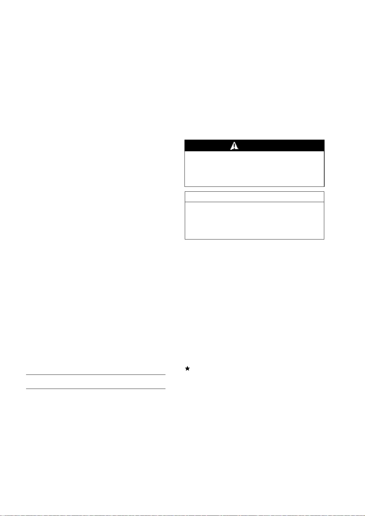
(16)Electrical Wires
All the electrical wires are either single-color or two-color and, with only a few exceptions, must
be connected to wires of the same color. On any of the two-color wires there is a greater amount
of one color and a lesser amount of a second color, so a two-color wire is identified by first the
primary color and then the secondary color. For example, a yellow wire with thin red stripes is
referred to as a “yellow/red” wire; it would be a “red/yellow” wire if the colors were reversed to
make red the main color.
(17)Replacement Parts
When there is a replacement instruction, replace these parts with new ones every time they are
removed. There replacement parts will be damaged or lose their original function once removed.
(18)Inspection
When parts have been disassembled, visually inspect these parts for the following conditions
or other damage. If there i s any doubt as to the condition of them, replace them with new ones.
Abrasion Crack Hardening Warp
Bent Dent Scratch Wear
Color change Deterioration Seizure
(19)Service Data
Service Data terms are defined as follows:
“Standards” show dimensions or performances which brand-new parts or systems have.
Page 12

1-4 GENERAL INFORMATION
Before Servicing
“Service Limits” indicate the usable limits. If the measurement shows excessive wear or deteri-
orated performance, replace the dam aged parts.
Page 13

Model Identification
FX Models
GENERAL INFORMATION 1-5
FR M odels
Page 14

1-6 GENERAL INFORMATION
Model Identification
FS M odels
Cylinder Number Designation:
No.1 C ylinder is the left-hand cylinder viewed from the inlet pipe.
No.2 C ylinder is the right-hand cylinder viewed from the inlet pipe.
Page 15

General Specifications
GENERAL INFORMATION 1-7
Item
Type of Engine Forced air-cooled, vertical shaft, OHV, 4-stroke gasoline engine
Cylinder Layout 90 V-Twin
Bore × Stroke 78 mm × 76 mm (3.07 in. × 2.99 in.)
Piston Displacement 726 cm³ (44.3 cu in.)
Direction of Rotation Counterclockwise facing the PTO shaft
Compression Release Automatic compression release
Low Idle Speed 1 550 r/min (rpm)
High Idle Speed 3 600 r/min (rpm)
Ignition System Transistorized-flywheel magneto
RFI Per Canada and U.S.A. requirements
Starting System:
FR and FS Models Electric starter
FX Models Shift type electric starter
Charging System:
FS and FX Models 12 V - 15 amps with regulator
FR Models 12 V - 3.6 amp without regulator
Spark Plug NGK BPR4ES
Carburetor:
FR and FS Models Float type, fixed main jet, internally vented, single barrel
FX Models Float type, fixed main jet, internally vented, two barrel
Fuel Pump Diaphragm type pulse pump
Air Cleaner:
FR Models Single stage element, dry type
FS Models Dual stage element, dry type
FX Models Dual stage element, heavy duty type
Governor Flyweight all speed governor
Lubrication System Pressure feed by positive displacement pump
Oil Filter Cartridge type full flow filter
Oil Capacity (when engine
is completely dry)
Cooling System Forced air cooling by fan
Dimensions (L × W × H ):
FR Models
FS Models 481 mm × 424 m m × 380 mm (18.9 in. × 16.7 in. × 15.0 in.)
FX Models 478 mm × 424 m m × 549 mm (18.8 in. × 16.7 in. × 21.6 in.)
Dry Weight (withoutmuffler):
FR Models 40.0 kg (88.2 lb)
FS Models 41.0 kg (90.4 lb)
FX Models 46.0 kg (101.4 lb)
2.0 L (2.1 US qt)
481 mm × 424 m m × 380 mm (18.9 in. × 16.7 in. × 15.0 in.)
FR651V,FR691V,FR730V, FS651V,FS691V, FS 730V,
FX651V, FX691V, FX730V
Specifications are subject to change without notice.
Page 16

Page 17

PERIODIC MAINTENANCE 2-1
Periodic Maintenance
Table of Contents
Periodic Maintenance Chart ................................................................................................... 2-2
Torque and Locking Agent...................................................................................................... 2-3
Specifications ......................................................................................................................... 2-5
Special Tools .......................................................................................................................... 2-6
Periodic Maintenance Procedures.......................................................................................... 2-7
Fuel System......................................................................................................................... 2-7
Low Idle Speed Adjustment.............................................................................................. 2-7
High Idle Speed Adjustment ............................................................................................. 2-7
Fuel System Cleanliness Inspection................................................................................. 2-8
Element Cleaning and Inspection..................................................................................... 2-9
Air Cleaner Housing (Cap and Body) Inspection.............................................................. 2-10
Engine Top End ................................................................................................................... 2-10
Cylinder Head Cleaning.................................................................................................... 2-10
Va lve Clearance Inspection .............................................................................................. 2-10
Va lve Clearance Adjustment............................................................................................. 2-11
Va lve Seat Inspection ....................................................................................................... 2-12
Valve Seat Repair............................................................................................................. 2-12
Lubrication System.............................................................................................................. 2-15
Engine Oil Level Inspection .............................................................................................. 2-15
Engine Oil Change............................................................................................................ 2-15
Oil Filter Replacement ...................................................................................................... 2-16
Electrical System................................................................................................................. 2-17
Spark Plug Cleaning and Inspection................................................................................. 2-17
Spark Plug Gap Inspection ............................................................................................... 2-17
2
Page 18

2-2 PERIODIC MAINTENANCE
Periodic Maintenance Chart
To ensure satisfactory operation over an extended period of t ime, any engine requires normal maintenance regular intervals. The Periodic Maintenance Chart below shows periodic inspection and
maintenance items and suitable intervals. The bullet mark (
should be performed at that interval.
Some adjustments require the use of special tools or other equipment. An electronic tachometer
will facilitate setting idle and running speeds.
OPERATION
Daily
Check or clean air inlet screen
(1)
First
8hr.
Every
25 hr.
•
) designates that the corresponding item
•
INTERVAL
Every
100 hr.
Every
200 hr.
Every
250 hr.
Every
300hr.
Every
500 hr.
Check and add engine oil
Check for fuel and oil leakage
Check for loose or lost nuts and
screws
Check battery electrolyte level
Replace air cleaner primary
element (Heavy Duty Air
Cleaner) (FX Models) (1)
Check air cleaner secondary
element (Heavy Duty Air
Cleaner) (FX Models) (1)
Replace air cleaner secondary
element (Heavy Duty Air
Cleaner) (FX Models) (1)
Clean air cleaner foam element
(FS Models) (1)
Clean air cleaner paper element
(FR and FS Models) (1)
Replace air cleaner paper
element (FR and FS Models) (1)
Clean dust and dirt from cylinder
and cylinder head fins (1)
•
•
•
•
•
•
•
•
•
•
•
Tighten nuts and screws
Change engine oil
Clean and re-gap spark plugs
Change oil filter
Check and adjust valve
♦
clearance
Clean and lap valve seating
♦
surface
♦
Clean combustion chambers
(1): Service more frequently under dusty conditions.
♦: These items must be performed with the proper tools. See your authorized Kawasaki Engine
Dealer for service, unless you have the proper equipment and mechanical proficiency.
• •
•
•
•
•
•
•
Page 19
PERIODIC MAINTENANCE 2-3
Torque and Locking Agent
The following tables list the tightening torque for the major fasteners and the parts requiring use of
a non-permanent locking agent or liquid gasket.
Letters used in the “Remarks” column mean:
EO: Apply oil to the threads.
L: Apply a non-permanent locking agent to the threads.
Lh: Left-hand threads.
S: Tighten the fasteners following the specified sequence.
Fastener
Fuel System
Carburetor and Inlet Pipe Mounting Nuts 5.9 0.60 52 in·lb
Control Panel Mounting Bolt 5.9 0.60 52 in·lb
Governor Arm Clamp Nut 7.8 0.80 69 in·lb
Governor Arm Joint Bolt 5.9 0.60 52 in·lb Lh
Governor Shaft Plate Screws 2.0 0.20 18 in·lb
Inlet Manifold Bolts
FX Models
Air Cleaner Bracket Mounting Bolts 5.9 0.60 52 in·lb
Air Cleaner Holder Bracket Bolts
Carburetor and Inlet Pipe Mounting B olts
Choke Valve Screws 0.93 0.095 8.2 in·lb
Cover Plate Screw 2.4 0.24 21 in·lb
Drain Screw 2.0 0.20 18 in·lb
Float C hamber Mounting Screws 3.9 0.40 35 in·lb
Throttle Valve Screws 0.93 0.095 8.2 in·lb
FR and FS Models
Control Panel and Inlet Pipe Mounting Bolt 5.9 0.60 52 in·lb
Main Jet 2.3 0.23 20 in·lb
Solenoid Valve 4.5 0.46 40 in·lb
Throttle Valve Screws 0.68 0.069 6.0 in·lb L
FR651V, FR691V, FS651V, FS691V Models
Throttle Lever Mounting Screw 0.68 0.069 6.0 in·lb L
Cooling System
Cooling Fan Plate Mounting Bolts
Cooling Fan Screen Bolts
Flywheel Bolt 56 5.7 41
FX Models
Engine Shroud Bolts 5.9 0.60 52 in·lb
Fan Housing Bolts 5.9 0.60 52 in·lb
Guard Mounting Bolts 5.9 0.60 52 in·lb
FR and FS Models
Engine Shroud Bolts 8.8 0.90 78 in·lb
Fan Housing Bolts 8.8 0.90 78 in·lb
Engine Top End
Connecting Rod Big End C ap Bolts 9.8 1.0 87 in·lb EO
Cylinder Head Bolts (L = 50 mm) 46 4.7 34 S
N·m kgf·m ft·lb
5.9 0.60 52 in·lb
5.9 0.60 52 in·lb
5.9 0.60 52 in·lb
8.8 0.90 78 in·lb
5.9 0.60 52 in·lb
Torque
Remarks
S
Page 20

2-4 PERIODIC MAINTENANCE
Torque and Locking Agent
Fastener
Cylinder Head Bolts (L = 60 mm) 46 4.7 34 S
Rocker Arm Bracket Bolts 14.7 1.5 11 L
Rocker Cover Bolts
Spark Plugs 22 2.2 16
Valve Clearance Adjusting Locknuts 11 1.1 97 in·lb
Lubrication System
Engine Oil Drain Plug 6.9 0.70 61 in·lb
Oil Pump Cover Plate Bolts 5.9 0.60 52 in·lb
FX Models
Oil Filler Mounting Bolt 5.9 0.60 52 in·lb
FR and FS Models
Oil Filler Mounting Bolt 8.8 0.90 78 in·lb
Camshaft/Crankshaft
Connecting Rod Big End Cap Bolts 9.8 1.0 87 in·lb EO
Crankcase C over Bolts 27.4 2.8 20 S
Crankcase Cover Oil Passage Plugs 3.9 0.40 35 in·lb L
Crankcase Oil Passage Plugs
Breather Chamber Cover Bolts
Breather Valve Mounting Screw 2.0 0.20 18 in·lb
Starter System
Starter Motor Mounting Bolts 19.6 2.0 14
FR and FS Models
Starter Motor Through Bolts 3.95 0.40 35 in·lb
Electrical System
Flywheel Bolt 56 5.7 41
Ignition Coil Bolts 5.9 0.60 52 in·lb
Spark Plugs 22 2.2 16
Stator Coil Screws 3.4 0.35 30 in·lb
N·m
5.9 0.60 52 in·lb
3.9 0.40 35 in·lb L
5.9 0.60 52 in·lb
Torque
kgf·m ft·lb
Remarks
The table below, relating tightening torque to thread diameter, lists the basic torque for the bolts and
nuts. Use this table for only the bolts and nuts which do not require a specific torque value. All of the
values are for use with dry solvent-cleaned threads.
Basic Torque for General Fasteners
Threads Diameter
(mm)
4 2.0 0.20 17 in·lb
5 3.4 0.35 30 in·lb
6 5.9 0.60 52 in·lb
8 15 1.5 11
10 20 2.0 15
N·m kgf·m ft·lb
Torque
Page 21

PERIODIC MAINTENANCE 2-5
Specifications
Item Standard
Fuel System
Idle Speed (1):
Low Idle Speed (Carburetor idle rpm) 1 450 r/min (rpm)
Low Idle Speed (Governor idle rpm) 1 550 r/min (rpm)
High Idle Speed 3 600 r/min (rpm)
Air Cleaner:
Type:
FR Models Single stage filtration system
FS and FX M odels Dual stage filtration system
Pre-cleaner:
FR Models Paper element
FS Models Foam element
FX Models P aper element
Second-stage cleaner:
FS Models P aper element
FX Models Foam element
Engine Top End
Valve Clearance:
Inlet, Exhaust 0.05 ∼ 0.10 mm (0.0020 ∼ 0.0039 in.)
Valve Seating Surface Angle:
Inlet, Exhaust 45°
Valve Seating Surface Width:
Inlet 1.2 ∼ 1.8 mm (0.047 ∼ 0.071 in.)
Exhaust 0.8 ∼ 1.6 m m (0.031 ∼ 0.063 in.)
Lubrication System
Engine Oil:
Type SF, SG, SH, SJ or SL class
Viscosity SAE 40, SAE 30, SAE 10W-30/SAE 10W-40, or
SAE 5W-20
Capacity 1.8 L (1.9 US qt) (When the oil filter is not removed)
2.1 L (2.2 US qt) (When the oil filter is removed)
Level Operating range (grid area (ADD and FULL)) on dipstick
Electrical System
Spark Plug NGK BPR4ES
Spark Plug Gap 0.7 ∼ 0.8 mm (0.028 ∼ 0.031 in.)
(1) Idle speeds may vary depending on each equipment. Refer to the equipment specification.
Page 22
2-6 PERIODIC MAINTENANCE
Special Tools
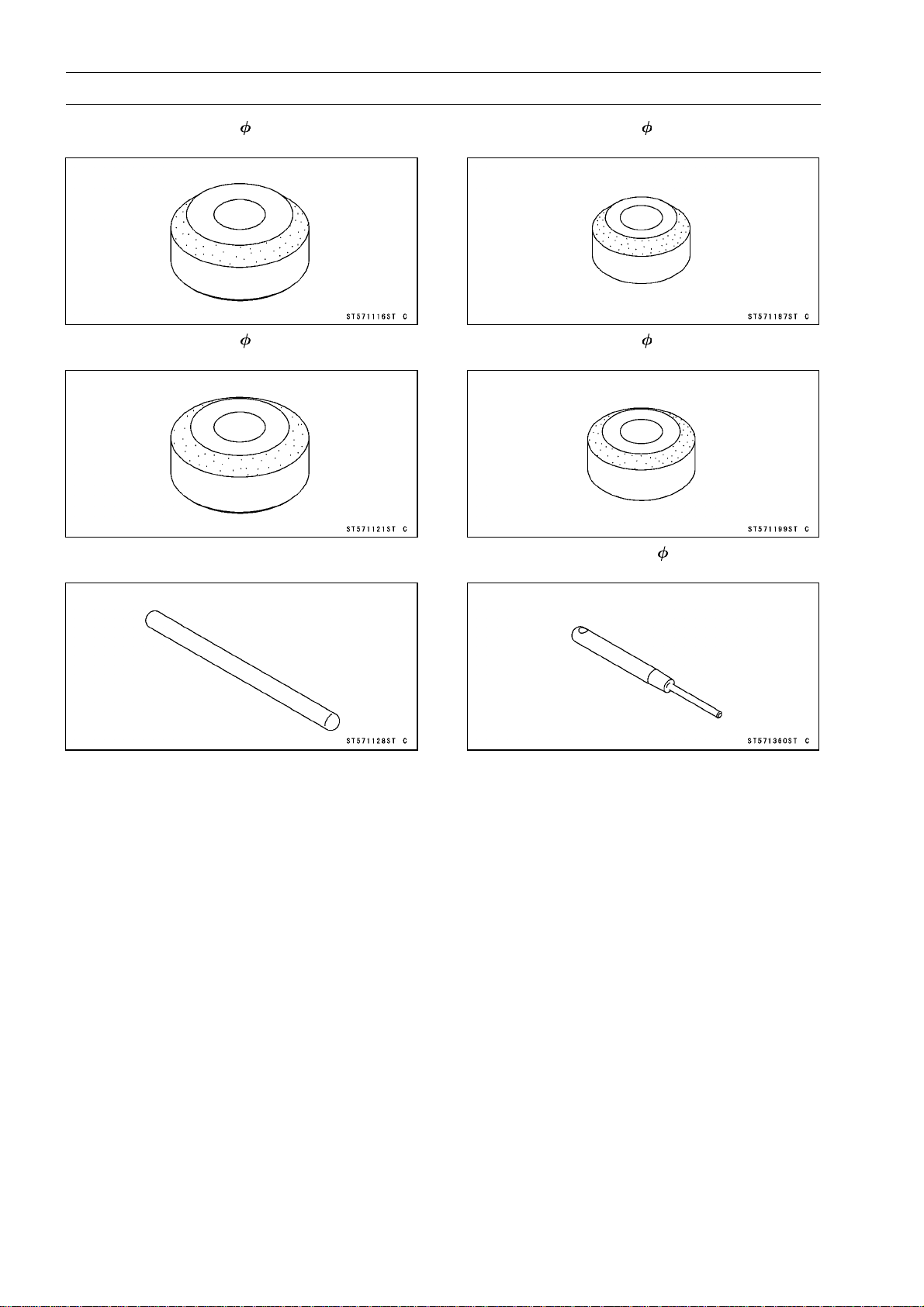
Valve Seat Cutter, 45° - 35:
57001-1116
Valve Seat Cutter, 32° - 35:
57001-1121
Valve Seat Cutter Holder Bar:
57001-1128
Valve Seat Cutter, 45° - 30:
57001-1187
Valve Seat Cutter, 32° - 33:
57001-1199
Valve Seat Cutter Holder, 6:
57001-1360
Page 23

Periodic Maintenance Procedures
Fuel System
NOTE
High and low idle speeds may vary depending on the
○
equipment on which the engine is used. Refer to the
equipment specification.
Low Idle Speed Adjustment
Disconnect all possible external loads from the engine.
•
Start the engine and warm it up thoroughly.
•
WARNING
Always keep your hands clear of the moving parts.
Move the throttle lever at a dash to the idle position.
•
Hold the throttle lever on the carburetor in closed position
•
(turn the governor arm clockwise all the way) and adjust
the low idle speed screw [A] until the engine idles at specified speed.
Low Idle Speed (Carburetor idle rpm)
1 4 50 r/min (rpm)
PERIODIC MAINTENANCE 2-7
Release the throttle lever.
•
Loosen the locknut [A].
•
Adjustthelow idlespeed set screw [B]on the controlplate
•
to obtain the specified governor low idle speed.
Low Idle Speed (Gover nor idle rpm)
1 5 50 r/min (rpm)
Tighten the locknut.
•
High Idle Speed Adjustment
NOTE
High idle speed adjustment should be made after the
○
idle speed adjustment is performed.
CAUTIO
Do not adjust high idle speed with the air cleaner
removed.
Start and warm up the engine thoroughly.
•
N
Page 24
2-8 PERIODIC MAINTENANCE
Periodic Maintenance Procedures
WARNING
Always keep your hands clear of the moving parts.
Loosen the locknut [A], and unscrew the high idle set
•
screw [B] few turns.
Movethethrottleleverondashtoobtainthe specified high
•
idle speed and leave it there.
High Idle Speed
3 600 r/min (rpm)
Turn the high idle set screw so that the end of it just
•
touches the speed control lever [C], and tighten the lock
nut.
Check the idle speed, and readjust the idle speed if nec-
•
essary.
CAUTION
Be sure to make the idle and fast idle speeds re-
spectively correspond to those of the equipment.
Fuel System Cleanliness Inspection
WARNING
Gasoline is extremely flammable and can be ex-
plosive under certain conditions. Turn the engine
switch OFF. Do not smoke. Make sure the area is
well-ventilated and free from any source of flame
or sparks; this includes any appliance with a pilot
light.
FX Models
Place a suitable container [A] under the drain screw [B]
•
on the carburetor.
Turn out the drain screw a few turns to drain the carbu-
•
retor and check if water or dirt has accumulated in the
carburetor.
Tighten the drain screw.
•
FR and FS Models
Place a suitable container under the carburetor.
•
Remove:
•
Solenoid Valve Connector [A]
Solenoid Valve [B]
Float Chamber [C] and Gasket
Check if water or dirt has accumulated in t he carburetor.
•
Install the removed parts (see appropriate chapters).
•
If any water or dirt is found, clean the carburetor (see
Carburetor Cleaning in the Fuel System chapter) and fuel
tank. And check the fuel filter (see Fuel Filter Inspection
in the Fuel System chapter).
Page 25

Periodic Maintenance Procedures
Element Cleaning and Inspection
Aircleanerelementsarenotrecommendedtobe cleaned,
and each air cleaner element should be replaced with new
ones at the maintenance time as shown in the maintenance
chart.
NOTE
Operating in dusty condition may require more frequent
○
maintenance than above.
FX Models
Remove the elements (see Element Removal in the Fuel
•
System chapter).
Replace the primary element [A] every 250 hrs.
•
PERIODIC MAINTENANCE 2-9
Replace the secondary element [A] with a new one if dirty
•
when primary element is checked.
Replace the secondary element every 500 hrs.
•
CAUTION
Do not wash air cleaner elements. Do not oil air
cleaner elements. Do not use pressurized air to
clean air cleaner elements.
FR Models
Remove the paper element (see Air Cleaner Element Re-
•
moval).
Clean the paper element [A] by tapping it gently on a flat
•
surface to remove dust. If the element is very dirty, re-
place it with a new one.
FS Models
Remove the foam and paper elements ( see Air Cleaner
•
Element Removal).
Clean the foam element [A] in a bath of detergent and
•
water, and let t he element air-dry thoroughly.
Clean the paper element [B] by tapping it gently on a flat
•
surface to remove dust. If the element is very dirty, re-
place it with a new one.
Page 26
2-10 PERIODIC MAINTENANCE
Periodic Maintenance Procedures
Air Cleaner H ousing (Cap and Body) Inspection
FX Models
Remove:
•
Elements (see E lement Removal in the Fuel System
chapter)
Air Cleaner Housing (see Air Cleaner Body and Bracket
Removal in the Fuel System chapter)
Clean the housing with detergent and water and dry the
•
housing thoroughly.
Check the housing for deformation or other damage.
•
Seal the housing well and permit only filtered air to reach
○
the carburetor.
Ifthehousing is damaged, replace thehousing with anew
one.
Check that no foreign material is obstructing the air pas-
•
sage.
Engine Top End
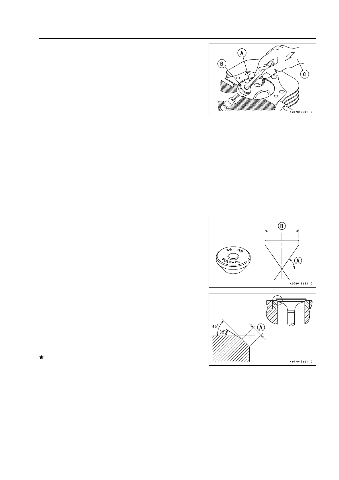
Cylinder Head Cleaning
Scrape the carbon deposits from the cylinder head and
•
the exhaust port with a suitable tool [A
To avoid gouging, use scrapers that are made of a m ate-
○
rial that will not cause damage.
Clean the head in a bath of high-flas
•
dry it with compressed air.
].
h point solvent and
WARNING
Clean the cylinder head in a well-ventilated area,
and take care that there are no sparks or flame anywhere near the working area; this includes any appliance with a pilot light. Do not use gasoline or a
low-flash point solvent to clean the cylinder head.
A fire or explosion could result.
Valve Clearance Inspection
NOTE
Valve clearance must be checked when the engine is
○
cold (at room temperature).
Remove the rocker covers (see Cylinder Head Assembly
•
Removal in the Engine Top End chapter).
Place the piston at the top dead center (TDC) of the com-
•
pressionstroke by turning the crankshaft clockwise facing
the flywheel.
Page 27
Periodic Maintenance Procedures
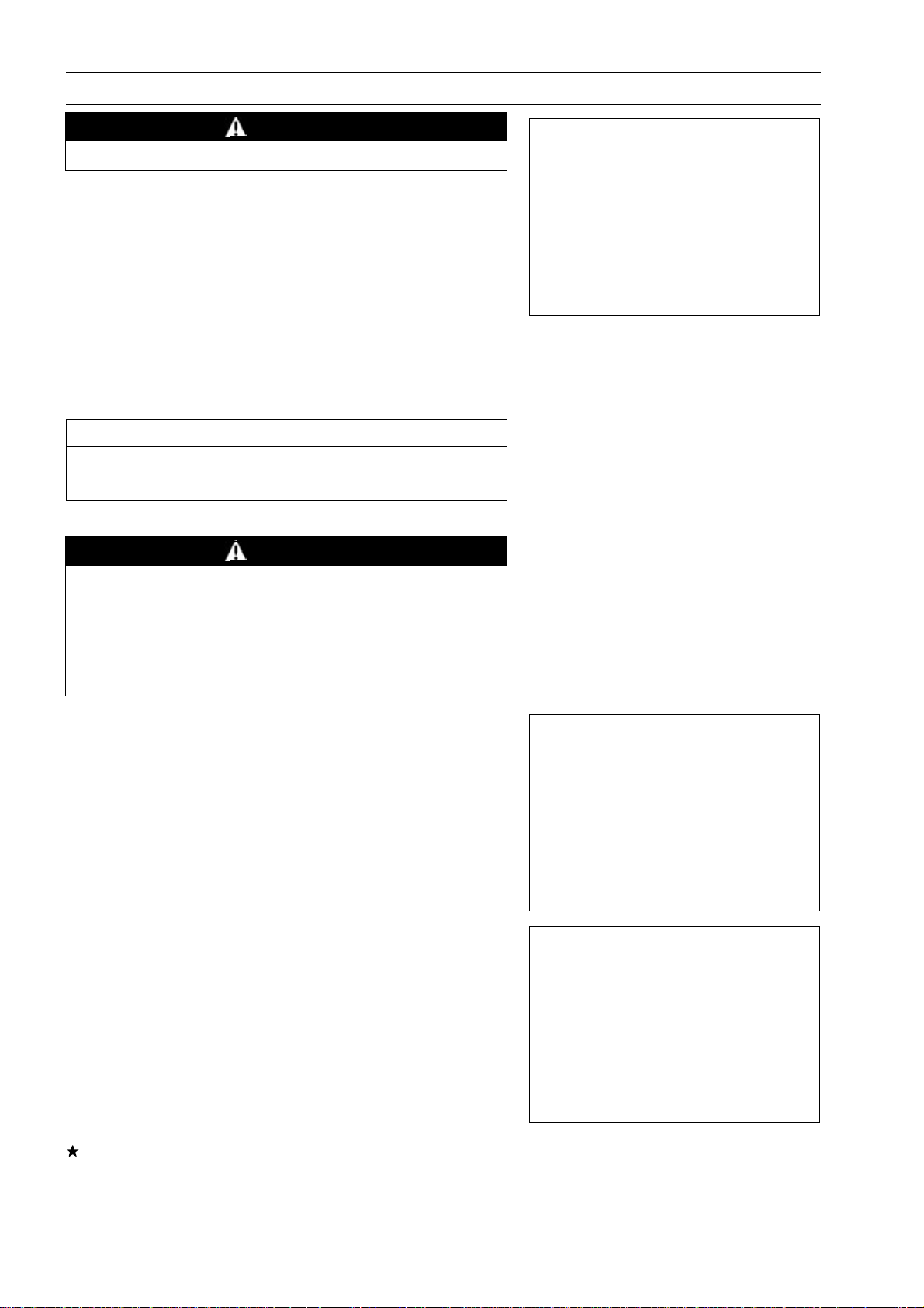
No.1 Cylinder
The left projection [A] on the flywheel is faced with the
○
right leg [B] on the #1 ignition coil [C] as shown in the
figure.
Checkthe inlet andexhaust valves are closed completely,
○
ifnot, turn the flywheel one turn(360°) clockwise and face
the left projection with the right leg again.
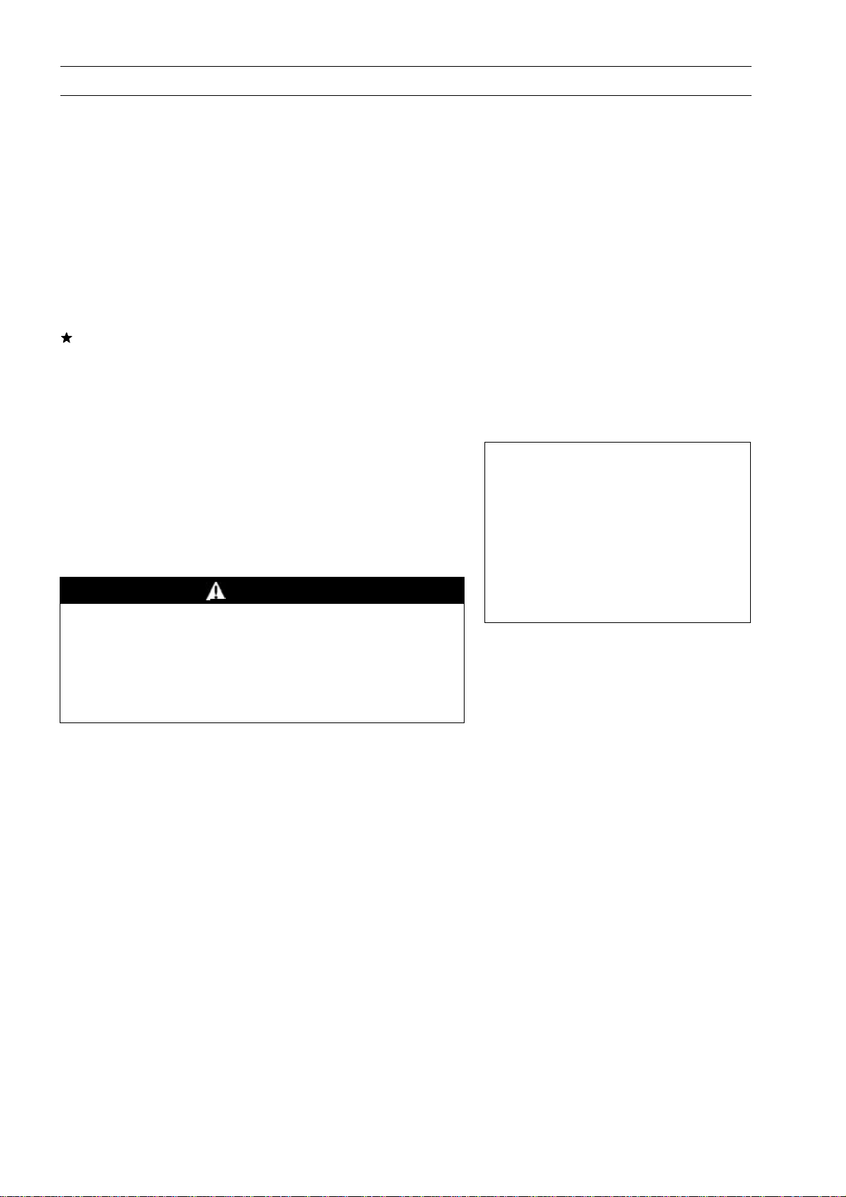
No.2 Cylinder
The left projection [A] on the flywheel is faced with the
○
right leg [B] on the #2 ignition coil [C] as shown in the
figure. Follow No.1 cylinder alignment.
PERIODIC MAINTENANCE 2-11
Then check the valve clearance.
•
Usingathicknessgauge[A],measurethe valveclearance
○
between the rocker arm [B] and the valve stem end.
If the valve clearance is incorrect, adjust it.
Valve Clearance (when cold)
Inlet, Exhaust 0.05 ∼ 0.10 mm (0.0020 ∼ 0.0039 in.)
Valve Clearance Adjustment
Since valve repairs change the valve clearance, adjust
•
the valve clearance to the specified.
Turnthecrankshaftin properdirection until the pistonis at
•
the TDC of the compression stroke (as described above).
Loosen the locknut [A] and adjusting bolt [B].
•
Insert a 0.05 mm (0.0020 in.) thickness gauge [C] be-
•
tween the rocker arm and valve stem end, and turn the
adjusting bolt until the thickness gauge begins to bind be-
tween the rocker arm and valve stem end. Sweep the
thickness gauge during this adjustment.
Valve Clearance (when cold)
Inlet, Exhaust:
0.05 ∼ 0.10 mm (0.0020 ∼ 0.0039 in.)
Page 28
2-12 PERIODIC MAINTENANCE
Periodic Maintenance Procedures
Holding the adjusting bolt with a spanner [A], tighten the
•
adjusting locknut [B] to the specified torque.
Torque - Valve Clearance Adjusting Locknuts: 11 N·m (1.1
kgf·m, 87 in·lb)
Donot overtighten the valve clearanceadjustinglocknuts.
•
After the valve clearance adjustment, measure the valve
•
clearance again. Readjust the valve clearance if necessary.
Valve Seat Inspection
Removethevalve(seeValveMechanismRemoval/Instal-
•
lation in the Engine Top End chapter).
Inspect the valve seats for damage.
•
If the seats are warped or distorted beyond reconditioning, replace the cylinder head with a new one.
Pitted or worn valve seats can be refaced. Lap the valves
•
to the seats after refacing.
Coat the valve seat with machinist’s dye.
•
Push the valve into the guide.
•
Rotate the valve against the seat with a lapping tool.
•
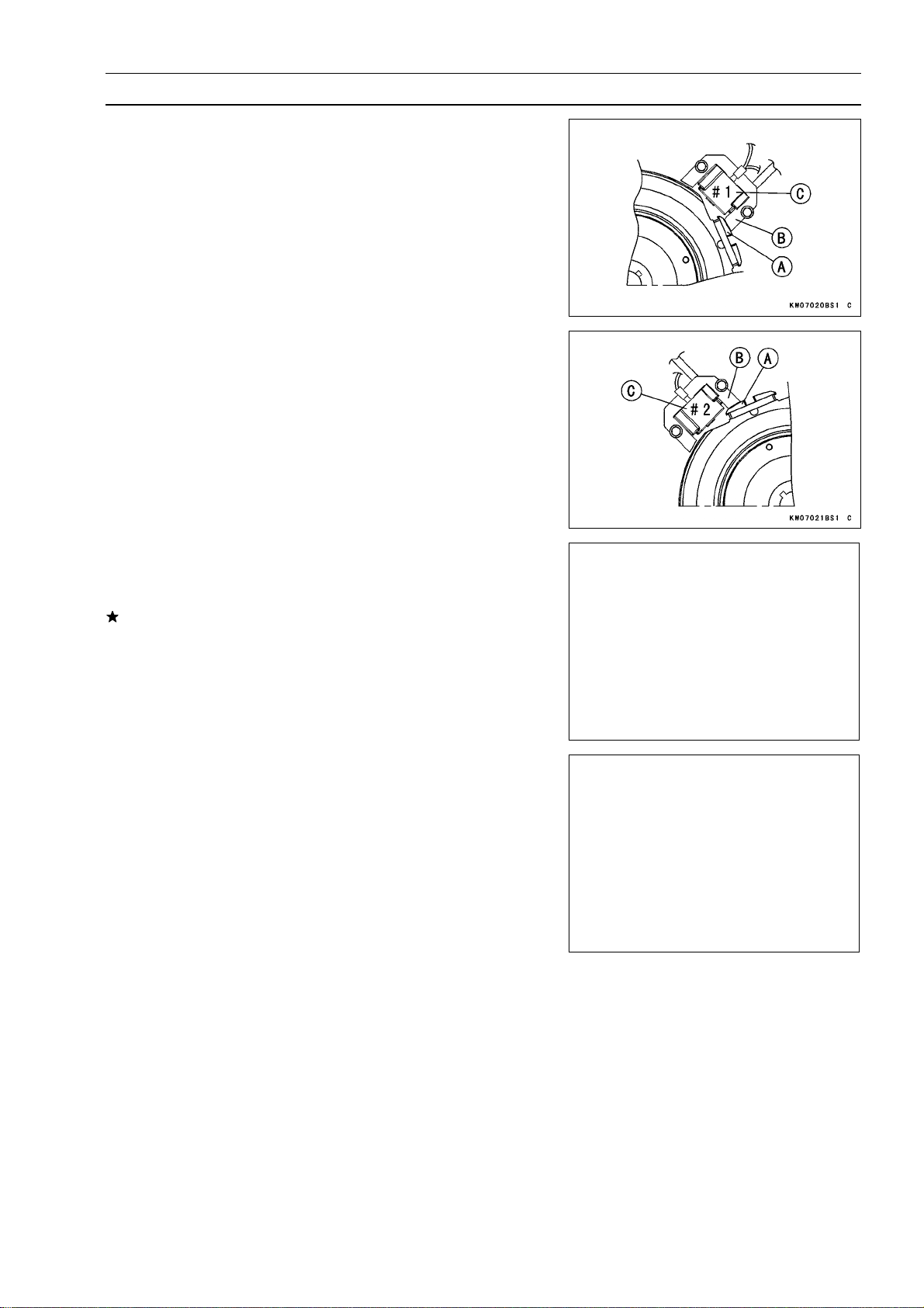
Pull the valve out, and check the seating pattern on the
•
valve head. It must be the correct width [A] and even all
the way around.
NOTE
The valve stem and guide must be in good condition or
○
this check w ill not be valid.
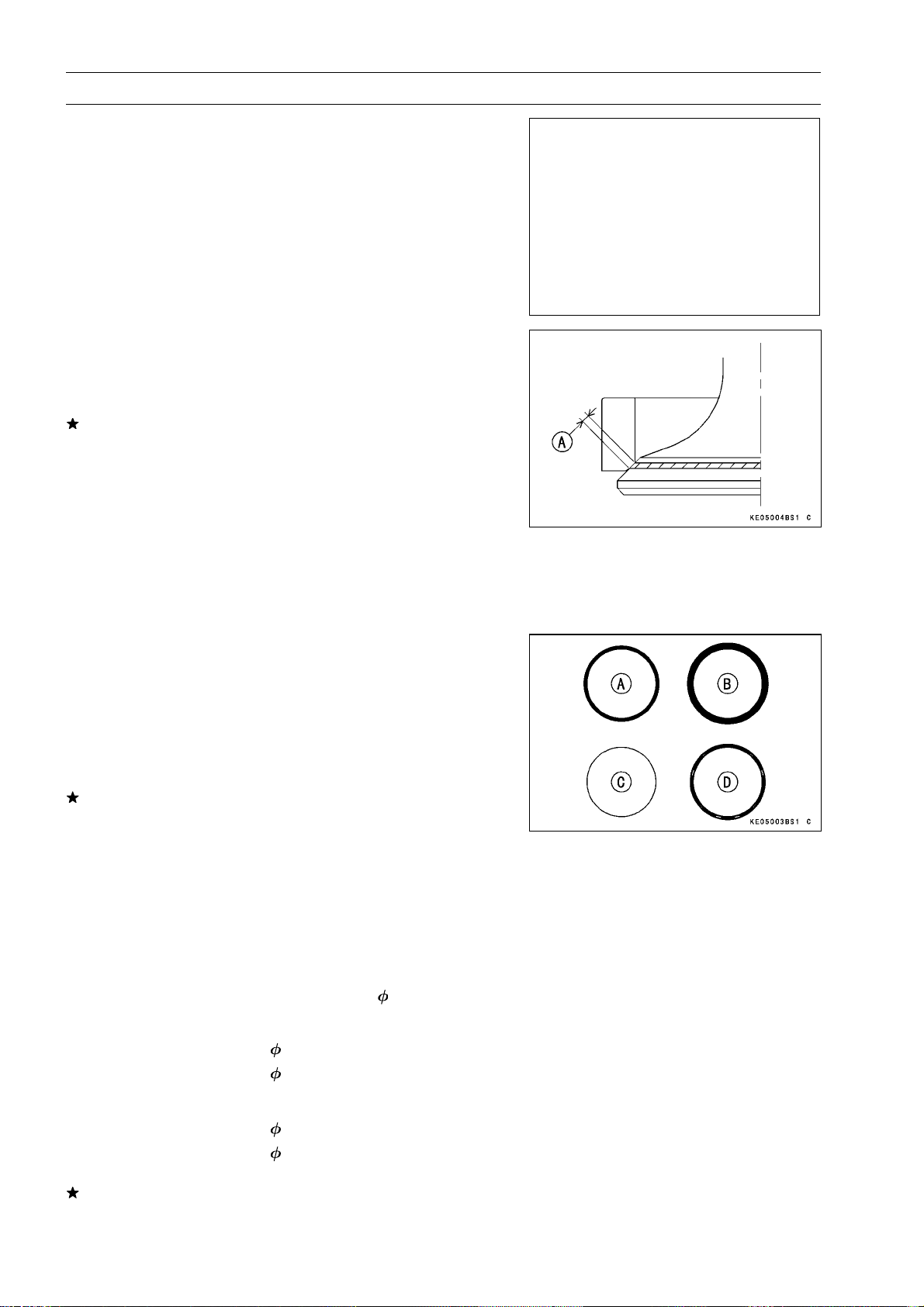
Good [A]
TooWide[B]
Too Narrow [C]
Uneven [D]
If the valve seating pattern is not correct, repair the seat.
Valve Seating Surface Width (STD)
Exhaust
Inlet
Valve Seat Repair
Followthemanufacture’sinstructionsforuse of valve seat
•
cutters.
Special Tools-Valve Seat Cutter Holder Bar: 57001-1128
Exhaust Valve
Valve Seat Cutter, 45° Valve Seat Cutter, 32° -
0.8 ∼ 1.6 mm (0.039 ∼ 0.059 in.)
1.2 ∼ 1.8 mm (0.043 ∼ 0.067 in.)
Valve Seat Cutter Holder,
30: 57001-1187
33: 57001-1199
6: 57001-1360
Inlet Valve
Valve Seat Cutter, 45° Valve Seat Cutter, 32° -
Ifthe manufacture’s instructions are not available, use the
following procedure.
35: 57001-1116
35: 57001-1121
Page 29
Periodic Maintenance Procedures
Seat Cutter Operating Cares
1. This valve seat cutter is designed only for valve seat
repair. Therefore the cutter must not be used for other
purposes.
2. Do not drop or hit the valve seat cutter, or the diamond
particles may fall off.
3. Do not fail to apply engine oil to the valve seat cutter
before grinding the seat surface. Also wash off ground
particles sticking to the cutter with washing oil.
NOTE
Do not use a wire brush to remove the metal particles
○
from the cutter. It will take off the diamond particles.
4. Setting the valve seat cutter holder [A] in position, op-
erate the cutter [B] with one hand [C]. Do not apply too
much force to the diamond portion.
NOTE
Prior to grinding, apply engine oil to the cutter, and dur-
○
ing the operation wash off any ground particles sticking
to the cutter with washing oil.
PERIODIC MAINTENANCE 2-13
5. After use wash the cutter with washing oil and apply a
thin layer of engine oil before storing.
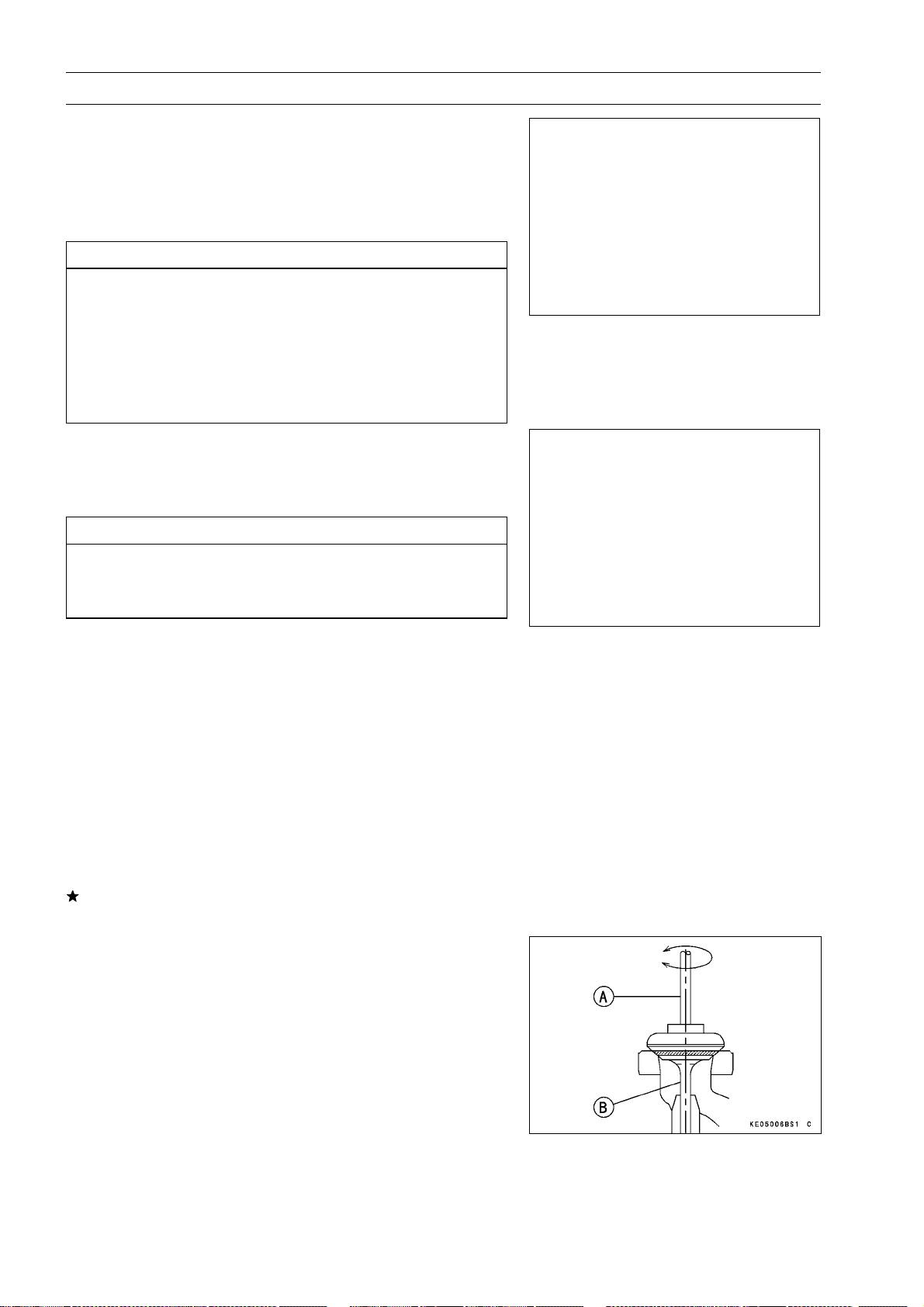
Marks Stamped on the Cutter
The marks stamped on the back of the cutter represent the
following.
32° Cutter angle [A]
37.5 Cutter diameter [B]
KS8B Manufactured lot number
Operating Procedures
Clean the seat area carefully.
•
Recondition the valve seats with the valve seat cutters
•
(45°, 32°) and lap the valves.
Check the seats for good contact all the way around with
•
machinist’s dye.
Measure the seat width [A]. If it is more than the standard
•
width, the seating surface should be r efaced.
If the valve seating pattern is not correct, repair the seat.
Page 30
2-14 PERIODIC MAINTENANCE
Periodic Maintenance Procedures
Coat the seat with machinist’s dye.
•
Fit a 45° cutter [A] to the holder and slide it into the valve
•
guide.
Resurface the valve seat with a 45° cutter, removing only
○
enough material to produce a smooth and concentric
seat.
CAUTION
Do not grind the seat too much. Overgrinding will
reduce valve clearance by sinking the valve into the
head. If the valve sinks too far into the head, it will
beimpossible to adjust the clearance, and the cylinder head must be replaced. Do not turn the cutter
counterclockwise or drop it against the seat, or it
will be dulled.
Use a 32° seat cutter [A] to narrow the seat width to the
•
standard width.
Turntheseatcutteroneturnatatimewhile pressingdown
○
very lightly. Check the seat width after each turn.
CAUTION
The 32° cutter removes material very quickly.
Check the seat width frequently to prevent over
grinding.
NOTE
Keepthe seat width as closeas possible to thestandard
○
width.
Make a light contact on the valve seat with the 45° cutter
•
to remove any possible burrs at the edge of the seat.
After resurfacing the seat, inspect for even valve seating.
•
Apply a m achinist’s dye to the valve face, insert the
○
valve, and snap it closed against the seat several times.
The valve surface should show good contact all the way
around. Be sure the valve seat is centered on the valve
face. The position of the valve in the seat is evident after
lapping the valve.
If the seat does not make proper contact, lap the valve
into seat with a lapper.
Coat the face of valve sparingly with a fine lapping com-
•
pound.
Use the lappingtool [A], to grip top of the valve [B]. Rotate
•
the valve in a circular motion to lap the valve to the seat.
Lift the valve slightly from the seat every 8 to 10 strokes,
•
continue lapping operation until a uniform ring appears
around entire surface of the valve face.
Page 31

Periodic Maintenance Procedures
When lapping is completed, wash all parts in solvent to
•
remove lapping compound. Dry the parts thoroughly.
Note the position of the lapping mark on the valve face.
•
The lapping mark should appear on or near the center of
the valve face.
Whentheengineisassembled, be suretoadjustthevalve
•
clearances (see Valve Clearance Adjustment).
Lubrication System
Engine Oil Level Inspection
Place the engine on a level surface.
•
Remove the oil filler cap [A] and wipe its dipstick [B] with
•
a clean cloth.
Insert the dipstick into tube [C] without screwing it in, then
•
check the oil level.
The oil level should be the operating range (grid area) [D]
•
on the dipstick.
If the oil level is “ADD” range [E], add enough engine oil
to bring oil level to the operating range.
PERIODIC MAINTENANCE 2-15
CAUTION
Do not add more oil above the operating range. Ex-
cess oil will cause a smoking condition.
Use the same type and make of oil that is already in the
○
engine.
NOTE
If the engine oil type and make are unknown, use any
○
brandofthespecifiedoiltotopup the level in preference
to running the engine with the oil level low. Then at your
earliest convenience, change the oil completely.
If the oil level is “FULL” range [F], drain the ex
loosening the drain plug.
Engine Oil Change
Change the oil after first 8 hours of operation. Thereafter
•
change oil every 100 hours.
Start and warm up the engine to drain the oil easily.
•
Stop the engine.
•
Place the engine on a level surface.
•
Place a suitable container under the engine.
•
Remove the oil drain plug [A] and drain the oil.
•
WARNING
cess oil by
Be careful of hot oil when draining. It may be hot
enough to burn you severely.
Replace the O-ring [B] with a new one.
•
Apply grease to the O-ring.
•
Install the oil drain plug with the O-ring and tighten it.
•
Torque - Engine Oil Drain Plug: 6.9 N·m (0.70 kgf·m, 61
in·lb)
Page 32

2-16 PERIODIC MAINTENANCE
Periodic Maintenance Procedures
Remove the oil filler cap and pour in the specified type
•
and the amount of oil.
Engine Oil:
Grade: SF , SG, SH, SJ or SL Class
Viscosity:
Capacity: [When the oil filter is not removed]
Check the O-ring [A] on the oil filler cap for damage. Re-
•
place the oil filler cap assembly if O-ring is damaged.
When checking the oil level, do not turn oil filler cap on
threads.
Some increase in oil consumption may be expected
○
whena multi grade engine oil(10W-30/10W-40, 5W-20)
isused. Check the oil levelmore frequently than recommended interval.
SAE40, SAE30, SAE10W-30/SAE10W-40,
or SAE5W-20
1.8 L (1.9 US qt)
[When the oil filter is removed]
2.1 L (2.2 US qt)
NOTE
Oil Filter Replacement
Drain the engine oil (see Engine Oil Change).
•
Using a suitable tool [A], remove the oil filter [B].
•
When unscrewing the oil filter, place a suitable container
○
beneaththe oil drip tray to receive oil from the oil filter and
oil passages in the engine.
Replace the oil filter [A] with a new one.
•
Apply light film of engine oil to the seal [B].
•
Install the oil filter.
•
Turnthe filter until the seal contacts mounting surface [C]
○
of the engine. Then turn the filter BY HAND (S) 3/4 turn.
Run the engine at slow idle speed 3 minutes.
•
While running the engine, check for oil leaks around it.
○
Stop the engine and check the oil level (see Engine Oil
•
Level Inspection).
Page 33

Periodic Maintenance Procedures
Electrical System
Spark Plug Cleaning and Inspection
Carefully pull the plug cap from the spark plug, and re-
•
move the spark plug.
If the plug is oily or has carbon built up on it, clean the
plug using a high-flash point solvent and a wire brush or
other suitable tools.
If the spark plug electrodes are corroded or damaged, or
ifthe insulator is cracked replace the plugwith a new one.
Use the standard spark plug or its equivalent.
Insulator [A]
Center Electrode [B]
Plug Gap [C]
Side Electrode [D]
Spark Plug Gap Inspection
Measure the gap w ith a wire-type thickness gauge.
•
If the gap is not correct, carefully bend the side electrode
with a suitable tool to obtain the correct gap.
PERIODIC MAINTENANCE 2-17
Spark Plug Gap
Standard: 0.7 ∼ 0.8 mm (0.028 ∼ 0.031 in.)
Page 34

Page 35

FUEL SYSTEM 3-1
Fuel System
Table of Contents
Exploded View........................................................................................................................ 3-2
Specifications ......................................................................................................................... 3-8
Governor Link Mechanism...................................................................................................... 3-10
Control Panel Assembly Removal .................................................................................... 3-10
Control Panel Assembly Installation ................................................................................. 3-10
Governor Arm Removal.................................................................................................... 3-11
Governor Arm Installation................................................................................................. 3-12
Governor Assembly Removal ........................................................................................... 3-12
Governor Assembly Installation ........................................................................................ 3-13
Governor Assembly Inspection......................................................................................... 3-13
Governor Shaft Removal .................................................................................................. 3-13
Governor Shaft Installation ............................................................................................... 3-13
Carburetor .............................................................................................................................. 3-14
Fuel and Air Flow.............................................................................................................. 3-14
Fuel Shut Off Solenoid Valve............................................................................................ 3-17
Low Idle Speed Adjustment.............................................................................................. 3-17
High Idle Speed Adjustment ............................................................................................. 3-17
High Altitude Operation..................................................................................................... 3-17
Main Jet Replacement ...................................................................................................... 3-18
Fuel System Cleanliness Inspection................................................................................. 3-19
Inlet Pipe Removal............................................................................................................ 3-20
Inlet Pipe Installation......................................................................................................... 3-20
Carburetor Removal.......................................................................................................... 3-21
Carburetor Installation....................................................................................................... 3-23
Carburetor Disassembly/Assembly................................................................................... 3-25
Carburetor Cleaning.......................................................................................................... 3-28
Carburetor Inspection ....................................................................................................... 3-29
Fuel Shut Off Solenoid Valve Test .................................................................................... 3-30
Inlet Manifold .......................................................................................................................... 3-31
Inlet Manifold Removal ..................................................................................................... 3-31
Inlet Manifold Installation .................................................................................................. 3-31
Inlet Manifold Inspection................................................................................................... 3-32
Fuel Pump, Fuel Filter............................................................................................................ 3-33
Fuel Pump Removal ......................................................................................................... 3-33
Fuel Pump Installation...................................................................................................... 3-33
Fuel Pump Inspection....................................................................................................... 3-33
Fuel Filter Removal/Installation......................................................................................... 3-34
Fuel Filter Inspection......................................................................................................... 3-34
Air Cleaner.............................................................................................................................. 3-35
Element Removal.............................................................................................................. 3-35
Element Installation........................................................................................................... 3-36
Element Cleaning and Inspection..................................................................................... 3-37
Air Cleaner Body and Bracket Removal ........................................................................... 3-37
Air Cleaner Body and Bracket Installation ........................................................................ 3-38
Air Cleaner Housing (Cap and Body) Inspection.............................................................. 3-38
3
Page 36

3-2 FUEL SYSTEM
Exploded View
FX M odels
Page 37

Exploded View
FUEL SYSTEM 3-3
No. Fastener
1 Air Cleaner Bracket Mounting Bolts 5.9 0.60 52 in·lb
2 Air Cleaner Holder Bracket Bolts 5.9 0.60 52 in·lb
3 Carburetor and Inlet Pipe Mounting Bolts 5.9 0.60 52 in·lb
4 Carburetor and Inlet Pipe Mounting Nuts 5.9 0.60 52 in·lb
5 C hoke Valve Screws 0.93 0.095 8.2 in·lb
6 Cover Plate Screw 2.4 0.24 21 in·lb
7 Drain Screw 2.0 0.20 18 in·lb
8 Float Chamber Mounting Screws 3.9 0.40 35 in·lb
9
Inlet Manifold Bolts
10
Throttle Valve Screws
R: Replacement Parts
S: Tighten the fasteners following the specified sequence.
N·m kgf·m ft·lb
5.9 0.60 52 in·lb
0.93 0.095 8.2 in·lb
Torque
Remarks
S
Page 38

3-4 FUEL SYSTEM
Exploded View
FR651V, FR691V, FR730V, FS651V, FS691V, F S730V Models
Page 39

Exploded View
FUEL SYSTEM 3-5
No. Fastener
1 Carburetor and Inlet Pipe Mounting Nuts 5.9 0.60 52 in·lb
2 Control Panel and Inlet Pipe Mounting Bolt 5.9 0.60 52 in·lb
3 Inlet Manifold Bolts 5.9 0.60 52 in·lb S
4 Main Jet 2.3 0.23 20 in·lb
5 Solenoid Valve 4.5 0.46 40 in·lb
Throttle Lever Mounting Screw (FR651V,
6
FR691V, FS651V, FS691V Models)
7 Throttle Valve Screws 0.68 0.069 6.0 in·lb L
8. FR730V and FS730V Models
9. FS Models
L: Apply a non-permanent locking agent.
R: Replacement Parts
S: Tighten the fasteners following the specified sequence.
N·m kgf·m ft·lb
0.68 0.069 6.0 in·lb L
Torque
Remarks
Page 40

3-6 FUEL SYSTEM
Exploded View
Page 41

Exploded View
FUEL SYSTEM 3-7
No. Fastener
N·m kgf·m ft·lb
1 Control Panel Mounting Bolt 5.9 0.60 52 in·lb
2 Governor Arm Clamp Nut 7.8 0.80 69 in·lb
3 Governor Arm Joint Bolt 5.9 0.60 52 in·lb Lh
4 Governor Shaft Plate Screws 2.0 0.20 18 in·lb
5. FR and FS Models
EO: Apply engine oil.
Lh: Left-hand threads.
R: Replacement Parts
Torque
Remarks
Page 42

3-8 FUEL SYSTEM
Specifications
Item Standard
Carburetor Specifications:
Make/Type:
FR651V and FS651V Walbro/LMF-23
FR691V and FS691V Walbro/LMF-26
FR730V and FS730V Walbro/LMF-22
FX651V Nikki 621266-A61
FX691V Nikki 621266-A51
FX730V Nikki 621266-A01
Throttle Bore Diameter:
FR and FS Models 30 mm (1.18 in.)
FX Models
Venturi Diameter:
FR and FS Models 22 mm (0.87 in.)
FX Models
Main Jet (MJ):
FR and FS Models #124
FX Models L: #110
Pilot Jet (PJ):
FR and FS Models #56
FX Models
Pilot Air Screw Turns out (PS) (Idle
Mixture Screw Turns Out):
FR and FS Models 1 1/4 ± 1/2
FX Models 21/2
Float Level Float parallel to carburetor body
Idle Speed: (1)
Low Idle Speed (Carburetor idle rpm) 1 450 r/min (rpm)
Low Idle Speed (Governor idle rpm) 1 550 r/min (rpm)
High Idle Speed 3 600 r/min (rpm)
Air Cleaner:
Type:
FR Models Single stage filtration system
FS and FX Models D ual stage filtration system
Pre-cleaner:
FR Models Paper element
FS Models Foam element
FX Models Paper element
Second-stage cleaner:
FS Models Paper element
FX Models Foam element
26 mm (1.02 in.)
20 mm (0.79 in.)
R: #114
#60
Page 43

FUEL SYSTEM 3-9
Specifications
Fuel (2)
Fuel Requirement Unleaded regular grade gasoline
US, Canada Using a minimum of 87 octane by antiknock index is
recommended.
Antiknock Index: (RON + MON)/2
RON = Research Octane Number
MON = Motor Octane Number
Other Countries Using a minimum of 91 octane by RON is recommended.
Fuel Pump
Type Pulse-diaphragm pump
Governor
Type Flyweight all speed governor
(1) Idle speeds may vary depending on each equipment. Refer to the equipment specification.
(2) Other fuel requirements:
See Fuel and oil recommendations in Owner’s Manual.
Page 44

3-10 FUEL SYSTEM
Governor Link Mechanism
Control Panel Assembly Removal
FX Models
Remove:
•
Inlet Pipe Mounting Bolt [A] and Nut [B]
Control Panel M ounting Bolt [C]
Choke Spring [D]
Control Panel Assembly [E]
Governor Spring [F]
FR and FS Models
Remove:
•
Control Panel and Inlet Pipe Mounting Bolt [A]
Carburetor and Inlet Pipe Mounting Nut [B]
Control Panel M ounting Bolt [C]
Choke Spring [D]
Control Panel Assembly [E]
Governor Spring [F]
Control Panel Assembly Installation
Before installing the contr
•
thatthe choke lever [A] and engine speed control lever [B]
move smoothly in all directions.
If any part is worn or dama
assembly with a new one.
FX Models [C]
FR and FS Models [D]
FX Models
Install the governor spring [A], control panel assembly [B]
•
and choke spring [C].
Tighten:
•
Torque - Control Panel Mounting Bolt [D]: 5.9 N·m (0.60
kgf·m, 52 in·lb)
Carburetor and Inlet Pipe Mounting Nut [E]: 5.9
N·m (0.60 kgf·m, 52 in·lb)
Carburetor and Inlet Pipe Mounting Bolt [F]: 5.9
N·m (0.60 kgf·m, 52 in·lb)
After installation, adjust the low idle speed and high idle
•
speed to the specifications (see Low/High Idle Speed Adjustment in the Periodic Maintenance chapter).
ol panel assembly,check to see
ged, replace the control panel
Page 45

Governor Link Mechanism
FR and FS Models
Install the governor spring [A], control panel assembly [B]
•
and choke spring [C].
Tighten:
•
Torque - Control Panel Mounting Bolt [D]: 5.9 N·m (0.60
kgf·m, 52 in·lb)
Carburetor and Inlet Pipe Mounting Nut [E]: 5.9
N·m (0.60 kgf·m, 52 in·lb)
Control Panel and Inlet Pipe Mounting Bolt [F]: 5.9
N·m (0.60 kgf·m, 52 in·lb)
After installation, adjust the low idle speed and high idle
•
speed to the specifications (see Low/High Idle Speed Adjustment in the Periodic Maintenance chapter).
Governor Arm Removal
Remove the control panel assembly (see Control Panel
•
Assembly Removal)
Unhook the throttle link rod spring [A] end loop and clear
•
the throttle link rod lower end [B].
FX Models [C]
FR and FS Models [D]
FUEL SYSTEM 3-11
Loosen the clamp nut [A] and take off the governor arm
•
[B].
Page 46

3-12 FUEL SYSTEM
Governor Link Mechanism
Remove the bolt [A] to separate the governor arms [B].
•
Governor Arm Installation
Installthe inside governor arm [A] onto the governor shaft
•
[B].
Be sure the link spring [C] around the throttle link rod [D]
•
is in place and that it pulls the outside governor arm [E]
and throttle lever [F] each other.
Tighten:
•
Torque - Governor Arm Clamp Nut [G]: 7.8 N·m (0.80 kgf·m,
69 in·lb)
Turnthe top end of the governor arm countercl
•
fully open the carburetor throttle valve and hold it there.
Turntheinside governor arm counterclockwise fully tothe
•
end of its travel.
Tighten:
•
Torque - Governor Arm Joint Bolt [H]: 5.9 N·m (0.60 kgf·m,
52 in·lb)
Governor arm joint bolt is left-hand threads.
○
Install the control panel assembly (see Control Panel As-
•
sembly Installation).
ockwise to
Governor Assembl
Remove:
•
Camshaft (see Camshaft, Tappet Removal in the
Camshaft/Crank
Pin [A]
Washer (
Snap Rings [C]
Washer (
Sleeve [E]
Governor Plate [F]
Steel Balls [G]
Ball Guide [H]
Ball Plate [I]
30) [B]
42) [D]
y Removal
shaft chapter)
Page 47

Governor Link Mechanism
Governor Assembly Installation
Fit the snap ring into the groove securely.
•
Turn the governor plate by hand and check that the steel
•
balls and governor plate operate freely.
Replace the spring pin [A] with a new one.
•
Be sure to install the washer [B] and pin.
•
2.0 ∼ 2.3 mm (0.079 ∼ 0.091 in.) [C]
Governor Assembly Inspection
Visually check all governor parts for wear or damage.
•
If any parts are worn or damaged, replace them with new
ones.
Governor Shaft Removal
Remove the crankcase cover (see Crankcase Cover Re-
•
moval in the Camshaft/Crankcase chapter).
Unscrew the governor shaft plate screws [A], and remove
•
the governor shaft plate [B].
Pull out the governor shaft [C] outside.
•
NOTE
Remove the governor shaft only if the replacement of
○
the governor shaft is necessary.
FUEL SYSTEM 3-13
Replace the oil seal with a new one if the lip shows signs
•
ofleakage or it has been dam aged (see Crankcase Cover
Assembly in the Camshaft/Crankshaft chapter).
Governor Shaft Installation
Apply engine oil to the governor shaft.
•
Insert the governor shaft [A] into the crankcase cover.
•
Install the governor shaft plate [B] to the shaft.
•
Tighten:
•
T orque - Governor Shaft Plate Screws [C]: 2.0 N·m (0.20
kgf·m, 18 in·lb)
eckthatthegovernorshaftmovesfreelyinitsoperating
Ch
•
range.
NOTE
If the oil seal is removed, oil seal is put on after shaft
○
is installed (see Crankcase Cover Installation in the
Camshaft/Crankshaft chapter).
Page 48

3-14 FUEL SYSTEM
Carburetor
Fuel and Air Flow
FX Models
The main system of the carburetor consists of the main jet [A], valve seat [B], main nozzle [C], and
the main air passage [D] (main air jet [E]). The main system meters fuel to the engine during m oderate
to heavy load conditions. Fuel flows through the main jet and into the main nozzle, where it is joined
by air from the main air passage (main air orifice). The resulting mixture flows out the end of the main
nozzle into t he carburetor bore, where it is atomized by the high speed air flow, and carried into the
engine.
Page 49

FUEL SYSTEM 3-15
Carburetor
The pilot system includes the pilot jet [F], pilot screw [G] (Idle mixture screw), pilot outlet [H], and
the bypass holes [I]. The pilot system meters the fuel/air mixture while the engine is idling and running
under a light load. Under these conditions there is very little air flow through the carburetor bore;
so little that it is not enough to draw fuel through the main system of the carburetor and atomize it.
Instead, the fuel is drawn through the pilot system, since the nearly closed throttle valve [J] causes
high speed air flow past the pilot outlet and bypass holes (even at low engine speed).
Fuel flow in the pilot system is metered by the pilot jet. Air for better atomization is admitted via the
pilot air jet in the mouth of the carburetor. The fuel/air mixture passes into the bore of the carburetor
side stream of the throttle valve through the bypass holes and pilot outlet. While the throttle valve is
almost closed, it covers the small bypass holes opening into the bore from the pilot system. As the
throttle valve begins to open, it uncovers the bypass holes, allowing more fuel/air mixture to flow. The
extra flow is needed because the engine starts to run f aster as the throttle is opened. The pilot screw
controls the amount of fuel/air mixture allowed through the pilot outlet, but does not meter the bypass
holes. A moderate amount of air comes in around the throttle valve at an idle, so adjusting the pilot
screw changes the fuel/air ratio. Turning the pilot screw (Idle mixture screw) out (Counterclockwise)
enrichens the mixture; turning it in (clockwise) leans the mixture.
Page 50

3-16 FUEL SYSTEM
Carburetor
FR and FS Models
The main system of the carburetor consists of the main
jet [A], main nozzle [B], and the main air passage [C] (main
air jet [D]). The main system meters fuel to the engine during moderate to heavy load conditions. Fuel flows through
the main jet and into the main nozzle, where it is joined by
air from the m ain air passage (main air jet). The resulting
mixture flows out the end of the main nozzle into the carburetor bore, where it is atomized by the high speed air flow,
and carried into the engine.
The pilot system includes the pilot jet [E], pilot screw [F]
(idle mixture screw), pilot air jet [G], pilot outlet [H], and the
bypassholes[I].The pilot system meters the fuel/airmixture
while the engine is idling and running under a light load.
Under these conditions there is very little air flow through
thecarburetor bore; so littlethat it is not enough to draw fuel
through the main system of the carburetor and atomize it.
Instead, the fuel isdrawn through thepilot system, sincethe
nearly closed throttle valve [J] causes high speed air flow
past the pilot outlet and bypass holes (even at low engine
speed).
Fuel flow in the pilot system is metered by the pilot jet. Air
for better atomization is admitted via the pilot air jet in the
mouth of the carburetor. The fuel/air mixture passes into
the bore of the carburetor side stream of the throttle valve
through the bypass holes and pilot outlet. While the throttle valve is almost closed, it covers the small bypass holes
opening into the bore from the pilot system. As the throttle
valve begins to open, it uncovers the bypass holes, allowing more fuel/air mixture to flow. The extra flow is needed
because the engine starts to run faster as the throttle is
opened. The pilot screw controls the amount of fuel/air
mixture allowed through the pilot outlet, but does not meter the bypass holes. A moderate amount of air comes in
around the throttle valve at idle, so adjusting the pilot screw
changes the fuel/air ratio. Turning the pilot screw (idle mixture screw) out (counterclockwise) enriches the mixture;
turning it in (clockwise) leans the mixture.
Main Fuel Flow →
Pilot Fuel Flow ⇒
Page 51

Carburetor
Fuel Shut Off Solenoid Valve
To avoid after firing when stopping the engine, a solenoid
actuated fuel shut off solenoid valve [A] is installed in the
carburetor bowl. The valve shuts off the fuel supply to the
main jets [B] simultaneously when the switch key turned to
the “OFF” position.
The valve opens automatically when the switch key is
turned to the “Run” position.
FX Models [C]
FR and FS Models [D]
FUEL SYSTEM 3-17
Low Idle Speed Adjustment
Refer to the Low Idle Speed Adjustment in the Periodic
•
Maintenance chapter.
High Idle Speed Adjustment
Refer to the High Idle Speed Adjustment in the Periodic
•
Maintenance chapter.
High Altitude Operation
At high altitude, the standard carburetor air-fuel mixture
will be excessively rich. Performance will decrease, and
fuel consumption will increase. High altitude performance
can be improved by installing a smaller diameter main-jet in
the carburetor and adjusting the idle speed.
NOTE
The main jet high altitude kits are available if the equip-
○
ment is to be used in the high altitude. The main jet
numbers are stamped on the ends of the main jets.
High Altitude Main Jet
Altitude
0 ∼ 1000m(0∼ 3000ft) #124
1 000 ∼ 2000m(3000∼ 6
000 ft)
2 000 m (6 000 ft) and
higher
Main Jet No.
FR/FS FX
L: #110
R: #114
#122
#120
L: #107
R: #111
L: #104
R: #108
Page 52

3-18 FUEL SYSTEM
Carburetor
Main Jet Replacement
FX Models
Close the fuel shut off valve in the equipment.
•
Remove the carburetor (see Carburetor Removal).
•
Drain the fuel in the carburetor completely by unscrewing
•
the drain screw at the bottom of the float chamber (see
Fuel System Cleanliness Inspection in the Periodic Maintenance chapter).
Unscrew the chamber screws [A] and take off the float
•
chamber [B].
Remove the float assembly [A] from the float chamber.
•
Remove:
•
Pin [A]
Float [B]
Float Valve [C]
Spacer [D]
O-rings [E]
Use the rod to push the main jet “L” [A] and “R” [B] out
•
from the bottom side of the spacer [C].
Page 53

Carburetor
Replace the main jet [A] with a new one for altitude ex-
•
pected (see High Altitude Operation).
Install the new O-ring [B] to the main jet.
•
Usingthe suitable rod [C], press the main jet until they are
•
bottomed to the spacer [D].
Assemble the carburetor (see Carburetor Disassem-
•
bly/Assembly).
FUEL SYSTEM 3-19
FR and FS Models
Close the fuel shut off valve in the equipment.
•
Remove the carburetor (see Carburetor Removal).
•
Unscrew the solenoid valve [A] and take off the float
•
chamber [B] and gasket.
Using a properly sized blade screw driver, carefully re-
•
placethe main jet[A] with a new one foraltitudeexpected.
Tighten:
•
Torque - Main Jet: 2.3 N·m (0.23 kgf·m, 20 in·lb)
Replace the float chamber gasket with a new one.
•
Install the new gasket and float chamber.
•
Tighten the solenoid valve.
•
Torque - Solenoid Valve: 4.5 N·m (0.46 kgf·m, 40 in·lb)
Fuel System Cleanliness Inspection
Refer to the Fuel System Cleanliness Inspection in the
•
Periodic Maintenance chapter.
Page 54

3-20 FUEL SYSTEM
Carburetor
Inlet Pipe Removal
FX Models
Remove:
•
AirCleaner(seeAirCleanerBodyandBracketRemoval)
Control Panel Assembly (see Control Panel Assembly
Removal)
Inlet Pipe Mounting Bolt [A] and Nut [B]
Ground Lead [C]
Clamp [D]
Breather Hose [E]
Inlet Pipe [F]
FR and FS Models
Remove:
•
Element Assembly (see Element Removal)
Control Panel Assembly (see Control Panel Assembly
Removal)
Inlet Pipe M ounting Nut [A]
Ground Lead [B]
Clamp [C]
Breather Hose [D]
Inlet Pipe [E]
Inlet Pipe Installation
FX Models
Replace the gasket [A] with a new one.
•
Install:
•
Gasket
Inlet Pipe [B]
Ground Lead [C]
The side tongue [D] of the gasket faces #1 cylinder and
○
PTO side as shown.
Tighten:
•
Torque - Carburetor and Inlet Pipe Mounting Bolt [E]: 5.9
N·m (0.60 kgf·m, 52 in·lb)
Carburetor and Inlet Pipe Mounting Nut [F]: 5.9
N·m (0.60 kgf·m, 52 in·lb)
FR and FS Models
Replace the gasket [A] with a new one.
•
Install:
•
Gasket
Inlet Pipe [B]
Ground Lead [C]
Tighten:
•
Torque - Carburetor and Inlet Pipe M ounting Nut [D]: 5.9
N·m (0.60 kgf·m, 52 in·lb)
Page 55

Carburetor
Connect the breather hose [A] so that the clamp knob [B]
•
faces the downward.
Install the removed parts (see appropriate chapters).
•
FX Models [C]
FR and FS Models [D]
FUEL SYSTEM 3-21
Carburetor Removal
WARNING
Gasoline is extremely flammable and can be ex-
plosive under certain conditions. Turn the engine
switch OFF. Do not smoke. Make sure the area is
well-ventilated and free from any source of flame
or sparks; this includes any appliance with a pilot
light.
Remove the inlet pipe (see Inlet Pipe Removal).
•
Close the fuel shut off valve in the equipment.
•
Remove the clamp [A].
•
Disconnect:
•
Fuel Tube [B]
Solenoid Valve Connector [C]
FX Models [D]
FR and FS Models [E]
Page 56

3-22 FUEL SYSTEM
Carburetor
Unhookthe throttle link spring[A] at the throttle shaft lever
•
clip end [B] with a long nose plier.
Unhookthe throttlelinkrod [C]from the throttle shaft lever
•
clip end.
Remove the carburetor.
•
FX Models [D]
FR and FS Models [E]
Page 57

Carburetor
Carburetor Installation
Clean the m ating surface of the carburetor and inlet man-
•
ifold.
Replace the gaskets [A] with new ones.
•
Install the insulator [B], carburetor [C] and gaskets se-
•
quence as shown in the figure.
Apply dielectric grease to the solenoid valve connector.
•
Connect t he solenoid valve connector.
•
Thetongue [D] ofthe gaskets facethe PTO side (FXMod-
○
els only).
FX Models [E]
FR and FS Models [F]
FUEL SYSTEM 3-23
Page 58

3-24 FUEL SYSTEM
Carburetor
Install the throttle link rod [A] and spring [B] to the throttle
•
shaft lever clip [C].
NOTE
Take care not to bend the throttle link rod during instal-
○
lation.
Make sure the link spring around the throttle link rod is
•
in place and that it pulls the governor arm and carburetor
throttle shaft lever toward each other.
FX Models [D]
FR and FS Models [E]
Install the fuel tube [A] fully so that the clamp knob [B]
•
faces the downward.
Apply dielectric grease to the solenoid valve terminal.
•
Connect the solenoid valve connector.
•
Install the removed parts (see approp
•
After installation, adjust the idle speed (see Low/High Idle
•
Speed Adjustment in the Periodic Maintenance chapter).
FX Models [C]
FR and FS Models [D]
riate chapters).
Page 59

Carburetor
Carburetor Disassembly/Assembly
FX Models
Refer to the illustration shown for disassembly and as-
•
sembly.
There are several passage plugs (ball plugs) in the car-
•
buretor body. Do not remove.
Before disassembly,mark the out side of choke and throt-
•
tle valves for assembling them.
Install the choke valve and throttle valve on the shaft as
•
the out side mark of them facing out side.
Drive the float pin into the carburetor body.
•
Assemble carburetor parts with recommended tightening
•
torque (see Exploded View).
FUEL SYSTEM 3-25
1. Pilot Screw Plugs
2. Pilot Screws
3. Screw
4. Cover Plate
5. Pilot Jet Holder
6. O-ring
7. Screws
8. Choke Valve
9. Choke Shaft
10. Collar
11. Seal
12. Collar
13. Screws
14. Throttle Valves
15. Throttle Shaft
16. Throttle Shaft Holder
17. Seal
18. Main Jet (L)
19. Main Jet (R)
20. O-rings
21. Gasket
22. O-ring
23. Spacer
24. Pin
25. Float Valve
26. Float
27. O-ring
28. Gasket
29. Float Cham ber
30. Screws
31. Solenoid Valve
32. Gasket
33. Drain Screw
34. Spring
35. Screw
Page 60

3-26 FUEL SYSTEM
Carburetor
FR651V, FR691V, FS651V, FS691V Models
Refer to the illustration shown for disassembly and as-
•
sembly.
There are several passage plugs (ball plugs) in the car-
•
buretor body. Do not remove.
Beforedisassembly,mark the out side of choke and throt-
•
tle valves for assembling them.
Install the choke valve and throttle valve on the shaft as
•
the out side mark of them facing out side.
Drive the float pin into the carburetor body.
•
Assemble carburetor parts with recommended tightening
•
torque (see Exploded View).
1. Pilot Screw Plug
2. Pilot Screw
3. Spring
4. Low Idle Speed Screw
5. Spring
6. Screws
7. Throttle Valve
8. Screw
9. Throttle Lever
10. Throttle Shaft
11. Dust Seal
12. Choke Valve
13. Choke Shaft
14. Dust Seal
15. Solenoid Valve
16. Gasket
17. Float Chamber
18. Gasket
19. Float Pin
20. Float
21. Main Jet
22. Main Nozzle
23. Float Valve
Page 61

Carburetor
FR730V and FS730V Models
Refer to the illustration shown for disassembly and as-
•
sembly.
There are several passage plugs (ball plugs) in the car-
•
buretor body. Do not remove.
Before disassembly,mark the out side of choke and throt-
•
tle valves for assembling them.
Install the choke valve and throttle valve on the shaft as
•
the out side mark of them facing out side.
Drive the float pin into the carburetor body.
•
Assemble carburetor parts with recommended tightening
•
torque (see Exploded View).
1. Pilot Screw Plug
2. Pilot Screw
3. Spring
4. Low Idle Speed Screw
5. Spring
6. Screws
7. Throttle Valve
8. Throttle Shaft
9. Dust Seal
10. Choke Valve
11. Choke Shaft
12. Dust Seal
13. Solenoid Valve
14. Gasket
15. Float Chamber
16. Gasket
17. Float Pin
18. Float
19. Main Jet
20. Main Nozzle
21. Float Valve
FUEL SYSTEM 3-27
Page 62

3-28 FUEL SYSTEM
Carburetor
Carburetor Cleaning
WARNING
Clean the carburetor in a well-ventilated area, and
take care that there is no sparks or flame anywhere
near the working area; this includes any appliance
with a pilot light. Because of the danger of highly
flammable liquids, do not use gasoline or low-flash
point solvents to clean the carburetors.
CAUTION
Do not use compressed air on an assembled carburetor, or the floats may be crushed by the pressure.
Remove as many rubber or plastic parts from the
carburetor as possible before cleaning the carburetor with a cleaning solution. This w ill prevent dam age to or deterioration of the parts.
The carburetor body has plastic parts that cannot be removed. Do not use a strong carburetor
cleaning solution which could attack these parts;
instead, use a mild high-flash point cleaning solution safe for plastic parts.
Do not use wire or any other hard instrument to
clean carburetor parts, especially jets, as they may
be damaged.
Disassemble the carburetor (see Carburetor Disassem-
•
bly/Assembly).
Immerse all the carburetor metal parts in a carburetor
•
cleaning solution and clean them.
Rinse the parts in water and dry them with compressed
•
air.
Do not use rags or paper to dry parts. Lint may plug the
•
holes or passages.
Blow air through the holes and fuel passages with the
•
compressed air. All holes must be open.
Assemble the carburetor (see Carburetor Disassem-
•
bly/Assembly).
Page 63

Carburetor
Carburetor Inspection
WARNING
Gasoline is extremely flammable and can be explo-
sive under certain. Turn the engine switch OFF. Do
not smoke. Make sure the area is well ventilated
and free from any source of flame or sparks; this
includes any appliance with a pilot light.
Inspect the carburetor body for damage. Flange sealing
•
surfaces should be smooth and free of burns and nicks.
Turnthethrottleandchokeshafts to check thatthe throttle
•
and choke butterfly valves move smoothly.
Ifthe valves donot move smoothly, replacethe carburetor
body and/or throttle shaft and choke shaft assembly with
new ones.
Check the gasket on the carburetor body.
•
If the gasket is not in good condition, replace it with a new
one.
Check the other parts of the carburetor for any wear or
•
damage. Replace the part with a new one if necessary.
Clean and check the float level as follows.
•
CAUTION
FUEL SYSTEM 3-29
Do not push down on the float during float level
checking.
With the float [A] assembly installed onto the carburetor
•
body, hold the carburetor upside down at eye level. Gen-
tly support the float with a finger and bring it down slowly
so that the float arm tab [B] just touches the float valve
[C]. The float lower surface [D] should be parallel with the
carburetor body mating surfaces [E].
If the float position is not correct, replace the float with a
new one.
FX Models [F]
FR and FS Models [G]
Page 64

3-30 FUEL SYSTEM
Carburetor
Inspectthefloat valve for excessivewear or damage. The
•
tip should be smooth, without any grooves, scratches, or
tears. The rod at the other end of the needle should move
smoothly when push in and released.
[A] Good
[B] Not Good
If either the needle or the seat is worn or damaged, replacethe float assembly andcarburetorbody as aset with
a new one.
Inspect the tapered portion [A] of the pilot screw [B] for
•
wear or damage.
If the pilot screw is worn or damaged on the tapered portion, replace it with a new one.
Check the spring for weakened condition, replace it with
•
a new one if necessary (Other than FX Models).
FX Models [C]
FR and FS Models [D]
Fuel Shut Off Solenoid Valve Test
Unscrew the fuel shut off valve [A] and remove it.
•
Connecta 12 VDC source to the solenoid as shown in the
•
figure.
If the actuated solenoid plunger (Needle Valve) does not
pop out when the Test Voltage is applied, replace it with
a new one.
NOTE
If necessary, push the plunger slightly for the plunger to
○
withdraw.
Page 65

Inlet Manifold
Inlet Manifold Rem oval
Remove the engine shroud (see Engine Shroud Removal
•
in the Cooling System chapter)
Unscrew the inlet manifold mounting bolts [A].
•
Remove the inlet manifold [B] and gaskets.
•
FX Models [C]
FR and FS Models [D]
FUEL SYSTEM 3-31
Inlet Manifold Installation
Replace the inlet manifold gaskets [A] with new ones.
•
Clean the mating s urfaces of the cylinders and Inlet man-
•
ifolds.
Install the inlet manifold gaskets so that the hole [B] of the
•
gaskets fit the projection [C] of the cylinder head.
Install the inlet m anifold.
•
Tighten the inlet manifold m
•
tightening sequence.
Torque - Inlet Manifold Mounting Bolts: 5.9 N·m (0.60
kgf·m, 52 in·lb)
FX Models [A]
FR and FS Models [B]
ounting bolts following the
Install the removed parts (see appropriate chapters).
•
Page 66

3-32 FUEL SYSTEM
Inlet Manifold
Inlet Manifold Insp ection
Inspect the intake manifold for cracks or porous casting.
•
Cracks not visible to the eye may be detected by using a
•
metal crack detection system (Visual color c heck: commonly found at automotive parts store.).
If a crack is present in the inlet manifold, replace it.
Inspect the gasket surfaces for burrs and nicks.
•
Page 67

Fuel Pump, Fuel Filter
The diaphragm in the fuel pump operates by the pulse
generatedin the crankcase, and the fuel pump supplies fuel
to the carburetor.
The fuel pump disassembly is not recommended, if any
damage for the pump is noticed replace it with a new one.
Fuel Pump Removal
Remove:
•
Fuel Tubes [A]
Pulse Tube [B]
Screws [C]
Fuel Pump [D]
Fuel Pump Installation
Connect the fuel tubes [A] and pulse tube [B] fully.
•
Tighten the fuel pump mounting screws [C].
•
FUEL SYSTEM 3-33
Fuel Pump Inspection
Check the vent holes
•
ging.
If vent hole and filter are plugged or clogged, remove the
foreign m at
erial from t hem.
[A] and filter [B] for plugging or clog-
Page 68

3-34 FUEL SYSTEM
Fuel Pump, Fuel Filter
Fuel Flow Test
WARNING
Gasoline is extremely flammable and can be explosive under certain conditions. Turn the engine
switch OFF. Do not smoke. Make sure the area is
well-ventilated and free from any source of flame
or sparks; this includes any appliance with a pilot
light.
Disconnect the fuel pump outlet nozzle from the tube.
•
Connect a suitable hose [A] to the outlet nozzle.
•
Run the lower end of the hose into a container.
•
Start the engine, check the fuel flow.
•
If fuel flow is none or little, replace the fuel pump with a
new one.
Check for clogged or damaged tubes and fuel filter. Replace the faulty parts.
Fuel Filter Removal/Installation
Remove:
•
Clamp [A]
Fuel Filter [B]
When install the fuel filter,arrow mark [C] faces fuel pump
•
side.
Fuel Filter Inspection
Visually inspect the fuel filter [A].
•
If the filter is clear with no signs of dirt or other contamination, replacement of the fuel filter is not necessary.
If the filter is dark or looks dirty, replace it w ith a new one.
Also check t he rest of the fuel system for contamination.
Page 69

Air Cleaner
Element Removal
FX Models
Unhook the two retaining clamps [A] and remove the cap
•
[B] from the air cleaner body.
Remove the primary element [A].
•
FUEL SYSTEM 3-35
Remove the secondary element [A].
•
nd FS Models
FR a
Open the air cleaner cover [ A].
•
Loosen the clamp [A].
•
Remove the inlet hose [B] together with the element as-
•
sembly [C].
Page 70

3-36 FUEL SYSTEM
Air Cleaner
Loosen the clamp [A].
•
Remove:
•
Inlet Hose [B]
Foam Element [C] (FS Models only)
Element Installation
FX Models
Slide the secondary element and primary element into
•
place i n the air cleaner body.
Install the cap direction as shown in the figure.
•
Upside [A]
41° [B]
Fasten the two retaining clamps [C].
•
FR and FS Mod
Install the form element [A] to the paper element [B] (FS
•
Models only).
els
Page 71

Air Cleaner
Install the inlet hose [A], and tighten the clamp [B].
•
Check that the element [C] is horizontally installed.
○
Install the inlet hose [A], and tighten the clamp [B].
•
FUEL SYSTEM 3-37
Close the air cleaner cover [A].
•
ment Cleaning and Inspection
Ele
Aircleanerelementsarenotrecommendedtobe cleaned,
and each air cleaner element should be replaced with new
nes.
o
Refer to t he Element Cleaning and Inspection in the Pe-
•
riodic Maintenance chapter.
Air Cleaner Body and Bracket Removal
FX Models
Remove the air cleaner elements, if necessary (see Ele-
•
ment Removal).
Loosen the clamp [A].
•
Remove:
•
Bolt [B]
Holder Bracket [C]
Take out the air cleaner body [D] together with the inlet
•
hose [E].
Page 72

3-38 FUEL SYSTEM
Air Cleaner
Remove:
•
Bolts [A]
Bracket [B]
Air Cleaner Body and Bracket Installation
FX Models
Install the air cleaner bracket [A].
•
Tighten:
•
Torque - Air Cleaner Bracket Mounting Bolts [B]: 5.9 N·m
(0.60 kgf·m, 52 in·lb)
Set the air cleaner body [A] onto the lower bracket so that
•
the air inlet duct [B] is faci
Install the inlet hose [C], and tighten the clamp [D].
•
Install the upper bracket [E].
•
Tighten:
•
Torque - Air Cleaner Holder Bracket Bolts [F]: 5.9 N·m (0.60
kgf·m, 52 in·lb)
Air Cleaner H ousing (Cap and Body) Inspection
FX Models
Refer t o the Air Cleaner Housing (Cap and Body) Inspec-
•
tion in the Periodic Maintenance chapter.
ng upward.
Page 73

COOLING SYSTEM 4-1
Cooling System
Table of Contents
Exploded View........................................................................................................................ 4-2
Cooling Fan............................................................................................................................ 4-4
Cooling Fan Removal ....................................................................................................... 4-4
Cooling Fan Installation .................................................................................................... 4-4
Cooling Fan Inspection..................................................................................................... 4-4
Engine Shroud........................................................................................................................ 4-5
Engine Shroud Removal................................................................................................... 4-5
Engine Shroud Installation................................................................................................ 4-5
4
Page 74

4-2 COOLING SYSTEM
Exploded View
Page 75

Exploded View
COOLING SYSTEM 4-3
No. Fastener
Torque
N·m kgf·m ft·lb
1 Cooling Fan Plate Mounting Bolts 8.8 0.90 78 in·lb
2 Cooling Fan S creen Bolts 5.9 0.60 52 in·lb
3 Engine Shroud Bolts (FX Models) 5.9 0.60 52 in·lb
4 Engine Shroud Bolts (FR and FS Models) 8.8 0.90 78 in·lb
5 Fan Housing Bolts (FX Models) 5.9 0.60 52 in·lb
6 Fan Housing Bolts (FR and FS Models) 8.8 0.90 78 in·lb
7 Flywheel Bolt 56 5.7 41
8 Guard M ounting Bolts (FX Models) 5.9 0.60 52 in·lb
9. FR Models
10. FS Models
11. FR (FR: without regulator mounting holes and cut out) and FS Models
Remarks
Page 76

4-4 COOLING SYSTEM
Cooling Fan
Cooling Fan Removal
Refertothe Flywheel and StatorCoilRemoval in the Elec-
•
trical System chapter.
Cooling Fan Installation
Refer to t he Flywheel and Stator Coil Installation in the
•
Electrical S ystem chapter.
Cooling Fan Inspection
Remove the fan housing (see Flywheel and Stator Coil
•
Removal in the Electrical System chapter).
Visually inspect the blades [A] in the cooling fan.
•
If they have any crack, warp or damage, replace the cooling fan with a new one.
If any mud or dust have stuck to the cooling fan, clean it.
Wash the cooling fan in detergent and water.
•
CAUTION
Do not clean the cooling fan in oil solvent. It may
be damage by oil solvent.
Page 77

Engine Shroud
Engine Shroud Removal
Remove:
•
Spark Plug Cap (see Ignition Coil Removal in the Electrical S ystem chapter)
Carburetor (see Carburetor Removal)
Engine Shroud Bolts [A]
Engine Shroud [B]
COOLING SYSTEM 4-5
FR and FS Models
Cut off the band [A].
•
Engine Shroud Installation
FX Models
Install the engine shroud [A].
•
Tighten:
•
Torque - Engine Shroud Bolts [B]: 5.9 N·m (0.60 kgf·m, 52
in·lb)
Page 78

4-6 COOLING SYSTEM
Engine Shroud
FR and FS Models
Install the engine shrouds.
•
NOTE
Bend the engine shroud (regulator side) [A] only within
○
the shown range.
70° [B]
Attach the stator coil lead, ignition coil lead and solenoid
•
valve connector lead to the engine shroud with the band.
Tighten:
•
Torque - Engine Shroud Bolts: 8.8 N·m (0.90kgf·m, 78in·lb)
Install the removed parts (see appropriate chapters).
•
Page 79

ENGINE TOP END 5-1
Engine Top End
Table of Contents
Exploded View........................................................................................................................ 5-2
Specifications ......................................................................................................................... 5-4
Special Tools .......................................................................................................................... 5-6
Cylinder Head......................................................................................................................... 5-7
Compression Measurement.............................................................................................. 5-7
Cylinder Head Assembly Removal ................................................................................... 5-8
Cylinder Head Assembly Installation ................................................................................ 5-8
Push Rod Removal........................................................................................................... 5-9
Push Rod Installation........................................................................................................ 5-10
Push Rod Inspection......................................................................................................... 5-10
Valve Mechanism Removal/Installation ............................................................................ 5-10
Cylinder Head Cleaning.................................................................................................... 5-12
Cylinder Head Inspection.................................................................................................. 5-13
Rocker Arm Inspection...................................................................................................... 5-13
Valves..................................................................................................................................... 5-14
Va lve Clearance Inspection .............................................................................................. 5-14
Va lve Clearance Adjustment............................................................................................. 5-14
Va lve Seat Inspection ....................................................................................................... 5-14
Valve Seat Repair............................................................................................................. 5-14
Va lve Head Thickness ...................................................................................................... 5-14
Valve Stem Runout ........................................................................................................... 5-14
Va lve Stem Diameter ........................................................................................................ 5-14
Va lve Guide Inside Diameter ............................................................................................ 5-15
Va lve Spring Inspection .................................................................................................... 5-15
Cylinder, Piston....................................................................................................................... 5-16
Piston Removal................................................................................................................. 5-16
Piston Installation..............................................................................................................5-17
Piston/Cylinder Seizure..................................................................................................... 5-19
Piston Cleaning................................................................................................................. 5-19
Piston Ring and Ring
Piston Ring End Gap ........................................................................................................ 5-21
Piston Pin, Piston Pin Hole, and Connecting Rod Wear................................................... 5-21
Piston Diameter
Cylinder Inside Diameter................................................................................................... 5-22
Cylinder Boring and Honing.............................................................................................. 5-22
Groove Wear..................................................................................
................................................................................................................
5-20
5-22
5
Page 80

5-2 ENGINE TOP END
Exploded View
Page 81

Exploded View
ENGINE TOP END 5-3
No. Fastener
N·m kgf·m ft·lb
1 Connecting Rod Big End Cap Bolts 9.8 1.0 87 in·lb EO
2 Cylinder Head Bolts (L = 50 mm) 46 4.7 34 S
3 Cylinder Head Bolts (L = 60 mm) 46 4.7 34 S
4 Rocker Arm Bracket Bolts 14.7 1.5 11 L
5 Rocker Cover Bolts 5.9 0.60 52 in·lb
6 Spark Plugs 22 2.2 16
7 Valve Clearance Adjusting Locknuts 11 1.1 97 in·lb
EO: Apply engine oil.
L: Apply a non-parmanent locking agent.
MO: Apply molybdenum disulfide oil.
R: Replacement Parts
S: Tighten the fasteners following the specified sequence.
Torque
Remarks
Page 82

5-4 ENGINE TOP END
Specifications
Item Service Limit
Cylinder Head:
Cylinder Compression (MIN) 440 kPa (64 psi) @ Engine Oil Temperature 50 ∼
60°C (122 ∼ 144°F), Cranking Speed 450 rpm/5
Seconds
Cylinder H ead Warp 0.05 mm (0.002 in.)
Valves:
Valve Head Thickness:
Inlet, Exhaust 0.3 mm (0.012 in.)
Valve Stem Runout:
Inlet, Exhaust
Valve Stem Diameter:
Inlet 5.95 mm (0.234 in.)
Exhaust 5.93 mm (0.233 in.)
Valve Guide Inside Diameter:
Inlet, Exhaust 6.08 mm (0.239 in.)
Valve Spring Free Length:
Inlet, Exhaust 31.0 mm (1.22 in.)
Rocker Arm Push Rod Runout:
Inlet, Exhaust TIR 0.5 mm (0.02 in.)
Rocker Shaft Outside Diameter:
Inlet, Exhaust 10.91 mm (0.430 in.)
Rocker Arm Inside Diameter:
Inlet, Exhaust 11.13 mm (0.438 in.)
Cylinder, Piston:
Piston Diameter 77.79 mm (3.063 in.)
Piston Ring/Groove Clearance:
Top
Second 0.20 mm (0.0079 in.)
Piston Ring Thickness:
Top
Second 1.1 mm (0.043 in.)
Piston Ring End Gap:
Top 0.6 mm (0.024 in.)
Second 0.9 mm (0.035 in.)
Oil 1.1 mm (0.043 in.)
Piston Pin Outside Diameter 16.96 m m (0.668 in.)
Piston Pin Hole Inside Diameter 17.08 mm (0.672 in.)
Connecting Rod Small End Inside Diameter 17.06 mm (0.672 in.)
Cylinder Inside Diameter:
Standard Cylinder 78.08 mm (3.074 in.)
0.50 mm O versize Cylinder 78.58 mm (3.094 in.)
Cylinder Inside D
iameter Out Round
TIR 0.05 mm (0.002 in.)
0.19 mm (0.0075 in.)
1.1 mm (0.043 in.)
0.05 mm (0.002 in.
)
Page 83

ENGINE TOP END 5-5
Specifications
Item Standard
Valve Clearance:
Inlet, Exhaust 0.05 ∼ 0.10 mm (0.0020 ∼ 0.039 in.)
Valve Seating Surface Angle:
Inlet, Exhaust 45°
Valve Seating Surface Width:
Inlet 1.2 ∼ 1.8 mm (0.047 ∼ 0.071 in.)
Exhaust 0.8 ∼ 1.6 mm (0.031 ∼ 0.063 in.)
Valves Guide I nside Diameter:
Inlet, Exhaust
Cylinder Inside Diameter:
Standard Cylinder 77.98 ∼ 78.00 mm (3.070 ∼ 3.071 in.)
0.50 m m Oversize Cylinder 78.48 ∼ 78.50 mm (3.090 ∼ 3.091 in.)
6.000 ∼ 6.012 mm (0.2362 ∼ 0.2367 in.)
Page 84

5-6 ENGINE TOP END
Special Tools
Piston Ring Pliers:
57001-115
Compression Gauge, 20 kgf/cm²:
57001-221
Piston Ring Compressor Grip:
57001-1095
Piston Ring Compressor Belt, 67 ∼ 79:
57001-1097
Compression Gauge Adapter, M14 × 1.25:
57001-1159
Page 85

Cylinder Head
Compression Measurement
Before measuring compression, do the following.
•
Be sure the battery is fully charged.
○
Thoroughly warm up the engine so that engine oil be-
○
tween the piston and cylinder wall will help sealing the
compression as it does during normal running.
Stop the engine.
○
Disconnect the spark plug caps of each cylinder and re-
•
move the spark plugs.
Attach the compression gauge assembly firmly into one
•
plug hole.
Special Tools-Compression Gauge, 20kgf/cm²: 57001-221
[A]
Compression Gauge Adapter, M14 × 1.25:
57001-1159 [B]
Ground the spark plugs to the engine.
•
WARNING
To avoid fire, do not ground the spark plugs in proximity to the plug holes. Keep the plugs as far away
as possible from the plug holes.
ENGINE TOP END 5-7
Open the throttle fully. Run the engine by turning the en-
•
gineswitchkeyseveraltimesuntilthecompressiongauge
stops rising. Read the highest compression value.
Cylinder Compression (MIN) 440 kPa (64 psi) @ Engine
Oil Temperature 50 ∼ 60°C (122 ∼ 140°F), Cranking
Speed 450 rpm/5 Seconds
Repeat the measurement on the other cylinder.
•
If the compression is higher than the specified value, the
pistonrings,cylinderandvalvesare probably in good condition.
If the compression is too high, check the following.
1. Carbon build-up on the piston crown and cylinder head
- clean off any carbon on the piston crown and cylinder
head.
2. Cylinder head gasket - use only the proper gasket. The
use of a gasket of incorrect thickness will change the
compression.
3. Valve guides and piston rings - rapid carbon accumulation in the combustion chamber may be caused by worn
valve guides and/or worn piston oil rings. This may be
indicated by white exhaust smoke.
If the cylinder compression is lower than the (MIN), check
the following.
1. Gas leakage around the cylinder head - replace the
damaged gasket with a new one and check the cylinder
head warp.
2. Condition of the valve seating.
3. Valve clearance.
4. Piston/cylinder wear, piston seizure.
5. Piston ring, piston ring groove.
Page 86

5-8 ENGINE TOP END
Cylinder Head
Cylinder Head Assembly Removal
Remove:
•
Inlet Manifold (see Inlet Manifold R emoval in the Fuel
System chapter)
Spark Plugs (see Spark Plug Removal in the Electrical
System chapter)
Unscrew the rocker cover bolts in the order shown [1 to
•
5].
Remove the cover [A] and the gasket.
•
When removing the #1, #2 cylinder head, set each pis-
•
ton at the top dead center (T.D.C) [A] of the compression
stroke.
Remove:
•
Rocker Arm (see Valve Mechanis
tion)
PushRod(seePushRodRemoval)
RockerArm Bracket (seeValveM
stallation)
Loosen the cylinder head bolts 1/4 turn in the sequence
•
as shown in the figure.
CAUTION
If the above procedure is
head may be warped during removal.
Repeat the sequence until all bolts are removed and lift
•
off the cylinder head assembly.
Mark the push rods and rocker arms so they can be
○
installed in their original position during assembly.
Cylinder Head Assembly Installation
Cleanthe mating surfacesof the cylinder headsand cylin-
•
ders.
Replace the gaskets with new ones.
•
Install the dowel pins [A]
•
not followed, the cylinder
NOTE
m Removal/Installa-
echanismRemoval/In-
Page 87

Cylinder Head
Set each piston at the T.D.C [A] of the compression
•
stroke.
Put new gaskets and the cylinder head assemblies on
•
each cylinder.
NOTE
As the head gaskets are coated with sealing agents, be
○
careful not to damage the surfaces.
Tighten the cylinder head bolts following the tightening
•
sequence as shown in the figure.
T orque - Cylinder Head Bolts: 46 N·m (4.7 kgf·m, 34 ft·lb)
CAUTION
A torque wrench must be used to assure proper
torque. Improper tightening of the head bolts may
result in warping of the cylinder head.
ENGINE TOP END 5-9
Install:
•
RockerArm Bracket (seeValveMechanismRemoval/Installation)
Push Rod (see Push Rod Installation)
Rocker Arm (see Valve Mechanism Removal/Installation)
Install the new gaskets and rocker covers.
•
Tightenthe rocker cover bolts following the tightening se-
•
quence as shown in the figure.
Torque - Rocker Cover Bolts: 5.9 N·m (0.60 kgf·m, 52 in·lb)
Install the removed parts (see appropriate chapters).
•
Push Rod Removal
Set each piston at the T.D.C of the compression stroke.
•
Remove the rocker arm (see Valve Mechanism Re-
•
moval/Installation).
Pull out the push rods [A]
•
NOTE
Mark the push rods and rocker arms so they can be
○
installed in their original position during assembly.
Page 88

5-10 ENGINE TOP END
Cylinder Head
Push Rod Installation
Set each piston at the T.D.C of the compression stroke.
•
Apply engine oil to the both ends and shaft of the push
•
rod.
Installthepush rods intheiroriginal positions of thetappet
•
hollow [A].
Check that both inlet and exhaust push rods on each
•
cylinder are at lowest position on the cam lobes. If the
piston is not at the T.D.C of the compression stroke, turn
theflywheel clockwise one turn (360°) and reset each piston at the T.D.C of the compression stroke.
Be sure the end of the push rods are correctly seated on
•
the tappets.
Install the rocker arm (see ValveMechanism R emoval/In-
•
stallation).
Check and adjust the valve clearance (see Valve Clear-
•
ance Inspection in the Periodic Maintenance chapter).
Push Rod Inspection
Place the push rod on V blocks as far apart as possible,
•
and set a dial gauge [A] on the rod at a halfway point
between the blocks. Turn the rod to measure the runout.
The difference between the highest and the lowest dial
readings is the amount of runout.
Iftherunout exceeds the servicelimit,replace the rodwith
a new one.
Rocker Arm Push Rod Runout
Service Limit: TIR 0.5 mm (0.02 in.)
Valve Mechanism Removal/Installation
NOTE
When removing the valve mechanism parts, note their
○
position so that t
position during assembly.
Remove:
•
Valve Clearance Adjusting Locknuts [A]
Valve Clearance Adjusting Bolts [B] and Washer
Collar
Rocker Arm [C]
hey may be reinstalled in their original
Page 89

Cylinder Head
Remove:
•
PushRod(seePushRodRemoval)
Rocker Arm Bracket Bol ts [A]
Rocker Arm Bracket [B]
Remove the cylinder head assembly (see Cylinder Head
•
Assembly Removal).
Support the valve head in the combustion chamber with
•
a suitable block.
To remove the collets [A], push down the valve retainer
•
[B] with suitable tool and remove the collets.
Remove the valve retainer, spring [C] and valve [D] .
•
ENGINE TOP END 5-11
Remove the stem seals [A].
•
NOTE
It is not necessary to remove the stem seal unless it is
○
being replaced.
Valve guide [B] i s not replaceable, do no remove it.
○
ly engine oil to the valve stem to avoid damaging the
App
•
stem seal.
Check to see that the valve moves smoothly up and down
•
in the guide.
Check to see that the valve seats properly in the valve
•
seat [A]. If it does not, repair the valve seat (see Valve
Seat Repair in the Periodic Maintenance chapter).
Valve installation is the reverse of removal.
•
Installthecylinderhead assembly(seeCylinder Head As-
•
sembly Installation).
Set the each piston at T.D.C of the compression stroke
•
(see Cylinder Head Assembly Installation).
Page 90

5-12 ENGINE TOP END
Cylinder Head
Install the rocker arm brackets [A] so t hat bracket hollows
•
[B] fit to the cylinder head projections [C].
Apply a non-permanent locking agent to the rocker arm
•
bracket bolts, and tighten them.
Torque - Rocker Arm Bracket Bolts: 14.7 N·m (1.5 kgf·m, 11
ft·lb)
Install the push rods (see Push Rod Installation).
•
Position the rocker arm [A] so that the hollow side [B]
•
faces push rod.
Apply engine oil to the collars [A].
•
For #1 cylinder, insert the c
•
so that the flatten side [B] faces PTO side.
Insert the washers [C] onto the valve clearance adjusting
•
bolts [D], and install th
the rocker arms.
Align the flatten surface of the collars with the flatten sur-
○
face [E] of the valve c
For #2 cylinder, insert the collars in to the rocker arm hole
•
so that the flatten side faces flywheel side.
Insert the was
•
bolts, and install them from the PTO side hole of t he
rocker arms.
Align the f
○
face of the valve clearance adjusting bolts.
Tighten the valve clearance adjusting locknuts temporar-
•
ily.
Position the push rod end on to the rocker arm hollow.
•
Adjust the valve clearance (see Valve Clearance Adjust-
•
ment in the Periodic Maintenance chapter).
Cylinder Head Cleaning
Refer to the Cylinder Head Cleaning in the Periodic Main-
•
tenance chapter.
hers onto the valve clearance adjusting
latten surface of the collars with the flatten sur-
ollars in to the rocker arm hole
em from the flywheel side hole of
learance adjusting bolts.
Page 91

Cylinder Head
Cylinder Head Inspection
Lay a straightedge [A] across the mating surface of the
•
head at several different points, and measure warp by
inserting a thickness gauge [B] between the straightedge
and head.
If warp exceeds the service limit, repair t he head by lapping the mating surface with emery paper secured to a
surface plate (first No. 200, than No. 400). If the mating
surface is badly damaged, replace the cylinder head.
Cylinder Head Warp
Service Limit: 0.05 mm (0.002 in.)
Check the cylinder head for cracks or other damage.
•
Cracks not visible to the eye may be detected by coating
•
the suspected area with mixture of 25% kerosene and
75% light engine oil.
Wipe the area dry and immediately apply a coating of zinc
•
oxidedissolvedinwoodalcohol. If a cracksispresent, the
coating will become discolored at the defective area.
If a cracks is present in the cylinder head, replace it.
•
Inspect the mating surface for burrs and nicks.
•
ENGINE TOP END 5-13
Rocker Arm Inspection
Measure the diameter [A] of the rocker shafts with a mi-
•
crometer at several points of bearing the rocker arm.
If the outside diameter is less than the service limit, replace the rocker shaft.
Rocker Shafts Outside Diameter
Service Limit:
Inlet, Exhaust 10.91 mm (0.430 in.)
Clean and inspect the rocker arm where it touches the
•
push rod and valve stem.
If the contact points [A] are worn or damaged, replace the
rocker arm.
Measure the inside diameter [B] of the rocker arm at sev-
•
eral points using a dial bore gauge or inside micrometer.
If the inside diameter is more than the service limit, replace the rocker arm.
Rocker Arm Inside Diameter
Service Limit:
Inlet, Exhaust 11.13 mm (0.438 in.)
Page 92

5-14 ENGINE TOP END
Valves
Valve Clearance Inspection
Refer to t he Valve Clearance Inspection in the Periodic
•
Maintenance chapter.
Valve Clearance Adjustment
Refer to the Valve Clearance Adjustment in the Periodic
•
Maintenance chapter.
Valve Seat Inspection
Refer to the Valve Seat Inspection in the Periodic Mainte-
•
nance chapter.
Valve Seat Repair
Refer to the Valve Seat Repair in the Periodic Mainte-
•
nance chapter.
Valve Head Thickness
Removethevalve(seeValveMechanismRemoval/Instal-
•
lation).
Measure t he v
•
If the valve head thickness (valve margin) [A] is less than
the service limit, replace the valve with a new one.
alve head thickness.
Valve Head Thickness
Service Limit:
Inlet, Exh
Valve Stem Runout
Support the valve on V blocks at each end of the stem.
•
Position a dial gauge perpendicular to the stem.
•
Turn the valve and read the variation on the dial gauge.
•
If the stem runout is greater than service limit, replace the
valve.
Valve Stem Runout
Service Limit:
Inlet, Exhaust
Valve Stem Diameter
Measure the diameter of the valve stem [A] in two di-
•
rections at right angles, at four different positions on the
stem.
If any single measurement is less than the service limit,
replace the valve with a new one.
Valve Stem Diameter
Service Limit:
Inlet 5.95 mm (0.234 in.)
Exhaust 5.93 mm (0.233 in.)
aust
0.3 mm (0.012 in)
TIR 0.05 mm (0.002 in.)
Page 93

Valves
Valve Guide Inside Diameter
Use a small bore gauge or a micrometer to measure the
•
insidediameter[A] of thevalve guide [B] atthree positions
down the guide length.
If the measurement is more than the service limit, replace
the cylinder head with a new one.
Valve Guide Inside Diameter
Service Limit:
Inlet, Exhaust 6.08 mm (0.239 in.)
Valve Spring Inspection
Inspect the valve spring for pitting, cracks, rusting, and
•
burns. Replace the spring with a new one if necessary.
Measure the free length [A] of the spring.
•
If the measurement is less than the service limit, replace
the spring with a new one.
Valve Spring Free Length
Service Limit:
Inlet, Exhaust
31.0 mm (1.22 in.)
ENGINE TOP END 5-15
Page 94

5-16 ENGINE TOP END
Cylinder, Piston
Piston Removal
Remove:
•
Cylinder Head Assembly (see Cylinder Head Assembly
Removal)
CrankcaseCover (see Crankcase Cover Removal in the
Camshaft/Crankshaft chapter)
Camshaft (see Camshaft, Tappet Removal in the
Camshaft/Crankshaft chapter)
Turn the crankshaft to expose t he connecting rod cap
•
bolts [A].
Remove the bolts and take off the connecting rod caps
•
[B].
NOTE
Note the positions of the connecting rod caps for rein-
○
stalling the caps.
Scrape the carbon depsits from the cylinder head with
•
a suitable tool before the piston and connecting rod are
pulled out.
Pushthe connecting rod end intothe cylinder,and pull the
•
piston and connecting rod out of the cylinder.
CAUTION
Note the location of the arrow match mark [A] on
the piston head in relation to “K” Mark [B] on the
connecting rod.
No.1 cylinder “K” Mark on the connecting rod is
face to face with No.2 cylinder “K” Mark on the connecting rod. Keep parts together as a set.
Remove one of the piston pin snap rings [A] with needle
•
nose pliers [B].
Removethepistonbypushingthepistonpin[A]tothe
•
direction from which the snap ring was removed.
Remove the piston from the connecting rod.
•
Page 95

Cylinder, Piston
Remove the top and second rings with piston ring pliers.
•
Special Tool - Piston Ring Pliers: 57001-115
Ifthe specialtool is not available, carefully spread the ring
•
opening with your thumbs, then push up to the opposite
side of the r ing [A] to remove it.
Remove the 3-piece oil ring with your thumbs in the same
•
manner.
Piston Installation
Install the expander [A] in the piston oil ring groove so
•
that the expander ends [B] touch together, never overlap
them.
Install the upper and lower steel rails. There is no UP or
•
Down to the rails. They can be installed either way.
ENGINE TOP END 5-17
Do not mix up the top and second rings.
•
Install the second ring as follows.
•
Replacing with new one:
Install the second ring so that the white stripe [A] is on the
○
right side of the end gap.
Reassembling the ring in use:
Install the second ring so that the notched edge [B] faces
○
upward.
Install the top ring.
•
The rings should turn freely in the grooves.
•
Piston Head [C]
Top Ring [D]
Second Ring [E]
Align the piston and rings with the piston ring end gap as
•
shown in the figure.
Arrow Match Mark
Top Ring End Gap, Upper Steel Rail End Gap [B]
45° [C]
Second Ring End
s[A]
Gap, Lower Steel Rail End Gap [D]
Page 96

5-18 ENGINE TOP END
Cylinder, Piston
Apply engine oil to the piston pins.
•
Assemble the pistons onto the connecting rods as follow.
•
No.1 Cylinder Piston; align the arrow mark on the piston
○
headwith opposite “K” Mark on the connecting rod toface
the flywheel side.
No.2 Cylinder Piston; align the arrow mark on the piston
○
crown with the “K” mark on the connecting rod.
Both marks must face the flywheel side.
○
No.1 cylinder Piston [A]
No.2 cylinder Piston [B]
Arrow Marks [C]
“K” Mark [D]
Opposite “K” Mark [E]
Fit a new piston pin snap ring into the side of the piston so
•
that the ring opening [A] does not coincide with the notch
[B] in the edge of the piston pin hole.
When installing a piston pin snap ring, compress it only
○
enough to install it and no more.
CAUTION
Do not reuse the snap rings, as removal weakens
and deforms them. They could fall out and score
the cylinder wall.
Apply engine oil to the piston skirt and the cylinder bore.
•
Using the piston ring compressor grip [A] and the belt [B],
•
lightly tap the top of the piston with a plastic mallet [C] to
insert the piston and connecting rod into the cylinder.
Special Tools-Piston Ring Compressor Grip: 57001-1095
Piston Ring Compressor Belt,
57001-1097
Insert the piston and connecting rod so that the arrow
•
mark [A] on the top of the piston is facing the flywheel
side.
67 ∼
79:
Page 97

Cylinder, Piston
CAUTION
The connecting rod and the connecting rod big end
cap are machined at the factory in the assembled
state, so they must be replaced together as a set.
Apply molybdenum disulfide oil solution oil to the inner
•
surface [A] of the connecting rod big end [B] and caps
[C].
The molybdenum disulfide oil solution is a mixture of en-
○
gine oil and molybdenum disulfide grease w ith a weight
ratio (10:1).
Install the connecting rod big end caps on their original
•
position on each connecting rod big ends.
Apply a thin layer of engine oil to the thread [D] and seat-
•
ing surface [E] of the cap bolts.
Tighten:
•
Torque - Connecting Rod Big End Cap Bolts: 9 .8 N·m (1.0
kgf·m, 87 in·lb)
Install the removed parts (see appropriate chapters).
•
ENGINE TOP END 5-19
Piston/Cylinder Seizure
In case of seizure, remove the pistons (see Piston Re-
•
moval).
Visually inspect the cylinder and pistons for damage.
•
If there i s only light damage, repair the damaged piston
surface with #400 emery cloth. Remove the small aluminum deposits from the cylinder with #400 emery cloth
or light honing.
If the damage is severe, replace the crankcase and pistons.
Piston Cleaning
Remove the piston and piston rings (see Piston Re-
•
moval).
CAUTION
Never clean the piston head with the engine assembled. Carbon particles will fall between the piston
and cylinder, and damage the crankshaft bearings.
Scrape the carbon off the piston head.
•
Use the scraping tools [A] carefully. Do not gouge thepis-
•
ton head. To avoid gouging, use scrapers that are made
of a material that will not cause damage.
Page 98

5-20 ENGINE TOP END
Cylinder, Piston
Cleanthepistonringgrooves[A]withabrokenpistonring
•
or other suitable tools.
CAUTION
Be careful not to widen the ring grooves. Damaged
ring grooves will require piston replacement.
Piston Ring and Ring Groove Wear
Clean the piston (see Piston Cleaning).
•
Visually inspect the piston rings and ring grooves.
•
If the piston rings are worn unevenly or damaged, replace
them with new ones.
If the ring grooves are worn unevenly or damaged, replace both the piston and the piston rings with new ones.
Measure the clearance between the top and second rings
•
and their grooves using a thickness gauge [A] as shown.
If the piston ring/groove clearance is greater than the service limit, replace the piston with a new one.
Piston Ring/Groove Clearance
Service Limit:
T op 0.19 mm (0.0075 in.)
Second 0.20 mm (0.0079 in.)
NOTE
The oil ring is a three piece assembled ring. It is difficult
○
to measure the ring groove clearance and thickness,
visually inspect only.
Measure the piston ring thickness [A].
•
Use a micrometer to measure at several points around
○
the rings.
If any of the measurement are less t han the service limit,
replace the entire set of rings with new ones.
Piston Ring Thickness
Service Limit:
Top 1.1 mm (0.043 in.)
Second 1.1 mm (0.043 in.)
NOTE
When using new rings in a used piston, check for un-
○
even groove wear. The ringsshould fit perfectly parallel
tothe groove sides. If not, replace the piston witha new
one.
Page 99

Cylinder, Piston
Piston Ring End Gap
Remove the piston rings (see Piston Removal).
•
Push each ring (one at a time) in the cylinder bore to a
•
point close to the bottom of the cylinder bore.
Use the piston to push it in to be sure it is square.
○
Measure the gap [A] between the ends of the ring [B] with
•
a thickness gauge.
If the end gap of any ring is greater than the service limit,
replace the entire set of rings with new ones.
Piston Ring End Gap
Service Limit:
Top 0.6 mm (0.024 in.)
Second 0.9 mm (0.035 in.)
Oil 1.1 mm (0.043 in.)
Piston Pin, Piston Pin Hole, and Connecting Rod Wear
Remove the piston pin (see Piston Removal).
•
Measure the outside diameter of the piston pin with a mi-
•
crometer at several points.
If the outside diameter is less than service limit, replace
the piston pin with a new one.
ENGINE TOP END 5-21
Piston Pin Outside Diameter
Service Limit: 16.96 mm (0.668 in.)
Measure the inside diameter [A] of the piston pin hole at
•
several points on both side. Use a dial bore gauge.
If the inside diameter is greater than the service limit, replace the piston with a new one.
Piston Pin Hole Inside Diameter
Service Limit: 17.08 mm (0.672 in.)
Measure the inside diameter [A] of the connecting rod
•
small end at several points. Use a dial bore gauge.
If the inside diameter is more than the service limit, replace the connecting rod with a new one.
Connecting Rod Small End Inside Diameter
Service Limit: 17.06 mm (0.672 in.)
Page 100

5-22 ENGINE TOP END
Cylinder, Piston
Piston Diameter
Measure the outside diameter [A] of t he piston 11 mm
•
(0.43 in.) [B] up from the bottom of the piston at a right
angle to the direction of the piston pin hole.
If the measurement is less than the service limit, replace
the piston with a new one.
Piston Diameter
Service Limit: 77.79 mm (3.063 in.)
Cylinder Inside Diameter
Clean and measure the cylinder inside diameter.
•
Use a cylinder gauge to measure front-to-back and side
○
-to-side at the points as shown in the figure.
If any of the cylinder inside diameter measured value is
greater than the service limit, replace the crankcase with
a new one.
10 mm (0.39 in.) [A]
40 mm (1.6 in.) [B]
25 mm (0.98 in.) [C]
Cylinder Inside Diameter
Standard:
Standard Cylinder
0.50 mm Oversize
Service Limit:
Standard Cylinder 78.08 mm (3.074 in.)
0.50 mm Oversize 78.58 mm (3.094 in.)
Cylinder Bore Out Round
Service Limit: 0.05 mm (0.002 in.)
77.98 ∼ 78.00 mm
(3.070 ∼ 3.071 in.)
78.48 ∼ 78.50 mm
(3.090 ∼ 3.091 in.)
Cylinder Boring and Honing
Always resize to exactly 0.5 mm (0.02 in.) over the standard bore size. If this is done accurately, the stock oversize
rings and piston will fit perfectly and proper clearance will
be maintained. Resizing the cylinder bore can be done by
reliablerepair shop or by using a drill press and honing tool.
Use the stone recommended by the hone manufacturer to
produce correct cylinder wall finish. Machine-bore first, the
bore diameters should be shown in the table.
Final Boring Bore Diameter
Oversize Final Boring Bore Diameter
0.50 mm 78.46 ∼ 78.48 mm (3.089 ∼ 3.090 in.)
Final Bore Diameter
Oversize Final Bore Diameter
0.50 mm 78.48 ∼ 78.50 mm (3.090 ∼ 3.091 in.)
 Loading...