

Page 1

Commercial Products
Hydraulics
Hydrostatics
Schematics
and Test
Equipment
Part No. 82356SL, Rev. B
Page 2
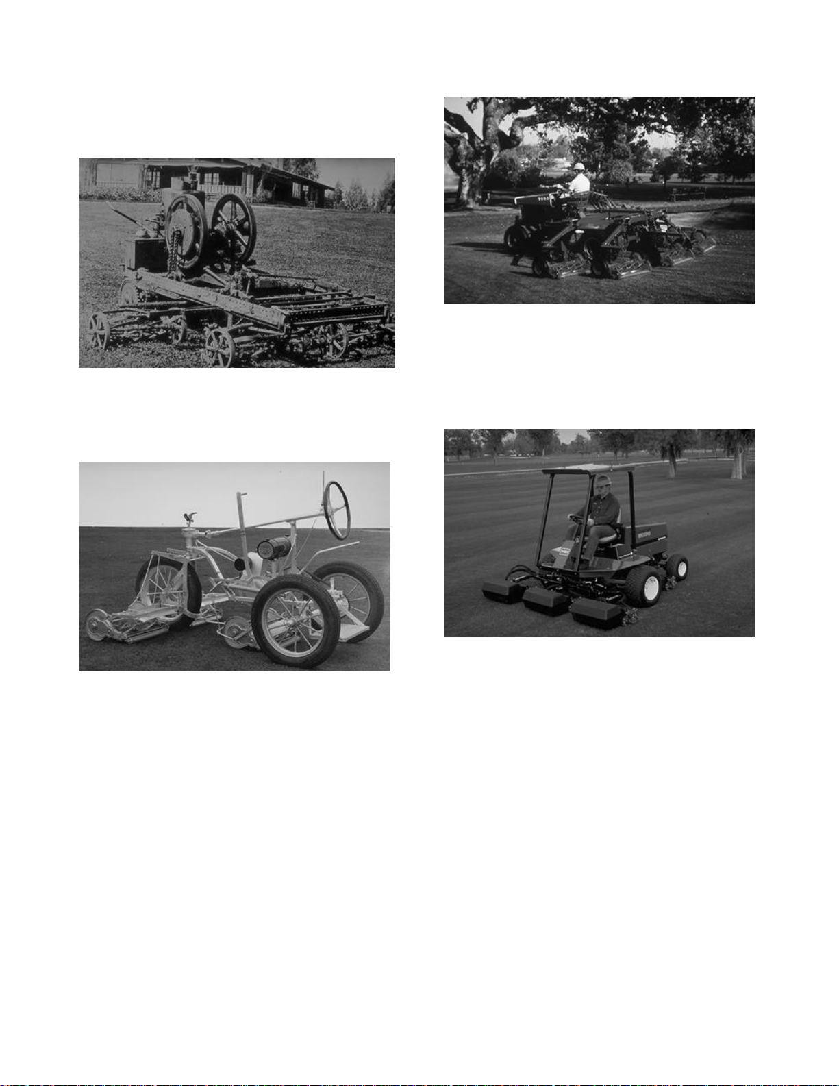
Introduction
Turf mowing equipment was very cumbersome and
inefficient when it was first developed back in the
early 1900’s.
Improvements were made through the years of Turf
equipment’s development, but it wasn’t until hydraulics became a part of the design that significant
improvements were made.
Use of hydraulics has increased to form a major
portion of turf product designs. Increases efficiency,
reliability, lowered maintenance costs, safer products and improved operator comfort are all byproducts of the increase in use of hydraulic systems on turf products.
An understanding of hydraulic systems and their
function on a product, is a necessity to properly
service, adjust, troubleshoot or test turf products.
Page 3

INDEX
1: HYDRAULIC PRINCIPLES, PAGE 2.
OBJECTIVE: To familiarize the technician with the basic fundamentals of hydraulic systems and their
operation.
2: HYDRAULIC SCHEMATICS, PAGE 7.
OBJECTIVE: Improve hydraulic technicians ability to read and comprehend hydraulic schematics, and
apply them to various repair jobs.
3: HYDROSTATIC TRANSMISSIONS, PAGE 14.
OBJECTIVE: Provide technicians with helpful information on the operation and maintenance of
hydrostatic transmissions.
4: HYDRAULIC HOSES AND FITTINGS, PAGE 19.
OBJECTIVE: Review proper hose and fitting service procedures.
5: TEST EQUIPMENT, PAGE 23.
OBJECTIVE: Instruct technicians on the proper test equipment and procedures to effectively and safely
diagnose hydraulic systems.
6: REVIEW QUESTIONS, PAGE 27.
Review Answers
1 - A. 6 - B. 11 - B. 16 - B.
2 - B. 7 - D. 12 - F. 17 - B.
3 - B. 8 - A 13 - A. 18 - D.
4 - A. 9 - C. 14 - A. 19 - D.
5 - B. 10 - B. 15 - C. 20 - B.
1
Page 4
Principles of Hydraulic Circuits and Components
Figure 1
Figure 5
Figure 3
Figure 4
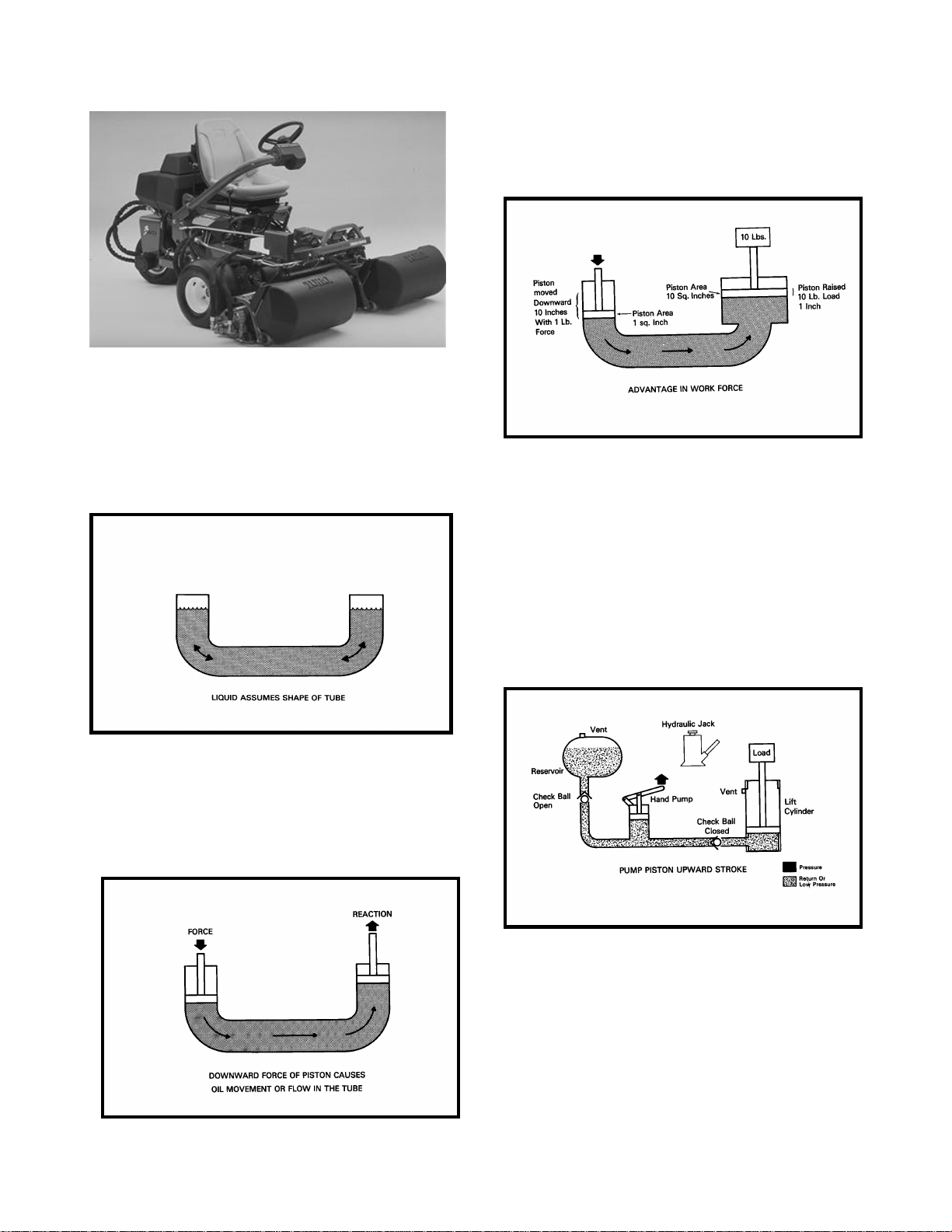
3. By making the containers or cylinders of different
sizes, the mechanical advantage in work force increases (Fig. 4)
Figure 1
A hydraulic circuit, whether it is simple or complex,
uses the following basic hydraulic principles:
1. A liquid can assume any shape and be bidirectional with out affecting its free flow movement
(Fig 2)
Basic Hydraulic Circuits and
Components Used in Turf Equipment.
2. Pascal’s law states that when a confined fluid is
placed under pressure, the pressure is transmitted
equally in all directions and on all faces of the container. This is the principle used to extend the ram
on a hydraulic cylinder (Fig 3)
Although hydraulic circuit layouts may vary significantly in different applications, many of the components are similar in design or function. The principle behind most hydraulic systems is similar to that
of the basic hydraulic jack. Oil from the reservoir is
drawn past a check ball into the piston type pump
during the pistons up-stroke (Fig 5)
2
Page 5
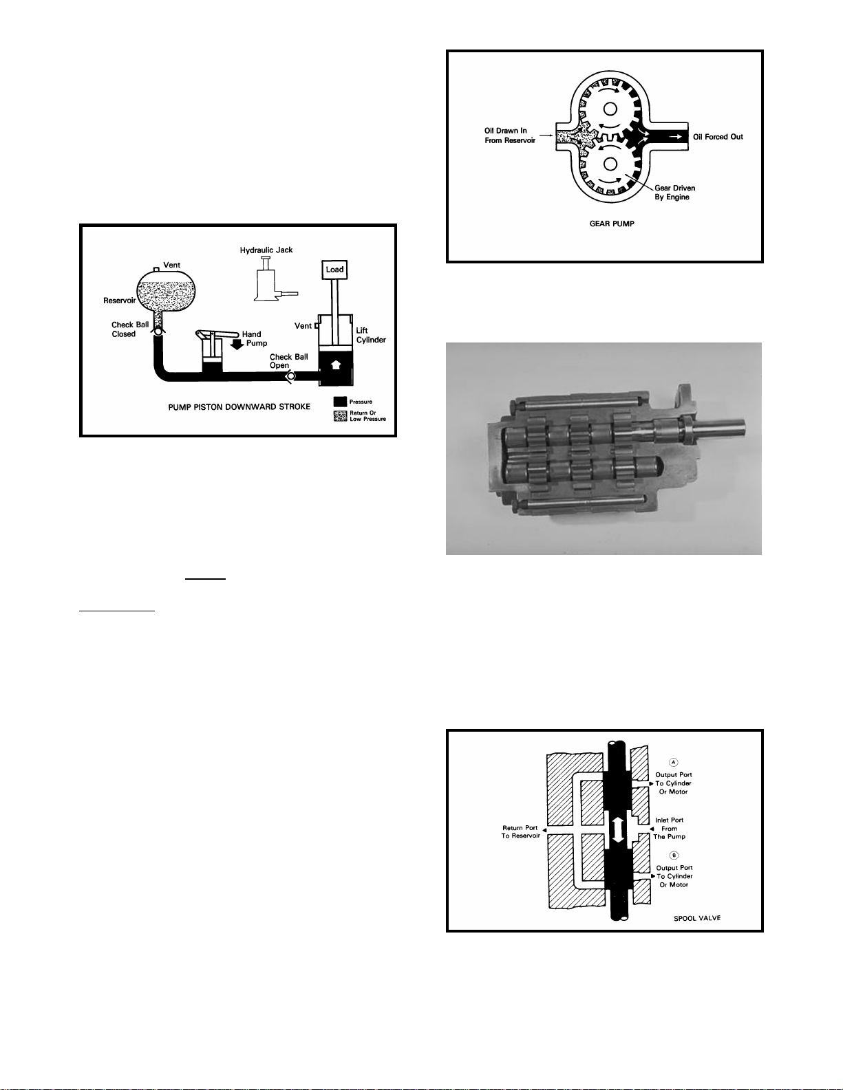
When the piston in the pump is pushed downward,
Figure 6
Figure 7
Figure 9
oil will be directed past a second check ball into the
cylinder. As the pump is actuated up and down, the
incoming oil will cause the cylinder ram to extend.
The lift cylinder will hold its extended position because the check ball is being seated by the pressure against it from the load side of the cylinder.
The cylinder will return to neutral by unseating or
bypassing the check balls, allowing the oil in the
cylinder to return back to the reservoir (Fig.6)
Below is a cutaway view of an actual three section
pump.
Because the pump displacement is usually much
smaller than the cylinder, each stroke of the pump
will move the cylinder a very small amount. If the
cylinder is required to move at a faster rate, the
surface area of the pump piston must be increased
and/or the rate which the pump is actuated must be
increased. OIL FLOW GIVES THE CYLINDER
RAM ITS SPEED OF MOVEMENT AND OIL
PRESSURE CREATES WORK FORCE.
We can improve the efficiency and Increase the
versatility of a basic circuit by adding some sophisticated components and changing the circuit layout. By incorporating a gear pump in place of a
hand piston pump, we increase oil flow to the cylinder which will increase the actuation rate of the
ram.
The most common type of pump is the gear pump
(Fig 7). As the gears in the pump rotate, suction is
created at the inlet port of the pump. The fluid is
drawn in to the pump and is carried in the spaces
between the gear teeth to the discharge port of the
pump. At the discharge side of the pump the gear
teeth mesh together and the oil is discharged from
the pump.
Figure 8
The flow from the pump to the cylinder is controlled
by a sliding spool valve which can be actuated by
an electric solenoid, or a hand or foot operated
lever. The valve shown in Figure 9 is a open center
valve, meaning that the oil flow is returned to the
reservoir when the valve is in the neutral position. If
the oil flow is stopped in the neutral position than
the valve is a closed center valve.
3
Page 6
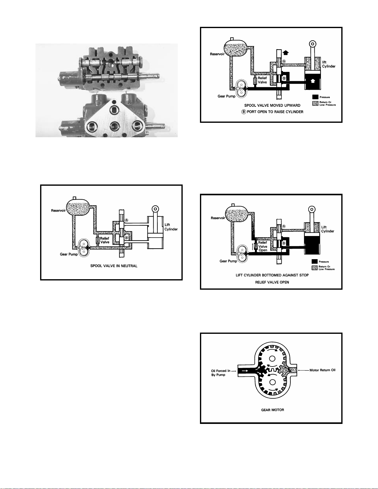
Below is a cutaway of an actual hydraulic control
Figure 12
Figure 11
Figure 13
Figure 14
valve (Fig 10).
Figure 10
Here we see have a spool valve in our simple hydraulic
system, we can see that the valve is in the neutral position and all the flow from the pump is directed back to
the reservoir.
If the spool is moved upward, the oil flow from the
pump is directed through the spool to one end of
the lift cylinder. The oil in the opposite end of the
cylinder is pushed out as the ram extends, and will
pass through the spool and return to the reservoir.(Fig 12).
Since the fluid from a positive displacement pump
must flow continuously whenever the pump is running it must have some where to go if not being
used by the actuators. If the load on the cylinder
becomes too great or if the ram bottoms out, the
flow from the pump will be directed past the relief
valve returning to the reservoir (Fig 13).
Substituting the lift cylinder with a gear motor, we
can now utilize out basic circuit to create rotational
movement to drive attachments (Fig 14).
4
Page 7
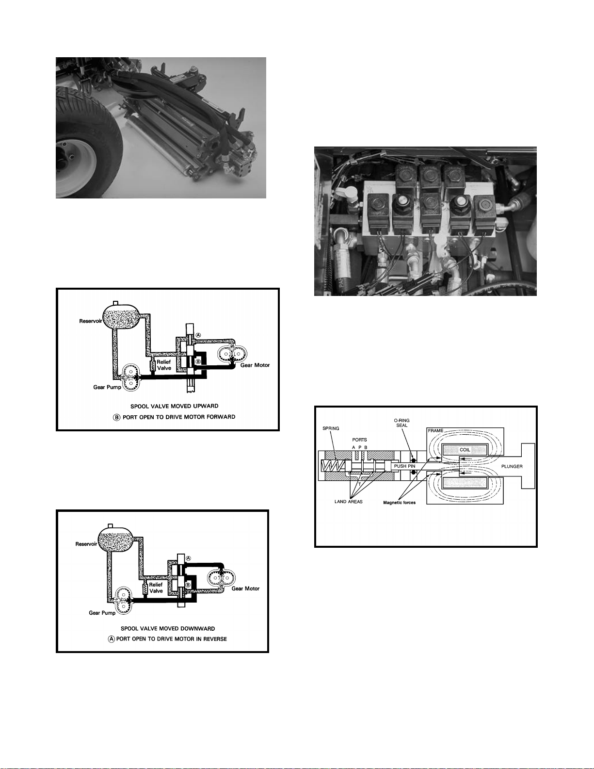
Figure 15 shows a hydraulic reel motor.
Figure 16
Figure 17
Figure 19
Figure 15
Figure 16 illustrates the basic circuit and components necessary to drive the reel cutting units. With
the spool in the upward position, the oil flow is directed through the spool valve to the lower port
driving the motor in the forward direction.
solenoid valves and the internal porting to make
the valve operate (Fig 18). The outer ports on the
valve body are threaded to allow hoses and lines to
be connected to the valve body. Care should be
taken when tightening the hose and line fittings so
the valve is not distorted by over tightening of the
connections. Tighten the line and hose connections
to the correct Flats From Finger Tight (F.F.F.T.)
spec. listed in the service manual.
Figure 18
Actuating the spool to the down position, the flow of
oil from the pump is directed to the opposite port of
the motor. The motor than rotates in the reverse direction (Fig 17).
The electric solenoid valve operates by supplying
electrical current to a coil magnet, the magnetic
field moves a valve spool and this directs the oil.
The thing to remember is that the only difference
between a hydraulic\electric valve, and a regular
hydraulic valve is the way that the spool is moved.
The solenoid valves consist of the valve cartridge
and the solenoid coil (Fig 19). To disassemble the
valve remove the coil assembly and then carefully
unscrew the valve body. The O-rings and seals
should be replaced whenever a valve body is removed or replaced.
Another type of valve system becoming popular in
turf equipment is the electric solenoid type valve
system. The solenoid valve system consists of a
machined valve body. This valve body contains the
5
Page 8
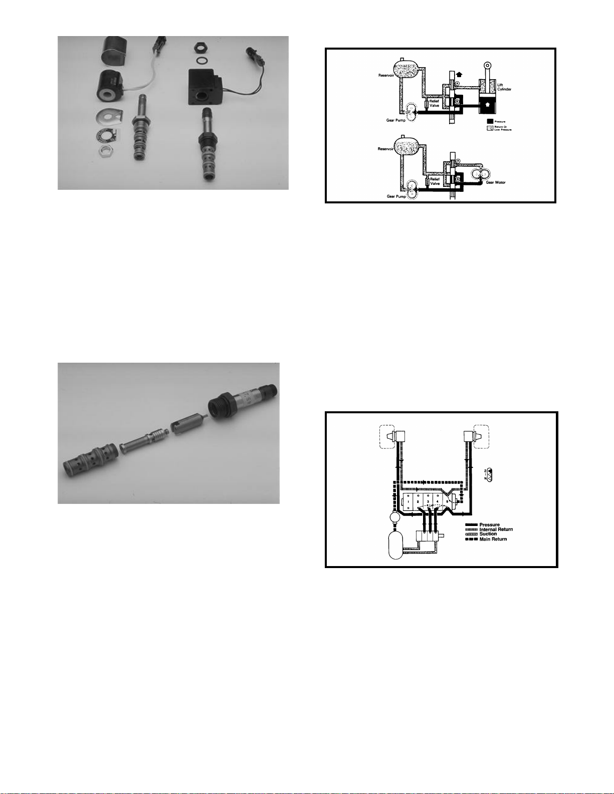
Figure 20
Figure 22
Figure 23
Inside the cartridge valve there is the valve spool,
the armature and the armature spring. The manufacturing tolerances are extremely close and great
care should be used when cleaning this type of
valve. Cartridge valves used in most Toro equipment should not be disassembled. Figure 20 is for
illustrative purposes only. The best way to clean the
cartridge valve is to submerge the valve in clean
mineral sprits and use a probe to push the internal
spool in and out 20 to 30 times to flush out the
contamination. Mineral sprits does not affect the Oring material.
Figure 23 shows the actual hydraulic circuit for a
Greensmaster 3000. This circuit and components
are used to drive the unit in the No.1 traction position. When the engine is started, the pump draws
oil from the reservoir through the suction lines. Oil
from the No.4 section of the pump passes through
the fitting in the No.4 spool valve into the valve.
The traction lever, when located in the No.1 position, moves the spool so oil is directed to flow into
the No.5 metering valve section. When the traction
pedal is pushed forward oil flows out the lines at the
rear of the metering valve section to each motor to
drive the motors. Low pressure oil returns through
the valve and the main return line, through the filter
to the reservoir.
Figure 21
Understanding the basic hydraulic systems and
components can be of great value when troubleshooting and testing hydraulic equipment. Most hydraulic systems will be similar to one of these two
basic systems (Fig 22).
The more sophisticated a hydraulic system becomes, the greater the importance of separating
the system into individual circuits when diagnosing
a hydraulic problem.
6
Page 9
Introduction To Hydraulic Schematics
A
B
Accurate diagrams of hydraulic circuits are essential to the technician who must repair it. The diagram shows how the components will interact. It
shows the technician how it works, what each component should be doing and where the oil should be
going, so that he can diagnose and repair the system.
CIRCUIT DIAGRAMS
There are two types of circuit diagrams.
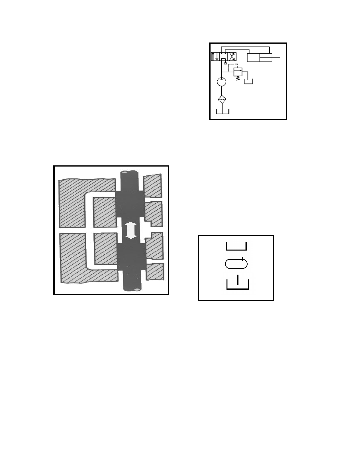
A: Cutaway Circuit Diagrams show the internal
construction of the components as well as the oil
flow paths. By using colors, shades or various patterns in the lines and passages, they are able to
show many different conditions of pressure and
flow (Fig 1).
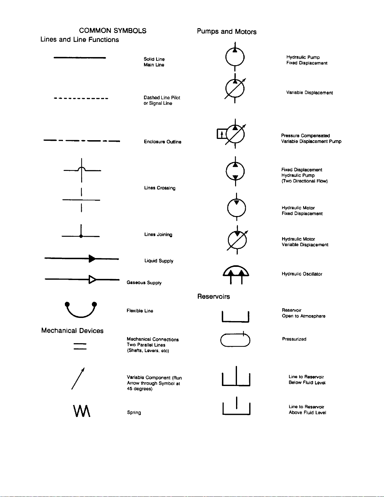
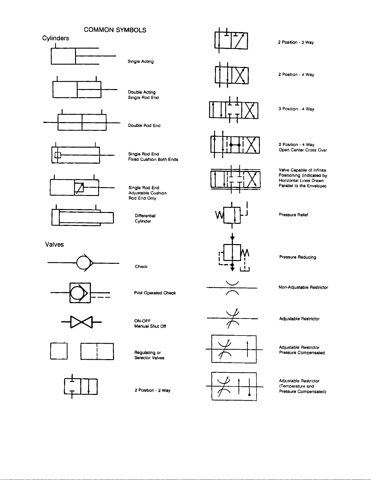
1. Schematic symbol systems
A: I.S.O = International Standards Organization.
B: A.N.S.I. = American National Standards Institute
C: A.S.A = American Standards Association
D: J.I.C. = Joint Industry Conference
A combination of these symbols are shown in this
manual. There are difference between the systems
but there is enough similarity so that if you understand the symbols in this manual you will be able to
interpret other symbols as well.
Figure 2
Figure 1
B: Schematic Circuit Diagrams are usually
preferred for troubleshooting because of their ability
to show current and potential system functions. A
schematic diagram is made up of consistent
geometric symbols for the components and their
controls and connections (Fig 2).
2. Hydraulic reservoirs
C
Figure 3
Reservoirs (Fig 3) are pictured as either an open
square meaning it is a vented reservoir, or a closed
reservoir meaning that it is a pressurized reservoir.
Every system reservoir has at least two lines connected to it, and some have many more. Often the
components that are connected to it are spread all
over the schematic. Rather than having a lot of
confusing lines all over the schematic, it is customary to draw individual reservoir symbols close to
the component. Similar to the ground symbol in
some wiring schematics. The reservoir is usually
the only component to be pictured more than once.
7
Page 10
3. Lines
5. Hydraulic motors
LINES
Figure 4
A hydraulic line, tube, hose or any conductor that
carries the liquid between components is shown as
a line. Some lines have arrows to show direction of
oil flow, and lines may be shown as dashed lines to
show certain types of oil flow.
Figure 5
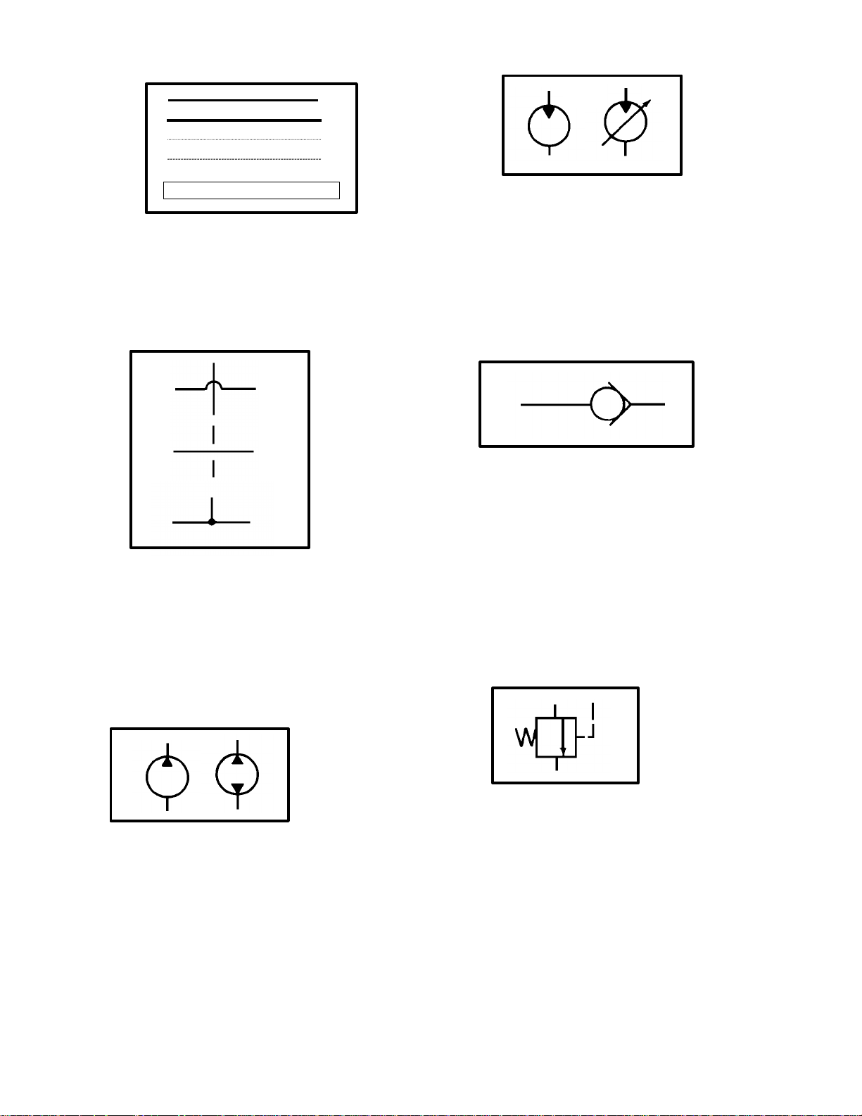
There are lines that cross other lines (Fig 5) but are
not connected, there are several ways to show lines
that are not connected. Lines that are connected
are shown with a dot or sometime just as two lines
crossing. If the schematic shows a specific symbol
to show lines that are not connected then anything
else is connected.
Figure 7
Hydraulic motor symbols (Fig 7) are circles with triangles, but opposite of a hydraulic pump, the triangle points inward to show the oil flows in to the
motor. One triangle is used for a non-reversible
motor and two triangles are used for a reversible
motor. An arrow through a motor shows that it is a
variable speed motor.
6. Check valves
Figure 8
A check valve (Fig 8) is shown as a ball in a V
seat. When oil pressure is applied to the left side of
the ball, the ball is forced into the V and no oil can
flow. When oil pressure is applied to the right side
of the ball, the ball moves away from the seat and
oil can flow past it. A by-pass check is a one way
valve with a spring on the ball end of the symbol.
This shows that pressurized oil must overcome the
spring pressure before the ball will unseat.
7. Relief valves
4. Hydraulic pumps
Figure 6
There are many basic pump designs. (Fig 6) A simple fixed displacement pump is shown as a circle
with a triangle that is pointing outward. The triangle
points in the direction that the oil will flow. If the
pump is reversible or is designed to pump in either
direction, it will have two triangles in it and they will
point opposite of each other indicating that oil may
flow in both directions.
Figure 9
A relief valve (Fig 9) is shown as a normally closed
valve with one port connected to the pressure line
and the other line connected to the reservoir. The
flow direction arrow points away from the pressure
line and toward the reservoir. When pressure in the
system overcomes the valve spring, pressure is directed through the valve to the reservoir.
8
Page 11
8. Hydraulic valves
B
10. Hydraulic Cylinders
Figure 10
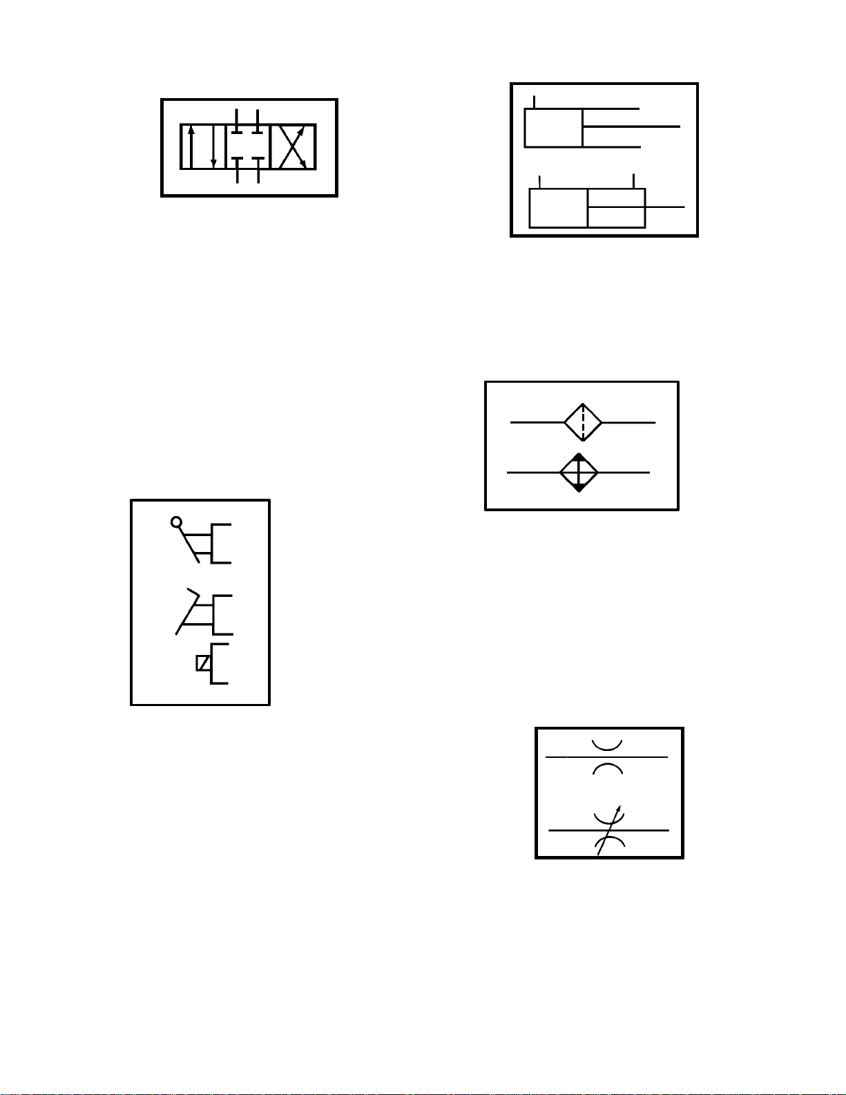
A control valve (Fig 10) has envelopes (squares)
that represent the valve spool positions. There is a
separate envelope for each valve position and
within these envelopes there are arrows showing
the flow paths then the valve is shifted to that position. All the port connections are drawn to the envelope that shows the neutral position of the valve.
We can mentally visualize the function of the valve
in any position. A valve that has parallel lines
drawn outside of the valve envelopes shows that
this valve is capable of infinite positioning. This
valve usually operated between the positions
shown. An example of this type of valve would be a
flow priority valve or a pressure regulating valve.
9. Actuators
A
C
Figure 12
A cylinder symbol (Fig 12) is a simple rectangle
representing the barrel. The rod and piston are represented by a tee that is inserted into the rectangle.
The symbol can be drawn in any position.
11. Miscellaneous
Figure 13
Filters, strainers and heat exchangers (coolers) are
shown as squares that are turned 45 degrees and
have port connections at the corners. A dotted line
90 degrees to the oil flow indicates a filter or a
strainer. A solid line 90 degrees to the oil flow with
2 triangles pointing out indicates a cooler. The
symbol for a heater is like that of a cooler, except
the triangles point inward.
12. Flow controls
Figure 11
The valve spools can be controlled a variety of
ways. The top picture (A) shows the symbol for a
lever control. The middle picture (B) shows the
symbol for a pedal control (foot operated). The
lower control (C) is an electric solenoid.
Figure 14
The basic flow control (Fig 14) is a representation
of a restrictor. If the restrictor is adjustable a
slanted arrow will be drawn across the symbol.
9
Page 12
13. Valve Enclosures
Figure 15
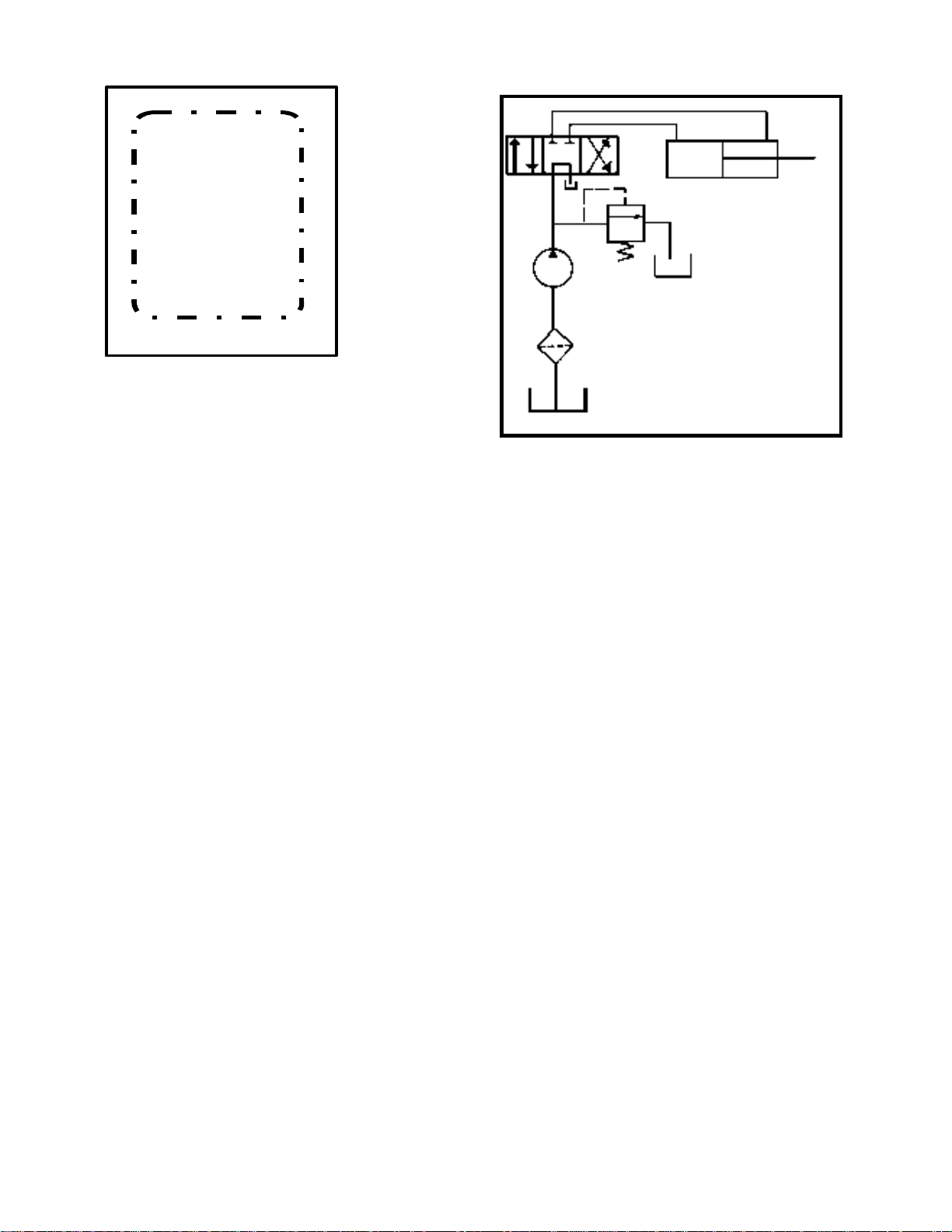
When you see an enclosure outline, (Fig 15) that
indicates that there are several symbols that make
up a component assembly such as a valve body or
valve stack. The enclosure outline appears like a
box and is broken with dashes on all sides.
14. Complete hydraulic schematic
Figure 16
Here we have a simple hydraulic schematic (Fig
16) using the symbols that we discussed and how
they are used in a complete schematic. You can
see that we have a hydraulic pump which gets it’s
fluid from the reservoir, pulls the fluid through the
filter than sends it to the valve. The valve directs
the oil to the hydraulic cylinder.
NOTES
__________________________________________
__________________________________________
__________________________________________
__________________________________________
__________________________________________
__________________________________________
__________________________________________
__________________________________________
__________________________________________
__________________________________________
__________________________________________
__________________________________________
10
Page 13
111213
Page 14
Page 15
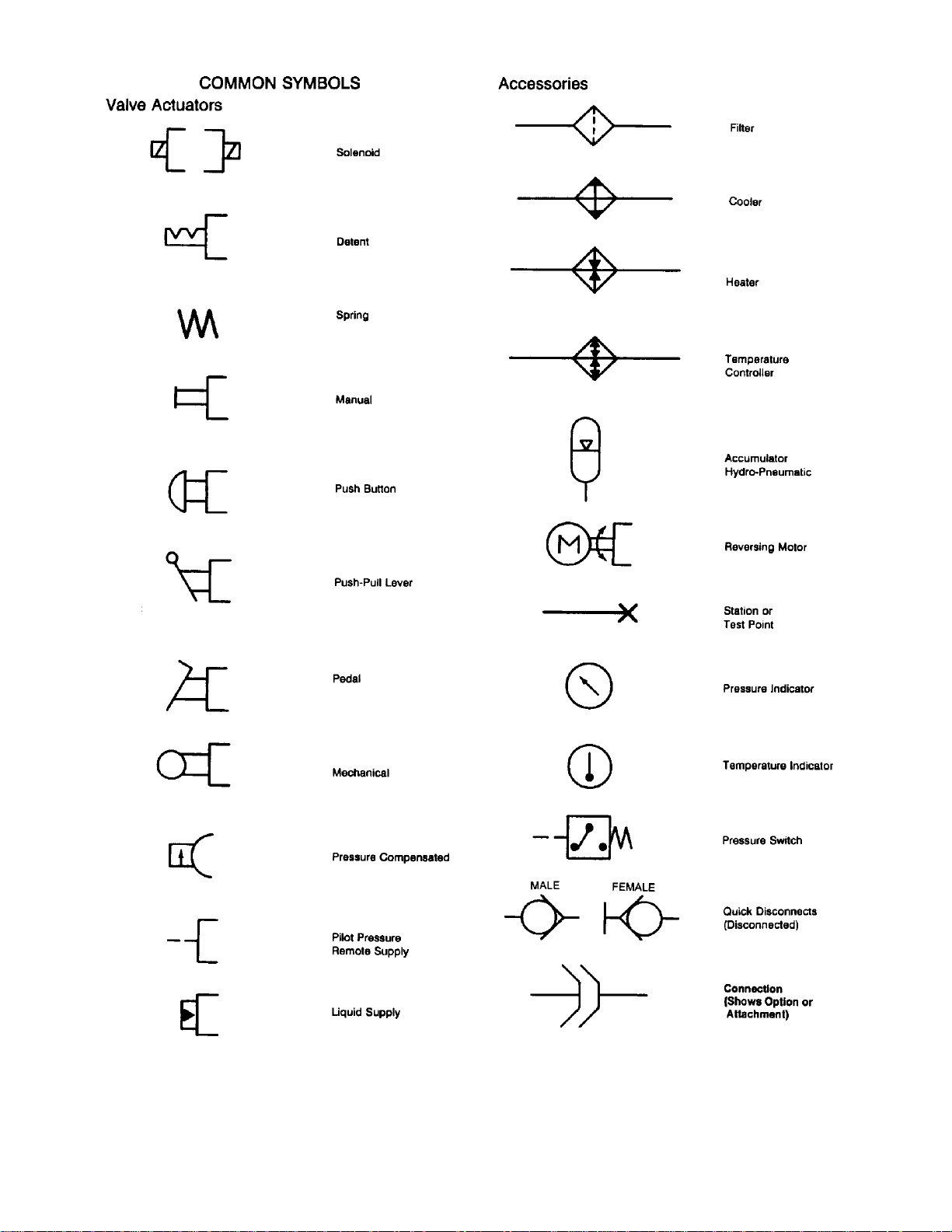
Page 16
Hydrostatic Transmissions
Hydrostatic transmissions have become quite
popular in Turf equipment applications. Their increased use has been due to their simplicity, low
maintenance requirements, compact design, operator convenience, and resistance to operator abuse.
Hydrostatic transmissions can be easily repaired
and maintained if you have a basic understanding
of the components and their function.
To begin to understand hydrostatic drive units, lets
start by looking at the various types and configurations of hydrostatic transmissions.
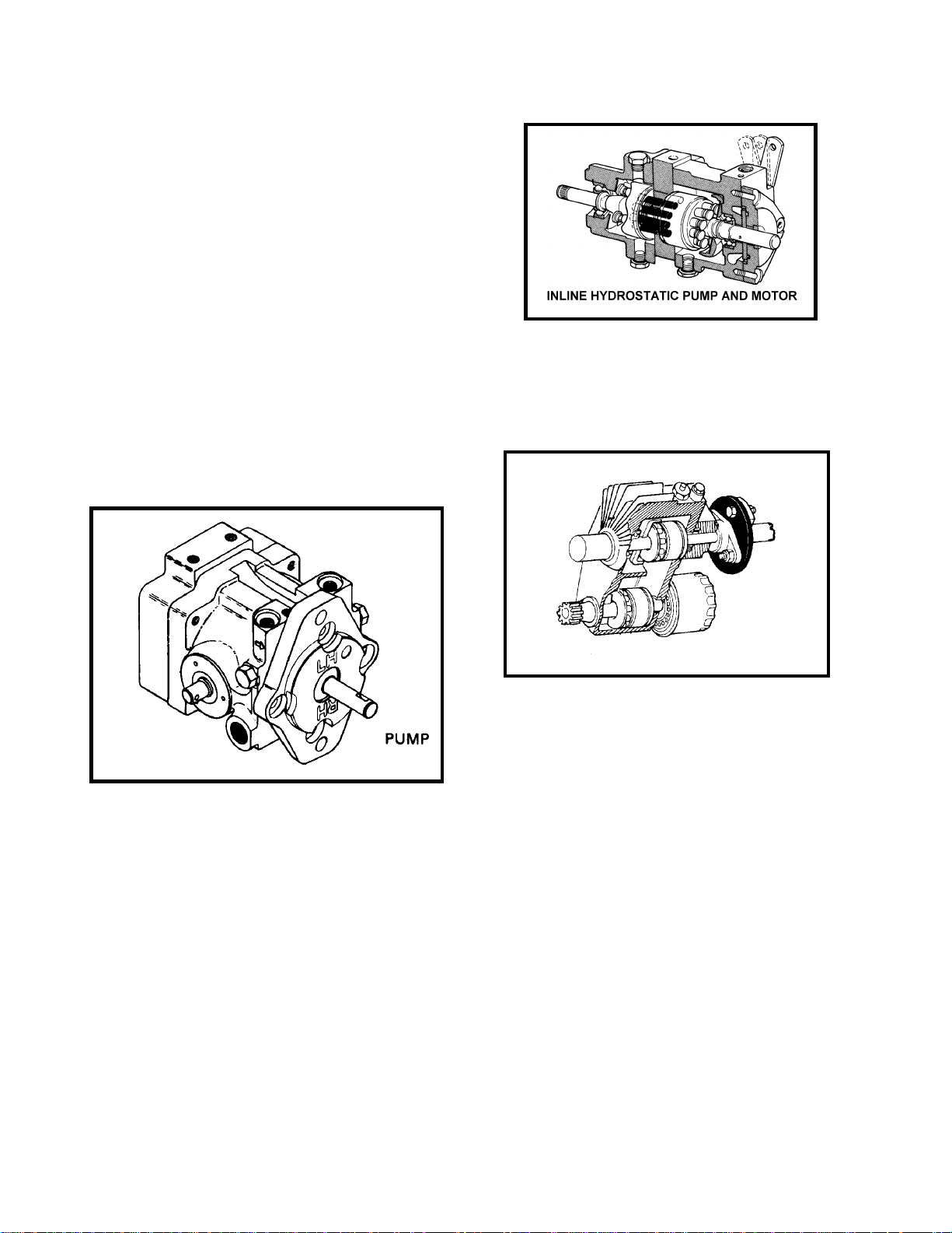
Figure 2
The first type is a hydrostatic system which consists
of a hydrostatic pump with a remotely mounted motor. (Fig 1) In this type of hydrostatic system the
hydrostatic pump is mounted by, and driven by, the
units engine. The pump is connected to the drive
motor by hoses or steel lines. These motors can be
mounted directly to the wheels or to a drive axle.
Figure 1
A different type of hydrostatic drive system is an
inline pump and motor system. (Fig 2) In this system the motor and pump are constructed as a single unit, this eliminates the necessity of high pressure drive lines between the pump and the motor.
This unit is normally mounted to a drive axle or
transaxle.
A similar version is the U-type transmission (Fig 3).
In this type of system the pump and motor are constructed as a common component with the pump
usually located above the motor.
Figure 3
All three systems work well in their designed applications. The remote motor design works well when
there is no transmission or transaxle, or when the
location of the engine and the drive system call for
such a configuration. The U type hydrostatic system is more compact while the inline hydrostatic
system is usually easier to repair and maintain.
We will be using the inline hydrostatic pump and
motor system in this session for illustration purposes.
A hydrostatic drive consists of a hydrostatic pump,
which pumps oil to a drive motor. The most significant feature of a hydrostatic system is the pump.
The pump is a variable displacement pump. This
means that the output of the pump can be varied
and is not controlled only by the engine RPMs like
a fixed displacement pump. This requires that the
pump needs to be a piston pump.
14
Page 17
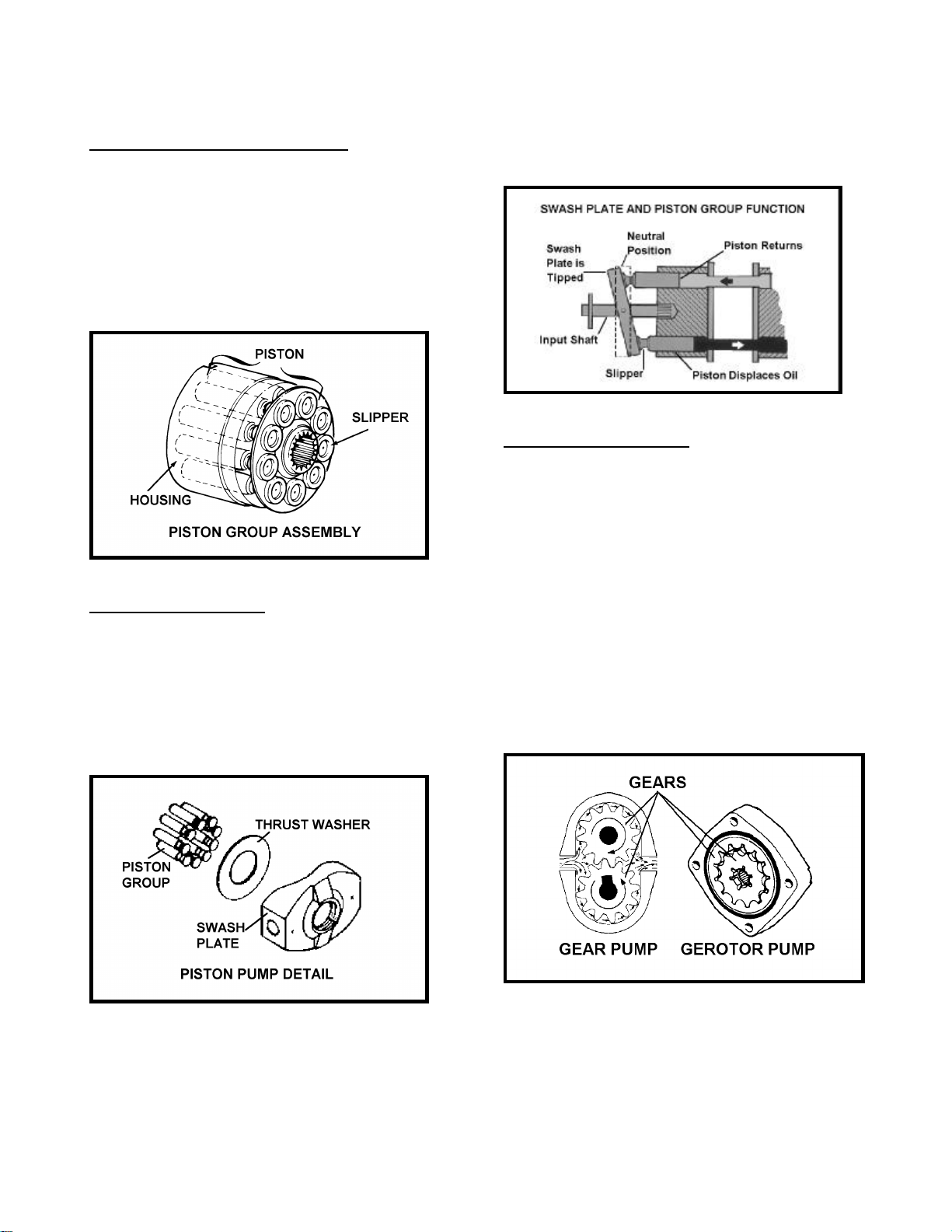
The pump consists of the following components.
The piston group assembly. (Fig 4)
This rotating piston group is mounted to the input
shaft and is driven by the engine. It consists of a
piston block with numerous precision machined
bores which house the pump pistons. The small
pump pistons consist of the piston and the piston
slipper. The slipper is usually a brass or aluminum
component which is connected to the piston and
moves the pistons when the pump is operating.
Figure 4
The swash plate. (Fig 5)
The piston slippers pivot and slide against a hardened washer called a thrust washer. The thrust
washer is located in the swash plate. The swash
plate pivots on two support pins and controls the
pump output. As the operator moved the traction
control pedal to increase travel speed the swash
plate angle increases.
pumped. As the operator moves the traction control
pedal the angle of the swash plate increases, this in
turn increases the piston travel. As the piston travel
increases the amount of oil pumped increases and
the travel speed changes.
Figure 6
The charge pump. (Fig 7)
While the transmission is in operation there is a
constant loss of oil (by design) within the components of the pump and motor. For example, holes
in the end of each piston allow a small amount of
oil to form a cushion between the slipper’s face and
the thrust washer. This oil must be continuously replenished. Built in to the system is pump called a
charge pump. This pump can be a gear pump, or a
gerotor pump. Both of these pumps are fixed displacement. Fixed displacement means that the
pump’s output is fixed by the RPM of the engine. It
cannot be varied except by increasing or decreasing the speed of the engine. Excessive oil not required by the drive circuit opens the charge relief
valve and flows back to the reservoir.
Figure 5
As the piston group spins the pistons are moved in
and out of their bores and they pump oil. The
quantity of the oil being pumped is controlled by the
angle of the swash plate. As long as the swash
plate is kept in the neutral position, no oil will be
Figure 7
15
Page 18
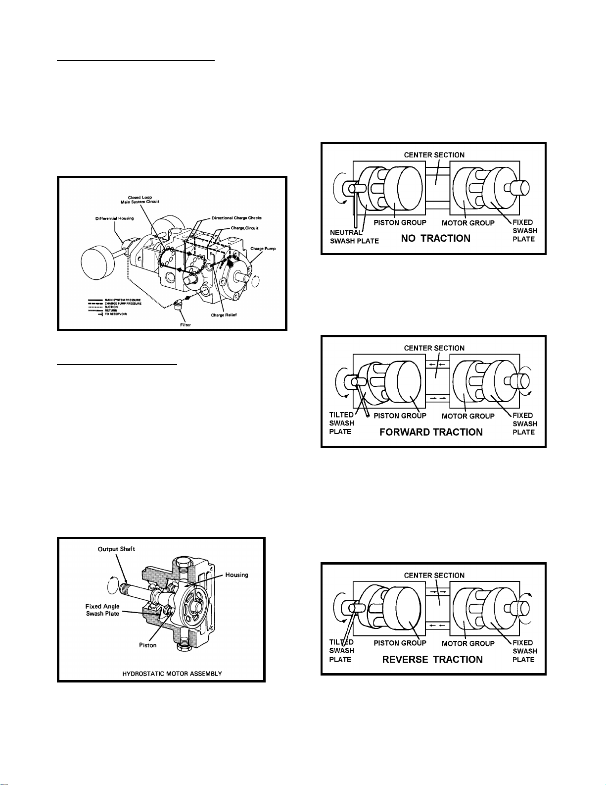
Directional charge checks. (Fig 8)
OVERALL OPERATION
Directional charge check valves are incorporated
into the charge circuit to direct the charge pump
output to the low pressure side of the drive circuit.
The oil will flow into the low pressure side to replace the oil lost through normal leakage. The oil in
the high pressure side closes the remaining charge
check valve so that no high pressure oil can bleed
off into the charge circuit.
Figure 8
Hydrostatic motor. (Fig 9)
As the engine turns the pump rotating group, the
pistons run on the swash plate which is in the neutral position. (Fig 10) With the swash plate in neutral there is no movement of the pistons so no oil is
being pumped.
Figure 10
As the operator moves the traction control pedal
the swash plate angle increases and the pump pistons begin to displace oil. This oil is directed to the
pump section and the unit moves. (Fig 11)
On a remote hydrostatic motor type system the hydrostatic motors can be a simple gear type motor or
a piston type motor. When the motor is built as part
of the complete assembly like an inline or U type
system the motor is a piston type motor very similar the piston pump except that the swash plate is
usually a fixed swash plate. Being fixed the stroke
of the pistons remain constant. The motor’s speed
of rotation can not be changed except by changing
the volume of oil that it receives from the pump.
Remember that a given column of oil will cause the
motor to turn at a given speed. More oil will increase the motor speed. Less oil will slow it down.
Figure 11
When the operator needs to change directions the
traction pedal is moved back to the neutral position
and than moved to the reverse position. In the reverse position the swash plate moves in the opposite direction as it did in the forward direction. In
this position the oil is pumped to the opposite side
of the motor and the unit moves in reverse. (Fig 12)
Figure 9
Figure 12
16
Page 19
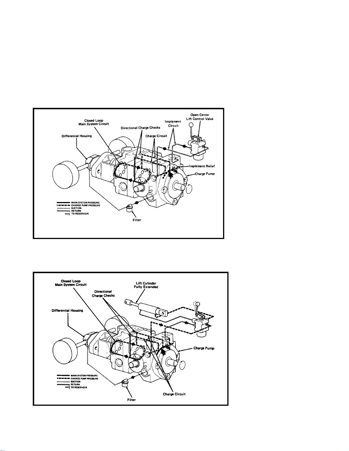
IMPLEMENT CIRCUIT (Fig 13)
Some machines require hydraulic oil to operate the
implement lift functions. This can be accomplished
by using a larger charge pump. This pump has a
larger displacement of oil than is needed to replenish the oil lost in the drive circuit. The excess oil not
required to replenish the drive circuit, opens and
passes through the charge relief and is directed to
the implement lift valve. At the implement valve the
oil can be directed to a lift cylinder.
NOTE: It is important to realize that the main circuit
must have enough oil flow and pressure supplied to
it to replenish the oil lost in the drive circuit. Should
the main circuit develop excessive leakage, the
charge relief valve will not be opened and no oil will
flow to the implement circuit.
Figure 13
If the lift control lever remains actuated after the lift cylinder is extended, (Fig 14) the flow from the charge
pump is forced through the implement relief valve and will return to the reservoir.
Figure 14
17
Page 20

The hydrostatic transmission will provide trouble
free operation if it is serviced and maintained properly. There are, however, a few simple items that
are often overlooked when poor performance is
evident.
even though the traction control pedal or hand
lever is fully pushed.
3. The tow or bypass valve is partially open, letting
oil bypass in the main system.
1. The “ no-load” engine RPM. setting is too slow.
2. Worn, loose or misadjusted linkage is not positioning the swash plate actuating arm far enough,
4. The hydraulic oil filter or inlet line is not tightened sufficiently; air is being drawn in past the filter
seal into the charge pump, and then into the main
circuit. Air in the hydraulic system will cause cavation and damage the rotating components.
NOTES
_________________________________________________
_________________________________________________
_________________________________________________
_________________________________________________
_________________________________________________
_________________________________________________
_________________________________________________
_________________________________________________
_________________________________________________
_________________________________________________
_________________________________________________
_________________________________________________
_________________________________________________
_________________________________________________
_________________________________________________
_________________________________________________
_________________________________________________
_________________________________________________
_________________________________________________
_________________________________________________
18
Page 21

Hydraulic Hoses and Fittings
Hydraulic Hoses
Hydraulic hoses are subject to extreme conditions
such as, pressure differentials during operation and
exposure to weather, sun, chemicals, high temperature operating conditions or mishandling during
operation or storage. Hoses that move during operation are more susceptible to these conditions
than others.
Before disconnecting or performing any
work on a hydraulic system, all pressure
in the system must be relieved by
stopping the engine and lowering or
supporting the implement.
Inspect hoses frequently for signs of deterioration
or damage. Check hoses for leakage and replace
when leaks are found.
Figure 1
When replacing a hydraulic hose, be sure that the
hose is straight (not twisted) before tightening the
fittings. This can be done by observing the imprint
on the hose. Using two wrenches, hold the hose
straight with one wrench and use the other wrench
to tighten the hose swivel nut to the fitting. Use
procedures shown in the Toro Hydraulic Hose
Servicing Manual, Form No. 94-813-SL.
Keep body and hands away from
pin hole leaks or nozzles that eject
hydraulic fluid under pressure. Use
paper or cardboard, not hands, to
search for leaks. Hydraulic fluid
escaping under pressure can have
sufficient force to penetrate the
skin and do serious damage. If
fluid is injected into the skin, it
must be surgically removed within
a few hours by a doctor familiar
with this type of injury or gangrene
may result.
Figure 2
19
Page 22
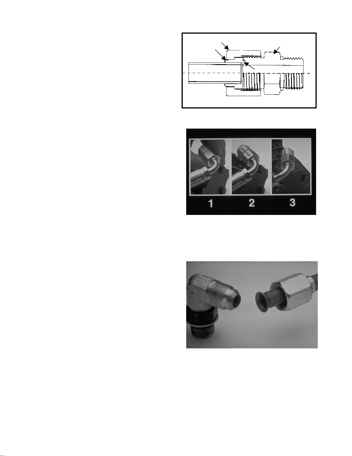
O-ring Face Seal (ORFS)Fittings
1. Make sure both threads and sealing surfaces are
free of burrs, nicks, scratches, or any foreign material.
2. Make sure the O-ring is installed and properly
seated in the groove. It is recommended that the
O-ring be replaced any time the connection is
opened.
3. Lubricate the O-ring with a light coating of oil.
4. Put the tube and fitting squarely into position on
the face seal end of the fitting and tighten the nut
until finger tight.
5. Mark the nut and fitting body. Hold the body with
a wrench. Use another wrench to tighten the nut to
the correct flats from finger tight (F.F.F.T.). The
markings on the fittings will verify that the connection has been tightened
Size F.F.F.T
4 (1/4 in. Nominal hose or tubing) .75 ± .25
6 (3/8 in.) .75 ± .25
8 (1/2 in.) .75 ± .25
10 (5/8 in.) 1.00 ± .25
16 (1 in.) .75 ± .25
JIC 37º Flare Fittings
1. Make sure both threads and sealing surfaces are
free of burrs, nicks, scratches, or any foreign material. Check for a cracked or distorted flare
(sealing point).
Nut
Sleeve
Body
Seal
Figure 3
Figure 4
Line tightening procedure:
1. Tighten connection finger tight.
2. Mark connector.
3. Tighten correct number of flats from spec. Chart.
2. Tighten the nut finger tight until it bottoms out
against the seat. Mark a line on the nut and the fitting body.
3. Hold the body with a wrench. Use another
wrench to tighten the nut to the correct flats from
finger tight (F.F.F.T.). The markings on the nut and
fitting body will verify that the connection has been
tightened. After tightening, extend the line from the
nut to the body (optional for ease of remake).
Size Initial F.F.F.T. Remake F.F.F.T
4 (1/4 in. Nominal) 2 - 2½ ¾ - 1
6 (3/8 in.) 2 - 2¼ 1
8 (1/2 in.) 1½ - 1¾ 1
10 (5/8 in.) 1½ - 1¾ ¾
12 (3/4 in) 1½ ¾
14 (5/8 in) 2 1¼
16 (1 in.) 1¼ - 1½ ¾ - 1
Figure 5
20
Page 23
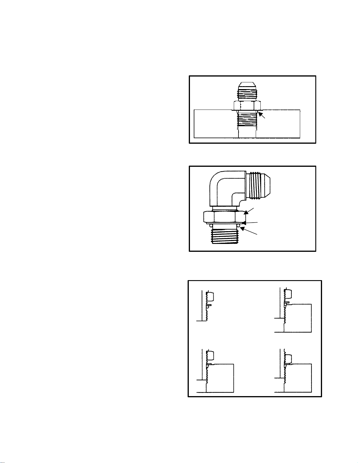
SAE Straight thread O-ring Port Fittings
(Non-Adjustable)
1. Make sure both threads and sealing surfaces are
free of burrs, nicks, scratches, or any foreign material.
2. Always replace the O-ring seal when this type of
fitting shows signs of leakage.
3. Lubricate the O-ring with a light coating of oil.
4. Install the fitting into the port and tighten it down
until finger tight.
5. Tighten the fitting to the correct flats from finger
tight (F.F.F.T.).
Size F.F.F.T.
4 (1/4 in. nominal hose or tubing) 1.00 ± .25
6 (3/8 in.) 1.50 ± .25
8 (1/2 in.) 1.50 ± .25
10 (5/8 in.) 1.50 ± .25
12 (3/4 in.) 1.50 ± .25
16 (1 in.) 1.50 ± .25
Size F.F.F.T.
4 (1/4 in. nominal hose or tubing) 1.00 ± .25
6 (3/8 in.) 1.50 ± .25
8 (1/2 in.) 1.50 ± .25
10 (5/8 in.) 1.50 ± .25
12 (3/4 in.) 1.50 ± .25
16 (1 in.) 1.50 ± .25
O-Ring
Figure 6
SAE Straight thread O-ring Port Fittings
(Adjustable)
1. Make sure both threads and sealing surfaces are
free of burrs, nicks, scratches, or nay foreign material.
2. Always replace the O-ring seal when this type of
fitting shows signs of leakage.
3. Lubricate the O-ring with a light coating of oil.
4. Turn back the jam nut as far as possible. Make
sure the back up washer is not loose and is pushed
up as far as possible (step 1).
5. Install the fitting into the port and tighten finger
tight until the washer contacts the face of the port
(step 2).
6. To put the fitting in the desired position, unscrew
it by the required amount, but no more than one full
turn (step 3).
7. Hold the fitting in the desired position with a
wrench and turn the jam nut with another wrench
to the correct flats from finger tight (F.F.F.T.)
(step 4)
Step 1
Step 2
Lock nut
Back-up Washer
O-Ring
Figure 7
Step 3
Step 4
21
Figure 8
Page 24
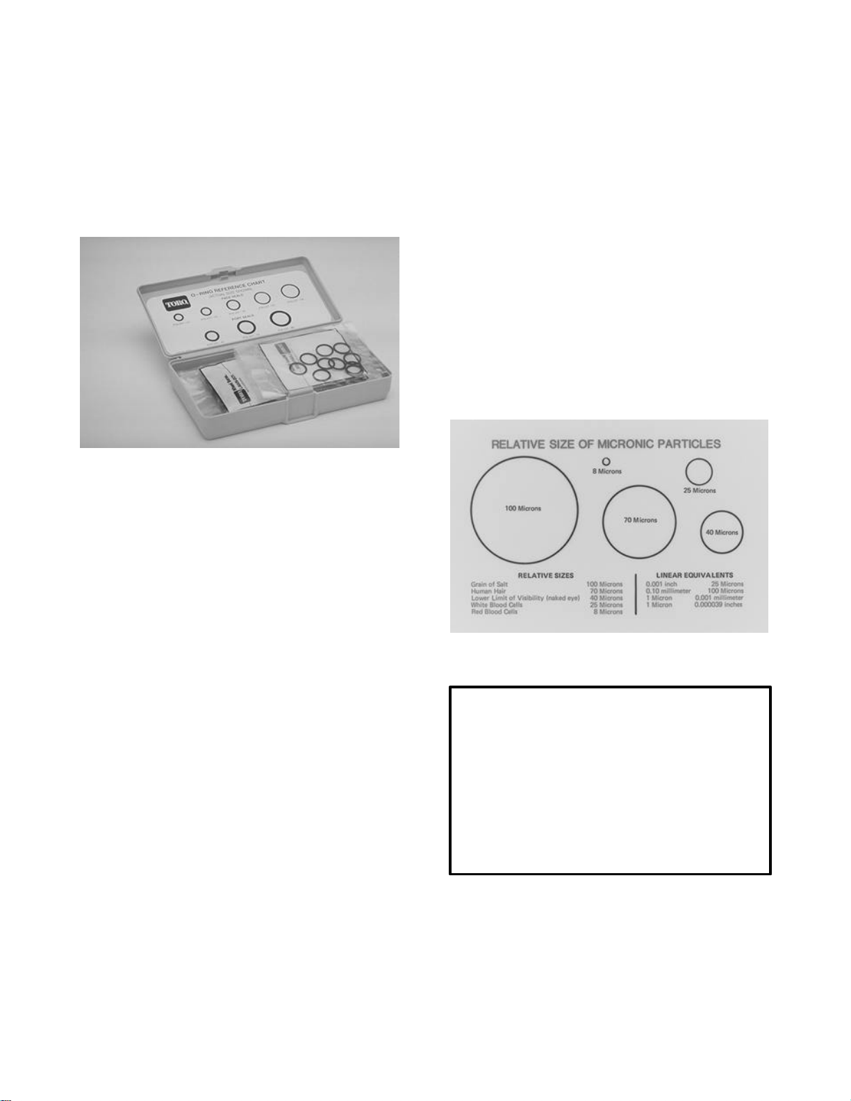
O-ring Kit
After Repair or Replacement of Components
O-ring face seal connections on Toro equipment
require the use of special 90 Durometer O-rings.
Toro recommends that the O-rings need to be replaced whenever a connection is loosened. An Oring kit is available containing quantities of O-rings
for both face seal and port seal connections used in
Toro equipment.
O-ring Kit: P/N 16-3799
Figure 9
Removing Hydraulic System Components
1. Check oil level in hydraulic reservoir and add
correct oil if necessary.
IMPORTANT: Drain and refill hydraulic system
reservoir and change oil filter if component failure
was severe or system is contaminated. If there is a
severe failure in a closed loop system, flush all
lines and components in the system.
2. After repairs, check the control linkage for proper
adjustment, binding or broken parts.
3. After disconnecting or replacing components,
operate the machine functions slowly until the air is
out of the system.
4. Check for hydraulic leaks. Shut off the engine
and correct leaks if necessary. Check oil level in
the reservoir and add the correct oil if necessary.
1. Thoroughly clean the machine before disconnecting, removing or disassembling any hydraulic
components. Always keep in mind the need for
cleanliness when working on hydraulic equipment.
2. Put caps or plugs on any hydraulic lines or fitting
left open or exposed.
3. Put labels on disconnected hydraulic lines and
hoses for proper installation after repairs are completed.
The most important rule of hydraulic
system maintenance is...
KEEP EVERYTHING
CLEAN !
22
Page 25
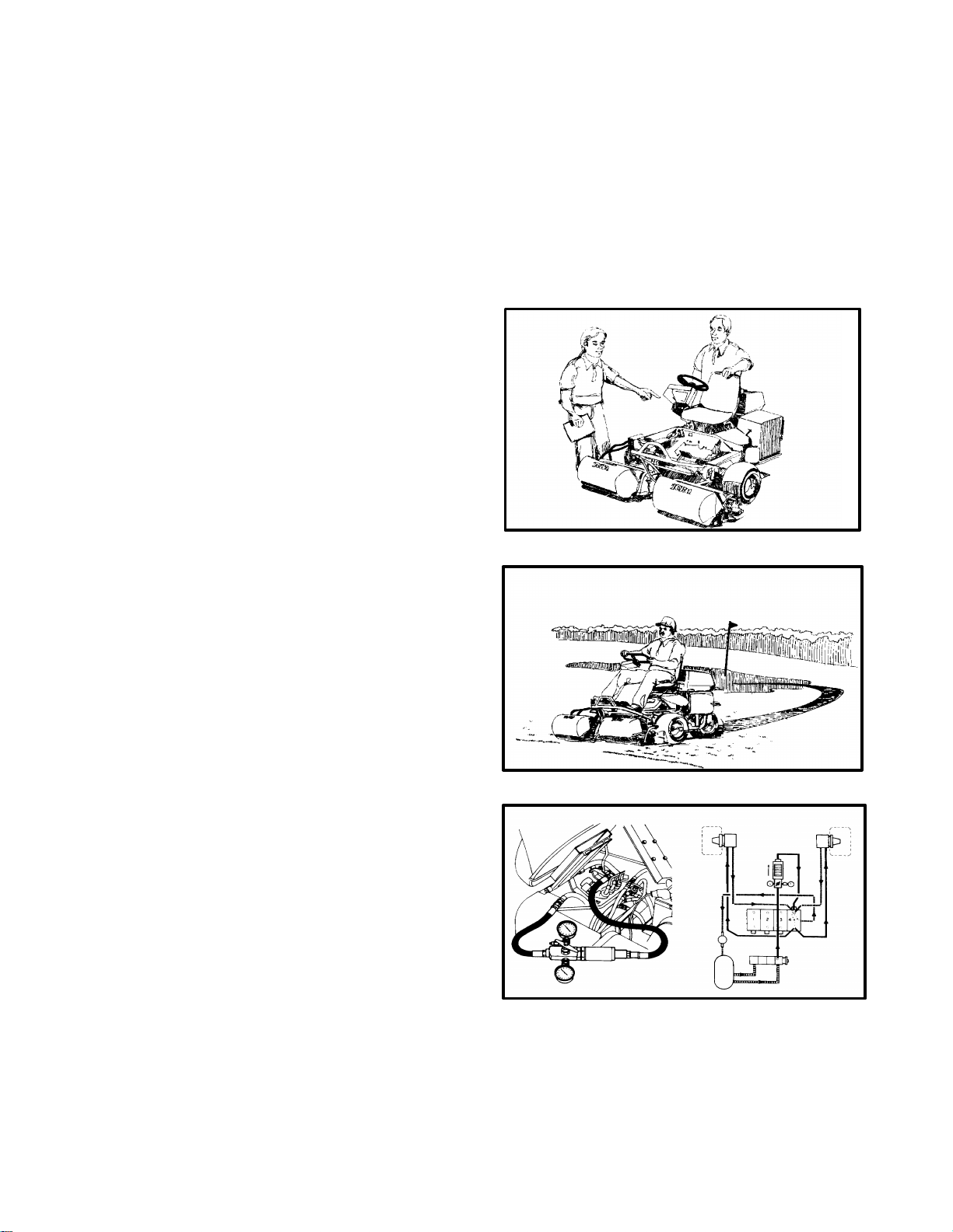
Principles of Hydraulic Test Equipment
A hydraulic system with an excessive increase in
heat or noise is a potential failure. Should either of
these conditions be noticed, immediately stop the
machine, turn off the engine, locate the cause of
the trouble, and correct it before allowing the machine to be used again. Continued use of an improperly functioning hydraulic system could lead to
extensive internal damage.
When troubleshooting a hydraulic problem:
1. Know the hydraulic system for the machine:
• Study the schematics, Operators Manual and
Service Manual.
• Know how the system works and what the relief valve setting and the pump output should
be.
2. Talk to the operator:
• How did the machine act just as it started to
malfunction?
• Was any “do-it-yourself” service performed or
did anyone else attempt to repair the machine?
• How was the machine used and when was
maintenance last performed?
3. Operate the machine:
• Operate the machine in conditions simulating
when the malfunction occurred. Verify what
the operator described.
• Are the gauges and warning lights operating
correctly.
• Do the controls feel spongy or stick.
• Check for any unusual sounds, smells, or
smoke. At what speed or operating cycles
does this occur.
4. Inspect the machine:
• Check the hydraulic fluid level and condition.
Is the fluid dirty or filters plugged?
• Check for overheating. Does the oil have a
burnt odor? Is the oil cooler plugged or lines
caked with dirt?
• Look for bent or collapsed fluid lines. Check
for leaks, loose fasteners, cracked welds,
binding pivot points, damaged linkage, etc.
5. List possible causes:
• Note what was reported by the operator and
verified by you.
• List what you found during your inspection.
• Remember that there may be more than one
cause leading to the failure or malfunction.
6. Determine which cause is most likely the problem:
• Look at your list of most possible causes and
determine which are the most likely. Use the
troubleshooting charts in the Service Manual.
7. Test your findings
• Operate the machine with a hydraulic tester
connected to the suspected malfunctioning
circuit.
• It may be necessary to replace or adjust a
component to verify your findings.
Figure 1
Figure 2
Figure 3
23
Page 26
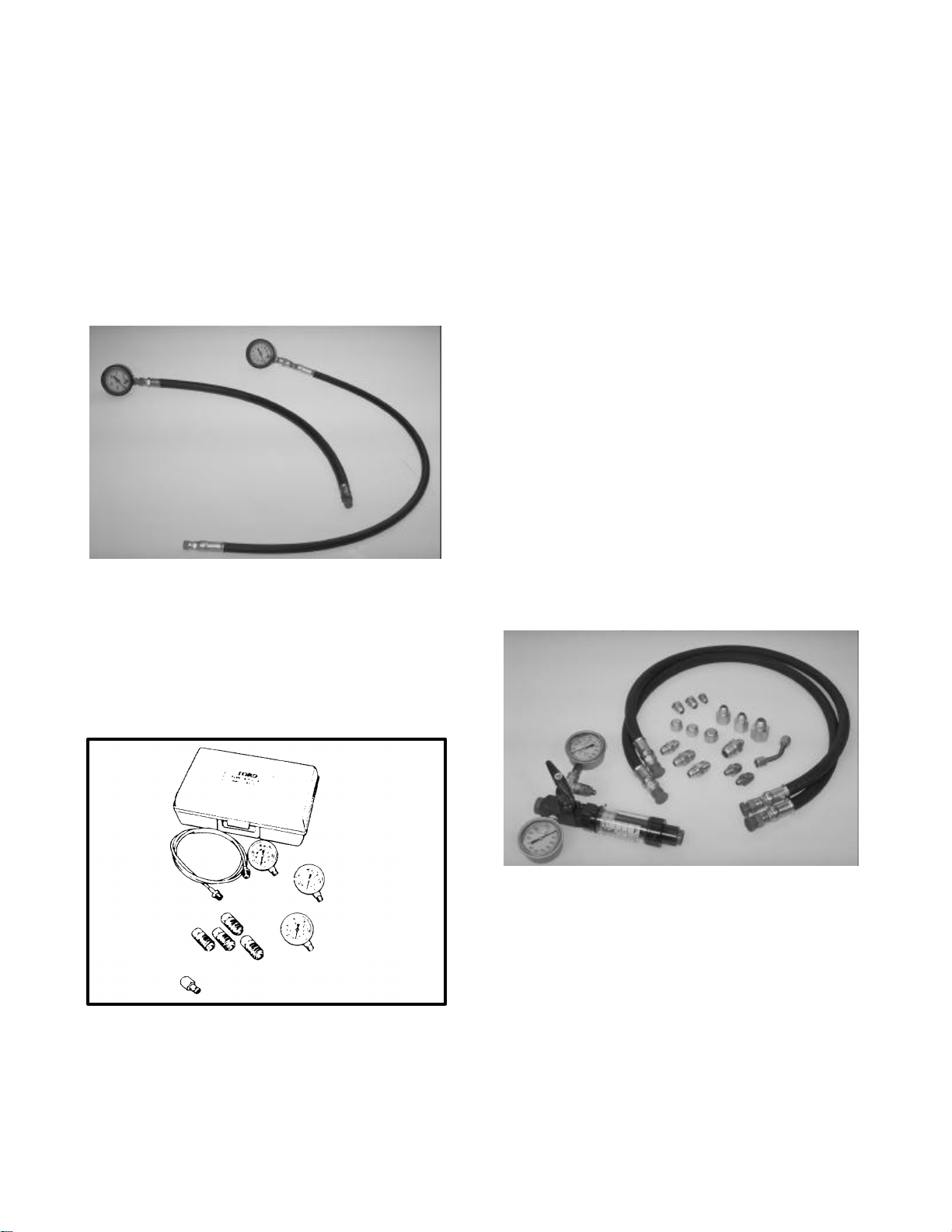
Hydraulic test equipment allows you to observe the
amount of oil pressure and oil flow in a circuit under
various conditions.
Hydraulic testers may vary significantly in size,
construction, accuracy, and cost. The decision as to
which tester to purchase should be influenced by
what type of tests will be performed on all the hydraulically powered equipment in the shop.
Hydraulic Tester
(With Pressure and Flow Capabilities)
1. INLET HOSE: Hose connected from the system
circuit to the inlet side of the tester.
2. LOAD VALVE: If required, upon turning the
valve to restrict flow, a simulated working load is
created in the circuit.
High And Low Pressure Test Gauges
Low pressure gauge 1000 PSI, high pressure gauge
5000 PSI, and associated hoses and fittings.
Figure 4
Hydraulic Pressure Gauges
(Quick Disconnect type)
For use on Toro machines that have test ports with
quick disconnect adapters. 1000, 5000, and 10,000
PSI gauges with extension hose and quick disconnect fittings.
3. LOW PRESSURE GAUGE: Low range gauge to
provide accurate readings at low pressure, 0-1000
PSI.
This gauge has a protector valve which
cuts out when pressure is about to exceed
the normal range for the gauge. The cutout
pressure is adjustable.
4. HIGH PRESSURE GAUGE: High range gauge to
accommodate pressure beyond the capacity of the
low pressure gauge, 0 - 5000 PSI.
5. FLOW METER: This meter measures actual oil
flow in the operating circuit. The reading is given in
gallons per minute (GPM) with a gauge rated at 15
GPM.
6. OUTLET HOSE: Hose from the outlet side of the
hydraulic tester to be connected the hydraulic
circuit.
Figure 5
Figure 6
24
Page 27
Before Performing Hydraulic Tests
ALL OBVIOUS AREAS SUCH AS OIL SUPPLY,
FILTERS, IMPROPER ADJUSTMENT BINDING
LINKAGE, OR LOOSE FASTENERS MUST BE
CHECKED BEFORE ASSUMING THAT A HYDRAULIC COMPONENT IS THE SOURCE OF
THE PROBLEM BEING EXPERIENCED.
1. Thoroughly clean the machine before disconnecting or disassembling any hydraulic components. Always keep in mind the need for cleanliness when working on hydraulic equipment.
turning it counter clockwise (tester with pressure
and flow capabilities).
IMPORTANT: Pumps used on Toro equipment
are of a positive displacement type. If a tester is
installed in a portion of the circuit not protected
by a relief valve and the pumps output flow is
completely restricted or stopped, damage to the
pump or other components could occur.
6. Install fittings finger tight, far enough to insure
that they are not cross-threaded, before tightening
them with a wrench.
2. Put caps or plugs on any hydraulic lines left open
or exposed during testing or removal of components.
3. The engine must be in good operating condition.
Always use a tachometer when doing a hydraulic
test. ENGINE SPEED WILL AFFECT THE ACCURACY OF THE TESTER READINGS.
4. To prevent damage to the tester or components,
the inlet and outlet hoses must be properly connected and not reversed (tester with pressure and
flow capabilities).
5. To minimize the possibility of damaging the
components, completely open the load valve by
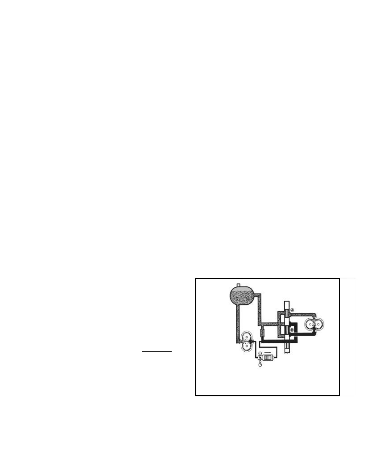
HOOK UP NO. 1
TEST A: PUMP FLOW
7. Position the tester hoses so that rotating machine parts will not make contact with them and result in hose damage.
8. Check the oil level in the reservoir.
9. Check the control linkage for improper adjustment, binding or broken parts.
10. All hydraulic test should be made with the hydraulic system at normal operating temperature.
11. Use gauges of proper pressure ratings when
performing hydraulic tests.
12. Always keep safety in mind while performing
tests. Keep bystanders away from the equipment.
Connect the tester in series with the pump output
circuit, (Fig 7) and shift the spool valve to the neutral (off) position, we can then measure the pump
output to insure that the oil flow is adequate to
drive the motor at the desired speed. Use extreme
caution when using this procedure. There is no
relief valve between the pump and the restrictor
valve when tested in this manner. Be absolutely
sure the flow meter is open when starting the
engine.
TEST B: MECHANICAL BINDING
Using the same hookup as in test A, if we shift the
spool valve to the run position, we can observe the
pressure gauge reading and verify the pressure required to rotate the hydraulic motor.
Figure 7
25
Page 28
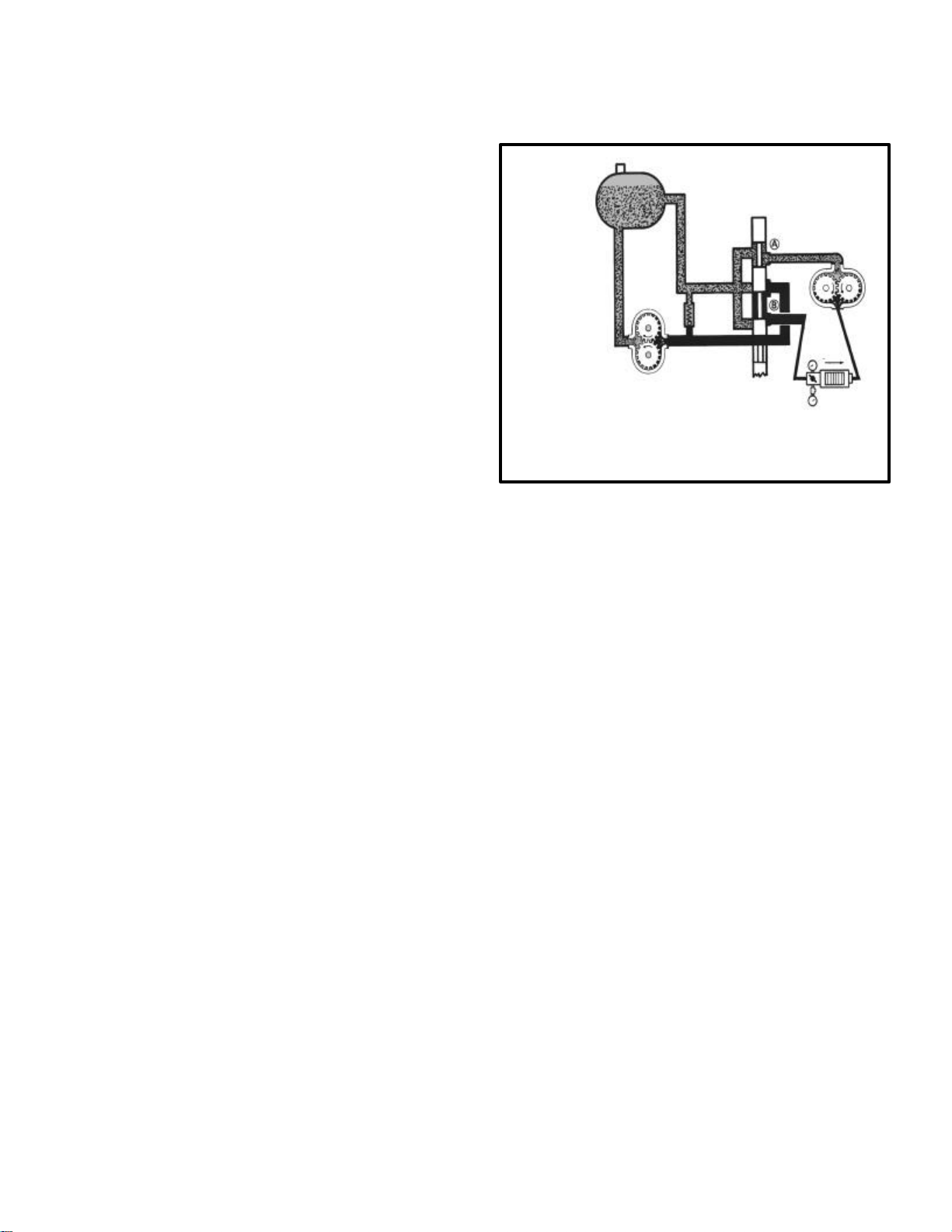
HOOK UP NO. 2
TEST A: FLOW TO MOTOR
With the control valve in the run position and the
flow meter in series between the control valve and
the motor, (Fig 8) we can measure the flow to the
motor and compare this reading with the reading
we had previously observed in Hookup No. 1, Test
A. If this reading is now lower, it indicates a problem in the spool valve or oil leakage past the relief
valve.
TEST B: RELIEF VALVE SETTING
With the control valve set in the run position, we
can close off the restrictor valve to observe the
pressure when the relief valve opens. If this pressure is below specifications, the relief valve should
be checked or repaired.
TEST C: MOTOR EFFICIENCY
If we lock the motor to prevent rotation, there
should be no flow through the motor, and this
should be indicated by the flow meter. If there is
flow and it is above an acceptable level, this indicates leakage through the motor.
Figure 8
NOTES
_________________________________________________
_________________________________________________
_________________________________________________
_________________________________________________
_________________________________________________
_________________________________________________
_________________________________________________
_________________________________________________
_________________________________________________
_________________________________________________
_________________________________________________
_________________________________________________
_________________________________________________
_________________________________________________
26
Page 29
REVIEW QUESTIONS
Answer the following review questions.
1: A larger displacement pump operating at
the same speed will:
A: Move more oil
B: Move less oil.
C: Displacement has no effect on
oil flow.
2: When a open center spool valve is in the
neutral position:
A. All oil flow stops.
B. Oil flows back to reservoir.
C: Oil flows to lower port.
D: Oil flows to raise port.
3: The o-rings on a solenoid valve are
matched to the valve and should never
be replaced.
A: True
B: False
4: The hydraulic oil pump supplies the
system with:
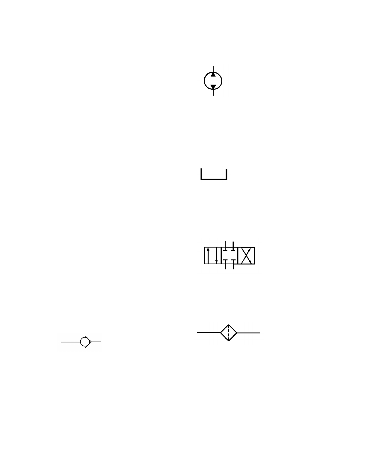
7: The following symbol is:
A: Oil Cooler.
B: Reversible Hydraulic
Motor.
C: Combination pump\motor.
D: Reversible Hydraulic
Pump.
8: The following symbol is:
A: Vented Reservoir.
B: Pressurized Reservoir.
C: Open Center Valve.
D: Operators Manual Box.
9: The following symbol is:
A: Oil flow, ( gpm )
B: Oil pressure ( psi )
C: Non of the above
5: The increase in mechanical advantage in
a hydraulic system is affected by:
A: The rate of oil flow
B: The diameter of the pistons.
C: The relief valve setting.
D: all of the above.
6: The following symbol is:
A : Variable speed motor.
B: Check Valve.
C: Orifice.
D: Accumulator.
A: 3 Position Valve.
B: Closed Center Valve.
C: All Of The Above.
10: The following symbol is:
A: Oil Cooler.
B: Oil Filter.
C: Flow restrictor.
D: None Of The Above
27
Page 30

REVIEW QUESTIONS
11: A Hydrostatic Drive pump is:
A: Fixed displacement.
B: Variable displacement.
C: Driven by the wheels.
12: The purpose of the charge
pressure circuit is:
A: Pressurize the hydraulic
filter.
B: Replenish internal oil
leakage in drive circuit.
C: Pressurize transaxle case
to keep dirt out.
D: Keep battery charged
E: Supply pressurized oil to
the rotating group, keeping the
slippers against the swash plate.
F: Both B & E.
G: None of the above.
13: A hydraulic motor converts fluid energy
into rotational movement.
A: True.
B: False.
14: Never use your hands to try and find a
hydraulic oil leak.
A: True.
B: False.
15: F.F.F.T is
16: A properly installed hose will have a 45º
twist in the hose.
A: True
B: False
17: Fitting O-rings should always be
installed dry.
A: True
B: False
18: When checking pump flow:
A: Completely restrict pump flow.
B: Use extreme caution if tester is
ahead of relief valve.
C: Connect tester in series with
the system.
D: Both B & C.
19: Hydraulic test should be conducted
with:
A: The reservoir full of oil.
B: The hydraulic system at normal
operating temperature.
C: The proper size gauges installed.
D: All of the above.
20: The units engine has no effect on
hydraulic tests.
A: True
B: False
A: Fractional Fitting Face Turns
B: Fitting Face Flat Turns
C: Flats From Finger Tight
D: None of the above
28
Page 31

Page 32

Commercial Products
© The Toro Company
 Loading...