

Page 1
FormNo.3362-759RevB
TRX-15,TRX-19,andTRX-26
Trencher
ModelNo.22970—SerialNo.310000001andUp
ModelNo.22970G—SerialNo.310000001andUp
ModelNo.22971—SerialNo.310000001andUp
ModelNo.22971G—SerialNo.310000001andUp
ModelNo.22974—SerialNo.310000001andUp
ToregisteryourproductordownloadanOperator'sManualorPartsCatalogatnocharge,gotowww.T oro.com.OriginalInstructions(EN)
Page 2
Thismachineisdesignedtodigtrenchesinsoiltobury
G007797
1
cablingandpipingforvariousapplications.Itisnot
intendedtocutrock,wood,oranyothermaterialother
thansoil.
Warning
Introduction
Readthisinformationcarefullytolearnhowtooperate
andmaintainyourproductproperlyandtoavoidinjury
andproductdamage.Youareresponsibleforoperating
theproductproperlyandsafely.
CALIFORNIA
Proposition65Warning
Theengineexhaustfromthisproduct
containschemicalsknowntotheStateof
Californiatocausecancer,birthdefects,
orotherreproductiveharm.
Theremaybeburiedpower,gas,and/or
telephonelinesintheworkarea.Shockor
explosionmayoccurifyoudigintothem.
Havethepropertyorworkareamarkedfor
buriedlinesanddonotdiginmarkedareas.
Contactyourlocalmarkingserviceorutility
companytohavethepropertymarked(for
example,intheUnitedStates,call811forthe
nationwidemarkingservice).
ThissparkignitionsystemcomplieswithCanadian
ICES-002.
Important:Thisengineisnotequippedwitha
sparkarrestermufer.ItisaviolationofCalifornia
PublicResourceCodeSection4442touseoroperate
theengineonanyforest-covered,brush-covered,or
grass-coveredland.Otherstatesorfederalareas
mayhavesimilarlaws.
YoumaycontactTorodirectlyatwww .T oro.comfor
productandaccessoryinformation,helpndinga
dealer,ortoregisteryourproduct.
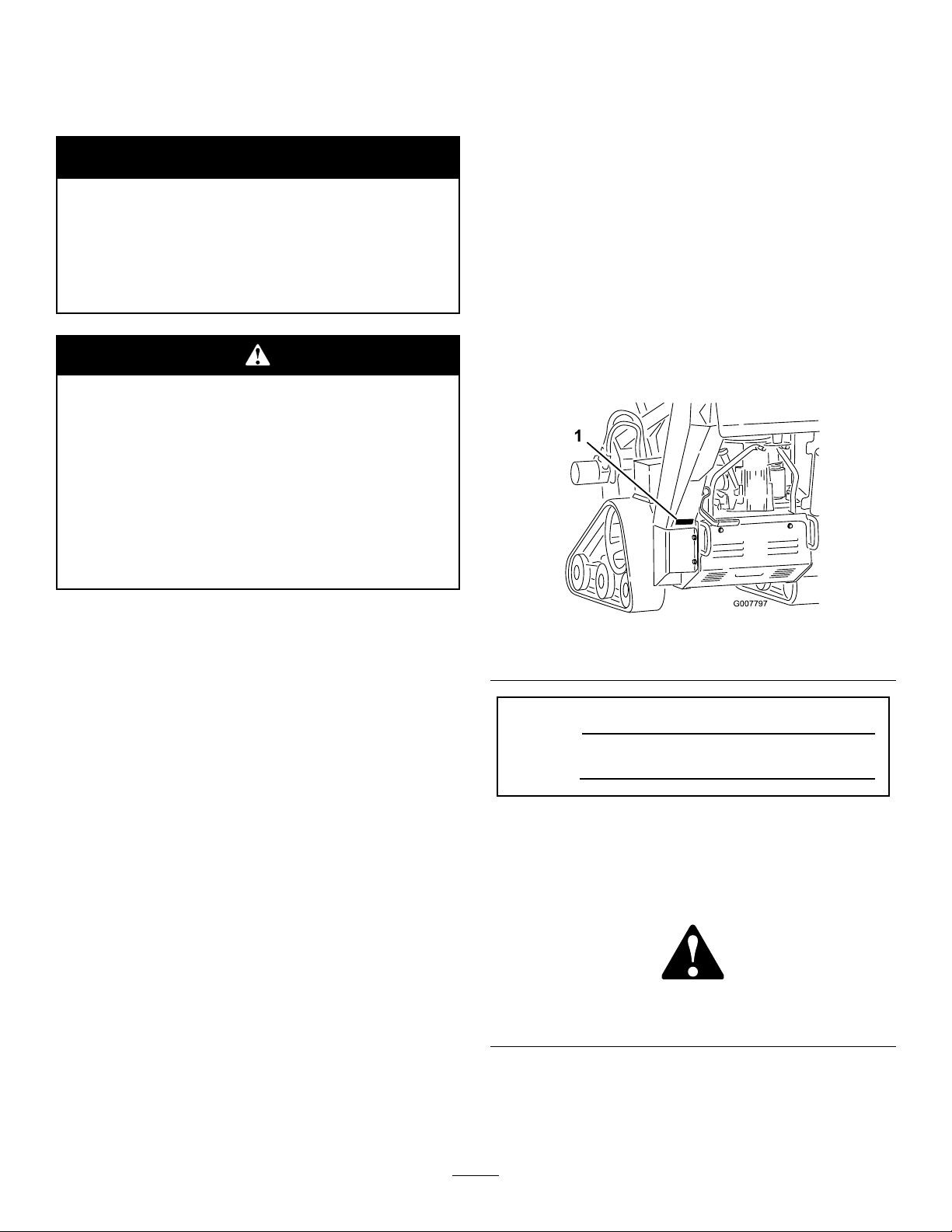
Wheneveryouneedservice,genuineToroparts,or
additionalinformation,contactanAuthorizedService
DealerorToroCustomerServiceandhavethemodel
andserialnumbersofyourproductready.Figure1
illustratesthelocationofthemodelandserialnumbers
ontheproduct.Writethenumbersinthespace
provided.
Figure1
1.Modelandserialnumberplate
ModelNo.
SerialNo.
Theenclosed
Engine Owner’ s Man ual
forinformationregardingtheUSEnvironmental
ProtectionAgency(EPA)andtheCalifornia
EmissionControlRegulationofemissionsystems,
maintenance,andwarranty.Replacementsmaybe
orderedthroughtheenginemanufacturer.
issupplied
Thismanualidentiespotentialhazardsandhas
safetymessagesidentiedbythesafetyalertsymbol
(Figure2),whichsignalsahazardthatmaycauseserious
injuryordeathifyoudonotfollowtherecommended
precautions.
ThisproductcomplieswithallrelevantEuropean
directives,fordetailspleaseseetheseparateproduct
specicDeclarationofConformity(DOC)sheet.
1.Safetyalertsymbol
Figure2
Thismanualuses2otherwordstohighlightinformation.
Importantcallsattentiontospecialmechanical
informationandNoteemphasizesgeneralinformation
worthyofspecialattention.
©2009—TheT oro®Company
8111LyndaleAvenueSouth
Bloomington,MN55420
2
Contactusatwww.Toro.com.
PrintedintheUSA.
AllRightsReserved
Page 3

Contents
Introduction.................................................................2
Safety...........................................................................4
SafeOperatingPractices.......................................4
SoundPressure.....................................................6
SoundPower........................................................6
Vibration..............................................................6
SlopeIndicator.....................................................8
SafetyandInstructionalDecals.............................9
Setup..........................................................................12
1InstallingtheBoomandChain.........................12
2CheckingFluidLevels......................................13
3ChargingtheBattery(ElectricStartModels
Only)..............................................................13
ProductOverview......................................................13
Controls.............................................................13
Specications.....................................................16
Attachments/Accessories...................................16
Operation...................................................................16
AddingFuel.......................................................16
CheckingtheEngineOilLevel............................17
CheckingtheHydraulicFluidLevel.....................18
StartingandStoppingtheEngine........................19
StoppingtheMachine.........................................20
MovingaNon-functioningMachine...................20
DiggingaTrench................................................20
SecuringtheMachineforTransport....................20
LiftingtheMachine............................................21
OperatingTips...................................................21
Maintenance...............................................................22
RecommendedMaintenanceSchedule(s)................22
PremaintenanceProcedures....................................23
RemovingtheCoverPlate...................................23
InstallingtheCoverPlate....................................23
RemovingtheBottomShield..............................23
InstallingtheBottomShield................................23
Lubrication.............................................................24
GreasingtheMachine.........................................24
GreasingtheTrencherHousing..........................24
EngineMaintenance...............................................25
ServicingtheAirCleaner(Models22970and
22971)............................................................25
ServicingtheAirCleaner(Model22974)..............26
ServicingtheEngineOil.....................................27
ServicingtheSparkPlug.....................................28
FuelSystemMaintenance.......................................30
DrainingtheFuelTank.......................................30
ReplacingtheFuelFilter.....................................30
ElectricalSystemMaintenance................................31
ServicingtheBattery(Models22971and
22974)............................................................31
ReplacingtheFuses(Models22971and
22974)............................................................33
DriveSystemMaintenance.....................................34
ServicingtheTracks............................................34
BeltMaintenance....................................................36
ReplacingthePumpDriveBelt...........................36
ControlsSystemMaintenance.................................37
AdjustingtheTractionControl
Alignment......................................................37
AdjustingtheTractionControlNeutral
Position..........................................................38
AdjustingtheTrackingoftheTraction
Control,FullForwardPosition........................38
HydraulicSystemMaintenance...............................39
ReplacingtheHydraulicFilter.............................39
ChangingtheHydraulicFluid.............................39
CheckingtheHydraulicLines.............................40
TrencherMaintenance............................................40
ReplacingtheDiggingTeeth...............................40
CheckingandAdjustingtheDiggingChain
andBoom......................................................40
ReplacingtheDriveSprocket..............................41
Cleaning.................................................................42
RemovingDebrisfromtheMachine....................42
Storage.......................................................................43
Troubleshooting.........................................................44
Schematics.................................................................46
3
Page 4

Safety
Improperuseormaintenancebytheoperator
orownercanresultininjury.Toreducethe
potentialforinjury,complywiththesesafety
instructionsandalwayspayattentiontothesafety
alertsymbol,whichmeans:
Danger
complywiththeinstructionmayresultinpersonal
injuryordeath.
—personalsafetyinstruction.Failureto
Caution
SafeOperatingPractices
Thisproductiscapableofamputatinghandsandfeet.
Alwaysfollowallsafetyinstructionstoavoidserious
injuryordeath.
,
W ar ning
•Inspecttheareawheretheequipmentistobeused
andremoveallobjectssuchasrocks,toys,andwire
whichcanbethrownbythemachine.
•Useextracarewhenhandlinggasolineandother
fuels.Theyareammableandvaporsareexplosive.
,or
–Useonlyanapprovedcontainer
–Neverremovethegascaporaddfuelwiththe
enginerunning.Allowtheenginetocoolbefore
refueling.Donotsmoke.
–Neverrefuelordrainthemachineindoors.
•Checkthattheoperatorpresencecontrols,safety
switches,andshieldsareattachedandfunctioning
properly.Donotoperateunlesstheyarefunctioning
properly.
Operation
Engineexhaustcontainscarbonmonoxide,an
odorless,deadlypoisonthatcankillyou.
Donotruntheengineindoorsorinanenclosed
area.
Training
•ReadtheOperator’sManualandothertraining
material.Iftheoperator(s)ormechanic(s)can
notreadEnglish,itistheowner’sresponsibilityto
explainthismaterialtothem.
•Becomefamiliarwiththesafeoperationofthe
equipment,operatorcontrols,andsafetysigns.
•Alloperatorsandmechanicsshouldbetrained.The
ownerisresponsiblefortrainingtheusers.
•Neverletchildrenoruntrainedpeopleoperateor
servicetheequipment.Localregulationsmayrestrict
theageoftheoperator.
•Theowner/usercanpreventandisresponsiblefor
accidentsorinjuriesoccurringtohimselforherself,
otherpeopleorproperty.
Preparation
•Evaluatetheterraintodeterminewhataccessories
andattachmentsareneededtoproperlyand
safelyperformthejob.Onlyuseaccessoriesand
attachmentsapprovedbythemanufacturer.
•Wearappropriateclothingincludinghardhat,
safetyglasses,longpants,safetyshoes,andhearing
protection.Longhair,looseclothingorjewelrymay
gettangledinmovingparts.
•Neverrunanengineinanenclosedarea.
•Onlyoperateingoodlight,keepingawayfromholes
andhiddenhazards.
•Besurealldrivesareinneutralandtheparkingbrake
isengagedbeforestartingtheengine.Onlystartthe
enginefromtheoperator’sposition.
•Slowdownanduseextracareonhillsides.Besure
totravelintherecommendeddirectiononhillsides.
Turfconditionscanaffectthemachine’sstability.
•Slowdownandusecautionwhenmakingturnsand
whenchangingdirectionsonslopes.
•Neveroperatewiththeguardsnotsecurelyinplace.
Besureallinterlocksareattached,adjustedproperly,
andfunctioningproperly.
•Donotchangetheenginegovernorsettingor
overspeedtheengine.
•Stoponlevelground,lowertheboom,disengage
thetrencherhydraulics,engagetheparkingbrake,
andshutofftheenginebeforeleavingtheoperator’ s
positionforanyreason.
•Keephandsandfeetawayfromthemovingchain,
diggingteeth,andspoilsauger.
•Lookbehindanddownbeforebackinguptobesure
ofaclearpath.
•Nevercarrypassengersandkeeppetsandbystanders
away.
•Slowdownandusecautionwhenmakingturnsand
crossingroadsandsidewalks.
•Donotoperatethemachineundertheinuenceof
alcoholordrugs.
4
Page 5

•Usecarewhenloadingorunloadingthemachine
intoatrailerortruck.
•Usecarewhenapproachingblindcorners,shrubs,
trees,orotherobjectsthatmayobscurevision.
•Ensurethattheareaisclearofotherpeoplebefore
operatingthemachine.Stopthemachineifanyone
entersthearea.
•Neverleavearunningmachineunattended.Always
lowertheboom,stoptheengine,settheparking
brake,andremovethekeybeforeleaving.
•Neverjerkthecontrols;useasteadymotion.
•Watchfortrafcwhenoperatingnearorcrossing
roadways.
•Removeobstaclessuchasrocks,treelimbs,etc.
fromtheworkarea.Watchforholes,ruts,orbumps,
asuneventerraincouldoverturnthemachine.Tall
grasscanhideobstacles.
•UseonlyToro-approvedaccessories.Accessoriescan
changethestabilityandtheoperatingcharacteristics
ofthemachine.Warrantymaybevoidedifusedwith
unapprovedaccessories.
•Keepallmovementsonslopesslowandgradual.Do
notmakesuddenchangesinspeedordirection.
•Avoidstartingorstoppingonaslope.Ifthemachine
losestraction,proceedslowly,straightdownthe
slope.
•Donottouchpartswhichmaybehotfrom
operation.Allowthemtocoolbeforeattemptingto
maintain,adjust,orservice.
•Ensurethatyouoperatethemachineinareaswhere
therearenoobstaclesincloseproximitytothe
operator.Failuretomaintainadequatedistancefrom
trees,walls,andotherbarriersmayresultininjury
asthemachinebacksupduringoperationifthe
operatorisnotattentivetothesurroundings.Only
operatetheunitinareaswherethereissufcient
clearancefortheoperatortosafelymaneuverthe
product.
•Beforedigging,havetheareamarkedfor
undergroundutilities,anddonotdiginmarkedareas.
•Locatethepinchpointareasmarkedonthemachine
andkeephandsandfeetawayfromtheseareas.
•Lightningcancausesevereinjuryordeath.If
lightningisseenorthunderisheardinthearea,do
notoperatethemachine;seekshelter.
SlopeOperation
Slopesareamajorfactorrelatedtoloss-of-controland
tip-overaccidents,whichcanresultinsevereinjuryor
death.Allslopesrequireextracaution.
•Donotoperatethemachineonhillsidesorslopes
exceedingtheanglesrecommendedinthefollowing
table.
ModelFrontFacing
22970
22971
22974
Uphill
15°14°19°
13°14°19°
11°11°16°
Note:Seealsothe,page.
•Operateupanddownslopeswiththefrontend
ofthemachineuphill.
RearFacing
Uphill
SideFacing
Uphill
•Avoidturningonslopes.Ifyoumustturn,turn
slowlyandkeeptheheavyendofthemachineuphill.
•Donotoperateneardrop-offs,ditches,or
embankments.Themachinecouldsuddenlyturn
overifatrackgoesovertheedgeofaclifforditch,
orifanedgecavesin.
•Donotoperateonwetgrass.Reducedtractioncould
causesliding.
•Donotparkthemachineonahillsideorslope
withoutloweringtheboomtotheground,setting
theparkingbrake,andchockingthetracks.
MaintenanceandStorage
•Disengagethetrencherhydraulics,lowertheboom,
settheparkingbrake,stoptheengine,andremove
thekey .Waitforallmovementtostopbefore
adjusting,cleaning,orrepairing.
•Cleandebrisfromthechain,diggingteeth,boom,
trencherhead,drives,mufers,andenginetohelp
preventres.Cleanupoilorfuelspillage.
•Lettheenginecoolbeforestoringanddonotstore
nearame.
•Donotstorefuelnearamesordrainindoors.
•Parkthemachineonlevelground.Neverallow
untrainedpersonneltoservicethemachine.
•Usejackstandstosupportcomponentswhen
required.
•Carefullyreleasepressurefromcomponentswith
storedenergy.
•Disconnectthebattery(electricstartmodelsonly)
orremovethesparkplugwiresbeforemaking
anyrepairs.Disconnectthenegativeterminalrst
andthepositivelast.Reconnectpositiverstand
negativelast.
5
Page 6

•Keephandsandfeetawayfrommovingparts.If
possible,donotmakeadjustmentswiththeengine
running.
•Keepallpartsingoodworkingconditionandall
hardwaretightened.Replaceallwornordamaged
decals.
•Keepnutsandboltstight.Keepequipmentingood
condition.
•Nevertamperwithsafetydevices.
•Keepthemachinefreeofgrass,leaves,orother
debrisbuild-up.Cleanupoilorfuelspillage.Allow
themachinetocoolbeforestoring.
•Useextracarewhenhandlinggasolineandother
fuels.Theyareammableandvaporsareexplosive.
–Useonlyanapprovedcontainer.
–Neverremovethegascaporaddfuelwhen
theengineisrunning.Allowtheenginetocool
beforerefueling.Donotsmoke.
–Neverrefuelthemachineindoors.
–Neverstorethemachineorfuelcontainerinside
wherethereisanopename,suchasneara
waterheaterorfurnace.
–Neverllacontainerwhileitisinsideavehicle,
trunk,pick-upbed,oranysurfaceotherthanthe
ground.
–Keepcontainernozzleincontactwiththetank
duringlling.
•Stopandinspecttheequipmentifyoustrikean
object.Makeanynecessaryrepairsbeforerestarting.
•UseonlygenuineT ororeplacementpartstoensure
thatoriginalstandardsaremaintained.
•Batterysafety(electricstartmodelsonly):
–Chargebatteriesinanopen,wellventilated
area,awayfromsparkandames.Unplugthe
chargerbeforeconnectingordisconnectingit
fromthebattery.Wearprotectiveclothingand
useinsulatedtools.
–Batteryacidispoisonousandcancauseburns.
Avoidcontactwithskin,eyes,andclothing.
Protectyourface,eyes,andclothingwhen
workingwithabattery.
–Batterygasescanexplode.Keepcigarettes,
sparksandamesawayfromthebattery.
•Keepyourbodyandhandsawayfrompinhole
leaksornozzlesthatejecthighpressurehydraulic
uid.Usecardboardorpapertondhydraulic
leaks;neveruseyourhands.Hydraulicuidescaping
underpressurecanpenetrateskinandcauseinjury
requiringsurgerywithinafewhoursbyaqualied
surgeonorgangrenemayresult.
SoundPressure
Model22970and22971
Thisunithasasoundpressurelevelattheoperator’s
earof91dBA,whichincludesanUncertaintyValue(K)
of1.0dBA.
Soundpressurelevelwasdeterminedaccordingtothe
proceduresoutlinedinENISO11201.
Model22974
Thisunithasasoundpressurelevelattheoperator’s
earof92dBA,whichincludesanUncertaintyValue(K)
of1.0dBA.
Soundpressurelevelwasdeterminedaccordingtothe
proceduresoutlinedinENISO11201.
SoundPower
Model22970and22971
Thisunithasaguaranteedsoundpowerlevelof105
dBA,whichincludesanUncertaintyValue(K)of3.75
dBA.
Soundpowerlevelwasdeterminedaccordingtothe
proceduresoutlinedinENISO3744.
Model22974
Thisunithasaguaranteedsoundpowerlevelof107
dBA,whichincludesanUncertaintyValue(K)of3.75
dBA.
Soundpowerlevelwasdeterminedaccordingtothe
proceduresoutlinedinENISO3744.
Vibration
Model22970and22971
Measuredvibrationlevelforrighthand=2.5m/s
Measuredvibrationlevelforlefthand=2.5m/s
UncertaintyValue(K)=1.25m/s
Measuredvaluesweredeterminedaccordingtothe
proceduresoutlinedinENISO20643.
2
Model22974
Measuredvibrationlevelforrighthand=1.8m/s
Measuredvibrationlevelforlefthand=2.0m/s
UncertaintyValue(K)=1.00m/s
2
2
2
2
2
6
Page 7

Measuredvaluesweredeterminedaccordingtothe
proceduresoutlinedinENISO20643.
7
Page 8
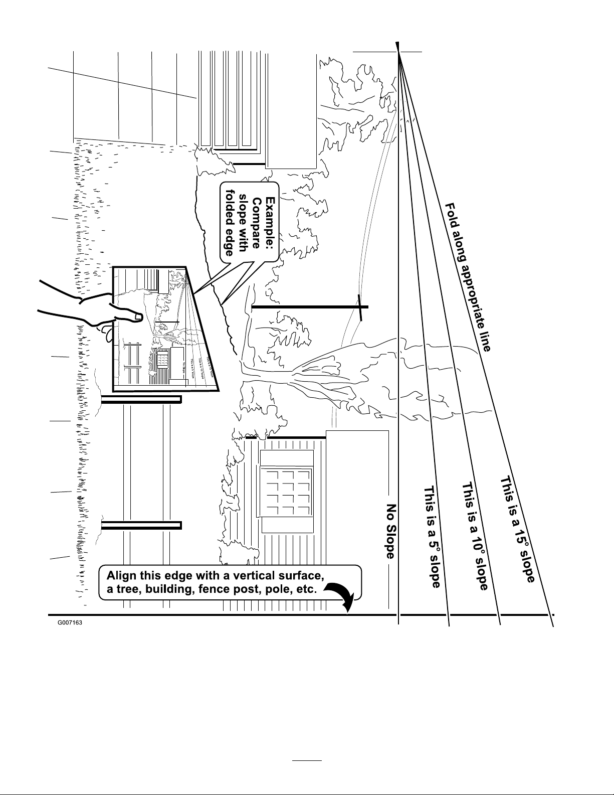
SlopeIndicator
8
Page 9
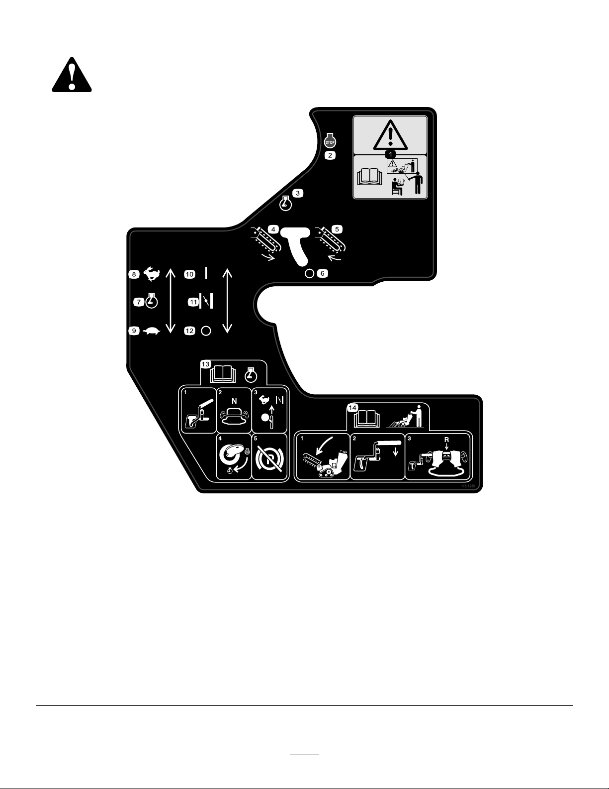
SafetyandInstructionalDecals
Safetydecalsandinstructionsareeasilyvisibletotheoperatorandarelocatednearanyareaof
potentialdanger.Replaceanydecalthatisdamagedorlost.
115-1230
1.Warning—donotoperatethismachineunlessyouaretrained.
2.Engine—stop
3.Engine—run
4.Trencherchain—reverse
5.Trencherchain—forward
6.Trencherchain—off
7.Enginethrottle
8.Fast
9.Slow
10.Choke
11.On/Closed
12.Off/Open
13.ReadtheOperator’sManualbeforestartingtheengine;tostarttheengine,movethetrenchercontrolleverintotheOffposition,
placethetractioncontrolinNeutral,movetheenginespeedtoFastandthechoketoOn/Closed,turntheignitionkeytorun,
andreleasetheparkingbrakeoncetheenginehasstarted.
14.ReadtheOperator’sManualbeforeoperatingthetrencher;tooperatethetrencher ,lowertheboom,movethetrenchercontrol
levertothereferencebar,pullthetractioncontrolrearwardtomoveinreverseanddigthetrench.
9
Page 10
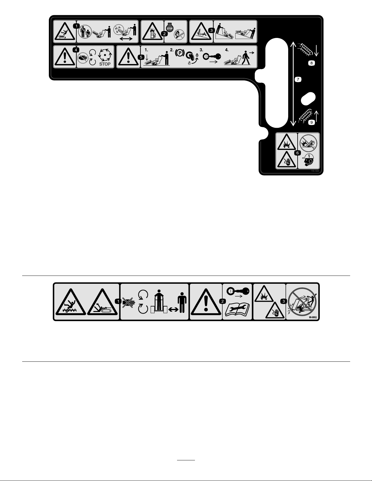
115-1231
1.Cutting/dismembermenthazardofbystanders,
trencher—keepbystandersasafedistancefromthemachine;
donotoperatethetrencherchainwhiletransportingthe
machine.
2.Explosionhazard,fueling—stoptheengineandextinguish
allameswhenfueling.
3.Tipping/crushinghazard—lowerthetrencherheadwhen
operatingonslopes.
4.Warning—stayawayfrommovingparts;waitforallmoving
partstostop
5.Warning—lowertheboom,engagetheparkingbrakeand
stoptheengine,removetheignitionkey ,beforeleavingthe
machine.
6.Explosionhazard;shockhazard—donotusemachinenear
buriedutilitylines;contacttheproperagenciesbeforedigging.
7.Boomelevation
8.Lowertheboom
9.Raisetheboom
99-9952
1.Cuttinghazard,chainandauger—stayawayfrommovingpartsandkeepbystandersawayfromthemachine.
2.Warning—stoptheengineandremovethekeybeforepreformingandmaintenanceorrepairs.
3.Explosionand/orelectricshockhazard—donotdiginareaswithburiedgasorpowerlines.
10
Page 11
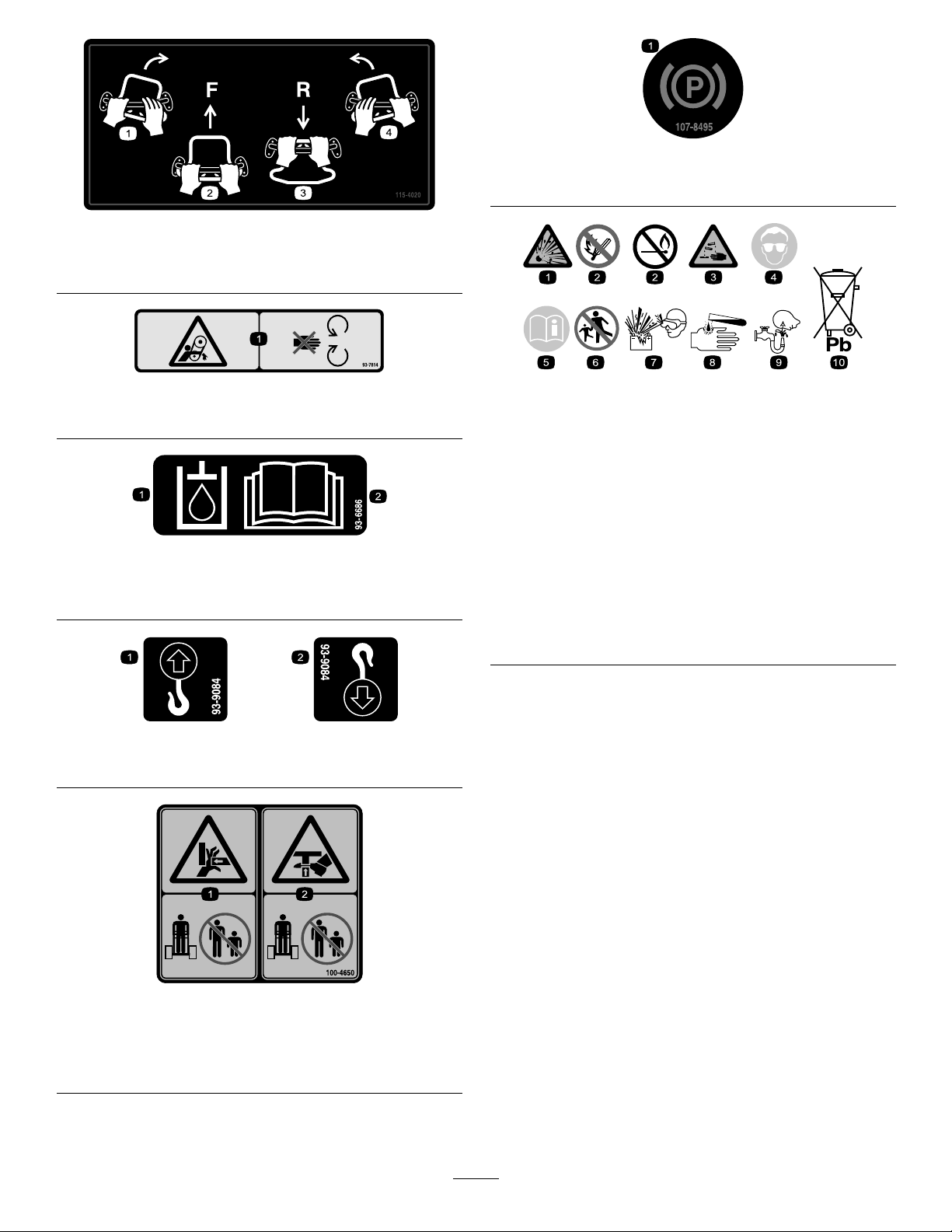
115-4020
1.Turnright3.Reverse
2.Forward
107-8495
1.Parkingbrake
4.Turnleft
93-7814
1.Entanglementhazard,belt—stayawayfrommovingparts.
93-6686
1.Hydraulicoil
2.ReadtheOperator’sManual.
93-9084
1.Liftpoint
2.Tie-downpoint
BatterySymbols
Someorallofthesesymbolsareonyourbattery(electric
startmodelsonly)
1.Explosionhazard
2.Nore,opename,or
smoking.
3.Causticliquid/chemical
burnhazard
4.Weareyeprotection9.Flusheyesimmediately
5.ReadtheOperator’s
Manual.
6.Keepbystandersasafe
distancefromthebattery .
7.Weareyeprotection;
explosivegasescan
causeblindnessandother
injuries
8.Batteryacidcancause
blindnessorsevereburns.
withwaterandgetmedical
helpfast.
10.Containslead;donot
discard.
100-4650
1.Crushinghazardofhand—keepbystandersasafedistance
fromthemachine.
2.Crushinghazardoffoot—keepbystandersasafedistance
fromthemachine.
11
Page 12
Setup
LooseParts
Usethechartbelowtoverifythatallpartshavebeenshipped.
ProcedureDescription
Boom(soldseparately)
1
2
3
Chain(soldseparately)
Nopartsrequired
Nopartsrequired
1
InstallingtheBoomandChain
Partsneededforthisprocedure:
1
Boom(soldseparately)
1
Chain(soldseparately)
Procedure
Important:Thereareseveralboomandchainsize
congurationsavailable.RefertoyouAuthorized
ServiceDealertoobtaintheappropriateboomand
chaintomeetyourrequirements.
1.Stoptheengineandremovethekey.
Qty.
1
1
–
–
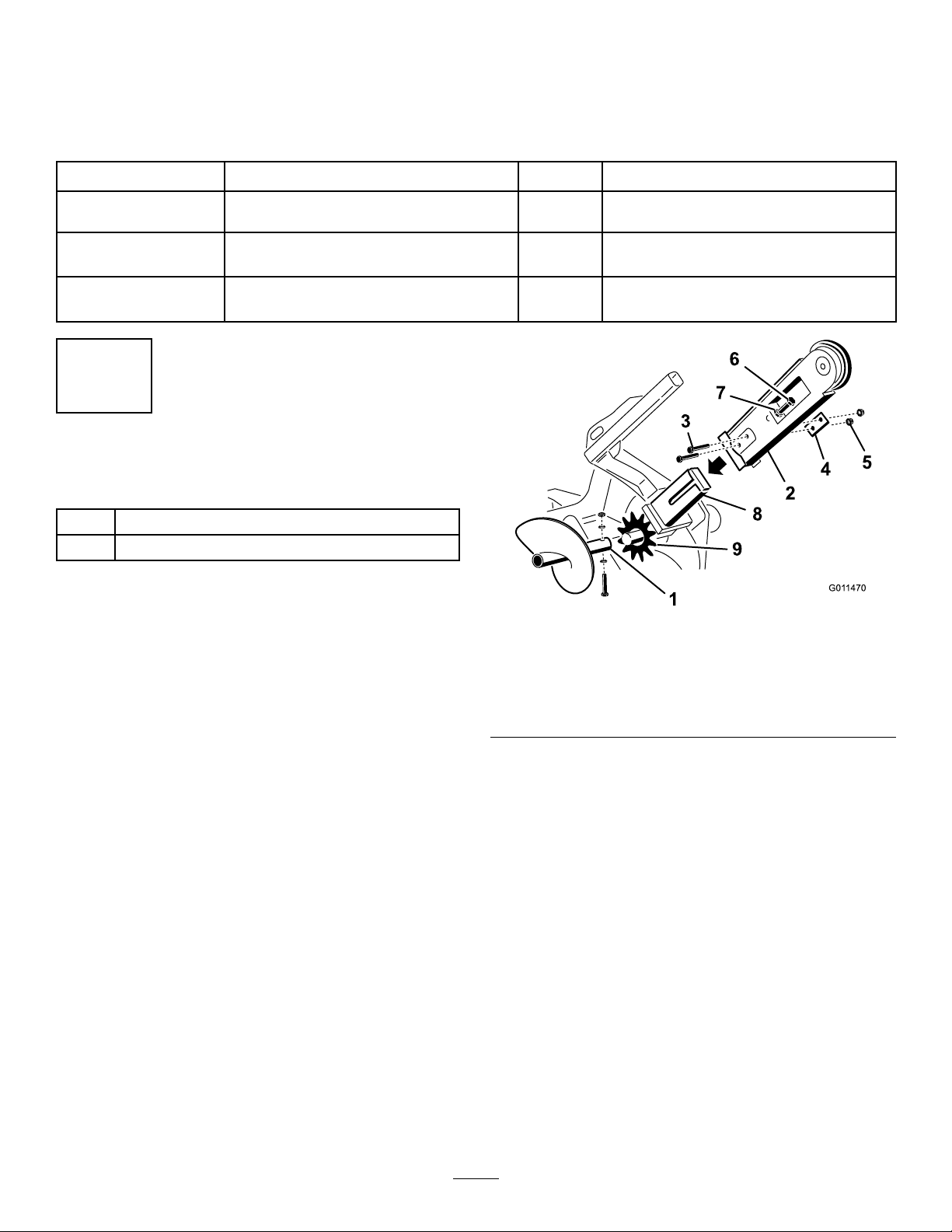
1.Spoilsauger
2.Boom7.Jamnut
3.Bolts8.Armonthedrivehead
4.Doublewasher9.Drivesprocket
5.Nuts
Installtheboomandchain.
Checktheuidlevels.
Chargethebattery .
Figure3
Use
6.Adjustingbolt
2.Removethebolt,2saddlewashers,andnutsecuring
thespoilsaugerandremovetheauger(Figure3).
Savethefastenersforfutureuse.
3.Removethe2bolts,nuts,anddoublewashersfrom
thesidesoftheboom(Figure3).
4.Loosentheadjustingboltandjamnut(Figure3).
5.Slidetheboomoverthearmonthedrivehead.
6.Installthe2bolts,nuts,anddoublewashersremoved
instep3throughtheboomandarm,butdonot
tightenthem.
7.Ifthechainisnotconnected,connectthelinksby
pressingorhammeringtheclevispinsuppliedwith
thechainthroughthelinks.
Important:T oavoidbendingthechainlinks,
placeblocksunderandbetweenthelinkswhen
hammeringtheclevispinthrough.
8.Securetheclevispinwiththecotterpinsupplied
withthechain.
12
Page 13
9.Loopthediggingchainovertheaugerdriveshaftand
G007801
5
6
783
4
1
2
ontothedrivesprocket,ensuringthatthedigging
teethpointforwardontheupperspan.
10.Settheupperspanofthechainintoplaceonthe
trencherboom,thenwrapthechainaroundthe
rollerattheendoftheboom.
11.Threadtheadjustmentboltintotheboomandturn
itinuntilthereis1-1/2to2-1/2inches(3.8to6.3
cm)ofslackinthechainonthebottomspan.
12.Threadthejamnutdowntheadjustingboltand
tightenitsecurelyagainsttheboom.
ProductOverview
13.Torquethe2boltsandnutssecuringtheboomto
135to165ft-lb(183to223N-m).
14.Installthespoilsaugerusingthebolt,2saddle
washer,andnutyouremovedpreviously.
15.Torquetheboltandnutto75ft-lb(101N-m).
2
CheckingFluidLevels
NoPartsRequired
Procedure
Beforestartingtheengineforthersttime,checkthe
engineoilandhydraulicuidlevels;refertoOperation
formoreinformation.
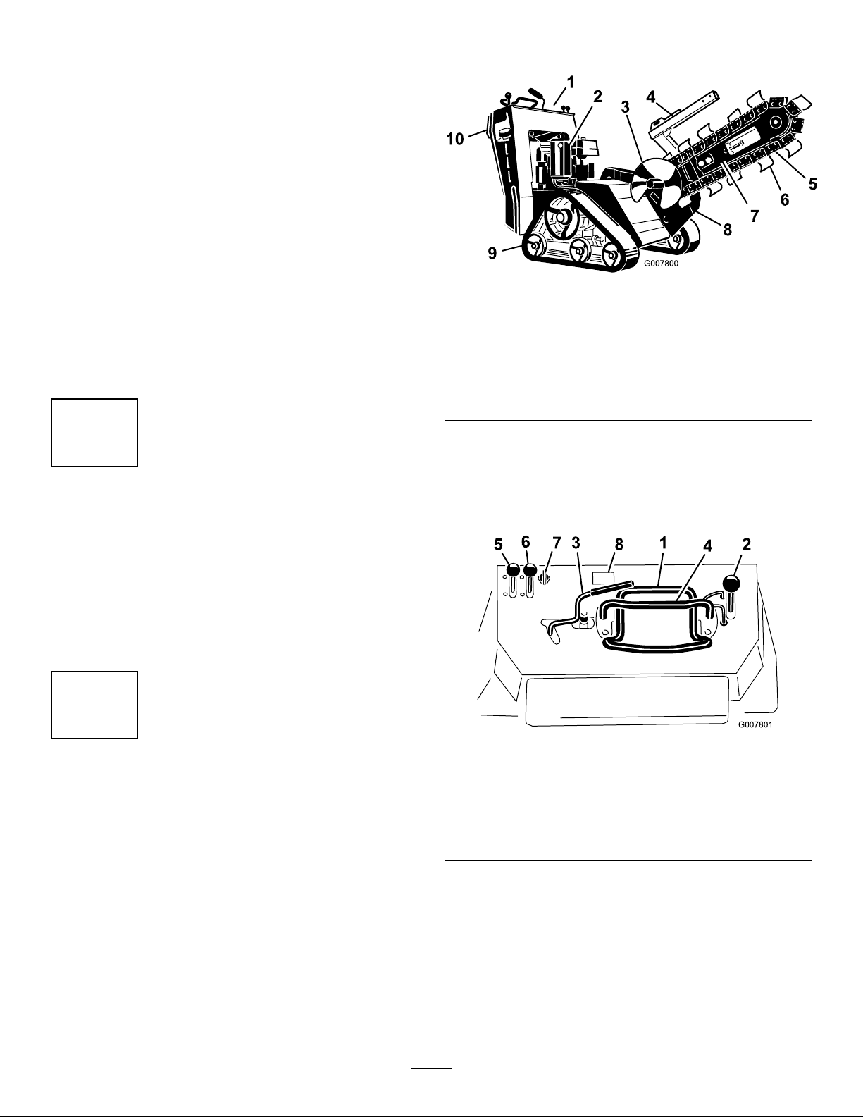
Figure4
1.Control
panel
2.Engine
3.Spoils
auger
4.Chain
guard
5.Chain
6.Digging
teeth
7.Boom10.Reverse
8.Trencher
head
9.Track
Controls
Becomefamiliarwithallthecontrols(Figure5)before
youstarttheengineandoperatethemachine.
safety
plate
3
ChargingtheBattery(Electric
StartModelsOnly)
NoPartsRequired
Procedure
Chargethebattery;refertoServicingtheBatteryin
Maintenanceformoreinformation.
Figure5
1.Tractioncontrol5.Throttlelever
2.Boomelevationlever
3.Trenchercontrollever7.Keyswitch
4.Referencebar8.Hourmeter(optional
6.Chokelever
KeySwitch,Model22970
Thekeyswitchhas2positions:offandrun.
Tostarttheengine,rotatethekeytotherunposition,
thenpulltherecoilhandleontheengine.
Tostoptheengine,rotatethekeytotheoffposition.
13
accessoryonmodel
22970)
Page 14
KeySwitch,ElectricStartModels
G008131
Thekeyswitchhasthreepositions:off,run,andstart.
Tostarttheengine,rotatethekeytothestartposition.
Releasethekeywhenenginestartsanditwillmove
automaticallytotherunposition.
Tostoptheengine,rotatethekeytotheoffposition.
ThrottleLever
•Tomoveforward,movethetractioncontrolforward
(Figure7).
Movethecontrolforwardtoincreasetheenginespeed
andrearwardtodecreasespeed.
ChokeLever
Beforestartingacoldengine,movethechokelever
forward.Aftertheenginestarts,regulatethechoketo
keeptheenginerunningsmoothly.Assoonaspossible,
movethechokeleverallthewayrearward.
Note:Awarmenginerequireslittleornochoking.
HourMeter
Whentheengineisoff,thehourmeterdisplaysthe
numberofhoursofoperationthathavebeenlogged
onthemachine.
Note:Thehourmeterisanoptionalaccessoryon
model22970.
ReferenceBar
Figure7
•Tomoverearward,movethetractioncontrol
rearward(Figure8).Whenreversing,lookbehind
forobstructionsandkeepyourhandsonthe
referencebar(Figure6).
Figure8
•Toturnright,rotatethetractioncontrolclockwise
(Figure9).
Whendrivingthemachine,usethereferencebarasa
handleandaleveragepointforcontrollingthetraction
controlandthetrenchercontrollever.Toensure
smooth,controlledoperation,donottakebothhands
offofthereferencebarwhileoperatingthemachine.
TractionControl
Figure6
1.Referencebar(doesnotmovetogiveyouareferencepoint
andaxedhandletoholdwhileoperatingthetractionunit)
2.Tractioncontrol(movestocontrolthemachine)
Figure9
•Toturnleft,rotatethetractioncontrol
counterclockwise(Figure10).
14
Page 15
G008132
Figure10
•Tostop,releasethetractioncontrol(Figure6).
Note:Thefartheryoumovethetractioncontrolin
anydirection,thefasterthemachinewillmoveinthat
direction.
BoomElevationLever
Tolowertheboom,slowlymovetheleverforward
(Figure11).
Toraisetheboom,slowlymovetheleverrearward
(Figure11).
Figure11
1.Lowertheboom2.Raisetheboom
Figure12
1.Boomelevationlever2.Boomelevationlock
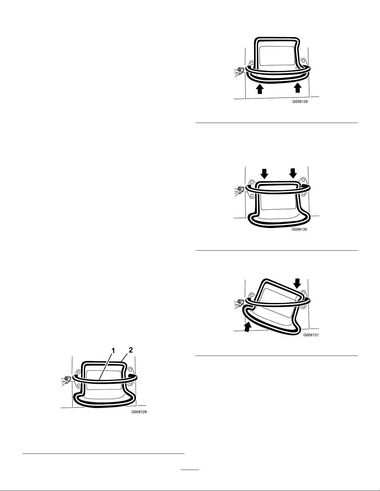
TrencherControlLever
Todigwiththetrencher,rotatetheleverrearwardand
pullitdowntothereferencebar(Figure13,number1).
Toreversethetrencherhead,rotatetheleverrearward,
thenmoveitleftintotheupperslot(Figure13,number
2).
Ifyoureleasethelever,itwillautomaticallyreturnto
theneutralposition(Figure13,number3),stoppingthe
chain.
BoomElevationLock
Theboomelevationlocksecurestheboomelevation
leversothatyoucannotpushitforward.Thishelpsto
ensurethatnoonewillaccidentallylowertheboom
duringmaintenance.Securetheboomwiththelock
anytimeyouneedtostopthemachinewiththeboom
raised.
Tosetthelock,liftuponitsoitclearstheholeinthe
controlpanelandswingittotherightinfrontofthe
boomelevationlever,pushingitdownintothelocked
position(Figure12).
Figure13
1.Forward3.Neutral
2.Reverse
15
Page 16
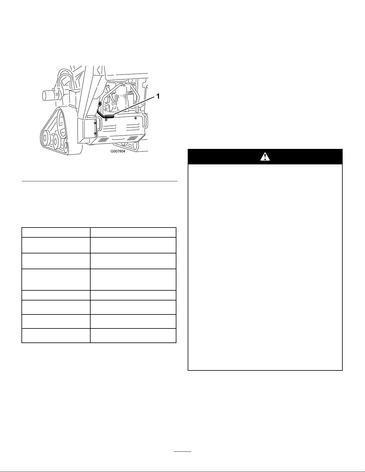
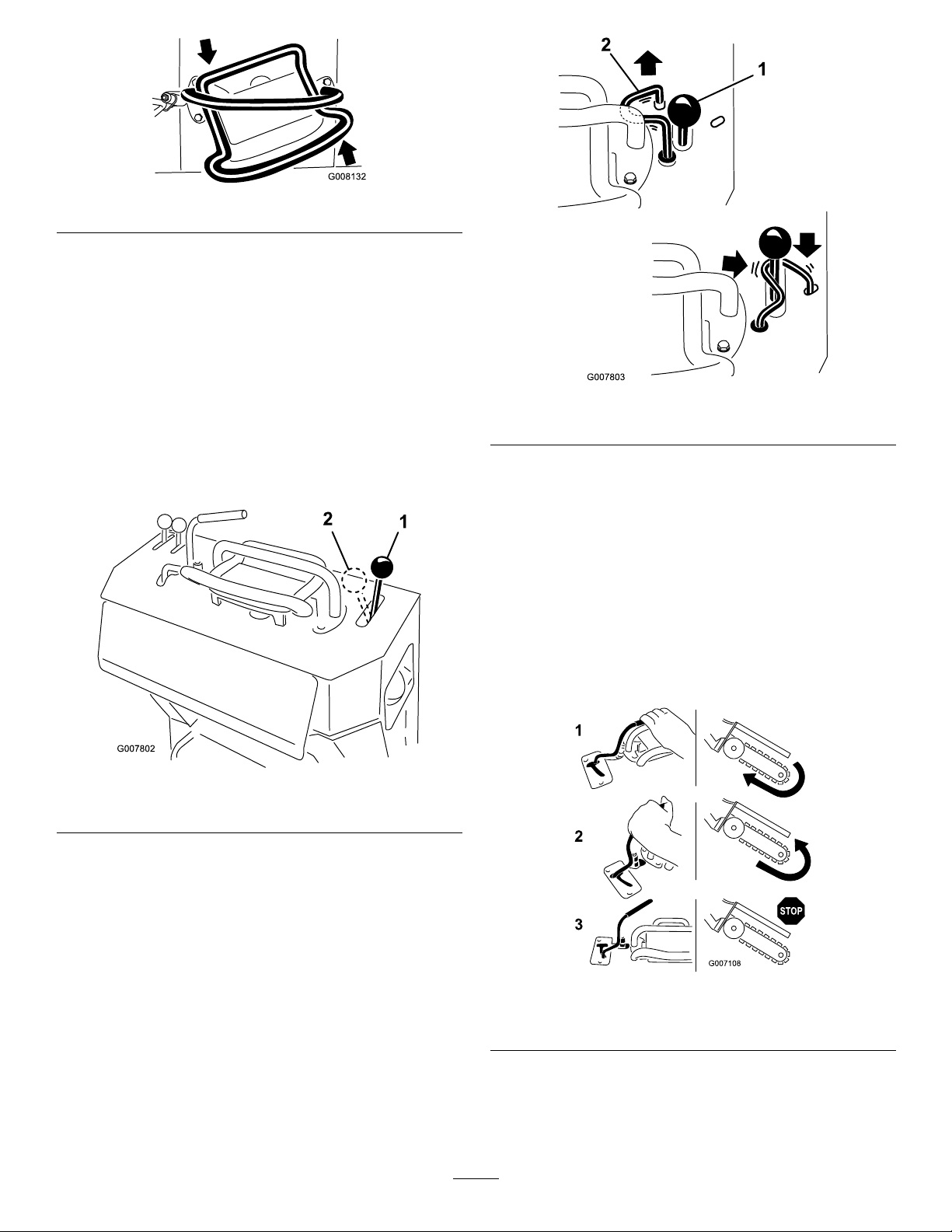
ParkingBrakeLever
G007804
1
•Tosettheparkingbrake,pullthebrakelever
rearwardandup(Figure14).
•Toreleasethebrake,pulltheleverrearwardandthen
down(Figure14).
Figure14
1.Parkingbrakelever(inthereleasedposition)
Specications
Note:Specicationsanddesignaresubjecttochange
withoutnotice.
Operation
Note:Determinetheleftandrightsidesofthe
machinefromthenormaloperatingposition.
Important:Beforeoperating,checkthefueland
oillevel,andremovedebrisfromthemachine.
Also,ensurethattheareaisclearofpeopleand
debris.Youshouldalsoknowandhavemarkedthe
locationsofallutilitylines.
AddingFuel
Useunleadedgasoline(87pumpoctaneminimum).
Leaded,regulargasolinemaybeusedifunleadedisnot
available.
Incertainconditions,gasolineisextremely
ammableandhighlyexplosive.Areor
explosionfromgasolinecanburnyouand
othersandcandamageproperty.
•Fillthefueltankoutdoors,inanopenarea,
whentheengineiscold.Wipeupany
gasolinethatspills.
Width
Length,with24inch(70
cm)boom
Length,with36inch(91.4
cm)boom
Length,with48inch(122
cm)boom(model22974
only)
Height
Weight(model22970)*1100lb(499Kg)
Weight(model22971)*1185lb(538Kg)
Weight(model22974)*1208lb(578Kg)
*A36inch(91.4cm)boomandchainwilladdabout60lbtothelistedweight.
33.8inches(86cm)
82.5inches(209.5cm)
92.6inches(235cm)
11 1.2inches(282.5cm)
46inches(117cm)
Attachments/Accessories
AselectionofToroapprovedattachmentsand
accessoriesareavailableforusewiththemachineto
enhanceandexpanditscapabilities.Contactyour
AuthorizedServiceDealerorDistributororgoto
www.Toro.comforalistofallapprovedattachments
andaccessories.
•Neverllthefueltankinsideanenclosed
trailer.
•Donotllthefueltankcompletelyfull.Add
gasolinetothefueltankuntilthelevelis1/4
to1/2inch(6to13mm)belowthebottomof
thellerneck.Thisemptyspaceinthetank
allowsgasolinetoexpand.
•Neversmokewhenhandlinggasoline,and
stayawayfromanopenameorwhere
gasolinefumesmaybeignitedbyaspark.
•Storegasolineinanapprovedcontainerand
keepitoutofthereachofchildren.Never
buymorethana30-daysupplyofgasoline.
•Donotoperatewithoutentireexhaust
systeminplaceandinproperworking
condition.
16
Page 17

Incertainconditionsduringfueling,static
G007806
1
electricitycanbereleasedcausingaspark
whichcanignitethegasolinevapors.Are
orexplosionfromgasolinecanburnyouand
othersandcandamageproperty.
•Alwaysplacegasolinecontainersonthe
groundawayfromyourvehiclebeforelling.
•Donotllgasolinecontainersinsidea
vehicleoronatruckortrailerbedbecause
interiorcarpetsorplastictruckbedliners
mayinsulatethecontainerandslowtheloss
ofanystaticcharge.
•Whenpractical,removegas-powered
equipmentfromthetruckortrailerand
refueltheequipmentwithitswheelsonthe
ground.
•Ifthisisnotpossible,thenrefuelsuch
equipmentonatruckortrailerfroma
portablecontainer,ratherthanfroma
gasolinedispensernozzle.
chanceofvarnishdepositsinthefuelsystem,usefuel
stabilizeratalltimes.
FillingtheFuelTank
1.Parkthemachineonalevelsurface,lowerthe
boom,andstoptheengine.
2.Removethekeyandallowtheenginetocool.
3.Cleanaroundthefueltankcapandremoveit
(Figure15).
Figure15
1.Fueltankcap
•Ifagasolinedispensernozzlemustbeused,
keepthenozzleincontactwiththerimof
thefueltankorcontaineropeningatall
timesuntilfuelingiscomplete.
Important:Donotusemethanol,gasoline
containingmethanol,orgasoholcontainingmore
than10%ethanolbecausethefuelsystemcouldbe
damaged.Donotmixoilwithgasoline.
UsingStabilizer/Conditioner
Useafuelstabilizer/conditionerinthemachineto
providethefollowingbenets:
•Keepsgasolinefreshduringstorageof90daysor
less.Forlongerstorageitisrecommendedthatthe
fueltankbedrained.
•Cleanstheenginewhileitruns
•Eliminatesgum-likevarnishbuildupinthefuel
system,whichcauseshardstarting
4.Addunleadedgasolinetothefueltank,untilthe
levelis1/4to1/2inchbelowthebottomofthe
llerneck.
Important:Thisspaceinthetankallows
gasolinetoexpand.Donotllthefueltank
completelyfull.
5.Installthefueltankcapsecurely.
6.Wipeupanygasolinethatmayhavespilled.
CheckingtheEngineOilLevel
ServiceInterval:Beforeeachuseordaily
1.Parkthemachineonalevelsurface,lowerthe
boom,andstoptheengine.
2.Removethekeyandallowtheenginetocool.
3.Cleanaroundtheoildipstick(Figure16).
Important:Donotusefueladditivescontaining
methanolorethanol.
Addthecorrectamountofgasstabilizer/conditioner
tothegas.
Note:Afuelstabilizer/conditionerismosteffective
whenmixedwithfreshgasoline.Tominimizethe
17
Page 18

Figure16
G007808
1
1.Oilllerhole
2.Oildipstick
3.Fullmark
4.Addmark
4.Removethedipstickandwipetheendclean
(Figure16).
5.Slidethedipstickfullyintothedipsticktubewithout
threadingitintothellerneck(Figure16).
6.Pullthedipstickoutandlookattheend.The
oilshouldbebetweentheAddandFullmarks
(Figure16).
7.IftheoilisbelowtheAddmark,add10w30engine
oiltothellerhole,checkingthelevelfrequently
withthedipstick,untiltheoillevelreachestheFull
mark.
8.Replacethedipstick.
CheckingtheHydraulicFluid
Level
Figure17
1.Hydraulicuidcheckbubble
4.Removethecoverplate;refertoRemovingthe
CoverPlate.
5.Cleantheareaaroundthellerneckofthehydraulic
tankandremovethecapandlterfromtheller
neckusingasocket(Figure18).
ServiceInterval:Every25hours
HydraulicTankCapacity:6USgallons(23l)
Use10W-30or15W -40detergent,dieselengineoil(API
serviceCH-4orhigher).
1.Parkthemachineonalevelsurfaceandlowerthe
boom.
2.Stoptheengine,removethekey ,andallowthe
enginetocool.
3.Lookintotheglassbubbleontherightsideofthe
machine.Ifyoucannotseehydraulicuidinthe
bubble,continuethisproceduretoadduid.
Figure18
1.Fillerneckcap
2.Hydraulicuidlter
6.Ifthelevelislow ,adduiduntilitisvisibleinthe
glassbubble.
7.Installthecapandlteronthellerneckandtorque
boltontopto110to140inch-lb(13to15.5N-m).
18
Page 19

StartingandStoppingthe
G007809
1
2
3
G007810
1
Engine
periodbetweenattempts.Failuretofollow
theseinstructionscanburnoutthestarter
motor.
StartingtheEngine
1.MovethethrottlelevermidwaybetweenSlowand
Fastpositions(Figure19).
Figure19
1.Throttlelever3.Key
2.Chokelever
2.MovethechokelevertotheOnposition(Figure19).
Note:Awarmorhotenginemaynotrequire
choking.
3.Starttheengineasfollowsforyourmodel:
•Formodel22970,turnthekeytotheOn
positionthenpulltherecoilhandletostartthe
engine(Figure20).
4.GraduallymovethechokelevertotheOffposition
(Figure19).Iftheenginestallsorhesitates,engage
thechokeagainuntiltheenginewarmsup.
5.Movethethrottlelevertothedesiredsetting
(Figure19).
Important:Iftheengineisrunathighspeeds
whenthehydraulicsystemiscold(i.e.,when
theambientairtemperatureisnearfreezingor
lower),hydraulicsystemdamagecouldoccur.
Whenstartingtheengineincoldconditions,
allowtheenginetoruninthemiddlethrottle
positionfor2to5minutesbeforemovingthe
throttletofast(rabbit).
Note:Iftheoutdoortemperatureisbelow
freezing,storethemachineinagaragetokeepit
warmerandaidinstarting.
StoppingtheEngine
1.MovethethrottlelevertotheSlowposition
(Figure19).
2.Lowertheboom(Figure21).
Figure20
1.Recoilhandle
•Foranelectricstartmodel,turnthekeytothe
Onposition(Figure19).Whentheenginestarts,
releasethekey .
Important:Donotengagethestarterfor
morethan10secondsatatime.Iftheengine
failstostart,allowa30secondcool-down
Figure21
3.Turnthekeyoff(Figure19).
Note:Iftheenginehasbeenworkinghardor
ishot,letitidleforaminutebeforeturningthe
ignitionkeyoff.Thishelpscooltheenginebefore
itisstopped.Inanemergency,theenginemaybe
stoppedimmediately .
4.Removethekey.
19
Page 20

StoppingtheMachine
G007816
1
Tostopthemachine,releasethetractioncontrol,move
thethrottlelevertoslow(turtle),lowertheboomto
theground,andstoptheengine.Settheparkingbrake
andremovethekey.
Achildoruntrainedbystandercouldattemptto
operatethemachineandbeinjured.
Removethekeyfromtheswitchwhenleaving
themachine,evenifjustforafewseconds.
MovingaNon-functioning
Machine
Important:Donottoworpullthemachine
withoutrstopeningthetowvalves,orthe
hydraulicsystemwillbedamaged.
1.Stoptheengine.
2.Removethebottomshield.
3.Usingawrench,turnthetowvalvesonthehydraulic
pumpstwicecounter-clockwise(Figure22).
2.Pullthetrenchercontrollevertothereferencebar
toengagethetrencher.
3.Slowlylowertheboomandchainintotheground.
Note:Toachievethemaximumdepth,youmay
needtolowertheboomasfarintothegroundas
itwillgowiththechainrunning.Then,stopthe
chainandloweritfully.Startthechainagainand
resumeoperation.
4.Oncethetrencherboomisinthegroundata45
to60degreeangle,slowlymovethetractionunit
rearwardtoextendthetrench.
Note:Ifyoumovetoofast,thetrencherwillstall.
Ifitstalls,raiseitslightly,slowlydriveforward,or
reversethechaindirectionmomentarily .
5.Whennished,raisetheboomoutofthetrench,
thenstopthetrencher.
SecuringtheMachinefor
Transport
Whentransportingthemachineonatrailer,alwaysuse
thefollowingprocedure:
Important:Donotoperateordrivethemachine
onroadways.
Figure22
1.Towvalves
4.Installthebottomshieldandtowthemachineas
required.
5.Whenthemachinehasbeenrepaired,closethetow
valvesbeforeoperatingit.
DiggingaTrench
1.Stoptheengine.
2.Lowertheboom.
3.Securethemachinetothetrailerwithchainsor
strapsusingthetie-down/liftloopsatthefrontand
rearofthemachine(Figure23andFigure24).Refer
toyourlocalordinancesfortrailerandtie-down
requirements.
Figure23
1.Fronttie-downloop
1.Starttheengine,raisetheboom,setthethrottle
levertotheFastposition,andmovethemachine
overtheareatobetrenched.
20
Page 21

1
G007818
Figure24
1.Reartie-downloops
LiftingtheMachine
Youcanliftthemachineusingthetie-down/liftloops
asliftpoints(Figure23andFigure24).
OperatingTips
•Cleantheareaoftrash,branchesandrocksbefore
trenchingtopreventequipmentdamage.
•Alwaysbegintrenchingwiththeslowestground
speedpossible.Increasespeedifconditionspermit.
Ifthechainspeedslowsdown,reducegroundspeed
tokeepthechainmovingatitsfastestrate.Donot
spinthetrackswhiletrenching.
•Alwaysusefullthrottle(maximumenginespeed)
whentrenching.
•Alwaystrenchbackwards(i.e.,inreverse).
•Trenchata45to60degreeangleforbestresults.
•Youwillbeabletodigatrenchfasterbycontrolling
thedepthwithperiodicadjustmentsoftheboom.
•Ifthetrencherbindsinthesoil,reversethechain
direction.Oncethechainisloose,changechain
directionsandcontinuetrenching.
•Ifyouneedthenishedtrenchtobecleanerthan
whatispossiblewiththetrencher,youcanpurchase
acrumberfromyourdealer.Thecrumbermounts
ontothetrencherheadandscrapesthetrenchclean
asyoudig.
•Toimprovethequalityoftrencheslessthan24inch
(60.9cm)deep,usea24inch(60.9cm)boom.
•Usethecorrectchainforthegroundconditions,as
listedinthefollowingtable:
SoilT ypeRecommendedChainType
SandySoilchain(re-congurewith
SandyLoam/Loam/Loamy
Clay
Wet,stickyclay
Hardsoils:dryclayand
compactedsoils
Rockysoil/gravel
extrateethforaddeddigging
speed;refertoyourAuthorized
ServiceDealer)
Soilchain
Soilchain
Combinationchain
Rockchain
21
Page 22

Maintenance
Note:Determinetheleftandrightsidesofthemachinefromthenormaloperatingposition.
RecommendedMaintenanceSchedule(s)
MaintenanceService
Interval
Aftertherst8hours
Aftertherst50hours
Beforeeachuseordaily
Every25hours
Every40hours
Every50hours
Every100hours
MaintenanceProcedure
•Changetheengineoil.
•Checkandadjustthetracktension.
•Checktheengineoillevel.
•Greasethemachine.(Greaseimmediatelyaftereverywashing.)
•Checktheengineoillevel.
•Checktheconditionofandcleanthetracks.
•Checktheconditionofthediggingteethandreplaceanythatarewornordamaged.
•Removedebrisfromthemachine.
•Checkforloosefasteners.
•Checkthehydraulicuidlevel.
•Cleanthefoamaircleanerelement.(Models22970and22971)
•Checkthebatteryelectrolytelevel.
•Checkthediggingchainforexcessivewearandpropertension.
•Greasethetrencherhousing.
•Checkthepaperaircleanerelement.(Models22970and22971)
•Changetheengineoil.
•Checkthesparkplugs.
•Checkandadjustthetracktension.
•Checkthehydrauliclinesforleaks,loosettings,kinkedlines,loosemounting
supports,wear,weather,andchemicaldeteriorationandrepairifnecessary.
•Replacethepaperaircleanerelement.(Models22970and22971)
Every200hours
Every250hours
Every400hours
Every1,500hours
Yearlyorbeforestorage
Important:Refertoyour
•Changetheoillter.
•Replacethefuellter .
•Replacethehydrauliclter.
•Replacetheprimaryairlterandcheckthecondtionofthesafetylter(Model22974)
•Checkandgreasetheroadwheels.
•Changethehydraulicuid.
•Replaceallmovinghydraulichoses.
•Checkandadjustthetracktension.
•Checkandadjustthechaintension.
•T ouchupchippedpaint
Engine Operator’ s Man ual
foradditionalmaintenanceprocedures.
Ifyouleavethekeyintheignitionswitch,someonecouldaccidentlystarttheengineandseriously
injureyouorotherbystanders.
Removethekeyfromtheignitionanddisconnectthewirefromthesparkplugbeforeyoudoany
maintenance.Setthewireasidesothatitdoesnotaccidentallycontactthesparkplug.
22
Page 23

Premaintenance
Procedures
Beforeopeninganyofthecovers,stoptheengine,
removethekey,andallowtheenginetocool.
Important:Thefastenersonthecoversofthis
machinearedesignedtoremainonthecoverafter
removal.Loosenallofthefastenersoneachcovera
fewturnssothatthecoverisloosebutstillattached,
thengobackandloosenthemuntilthecover
comesfree.Thiswillpreventyoufromaccidentally
strippingtheboltsfreeoftheretainers.
RemovingtheCoverPlate
1.Lowertheboom,stoptheengine,andremovethe
key.
Thereisabeltunderthecoverthatismoving
whenthemachineisrunningandcancatch
ngers,hands,loosehair,andclothing,causing
seriousinjury,amputation,ordeath.
Alwaysstoptheengineandwaitforallmoving
partstostopbeforeremovingthecover.
InstallingtheCoverPlate
1.Lowertheboom,stoptheengine,andremovethe
key.
2.Slidethecoverplateintoplaceandsecureitwiththe
threeboltsyouloosenedpreviously(Figure25).
RemovingtheBottomShield
1.Lowertheboom,stoptheengine,andremovethe
key.
2.Loosenthetwoboltssecuringthebottomshield
sequentiallyuntiltheshieldisfree(Figure26).
Figure26
1.Bottomshield3.Tabs
2.Bolts
3.Pulltheshieldbackandoutofthemachine.
2.Loosentheboltattherearofthecoverplate.
3.Loosenthethreeboltssecuringthecoverplatetothe
framesequentiallyuntilthecoverisfree(Figure25).
Figure25
1.Coverplate
4.Pullupontherearofthecoverplateuntilitclears
theengineandthenpullitoffofthemachine.
2.Bolts
InstallingtheBottomShield
1.Lowertheboom,stoptheengine,andremovethe
key.
2.Slidethebottomshieldintothemachinesothatit
restsonall4tabs(Figure26).
Note:Youmayneedtoliftuponthebottomshield
toensurethatitrestsonthefronttabs.
3.Securetheshieldwiththeboltsyouloosened
previously.
23
Page 24

Lubrication
GreasingtheMachine
ServiceInterval:Beforeeachuseordaily(Grease
immediatelyaftereverywashing.)
GreaseType:General-purposegrease.
1.Lowertheboomandstoptheengine.Removethe
key.
2.Cleanthegreasettingswitharag.
3.Connectagreaseguntoeachtting(Figure27
throughFigure30).
4.Pumpgreaseintothettingsuntilgreasebeginsto
oozeoutofthebearings(approximately3pumps).
5.Wipeupanyexcessgrease.
Figure29
Figure27
Figure28
Figure30
GreasingtheTrencher
Housing
ServiceInterval:Every40hours
GreaseType:General-purposegrease.
1.Lowertheboomandstoptheengine.Removethe
key.
2.Cleanthetrencherhousinggreasettingwitharag
andconnectagreaseguntoit(Figure31).
24
Page 25

Figure31
3.Pumpgreaseintothettinguntilgreasecomesout
ofthegreasevalvelocatednexttothetting.
EngineMaintenance
ServicingtheAirCleaner
(Models22970and22971)
ServiceInterval:Every25hours—Cleanthefoamair
cleanerelement.(Models22970and
22971)
Every50hours—Checkthepaperair
cleanerelement.(Models22970and
22971)
Every200hours/Yearly(whichever
comesrst)—Replacethepaperair
cleanerelement.(Models22970and
22971)
4.Wipeupanyexcessgrease.
Inspectthefoamandpaperelementsandreplacethem
iftheyaredamagedorexcessivelydirty.
Note:Servicetheaircleanermorefrequently(every
fewoperatinghours)iftheoperatingconditionsare
extremelydustyorsandy .
Important:Donotoilthefoamorpaperelement.
RemovingtheFoamandPaper
Elements
1.Lowertheboomandsettheparkingbrake.
2.Stoptheengine,removethekey,andwaitforall
movingpartstostopbeforeleavingtheoperating
position.
3.Cleanaroundtheaircleanertopreventdirt
fromgettingintotheengineandcausingdamage
(Figure32).
4.Unscrewthecoverknobandremovetheaircleaner
cover(Figure32).
5.Removethe2wingnutsandremovetheaircleaner
assembly(Figure32).
6.Carefullypullthefoamelementoffthepaper
element(Figure32).
25
Page 26

2.Placetheaircleanerassemblyontotheaircleaner
G011475
1
2
3
4
5
baseandsecureitwiththe2wingnuts(Figure32).
3.Placetheaircleanercoverintopositionandtighten
thecoverknob(Figure32).
ServicingtheAirCleaner
(Model22974)
ServiceInterval:Every250hours
ServicingtheAirCleanerCoverand
Body
1.Stoptheengineandremovethekey.
2.Checktheaircleanerbodyfordamagewhichcould
causeanairleak.Checkthewholeintakesystem
forleaks,damage,orloosehoseclamps.Replaceor
repairanddamagedcomponents.
3.Releasethelatchesontheaircleanerandpulltheair
cleanercoveroffoftheaircleanerbody(Figure33).
Figure32
1.Engine4.Foamelement
2.Cover
3.Wingnut
5.Paperelement
6.Coverknob
CleaningtheFoamAirCleanerElement
1.Washthefoamelementinliquidsoapandwarm
water.Whentheelementisclean,rinseitthoroughly.
2.Drytheelementbysqueezingitinacleancloth.
Important:Replacethefoamelementifitis
tornorworn.
ServicingthePaperAirCleaner
Element
Donotcleanthepaperlter.Replaceitafter200
operatinghours(Figure32).Inspecttheelementfor
tears,anoilylm,ordamagetotherubberseal,and
replaceitifitisdamaged.
InstallingtheFoamandPaperElements
Important:Topreventenginedamage,always
operatetheenginewiththecompletefoamand
paperaircleanerassemblyinstalled.
1.Carefullyslidethefoamelementontothepaperair
cleanerelement(Figure32).
Important:Donotremovetheairltersyet.
Figure33
1.Airlterbody
2.Safetylter
3.Primarylter
4.Aircleanercover
5.Dustcap
4.Squeezethedustcapsidestoopenitandknockthe
dustout.
5.Cleantheinsideoftheaircleanercoverwith
compressedair.
ReplacingtheFilters
1.Gentlyslidetheprimarylteroutoftheaircleaner
body(Figure33).Avoidknockingthelterintothe
sideofthebody.
26
Page 27

Important:Donotattempttocleantheprimary
lter.
2.Checktheconditionofthesafetylterwithout
removingit.Ifitisdirtyordamaged,replaceit.
Important:Neverattempttocleanthesafety
lter.
3.Inspectthenewlter(s)fordamagebylookinginto
thelterwhileshiningabrightlightontheoutside
ofthelter.Holesinthelterwillappearasbright
spots.Inspecttheelementfortears,anoilylm,or
damagetotherubberseal.Ifthelterisdamaged
donotuseit.
4.Ifyouarereplacingthesafetylter,carefullyslide
thenewlterintothelterbody(Figure33).
Figure34
Important:T opreventenginedamage,always
operatetheenginewithbothairltersandcover
installed.
5.Carefullyslidetheprimarylteroverthesafetylter
(Figure33).Ensurethatitisfullyseatedbypushing
ontheouterrimofthelterwhileinstallingit.
Important:Donotpressonthesoftinsidearea
ofthelter.
6.Installtheaircleanercoverwiththedustcaporiented
asshowninFigure33andsecurethelatches.
ServicingtheEngineOil
ServiceInterval:Aftertherst8hours—Changethe
engineoil.
Beforeeachuseordaily—Checkthe
engineoillevel.
Every100hours—Changetheengine
oil.
Every200hours—Changetheoil
lter.
Note:Changetheoilmorefrequentlywhenthe
operatingconditionsareextremelydustyorsandy.
OilType:Detergentoil(APIserviceSF,SG,SH,orSJ)
CheckingtheEngineOilLevel
1.Parkthemachineonalevelsurface.
2.Lowertheboomandsettheparkingbrake.
3.Stoptheengine,removethekey,andwaitforall
movingpartstostopbeforeleavingtheoperating
position.
4.Cleanaroundtheoildipstick(Figure35)sothatdirt
cannotfallintothellerholeanddamagetheengine.
Figure35
1.Oildipstick
5.Unscrewtheoildipstickandwipetheendclean
(Figure35).
6.Slidetheoildipstickfullyintothellertube,butdo
notthreadontotube(Figure35).
2.Fillertube
CrankcaseCapacity:58ounces(1.7liter)withthelter
removed;51ounces(1.5liter)withoutthelterremoved
Viscosity:Refertothetable(Figure34).
7.Pullthedipstickoutandlookattheend.Iftheoil
levelislow ,slowlypouronlyenoughoilintotheller
tubetoraisetheleveltotheFullmark.
Important:Donotoverllthecrankcasewith
oilandruntheengine;enginedamagecan
result.
27
Page 28

ChangingtheOil
1.Starttheengineandletitrunveminutes.This
warmstheoilsoitdrainsbetter.
2.Parkthemachinesothatthedrainsideisslightly
lowerthantheoppositesidetoensurethattheoil
drainscompletely .
3.Lowertheboomandsettheparkingbrake.
4.Stoptheengine,removethekey,andwaitforall
movingpartstostopbeforeleavingtheoperating
position.
5.Placeapanbelowthedrainhose.Rotatetheoildrain
valvetoallowoiltodrain(Figure36).
Figure37
1.Oillter
2.Adapter
3.Applyathincoatofnewoiltotherubbergasketon
thereplacementlter(Figure37).
4.Installthereplacementoilltertothelteradapter,
turntheoillterclockwiseuntiltherubbergasket
contactsthelteradapter,thentightenthelteran
additional3/4turn(Figure37).
5.Fillthecrankcasewiththepropertypeofnewoil;
refertoServicingtheEngineOil.
Figure36
Onmodel22974,theoildrainisontheoppositesideof
themachine.
1.Oildrainvalve2.Oildrainhose
6.Whenoilhasdrainedcompletely,closethedrain
valve.
7.Disposeoftheusedoilatarecyclingcenter
8.Slowlypourapproximately80%ofthespeciedoil
intothellertube(Figure35).
9.Checktheoillevel;refertoCheckingtheEngineOil
Level.
10.SlowlyaddtheadditionaloiltobringittotheFull
mark.
ChangingtheOilFilter
6.Runtheengineforabout3minutes,stoptheengine,
andcheckforoilleaksaroundtheoillteranddrain
valve.
7.Checktheengineoillevelandaddoilifneeded.
8.Wipeupanyspilledoil.
ServicingtheSparkPlug
ServiceInterval:Every100hours—Checkthespark
plugs.
Ensurethattheairgapbetweenthecenterandside
electrodesiscorrectbeforeinstallingthesparkplug.
Useasparkplugwrenchforremovingandinstallingthe
sparkplugandagappingtool/feelergaugetocheckand
adjusttheairgap.Installanewsparkplugifnecessary.
Type:
•Models22970and22971—Champion®RCJ8Yor
equivalent;AirGap:0.030inch(0.75mm)
•Model22974—NGKBPR4Esorequivalent;Air
Gap:0.030inch(0.75mm)
1.Draintheoilfromtheengine;refertoChangingthe
EngineOil.
2.Removetheoldlter(Figure37).
RemovingtheSparkPlug
1.Lowertheboomandsettheparkingbrake.
2.Stoptheengine,removethekey,andwaitforall
movingpartstostopbeforeleavingtheoperating
position.
3.Disconnectthewirefromthesparkplug(Figure38).
28
Page 29

1
Figure38
1.Spark-plugwire/sparkplug
4.Cleanaroundthesparkplugtopreventdirtfrom
fallingintotheengineandpotentiallycausing
damage.
Note:Theheatshieldmayinterfereontheright
side;removeitifnecessaryandreplaceitwhen
nished.
Important:Alwaysreplacethesparkplugwhen
ithaswornelectrodes,anoilylmonit,orhas
cracksintheporcelain.
3.Checkthegapbetweenthecenterandsideelectrodes
(Figure39).Bendthesideelectrode(Figure39)if
thegapisnotcorrect.
InstallingtheSparkPlug
1.Installthesparkplugandthemetalwasher.Ensure
thattheairgapissetcorrectly.
2.Tightenthesparkplugto16ft-lb(22N-m).
3.Connectthewiretothesparkplug(Figure39).
5.Removethesparkplugandthemetalwasher.
CheckingtheSparkPlug
1.Lookatthecenterofthesparkplug(Figure39).
Ifyouseelightbrownorgrayontheinsulator,the
engineisoperatingproperly.Ablackcoatingonthe
insulatorusuallymeansthattheaircleanerisdirty.
2.Ifneeded,cleanthesparkplugwithawirebrushto
removecarbondeposits.
Figure39
1.Centerelectrodeinsulator3.Airgap(nottoscale)
2.Sideelectrode
29
Page 30

FuelSystem
Maintenance
DrainingtheFuelTank
Note:Nowisthebesttimetoinstallanewfuellter
becausethefueltankisempty .RefertoReplacing
theFuelFilter.
7.Installthefuellineontothefuelshut-offvalve.Slide
thehoseclampclosetothevalvetosecurethefuel
line.
8.Wipeupanyspilledfuel.
Incertainconditions,gasolineisextremely
ammableandhighlyexplosive.Areor
explosionfromgasolinecanburnyouand
othersandcandamageproperty.
•Draingasolinefromthefueltankwhenthe
engineiscold.Dothisoutdoorsinanopen
area.Wipeupanygasolinethatspills.
•Neversmokewhendraininggasoline,and
stayawayfromanopenameorwherea
sparkmayignitethegasolinefumes.
1.Parkthemachineonalevelsurface,toensurethat
thefueltankdrainscompletely.
2.Lowertheboomandsettheparkingbrake.
3.Stoptheengine,removethekey,andwaitforall
movingpartstostopbeforeleavingtheoperating
position.
4.Turnthefuelshut-offvalvetotheclosedposition
(Figure40).
ReplacingtheFuelFilter
ServiceInterval:Every200hours
Neverinstalladirtylterifitisremovedfromthefuel
line.
Note:Notehowthefuellterisinstalledinorderto
installthenewltercorrectly.
Note:Wipeupanyspilledfuel.
1.Lowertheboomandsettheparkingbrake.
2.Stoptheengine,removethekey,andwaitforall
movingpartstostopbeforeleavingtheoperating
position.
3.Turnthefuelshut-offvalvetotheclosedposition
(Figure40).
4.Squeezetheendsofthehoseclampstogetherand
slidethemawayfromthelter(Figure41).
Figure40
1.Fuelshut-offvalve
5.Squeezetheendsofthehoseclampontheengine
sideoftheshut-offvalvetogetherandslideitupthe
fuellineawayfromvalve(Figure40).
6.Pullthefuellineoffthevalve(Figure40).Openthe
fuelshut-offvalveandallowthegasolinetodrain
intoagascanordrainpan.
Figure41
1.Hoseclamp3.Filter
2.Fuelline
5.Removethelterfromthefuellines.
6.Installanewlterandmovethehoseclampsclose
tothelter.
7.Turnthefuelshut-offvalvetotheopenposition
(Figure40).
8.Checkforfuelleaksandrepairifneeded.
9.Wipeupanyspilledfuel.
30
Page 31

ElectricalSystem
Maintenance
ServicingtheBattery(Models
22971and22974)
ServiceInterval:Every25hours—Checkthebattery
electrolytelevel.
Alwayskeepthebatterycleanandfullycharged.Use
apapertoweltocleanthebatterycase.Ifthebattery
terminalsarecorroded,cleanthemwithasolutionof
fourpartswaterandonepartbakingsoda.Applyalight
coatingofgreasetothebatteryterminalstoprevent
corrosion.
Voltage:12Vwith280coldcrankingAmps@0degrees
F(-18degreesC).
Warning
CALIFORNIA
Proposition65Warning
Batteryposts,terminals,andrelated
accessoriescontainleadandleadcompounds,
chemicalsknowntotheStateofCalifornia
tocausecancerandreproductiveharm.
Washhandsafterhandling.
RemovingtheBattery
Batteryterminalsormetaltoolscouldshort
againstmetalmachinecomponentscausing
sparks.Sparkscancausethebatterygassesto
explode,resultinginpersonalinjury.
•Whenremovingorinstallingthebattery,do
notallowthebatteryterminalstotouchany
metalpartsofthemachine.
•Donotallowmetaltoolstoshortbetween
thebatteryterminalsandmetalpartsofthe
machine.
Incorrectbatterycableroutingcoulddamage
themachineandcablescausingsparks.Sparks
cancausethebatterygassestoexplode,
resultinginpersonalinjury.
•AlwaysDisconnectthenegative(black)
batterycablebeforedisconnectingthe
positive(red)cable.
•AlwaysReconnectthepositive(red)battery
cablebeforereconnectingthenegative
(black)cable.
Batteryelectrolytecontainssulfuricacidwhich
isadeadlypoisonandcausessevereburns.
Donotdrinkelectrolyteandavoidcontactwith
skin,eyesorclothing.Wearsafetyglassesto
shieldyoureyesandrubberglovestoprotect
yourhands.
1.Lowertheboomandsettheparkingbrake.
2.Stoptheengine,removethekey,andwaitforall
movingpartstostopbeforeleavingtheoperating
position.
3.Lifttheblackrubbercoveronthenegativecable.
Disconnectthenegativebatterycablefromthe
negative(-)batteryterminal(Figure42).
31
Page 32

Figure42
1.Negativecable7.Positivecable
2.Nut(1/4inch)
3.Nut(5/16inch)
4.Bolt10.J-bolt
5.Rubbercover(red)
6.Rubbercover(black)
8.Batteryholddownplate
9.Washer
11.Battery
CheckingtheBatteryElectrolyteLevel
Batteryelectrolytecontainssulfuricacidwhich
isadeadlypoisonandcausessevereburns.
•Donotdrinkelectrolyteandavoidcontact
withskin,eyesorclothing.Wearsafety
glassestoshieldyoureyesandrubbergloves
toprotectyourhands.
•Fillthebatterywherecleanwaterisalways
availableforushingtheskin.
1.Lookatthesideofthebattery.Theelectrolytemust
beuptotheupperline(Figure43).Donotallowthe
electrolytetofallbelowtheLowerline(Figure43).
Figure43
1.Ventcaps3.Lowerline
2.Upperline
4.Slidetheredterminalbootoffthepositive(red)
batteryterminal.Thenremovethepositive(red)
batterycable(Figure42).
5.Removetheholddownplate,j-bolts,andlocknuts
securingthebattery(Figure42)andremovethe
battery.
InstallingtheBattery
1.Placethebatteryontothemachine(Figure42).
2.Securethebatterywiththeholddownplate,j-bolts,
andlocknuts.
3.First,installthepositive(red)batterycableto
positive(+)batteryterminalwithanut,washerand
bolt(Figure42).Slidetherubbercoveroverthepost.
4.Theninstallthenegativebatterycableandground
wiretothenegative(-)batteryterminalwithanut,
washerandbolt(Figure42).Slidetherubbercover
overthepost.
2.Iftheelectrolyteislow ,addtherequiredamountof
distilledwater;refertoAddingWatertotheBattery.
AddingWatertotheBattery
Thebesttimetoadddistilledwatertothebatteryisjust
beforeyouoperatethemachine.Thisletsthewatermix
thoroughlywiththeelectrolytesolution.
1.Removethebatteryfromthemachine;referto
RemovingtheBattery.
Important:Neverllthebatterywithdistilled
waterwhilethebatteryisinstalledinthe
machine.Electrolytecouldbespilledonother
partsandcausecorrosion.
2.Cleanthetopofthebatterywithapapertowel.
3.Removetheventcapsfromthebattery(Figure43).
4.Slowlypourdistilledwaterintoeachbatterycell
untiltheelectrolytelevelisuptotheUpperline
(Figure43)onthebatterycase.
Important:Donotoverllthebatterybecause
electrolyte(sulfuricacid)cancausesevere
corrosionanddamagetothechassis.
32
Page 33

5.Waitvetotenminutesafterllingthebatterycells.
Adddistilledwater,ifnecessary,untiltheelectrolyte
levelisuptotheUpperline(Figure43)onthe
batterycase.
6.Installthebatteryventcaps.
ChargingtheBattery
Chargingthebatteryproducesgassesthatcan
explode.
Neversmokenearthebatteryandkeepsparks
andamesawayfrombattery.
Important:Alwayskeepthebatteryfullycharged
(1.265specicgravity).Thisisespeciallyimportant
topreventbatterydamagewhenthetemperatureis
below32°F(0°C).
1.Removethebatteryfromthechassis;referto
RemovingtheBattery.
2.Checktheelectrolytelevel;refertoCheckingthe
ElectrolyteLevel.
ReplacingtheFuses(Models
22971and22974)
Thereare4fusesintheelectricalsystem.Theyareunder
thecontrolpanelontheleftside(Figure45).
StartCircuit
ChargeCircuit
CoolerfanCircuit
Headlight(optional)
Figure45
1.Fuseblock
30amp
25amp
15amp
15amp
3.Makesurethellercapsareinstalledinbattery.
Connecta3to4ampbatterychargertothebattery
posts.Chargethebatteryatarateof3to4amperes
for4to8hours(12volts).Donotoverchargethe
battery.
4.Whenthebatteryisfullycharged,unplugthecharger
fromtheelectricaloutlet,thendisconnectthe
chargerleadsfromthebatteryposts(Figure44).
5.Installthebatteryontothemachineandconnectthe
batterycables,refertoInstallingtheBattery.
Note:Donotrunthemachinewiththebattery
disconnected,electricaldamagemayoccur.
1.PositiveBatteryPost
2.NegativeBatteryPost
Figure44
3.Red(+)ChargerLead
4.Black(-)ChargerLead
33
Page 34

DriveSystem
Maintenance
ServicingtheTracks
CleaningtheTracks
ServiceInterval:Beforeeachuseordaily
Checkthetracksforexcessivewearandcleanthem
periodically.Ifthetracksareworn,replacethem.
1.Lowertheboomandsettheparkingbrake.
2.Stoptheengine,removethekey,andwaitforall
movingpartstostopbeforeleavingtheoperating
position.
3.Usingawaterhoseorpressurewasher,removedirt
fromeachtracksystem.
Important:Ensurethatyouusehigh-pressure
watertowashonlythetrackarea.Donotuse
ahigh-pressurewashertocleantherestofthe
machine.High-pressurewashingcandamagethe
electricalsystemandhydraulicvalvesordeplete
grease.
Important:Ensurethatyoufullycleantheroad
wheelsandthedrivesprocket(Figure46).
thedrivesprocket.Thetrackshouldexnomorethan
1/4to3/8inch(0.6to1cm).Ifitdoes,adjustthetrack
tensionusingthefollowingprocedure:
Figure47
1.Stopthemachineinonalevelsurfaceandsetthe
parkingbrake.
2.Stoptheengine,lowertheboom,removethekey,
andwaitforallmovingpartstostopbeforeleaving
theoperatingposition.
3.Loosenthejamnutonthetracktensioningboltand
theclampboltsonthetensionarm(Figure48).
Figure46
1.Roadwheels3.Track
2.Drivesprocket
CheckingandAdjustingtheTrack
Tension
ServiceInterval:Aftertherst50hours
Every100hours
Tocheckthetensionofeachtrack,place45lb(20.4kg)
onthetrackmidwaybetweenthefrontroadwheeland
Figure48
1.Tensioningbolt
2.Jamnut
4.Torquethetensioningboltto24to30ft-lb(32.5to
40N-m)totightenthetrack(Figure48).
5.Ensurethatthetrackdeectslessthan1/4to3/8
inch(0.6to1cm)when45lb(20.6kg)offorceis
appliedtothetrackspan.Adjustthetorqueonthe
tensioningboltasneeded.
6.Tightenthejamnut.
7.Tightentheclampboltsandtorqueto75ft-lb(102
N-m).
34
3.Clampbolts
Page 35

ReplacingtheTracks
Whenthetracksarebadlyworn,replacethem.
1.Lowertheboomandsettheparkingbrake.
2.Stoptheengine,removethekey,andwaitforall
movingpartstostopbeforeleavingtheoperating
position.
3.Lift/supportthesideoftheunittobeworkedon
sothatthetrackis3to4inches(7.6to10cm)off
oftheground.
4.Backoutthetensioningboltandjamnut(Figure48).
5.Loosentheclampbolts(Figure48).
6.Pushthefrontroadwheelrearwardasfarasitwill
go(Figure49).
Figure50
1.Snapring4.Gasket
2.Cap
3.Bolt
5.Wheelwithbearings
8.Whenthetrackisoffoftheroadwheel,removeit
fromthemachine(Figure49).
9.Beginningatthedrivesprocket,coilthenewtrack
aroundthesprocket,ensuringthatthelugson
thetracktbetweenthespacersonthesprocket
(Figure49).
Figure49
7.Beginremovingthetrackatthetopofthefrontroad
wheel,peelingitoffofthewheelwhilerotatingthe
trackforwards.
Note:Youmayneedtoremovethefront,outside
roadwheel.T oremovethiswheel,removethesnap
ringandcapfromthecenteroftheroadwheel
(Figure50).Nextremovetheboltandgasketfrom
thecenterofthewheelandpullthewheeloffofthe
machine.
10.Pushthetrackunderandbetweentherearandcenter
roadwheels(Figure49).
11.Startingatthebottomofthefrontroadwheel,install
thetrackaroundthewheelbyrotatingthetrack
rearwardwhilepushingthelugsintothewheel.
12.Ifyouremovedthefront,outsideroadwheel,install
itatthistimeusingtheboltandgasketremoved
previously.Torquetheboltto75ft-lb(102N-m)
andthenclean,grease,andinstallthecapandsnap
ringasinstructionintheCheckingandGreasingthe
RoadWheelssection.
13.Installthetensioningboltandjamnut.
14.Torquethetensioningboltto24to30ft-lb(32.5to
40N-m)totightenthetrack.
15.Ensurethatthetrackdeectslessthan1/4to3/8
inch(0.6to1cm)when45lb(20.6kg)offorceis
appliedtothetrackspan.Adjustthetorqueonthe
tensioningboltasneeded.
16.Tightenthejamnut.
17.Tightentheclampboltsandtorqueto75ft-lb(102
N-m).
18.Lowerthemachinetotheground.
19.Repeatsteps3through18toreplacetheothertrack.
35
Page 36

CheckingandGreasingtheRoad
Wheels
BeltMaintenance
ServiceInterval:Every250hours
1.Removethetracks;refertoReplacingtheTracks.
2.Removethesnapringandcapfromaroadwheel
(Figure51).
Figure51
1.Roadwheel
2.Roadwheelcap
3.Snapring
3.Checkthegreaseunderthecapandaroundthe
gasket(Figure51).Ifitisdirty,gritty,ordepleted,
cleanoutallofthegrease,replacethegasket,and
addnewgrease.
ReplacingthePumpDriveBelt
Ifthepumpdrivebeltbeginstosquealoriscracked,
worn,orfrayed,replaceit.ContactyouAuthorized
ServiceDealerforareplacementbelt.
1.Raisetheboomandsettheparkingbrake.
2.Stoptheengine,removethekey,andwaitforall
movingpartstostopbeforeleavingtheoperating
position.
3.Raisethebackofthemachineandsupportitonjack
stands.
4.Removethebottomshield;refertoRemovingthe
BottomShield.
5.Loosenthetwopumpbolts(Figure52).
4.Ensurethattheroadwheelturnssmoothlyonthe
bearing.Ifitisfrozen,contactyourAuthorized
ServiceDealertoreplacetheroadwheel.
5.Placethegreasedroadwheelcapoverthebolthead
(Figure51).
6.Securetheroadwheelcapwiththesnapring
(Figure51).
7.Repeatsteps2through6forall12roadwheels.
8.Installthetracks;refertoReplacingtheTracks.
Figure52
1.Pump3.Belt
2.Pumpbolts4.Idlerpulleyspring
6.Twistthepumpcounterclockwiseandallowitto
dropdownawayfromthepulley(Figure52).Ensure
thatthespidercouplerdropsdownwiththepump.
7.Usingaspringpuller(contactyourAuthorized
ServiceDealer)orstiffmetalhook,pulltheendof
theidlerpulleysprintoffofthespringbolttorelease
tensiononthebelt(Figure52).
8.Removethebelt.
9.Routeanewbeltaroundthepulleys.
10.Installtheidlerpulleyspringonthebolt.
11.Ensurethatthespidercouplerisinplaceonthe
pumpandtheninsertitintothepulley,twistingit
clockwisetoseatitonthepumpbolts.
12.Torquethepumpboltsto50ft-lb(68N-m).
13.Installthebottomshield.
36
Page 37

ControlsSystem
Maintenance
Thefactoryadjuststhecontrolsbeforeshippingthe
machine.However,aftermanyhoursofuse,youmay
needtoadjustthetractioncontrolalignment,theneutral
positionofthetractioncontrol,andthetrackingofthe
tractioncontrolinthefullforwardposition.
Important:T oadjustthecontrolsproperly,
completeeachprocedureintheorderlisted.
AdjustingtheTractionControl
Alignment
Ifthetractioncontrolbardoesnotrestushand
squarewiththereferencebarwheninthefullbackward
position,immediatelycompletethefollowingprocedure:
1.Parkthemachineonaatsurfaceandlowerthe
boom.
2.Stoptheengineandremovethekey.
Figure54
1.Tractioncontrol
5.Adjustthetractioncontrolsothatitrestsush
againstthereferencebarwhenitispulledstraight
back(Figure54andFigure55).
2.Stem,boltandnut
3.Pullstraightbackonthetractioncontrolsothefront
ofthecontrolcontactsthereferencebar(Figure53).
Figure53
1.Frontofthecontrol,outof
alignment
4.Ifthefrontofthetractioncontroldoesnotrest
squareandushwiththereferencebar,loosenthe
angenutandboltinthestemofthetractioncontrol
(Figure54).
2.Referencebar
Figure55
6.Tightentheangenutandboltinthetraction
controlstem.
7.Starttheengine.
8.Drivethemachineinreversewiththetraction
controltighttothereferencebar.Ifthemachine
doesnotbackupstraight,completethefollowing
procedure:
A.Stoptheengine
B.Lift/supportthemachinesothatbothtracksare
offofthegroundandarefreetorun.
C.Loosentheangenutandboltinthestemofthe
tractioncontrol(Figure54).
D.Loosenthejamnutsonthetractionrods,under
thecontrolpanel(Figure56).
37
Page 38

G011476
1
1
2
2
Figure56
1.Tractionrod2.Jamnut
E.Startthemachineandsetthethrottletoabout
1/3openposition.
AdjustingtheTractionControl
NeutralPosition
Ifthemachinecreepsforwardorbackwardwhenthe
tractioncontrolisinneutralandtheunitiswarm,the
return-to-neutralmechanismonthepumpsmayneed
tobeadjusted;contactyouAuthorizedServiceDealer
forrepairs.
AdjustingtheTrackingofthe
TractionControl,FullForward
Position
Ifthemachinedoesnotdrivestraightwhenyouhold
thetractioncontrolforwardagainstthereferencebar,
completethefollowingprocedure:
1.Drivethemachinewiththetractioncontrolagainst
thereferencebar,notingwhichdirectionthe
machineveers.
2.Releasethetractioncontrol.
Whenthemachineisrunning,youcouldbe
caughtandinjuredinmovingpartsorburned
onhotsurfaces.
Stayawayfrompinchpoints,movingparts,
andhotsurfaceswhenadjustingtherunning
machine.
F.Haveahelperholdthetractioncontroltightto
thereferencebarinreverse.
G.Adjustthelengthofthetractionrodsuntilboth
tracksarerunningatthesamespeed.
Note:Youcanalsoadjustthemaximumreverse
speedofthetracksatthistime.
H.Tightenthejamnuts.
I.Adjustthetractioncontrolsothatitrestsush
againstthereferencebarwhenitispulledstraight
back(Figure54andFigure55).
J.Tightentheangenutandboltinthetraction
controlstem.
K.Stoptheengineandlowerthemachinetothe
ground.
L.Drivethemachineinfullreverse,checkingto
seeiftheunittracksstraight.Ifitdoesnot,
notethedirectionthemachineveers.Repeatthe
adjustmentpreviouslydescribedsothatittracks
straightinreverse.
3.Ifthemachineveerstotheleft,loosentherightjam
nutandadjustthetrackingsetscrewonthefrontof
thetractioncontrol(Figure57).
4.Ifthemachineveerstotheright,loosentheleftjam
nutandadjustthetrackingsetscrewonthefrontof
thetractioncontrol(Figure57).
Figure57
1.Setscrew3.Stop
2.Jamnut
5.Repeatsteps1through4untilthemachinedrives
straightinthefullforwardposition.
Important:Ensurethetrackingsetscrews
touchthestopsinthefullforwardpositionto
avoidoverstrokingthehydraulicpumps.
38
Page 39

HydraulicSystem
Maintenance
ReplacingtheHydraulicFilter
ServiceInterval:Every200hours
1.Positionmachineonalevelsurface.
2.Lowertheboomandsettheparkingbrake.
3.Stoptheengine,removethekey,andwaitforall
movingpartstostopbeforeleavingtheoperating
position.
4.Removethetopcover.
5.Removeanddiscardtheoldlter(Figure58).
7.Placeadrainpancapableofhold10USGallons
(37.8l)underthehydraulictank.
8.Pinchthehoseclampandslidetheclampandhose
offofthettingonthehydraulictank,allowingthe
hydraulicuidtodrainfromthehoseandtankinto
thepan.
Figure58
1.Fillercap
2.Hydrauliclter
6.Installthereplacementhydrauliclterandllercap
(Figure58)andtorqueboltontopto110to140
in-lb(13to15.5N-m).
7.Cleanupanyspilleduid.
8.Installthetopcover.
ChangingtheHydraulicFluid
ServiceInterval:Every400hours/Yearly(whichever
comesrst)
1.Positionthemachineonalevelsurface.
2.Lowertheboomandsettheparkingbrake.
3.Stoptheengine,removethekey,andwaitforall
movingpartstostopbeforeleavingtheoperating
position.
4.Allowthemachinetocoolcompletely.
5.Removethetopcover.
6.Removethehydraulictankllercapandlter
(Figure58).
Figure59
1.Hose
2.Hydraulictanktting
3.Hoseclamp
9.Whennished,installthehoseontothettingand
secureitwiththehoseclamp.
Note:Disposeoftheusedoilatacertiedrecycling
center.
10.Fillthehydraulictankwithapproximately6US
gallons(23l)of10W-30or15W -40detergent,diesel
engineoil(APIserviceCH-4orhigher);referto
CheckingHydraulicFluid.
11.Add8oz(236ml)ofAMSOIL
differentialadditiveoranequivalentdifferential
additivetothehydraulictank.
Note:AMSOILandSlip-Lockaretrademarksof
AMSOILInc.
12.Installthehydrauliclterandllercap(Figure58)
andtorqueboltontopto110to140in-lb(13to
15.5N-m).
13.Starttheengineandletitrunforafewminutes.
14.Stoptheengine.
®
Slip-Lock™
39
Page 40

15.Checkthehydraulicuidlevelandtopitoffif
necessary;refertoCheckingHydraulicFluid.
TrencherMaintenance
16.Cleanupanyspilleduid.
17.Installthetopcover.
CheckingtheHydraulicLines
ServiceInterval:Every100hours—Checkthe
hydrauliclinesforleaks,loose
ttings,kinkedlines,loosemounting
supports,wear,weather,andchemical
deteriorationandrepairifnecessary.
Every1,500hours/Every2years
(whichevercomesrst)—Replaceall
movinghydraulichoses.
Hydraulicuidescapingunderpressurecan
penetrateskinandcauseinjury.Fluidinjected
intotheskinmustbesurgicallyremovedwithin
afewhoursbyadoctorfamiliarwiththisform
ofinjuryorgangrenemayresult.
•Keepyourbodyandhandsawayfrompin
holeleaksornozzlesthatejecthighpressure
hydraulicuid.
•Usecardboardorpapertondhydraulic
leaks,neveruseyourhands.
ReplacingtheDiggingTeeth
ServiceInterval:Beforeeachuseordaily—Checkthe
conditionofthediggingteethand
replaceanythatarewornordamaged.
Duetothehighamountofwearplacedonthedigging
teeth,youwillneedtoreplacethemperiodically.
Toreplaceasingletooth,removetheboltssecuringthe
toothtoremoveit,theninstallanewtoothinthesame
position.T orquetheboltssecuringtheteethto27to33
ft-lb(37to45N-m).
CheckingandAdjustingthe
DiggingChainandBoom
ServiceInterval:Every25hours
•Checkeachlinkinthechainforexcessivewear,such
aslinksthatwillnolongerholdteeth.
•Inspectthebottomoftheboomforwear
•Withthetrencherparalleltotheground,ensure
thatthereare1-1/2to2-1/2inches(3.8to6.3cm)
betweenthebottomoftheboomandthetopofthe
bottomchainspan.Ifnotadjustthechaintension.
Important:Donotovertightenthechain.
Excesschaintensionmaydamagedrive
components.
Toreplaceawornchain,iporreplaceawornboom,or
toadjustthechaintension,usethefollowingprocedure:
1.Toreplacethechainortoiporreplacetheboom,
completethefollowing:
A.Removethe2boltsandnutssecuringtheboom
tothetrencherarm
Figure60
1.Bolts
2.Jamnut
3.Adjustingbolt
40
Page 41

B.Loosenthejamnutontheadjustingboltinthe
boom.
C.Loosentheadjustingboltuntilyoucanremove
thechainfromtheboom
D.Removethechainfromthedrivesprocket.
E.Ifthechainneedsreplacing,removetheboltand
nutsecuringthespoilsaugerandremovethe
augerandchain.
F.Removetheboom,ipitoversothebottom
becomesthetop(orifyouhavealreadyippedit
once,replaceit),andinstalltheboomagain.
G.Replacethenuts,bolts,andwasherssecuringthe
boom.
H.Ifinstallinganewchain,connectthelinksby
pressingorhammeringtheclevispinsupplied
withthechainthroughthelinks,thensecurethe
clevispinwiththecotterpinsuppliedwiththe
chain.
Figure61
1.Spoilsauger
2.Bolts
3.Drivesprocket
4.Sprocketmountingsurface
4.Loosenthe2boltsandnutssecuringtheboomto
thetrencherarm.
Important:Toavoidbendingthechain
links,placeblocksunderandbetween
thelinkswhenhammeringtheclevispin
through.
I.Installthechainoverthedrivesprocketandfront
roller.
J.Ifyouremovedthespoilsauger,installitusing
theboltandnutyouremovedpreviously.Torque
theboltandnutto75ft-lb(102N-m).
K.Skiptostep4tocompletetheadjustment.
2.Loosenthe2boltsandnutssecuringtheboomto
thetrencherarm
3.Loosenthejamnutsecuringtheadjustmentbolt.
4.Turntheadjustmentboltinoroutasneededto
achievethedesiredtension.
5.Tightenthejamnut.
6.Torquethe2boltsandnutssecuringtheboomto
135to165ft-lb(183to223N-m).
ReplacingtheDriveSprocket
Overtime,thedrivesprocketwillwear,especiallywhen
usedinsandyorclaysoils.Whenthishappens,the
diggingchainwillbegintoslip.Ifthechainslips,replace
thedrivesprocket,asfollows:
1.Raisethetrencherafewinchesabovetheground.
2.Stoptheengineandremovethekey.
3.Removethespoilsauger(Figure61).
5.Loosenthejamnutontheadjustingboltinthe
boom.
6.Loosentheadjustingboltuntilyoucanremovethe
chainfromtheboom.
7.Removethechainfromthedrivesprocket.
8.Removethesixboltssecuringthedrivesprocket
(Figure61).
9.Removeanddiscardthedrivesprocket(Figure61).
10.Cleanthesprocketmountingsurfaceonthetrencher
(Figure61).
11.Slidethenewsprocketontotheshaft(Figure61).
Important:Thearrowonthesprocketface
shouldbevisiblefromtherightsideofthe
trenchandshouldpointinaclockwisedirection;
ifnot,turnthesprocketaround.
12.Threadthesixboltsintothesprocketngertight
(Figure61).
13.Slowlybegintighteningtheboltsprogressingaround
thesprocketuntilallboltsaretorquedto95to115
ft-lb(129to155N-m).
Important:Tighteneachboltonlyhalfway
rst,workingyourwayaroundthesixbolts,
thenreturntoeachboltinturnandtorquethem
14.Loopthechainovertheaugerdriveshaftandonto
thedrivesprocket,ensuringthattheteethpoint
forwardontheupperspan.
15.Settheupperspanofthechainintoplaceonthe
trencherboom,thenwrapthechainaroundthe
rollerattheendoftheboom.
41
Page 42

16.Threadtheadjustmentboltintotheboomandturn
itinuntilthereis1-1/2to2-1/2inches(3.8to6.3
cm)ofslackinthechainonthebottomspan.
17.Threadthejamnutdowntheadjustingboltand
tightenitsecurelyagainsttheboom.
18.Torquethe2boltsandnutssecuringtheboomto
135to165ft-lb(183to223N-m).
19.Installthespoilsaugerusingtheboltandnutyou
removedpreviously .Torquetheboltandnutto75
ft-lb(102N-m).
Cleaning
RemovingDebrisfromthe
Machine
Important:Operatingtheenginewithblocked
screens,dirtyorpluggedcoolingns,and/or
coolingshroudsremoved,willresultinengine
damagefromoverheating.
1.Lowertheboomandsettheparkingbrake.
2.Stoptheengine,removethekey,andwaitforall
movingpartstostopbeforeleavingtheoperating
position.
3.Wipeawaydebrisfromtheaircleaner.
4.Cleananydebrisbuild-upontheenginewithabrush
orblower.
Important:Itispreferabletoblowdirtout,
ratherthanwashingitout.Ifwaterisused,
keepitawayfromelectricalitemsandhydraulic
valves.Donotuseahigh-pressurewasher.
High-pressurewashingcandamagethe
electricalsystemandhydraulicvalvesordeplete
grease.
5.Cleandebrisfromtheoilcooler(models22971and
22974).
42
Page 43

Storage
1.Lowertheboomandsettheparkingbrake.
2.Stoptheengine,removethekey,andwaitforall
movingpartstostopbeforeleavingtheoperating
position.
3.Removedirtandgrimefromtheexternalpartsof
theentiremachine,especiallytheengine.Cleandirt
andchafffromtheoutsideoftheenginecylinder
headnsandblowerhousing.
Important:Youcanwashthemachinewith
milddetergentandwater.Donotpressure
washthemachine.Avoidexcessiveuseof
water,especiallynearthecontrolpanel,engine,
hydraulicpumps,andmotors.
4.Servicetheaircleaner;refertoServicingtheAir
Cleaner.
5.Greasethemachine;refertoGreasingthemachine.
6.Changethecrankcaseoil;refertoChangingthe
EngineOil.
7.Removethesparkplugandchecktheconditionofit;
refertoServicingtheSparkPlug.
10.Placearagoverthesparkplugholetocatchanyoil
spray,thenusethestarterorrecoilhandletocrank
theengineanddistributetheoilinsidethecylinder.
11.Installthesparkplug,butdonotinstallthewireon
thesparkplug.
12.Chargethebattery(model22971and22974);refer
toServicingtheBattery.
13.Checkandadjustthetracktension;refertoAdjusting
theTrackTension.
14.Checkandadjustthediggingchaintension;refer
toCheckingandAdjustingtheDiggingChainand
Boom
15.Checkandtightenallbolts,nuts,andscrews.Repair
orreplaceanypartthatisdamaged.
16.Paintallscratchedorbaremetalsurfaces.Paintis
availablefromyourAuthorizedServiceDealer.
17.Storethemachineinaclean,drygarageorstorage
area.Removethekeyfromtheignitionswitchand
keepitinamemorableplace.
18.Coverthemachinetoprotectitandkeepitclean.
8.Forstorageover30days,preparethemachineas
follows:
A.Addapetroleumbasedstabilizer/conditioner
tofuelinthetank.Followmixinginstructions
fromstabilizermanufacturer.(1oz.perUS
gallon).Donotuseanalcoholbasedstabilizer
(ethanolormethanol).
Note:Fuelstabilizer/conditionerismost
effectivewhenmixedwithfreshgasolineand
usedatalltimes.
B.Runtheenginetodistributeconditionedfuel
throughthefuelsystem(5minutes).
C.Stoptheengine,allowittocoolanddrainthe
fueltankusingapumptypesyphon.
D.Restarttheengineandrunituntilitstops.
E.Choketheengine.
F.Startandruntheengineuntilitwillnotstart
again.
G.Disposeoffuelproperly.Recycleasperlocal
codes.
Important:Donotstorestabilizer/conditioned
gasolineover90days.
9.Withthesparkplugremovedfromtheengine,pour
twotablespoonsofengineoilintothesparkplug
hole.
43
Page 44

Troubleshooting
Problem
Thestarterdoesnotcrank(models22971
and22974).
Theenginewillnotstart,startshard,or
failstokeeprunning.
Enginelosespower.
PossibleCauseCorrectiveAction
1.Thebatteryisdischarged.
2.Theelectricalconnectionsarecorroded
orloose.
3.Therelayorswitchisdamaged.
1.Thefueltankisempty .1.Fillthefueltankwithgasoline.
2.Thefuelshutoffvalveisclosed.2.Openthefuelshutoffvalve.
3.Thecontrolsarenotinneutral.3.Movethecontrolstoneutral.
4.Thechokeisnoton.
5.Theaircleanerisdirty .
6.Thesparkplugwireislooseor
disconnected.
7.Thesparkplugispitted,fouled,orthe
gapisincorrect.
8.Dirt,water,orstalefuelisinfuel
system.
1.Theengineloadisexcessive.1.Reducegroundspeed.
2.Theaircleanerisdirty .
3.Theoillevelincrankcaseislow.
4.Thecoolingnsandairpassages
undertheengineblowerhousingare
plugged.
5.Thesparkplugispitted,fouled,orthe
gapisincorrect.
6.Dirt,water,orstalefuelisinfuel
system.
1.Chargethebatteryorreplaceit.
2.Checktheelectricalconnectionsfor
goodcontact.
3.ContactyourAuthorizedService
Dealer.
4.Movethechokeleverfullyforward.
5.Cleanorreplacetheaircleaner
elements.
6.Installthewireonthesparkplug.
7.Installanew,correctlygappedspark
plug.
8.ContactyourAuthorizedService
Dealer.
2.Cleanorreplacetheaircleaner
elements.
3.Checkandaddoiltothecrankcase.
4.Removeanyobstructionsfromthe
coolingnsandairpassages.
5.Installanew,correctlygappedspark
plug.
6.ContactyourAuthorizedService
Dealer.
Theengineoverheats.
Abnormalvibration.1.Theenginemountingboltsareloose.1.Tightentheenginemountingbolts.
Themachinedoesnotdrive.
Thechaindoesnotturn
1.Theengineloadisexcessive.1.Reducegroundspeed.
2.Theoillevelincrankcaseislow.
3.Thecoolingnsandairpassages
undertheengineblowerhousingare
plugged.
1.Theparkingbrakeison.1.Releasetheparkingbrake.
2.Thehydraulicuidlevelislow.2.Checkandaddhydraulicuid.
3.Thetowvalvesareopen.
4.Thehydraulicsystemisdamaged.
1.Sandordebrishasbuiltupinatooth
rootofthedrivesprocket.
2.Thediggingchainistootight.2.Adjustthediggingchaintension.
3.Thetrencherboomendbearinghas
failed.
4.Thetrencherdrivesystemisdamaged.
5.Thehydraulicsystemisobstructed,
contaminated,ordamaged.
2.Checkandaddoiltothecrankcase.
3.Removeanyobstructionsfromthe
coolingnsandairpassages.
3.Closethetowvalves.
4.ContactyourAuthorizedService
Dealer.
1.Runthechainbackwardsandthen
reducethechaintension.
3.ContactyourAuthorizedService
Dealer.
4.ContactyourAuthorizedService
Dealer.
5.ContactyourAuthorizedService
Dealer.
44
Page 45

Problem
PossibleCauseCorrectiveAction
Thetrencherdoesnotdigfastenough
1.Thediggingteethareworn.1.Replacethediggingteeth.
2.Thechainyouareusingisnot
appropriateforthetypeofground.
3.Thehydraulicsystemisoverheated.
4.Thehydraulicsystemisobstructed,
contaminated,ordamaged.
2.Evaluatethegroundtypeandchange
chainsifnecessary .
3.Shutdownandallowthesystemtocool.
4.ContactyourAuthorizedService
Dealer.
45
Page 46

Schematics
ElectricalSchematic—Model22970(Rev .A)
ElectricalSchematic—Model22971(Rev .A)
46
Page 47

ElectricalSchematic—Model22974(Rev .A)
47
Page 48

G008330
B2 A2
B1 A1
P
T
RV1
T
A
(FRONT)
B
(REAR)
M1
13
13
6
6
10
10
10
10
10
13 X 1
13 X 1
13 X 1
13 X 1
19
19
16
51/25 X 254
25
P2
P3
PORT A
PORT B
PORT B
PORT A
R
LIFT
DRIVE
TRENCHER
L
P1
M2
M3
20
um
S
P
B
A
B
A
HydraulicSchematic—Model22970(Rev .A)
48
Page 49

G008331
B2 A2
B1 A1
P
T
RV1
T
A
(FRONT)
B
(REAR)
M1
13
13
6
6
10
10
10
10
10
13 X 1
13 X 1
13 X 1
13 X 1
19
19
16
51/25 X 254
25
P2
P3
PORT A
PORT B
PORT B
PORT A
R
LIFT
DRIVE
TRENCHER
L
P1
M2
M3
20
um
S
P
B
A
B
A
HydraulicSchematic—Model22971and22974(Rev .A)
49
Page 50

Notes:
50
Page 51

Notes:
51
Page 52

Toro Compact Utility Equipment Warranty
A One-Year Limited Warranty
CUE Products
The Toro® Company and its affi liate, Toro Warranty Company, pursuant
Conditions and Products Covered
to an agreement between them, jointly warrant your Toro Compact Utility
Equipment (“Product”) to be free from defects in materials or workmanship.
The following time periods apply from the date of purchase:
Products Warranty Period
Loaders, Trenchers and 1 year or 1000 operating
Attachments hours, whichever occurs
fi rst
Kohler Engines 3 years
All other Engines 2 years
Where a warrantable condition exists, we will repair the Product at no cost
to you including diagnosis, labor, and parts.
Instructions for Obtaining Warranty Service
If you think that your Toro Product contains a defect in materials or workmanship, follow this procedure:
1. Contact any Authorized Toro Compact Utility Equipment (CUE) Service
Dealer to arrange service at their dealership. To locate a dealer convenient to you, access our website at www.Toro.com. You may also call our
Toro Customer Care Department toll free at 888-865-5676 (U.S. customers) or 888-865-5691 (Canadian customers).
2. Bring the product and your proof of purchase (sales receipt) to the
Service Dealer.
If for any reason you are dissatisfi ed with the Service Dealer’s analysis or
with the assistance provided, contact us at:
LCB Customer Service Department
Toro Warranty Company
8111 Lyndale Avenue South
Bloomington, MN 55420-1196
Toll Free: 888-865-5676 (U.S. customers)
Toll Free: 888-865-5691 (Canada customers)
Owner Responsibilities
You must maintain your Toro Product by following the maintenance procedures described in the Operator’s Manual. Such routine maintenance,
whether performed by a dealer or by you, is at your expense. Parts scheduled for replacement as required maintenance (“Maintenance Parts”), are
warranted for the period of time up to the scheduled replacement time for
that part. Failure to perform required maintenance and adjustments can be
grounds for disallowing a warranty claim.
Not all product failures or malfunctions that occur during the warranty period are defects in materials or workmanship. This express warranty does
not cover the following:
Product failures which result from the use of non-Toro replacement
•
parts, or from installation and use of add-on, modifi ed, or unapproved
accessories
Product failures which result from failure to perform required mainte-
•
nance and/or adjustments
Product failures which result from operating the Product in an abusive,
•
negligent or reckless manner
Parts subject to consumption through use unless found to be defec-
•
tive. Examples of parts which are consumed, or used up, during normal
Product operation include, but are not limited to, digging teeth, tines,
spark plugs, tires, tracks, fi lters, chains, etc.
Failures caused by outside infl uence. Items considered to be outside
•
infl uence include, but are not limited to, weather, storage practices,
contamination, use of unapproved coolants, lubricants, additives, or
chemicals, etc.
Normal “wear and tear” items. Normal “wear and tear” includes, but is
•
not limited to, worn painted surfaces, scratched decals or windows, etc
Any component covered by a separate manufacturer’s warranty
•
Pickup and delivery charges
•
Repair by an Authorized Toro Compact Utility Equipment (CUE) Service
Dealer is your sole remedy under this warranty. Neither The Toro®
Company nor Toro Warranty Company is liable for indirect, incidental or consequential damages in connection with the use of the Toro
Products covered by this warranty, including any cost or expense of
providing substitute equipment or service during reasonable periods
of malfunction or non-use pending completion of repairs under this
warranty. All implied warranties of merchantability and fi tness for
use are limited to the duration of this express warranty. Some states
do not allow exclusions of incidental or consequential damages, or
limitations on how long an implied warranty lasts, so the above exclusions and limitations may not apply to you. This warranty gives you
specifi c legal rights, and you may also have other rights which vary from
state to state.
Except for the engine warranty coverage and the Emissions warranty referenced below, if applicable, there is no other express warranty.
The Emissions Control System on your Product may be covered by a separate warranty meeting requirements established by the U.S. Environmental
Protection Agency (EPA) or the California Air Resources Board (CARB).
The hour limitations set forth above do not apply to the Emissions Control
System Warranty. Refer to the California Emission Control Warranty Statement printed in you operator’s manual or contained in the engine manufacturer’s documentation for details.
Items and Conditions Not Covered
General Conditions
Customers who have purchased Toro products exported from the United States or Canada should contact their Toro Distributor (Dealer) to obtain guarantee policies for your country, province, or state. If for any reason you are dissatisfi ed with your Distributor’s service or have diffi culty obtaining guarantee
information, contact the Toro importer. If all other remedies fail, you may contact us at Toro Warranty Company.
Countries Other than the United States or Canada
Part Number 374-0198 Rev. A
 Loading...