


FormNo.3430-913RevA
VibratoryPlow
CompactToolCarrier
ModelNo.22911—SerialNo.404320000andUp
Registeratwww.T oro.com.
OriginalInstructions(EN)
*3430-913*A

ThisproductcomplieswithallrelevantEuropean
directives;fordetails,pleaseseetheseparateproduct
specicDeclarationofConformity(DOC)sheet.
WARNING
CALIFORNIA
Proposition65Warning
Useofthisproductmaycauseexposure
tochemicalsknowntotheStateof
Californiatocausecancer,birthdefects,
orotherreproductiveharm.
Introduction
g245687
Figure1
1.Modelandserialnumberlocation
Thevibratoryplowisanattachmentdesignedforuse
onT orocompacttoolcarrierstopullexiblepipeand
cableintoandthroughsoil.Itisdesignedtobeused
bytrainedoperatorsprimarilyforroutingirrigationand
utilitylinesundergroundwithouthavingtodigatrench
fortheentirelengthofthepipeorcable.Usingthis
productforpurposesotherthanitsintendedusecould
provedangeroustoyouandbystanders.
Readthisinformationcarefullytolearnhowtooperate
andmaintainyourproductproperlyandtoavoid
injuryandproductdamage.Y ouareresponsiblefor
operatingtheproductproperlyandsafely .
Visitwww.Toro.comforproductsafetyandoperation
trainingmaterials,accessoryinformation,helpnding
adealer,ortoregisteryourproduct.
Wheneveryouneedservice,genuineToroparts,or
additionalinformation,contactanAuthorizedService
DealerorToroCustomerServiceandhavethemodel
andserialnumbersofyourproductready.Figure1
identiesthelocationofthemodelandserialnumbers
ontheproduct.Writethenumbersinthespace
provided.
ModelNo.
SerialNo.
Thismanualidentiespotentialhazardsandhas
safetymessagesidentiedbythesafety-alertsymbol
(Figure2),whichsignalsahazardthatmaycause
seriousinjuryordeathifyoudonotfollowthe
recommendedprecautions.
g000502
Figure2
1.Safety-alertsymbol
Thismanualuses2wordstohighlightinformation.
Importantcallsattentiontospecialmechanical
informationandNoteemphasizesgeneralinformation
worthyofspecialattention.
Important:Withyourmobiledevice,youcan
scantheQRcodeontheserialnumberdecal(if
equipped)toaccesswarranty,parts,andother
productinformation.
©2019—TheToro®Company
8111LyndaleAvenueSouth
Bloomington,MN55420
Contactusatwww.Toro.com.
2
PrintedintheUSA
AllRightsReserved

Contents
Safety.......................................................................3
GeneralSafety...................................................3
SlopeSafety.......................................................4
VibratoryPlowSafety.........................................4
MaintenanceandStorageSafety........................4
SafetyandInstructionalDecals..........................5
ProductOverview.....................................................5
Specications....................................................5
Operation..................................................................6
InstallingtheAttachment....................................6
RemovingtheAttachment..................................6
InstallingaBlade................................................6
Plowing...............................................................7
GaugingPlowDepth...........................................7
TransportPosition..............................................8
TransportingthePlow.........................................9
OperatingTips...................................................9
Maintenance...........................................................10
RecommendedMaintenanceSchedule(s)...........10
GreasingthePlow............................................10
ServicingtheGearLube....................................11
ReplacingtheCoulter.......................................12
Storage...................................................................12
Troubleshooting......................................................13
Safety
DANGER
Theremaybeburiedutilitylinesinthework
area.Diggingintothemmaycauseashock
oranexplosion.
Havethepropertyorworkareamarkedfor
buriedlinesanddonotdiginmarkedareas.
Contactyourlocalmarkingserviceorutility
companytohavethepropertymarked(for
example,intheUS,call811orinAustralia,
call1100forthenationwidemarkingservice).
GeneralSafety
Alwaysfollowallsafetyinstructionstoavoidserious
injuryordeath.
•Donottransportanattachmentwiththearms
raised.Alwaystransporttheattachmentcloseto
theground;refertoTransportPosition(page8).
•Havethepropertyorworkareamarkedforburied
linesandotherobjects,anddonotdiginmarked
areas.
•ReadandunderstandthecontentofthisOperator’s
Manualbeforestartingtheengine.
•Useyourfullattentionwhileoperatingthe
machine.Donotengageinanyactivitythat
causesdistractions;otherwise,injuryorproperty
damagemayoccur.
•Neverallowchildrenoruntrainedpeopleto
operatethemachine.
•Keepyourhandsandfeetawayfromthemoving
componentsandattachments.
•Donotoperatethemachinewithouttheguards
andothersafetyprotectivedevicesinplaceand
workingonthemachine.
•Keepbystandersandpetsawayfromthemachine.
•Stopthemachine,shutofftheengine,andremove
thekeybeforeservicing,fueling,orunclogging
themachine.
Improperlyusingormaintainingthismachinecan
resultininjury.T oreducethepotentialforinjury,
complywiththesesafetyinstructionsandalways
payattentiontothesafety-alertsymbol
meansCaution,Warning,orDanger—personalsafety
instruction.Failuretocomplywiththeseinstructions
mayresultinpersonalinjuryordeath.
,which
3

SlopeSafety
•Operatethemachineupanddownslopeswith
theheavyendofthemachineuphill.Weight
distributionchangeswithattachments.This
attachmentmakesthefrontofmachinetheheavy
end.
•Keeptheattachmentintheloweredposition
whenonslopes.Raisingtheattachmentona
slopeaffectsthestabilityofthemachine.
•Slopesareamajorfactorrelatedtolossofcontrol
andtip-overaccidents,whichcanresultinsevere
injuryordeath.Operatingthemachineonany
slopeoruneventerrainrequiresextracaution.
•Establishyourownproceduresandrulesfor
operatingonslopes.Theseproceduresmust
includesurveyingthesitetodeterminewhich
slopesaresafeformachineoperation.Always
usecommonsenseandgoodjudgmentwhen
performingthissurvey.
•Slowdownanduseextracareonhillsides.Ground
conditionscanaffectthestabilityofthemachine.
•Avoidstartingorstoppingonaslope.Ifthe
machinelosestraction,proceedslowly ,straight
downtheslope.
•Avoidturningonslopes.Ifyoumustturn,turn
slowlyandkeeptheheavyendofthemachine
uphill.
•Keepallmovementsonslopesslowandgradual.
Donotmakesuddenchangesinspeedor
direction.
•Ifyoufeeluneasyoperatingthemachineona
slope,donotdoit.
•Watchforholes,ruts,orbumps,asuneventerrain
couldoverturnthemachine.T allgrasscanhide
obstacles.
•Usecautionwhenoperatingonwetsurfaces.
Reducedtractioncouldcausesliding.
•Evaluatetheareatoensurethatthegroundis
stableenoughtosupportthemachine.
•Usecautionwhenoperatingthemachinenearthe
following:
–Drop-offs
–Ditches
–Embankments
–Bodiesofwater
VibratoryPlowSafety
•Theplowisveryloudduringoperation.Wear
hearingprotection.
•Keeptheplowlowatalltimes.
•Usecautionwhenturninganddonotturnquickly.
•Keepallbystandersatleast2m(6ft)awaywhile
operating.
•Forwheeledtractionunits,usethecounterweight
onthetractionunitwhenusingtheattachment.
MaintenanceandStorage
Safety
•Checkfastenersatfrequentintervalsforproper
tightnesstoensurethattheequipmentisinsafe
operatingcondition.
•RefertotheOperator’sManualforimportant
detailsifyoustoretheattachmentforanextended
periodoftime
•Maintainorreplacesafetyandinstructionlabels,
asnecessary.
Themachinecouldsuddenlyrolloverifatrack
goesovertheedgeortheedgecavesin.Maintain
asafedistancebetweenthemachineandany
hazard.
•Donotremoveoraddattachmentsonaslope.
•Donotparkthemachineonahillsideorslope.
4

SafetyandInstructional
ProductOverview
Decals
Safetydecalsandinstructionsare
easilyvisibletotheoperatorandare
locatednearanyareaofpotential
danger.Replaceanydecalthatis
damagedormissing.
g005037
Figure3
100-4649
1.Explosionhazard;electricalshockhazard—donotoperate
ifpowerlinesmaybepresent;keepbystandersaway.
100-4650
1.Crushinghazardofhand—keepbystandersaway .
2.Crushinghazardoffoot—keepbystandersaway.
133-8061
1.Vibratory-plowbody
decal100-4649
2.Blade(severaloptional
bladestylesareavailable)
3.Puller(severaloptional
pullerstylesareavailable)
4.Gauge-rodassembly
5.Coulter
6.Mountingplate
Specications
Note:Specicationsanddesignaresubjectto
changewithoutnotice.
Width
Length
Height
Weight
decal100-4650
Hydraulicmotordisplacement
Plowcycles2,000VPM
Toensureoptimumperformanceandcontinuedsafety
certicationofthemachine,useonlygenuineToro
replacementpartsandaccessories.Replacement
partsandaccessoriesmadebyothermanufacturers
couldbedangerous,andsuchusecouldvoidthe
decal133-8061
productwarranty.
73.6cm(29inches)
89cm(35inches)
60cm(24inches)
181.5kg(400lb)
1.27in3/rev(20.8cc)
5

Operation
InstallingtheAttachment
RefertotheOperator’sManualforthetractionunitfor
theinstallationprocedure.
Important:Beforeinstallingtheattachment,
positionthemachineonalevelsurface,ensure
thatthemountplatesarefreeofanydirtordebris,
andensurethatthepinsrotatefreely .Ifthepins
donotrotatefreely,greasethem.
Note:Alwaysusethetractionunittoliftandmove
theattachment.
WARNING
Ifyoudonotfullyseatthequick-attach
pinsthroughtheattachmentmountplate,
theattachmentcouldfalloffthemachine,
crushingyouorbystanders.
Ensurethatthequick-attachpinsarefully
seatedintheattachmentmountplate.
WARNING
Hydraulicuidescapingunderpressurecan
penetrateskinandcauseinjury.Fluidinjected
intotheskinmustbesurgicallyremoved
withinafewhoursbyadoctorfamiliarwith
thisformofinjury;otherwise,gangrenemay
result.
•Ensurethatallhydraulic-uidhoses
andlinesareingoodconditionandall
hydraulicconnectionsandttingsaretight
beforeapplyingpressuretothehydraulic
system.
•Keepyourbodyandhandsawayfrom
pinholeleaksornozzlesthateject
high-pressurehydraulicuid.
•Usecardboardorpapertondhydraulic
leaks;neveruseyourhands.
RemovingtheAttachment
1.Withtheplowraisedabovetheground,shutoff
theengineandremovethekey.
2.Removethelowerlynchpinandclevispin
securingthebladetotheplow.
Note:Tocompletelyremovetheblade,remove
boththeupperandlowerlynchandclevispins;
refertoFigure5.
3.Swingthebladeupandsecureitusingthelynch
andclevispinasshownin(Figure4).
Figure4
1.Lynchandclevispin
2.Stand
4.Tilttheplowforwardandlowerittotheground
ortrailer,withthestandandcoultersupporting
theweightoftheplow(Figure4).
5.Disconnectthehydraulichosesandremovethe
plowasdirectedinyourtractionunitOperator’s
Manual.
3.Coulter
InstallingaBlade
Torooffersseveraldifferentbladesandpullers.
PurchaseabladeandpullerfromyourAuthorized
ServiceDealer.
WARNING
Thebladeissharpandcanswingduring
installationandremoval,cutting,pinching,or
crushinghandsorfeet.
g247050
CAUTION
Hydrauliccouplers,hydrauliclines/valves,
andhydraulicuidmaybehot.Ifyoucontact
hotcomponents,youmaybeburned.
•Weargloveswhenoperatingthehydraulic
couplers.
•Allowthemachinetocoolbeforetouching
hydrauliccomponents.
•Donottouchhydraulicuidspills.
Wearglovesandworkbootsandsecurely
holdtheblade.
1.Parkthemachineonalevelsurfaceandengage
theparkingbrake(ifequipped)
2.Raisetheplowabout1m(39inches)offthe
groundandinstallthecylinderlock(s).
3.Shutofftheengineandremovethekey
4.Removethe2lynchpinsfromtheclevispinsin
thebladebracket,thenremovetheclevispins
(Figure5)andtheexistingblade(ifinstalled).
6

Figure5
1.Lynchpin3.Blade
2.Clevispin
5.Slidethenewbladeintothebladebracketand
secureitatthedesireddepth(achangein
mountingholeschangesthedepthby7.6cm
(3inches),usingtheclevispinsandlynchpins
removedpreviously(Figure5).
2.Connectthematerialbeinginstalledtotheplow.
3.Ifyourtractionunithasaspeedselector,move
ittotheSLOW(turtle)position.
4.Starttheengine.
5.Tilttheattachmentplatecompletelybackso
thatthetopoftheplowisparalleltotheground
(Figure8).
6.Lowertheplowsothatitisrestingontheground.
Important:Alwaysensurethattheplow
isonorinthegroundbeforeengagingthe
g005025
auxiliaryhydraulicslever.Failuretodoso
willcauseexcessivevibrationofthetraction
unit,possiblyresultingindamage.
Note:Ifyoudigaholetolowerthebladeinto
beforestarting,itwillreducetheriskofbending
theblade.
7.Pulltheauxiliary-hydraulicslevertotheoperator
griptoengagetheplow.
8.Slowlylowertheplowintothegroundtothe
desireddepth,whilemovingthetractionunit
backward.
Plowing
1.Movethelynchpinstotheoutsideholesonthe
springrodstoallowtheplowtomovefromside
toside(Figure6).
Figure6
1.Outerhole
2.Lynchpin(ininnerhole)
3.Springrod
9.Whennished,releasetheauxiliary-hydraulics
levertostoptheplow.
CAUTION
Whenplowingonahill,theplowcan
swingdownhillwhenraisedoutofthe
soil.Duetotheweightoftheplow,ifit
swingstoofast,theforcecouldtipthe
tractionunit,injuringyouorothers.
Whenplowingonahill,raisetheplow
outofthegroundslowly,lettingitswing
whilethebulletisstillinthesoil.
10.Raisetheplowoutofthegroundfarenoughto
pullthepulleroutofthesoil.
g005027
11.Movethetractionunitrearwardtopullouta
workinglengthofmaterial,thenmoveforward
slightlytocreatesomeslackintheline.
12.Shutofftheengineandremovethekey.
CAUTION
Whenyouremovethelynchpin,theplow
couldswingintoyouorabystander,
orcausethetractionunittobecome
unstable.
Holdtheplowintheneutralposition
whenmovingthelynchpins.
GaugingPlowDepth
Normally,youwillplowatthemaximumdepthsetby
theblade;however,theplowisalsoequippedwitha
gaugetoallowyoutolifttheplowanddeterminehow
highabovemaximumdepthyouareplowing.
Thegaugeislocatedontheleftsideoftheplowfacing
thetractionunit.Arodassemblyrunsfromthegauge
7

totheground(Figure8).Whenyoulifttheplow,the
indicatoronthegaugemovesdown.Marksonthe
gaugeshowthenumberofincheslowerorhigherthan
themaximumdepththatyouareplowing(Figure7).
Thegaugereadsfrom+2to-3.The+2onthegauge
representsa5.0cm(2inch)depthbelowthebare
surfaceandthe-3onthegaugerepresentsa7.6cm
(3inch)abovethebaresurface.The0onthegauge
indicatesthatnooffsetisappliedtothebladedepth.
Figure7
TransportPosition
1.Withtheplowraisedabovetheground,shutoff
theengineandremovethekey.
2.Removethelowerlynchpinandclevispin
securingthebladetotheplow.
Note:Tocompletelyremovetheblade,remove
boththeupperandlowerlynchandclevispins;
refertoFigure5.
3.Swingthebladeupandsecureitusingthelynch
andclevispinasshowninFigure4.
4.Whentransportingtheattachment,keepitas
closetothegroundaspossible,nomorethan15
cm(6inches)abovetheground.Tiltitrearward.
g005028
1.Depthgauge
1.Gauge-rodassembly
2.Gauge-lockinglever
Figure8
2.Paralleltotheground
Whenplowingbareground,themaximumdepth
indicatedonthegaugeisthe0mark.Y oucanplow
downtothe+1mark,butyouwillcontacttheground
withthecoulteraxle.Plowinganylowermaydamage
thecoulter.
g245785
Figure9
g005029
1.Nomorethan15cm(6
inches)abovetheground
2.Tilttheattachment
rearward.
Whenplowinggrasscoveredground,thegauge
willreadaboutaninchlowerthantheactualdepth
becauseofthegrass.Inthiscase,lowertheplowto
thedesiredcoulterdepthandnotethereadingon
thegauge.
Ifyoutransporttheploworplowroughterrain,youcan
lockthegaugeatthe+2positiontokeepitfrombeing
damaged.Tolockthegauge,manuallyraiseittothe
+2positionandmovethelockinglevertotheleft.
8

TransportingthePlow
OperatingTips
1.Movethelynchpinstotheinsideholesonthe
springrodstopreventside-to-sidemovement
(Figure6).
CAUTION
Failuretosecuretheplowallowsitto
swingside-to-sideandunbalancethe
plow.Duetotheweightoftheplow,ifit
swingstoofast,theforcecouldtipthe
tractionunit,injuringyouorbystanders.
Alwayssecuretheplowwiththelynch
pinsintheinnerholesofthespringrods
beforetransportingtheplow.
2.Raisetheloaderarmsjustenoughtoensure
thatthebladeclearstheground.
Important:Important:Nevertransportthe
plowwiththearmsfullyraised.
•Someoldermodeltractionunitshaveholes
throughthespringandquick-attachpinsonthe
mountplate(Figure10)toallowyoutoinstall
2hairpincotterswhenplowinglongruns.This
ensuresthatthevibrationoftheplowdoesnot
causethepinstocomeloose.
Note:Thequick-attachpinsonnewertraction
unitsnolongerneedthehairpincotters.
g005030
Figure10
1.Hairpincotters
•Toreducewearonthetractionunitdrivechain(if
yourmodelhasone),tightenthechainsothereis
only5cm(2inches)ofslackontheupperspan
(refertoyourtractionunitOperator’sManualfor
instructions).
•Cleantheareaoftrash,branches,androcks
beforeplowingtopreventequipmentdamage.
•Alwaysbeginplowingwiththeslowestground
speedpossible.Increasespeedifconditions
permit,butdonotallowthetiresortrackstospin.
Spinningthetracksortirescausesturfdamage
andplacesstressonthetractionunit.
•Alwaysusefullthrottle(maximumenginespeed)
whenplowing.
•Alwaysplowbackward(inreverse).
•Ifyourtractionunithasaspeedselectoranda
owdivider,movethespeedselectortotheSLOW
(turtle)positionandtheowdividertothe10
o’clockposition.
•Avoidsharpturnswhenplowingtoincrease
productivityandminimizegrounddisturbance.
•Ifyourtractionunithastiresandyouhavethe
agriculturalorSiteworkSystemstiresinstalledon
thetractionunit,removethetiresandmovethe
right-sidetirestotheleftandtheleft-sidetiresto
theright.
Note:Thisensuresthatthetiretreadpointsto
thereartogiveyouthemosttractionwhenusing
thevibratoryplow.
9
Maintenance
RecommendedMaintenanceSchedule(s)
MaintenanceService
Interval
Beforeeachuseordaily
Every25hours
Every200hours
Beforestorage
MaintenanceProcedure
•Greasetheplow.
•Checkthegear-lubelevel.
•Changethegearlube.
•Greasetheplow.
•Checkthegear-lubelevel.
•Paintchippedsurfaces.
CAUTION
Ifyouleavethekeyintheswitch,someonecouldaccidentlystarttheengineandseriously
injureyouorotherbystanders.
Removethekeyfromtheswitchbeforeyouperformanymaintenance.
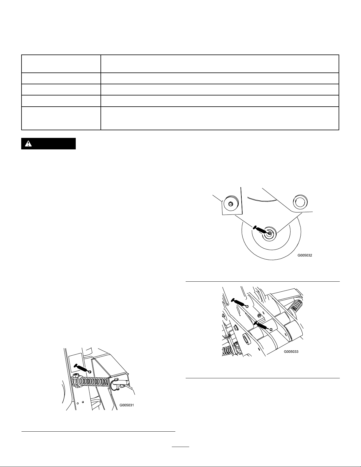
GreasingthePlow
ServiceInterval:Beforeeachuseordaily
Beforestorage
Greasethe6ttings,asshowninFigure11through
Figure14,every8operatinghours.Greaseallttings
immediatelyaftereverywashing.
GreaseType:General-purposegrease
1.Parkthemachineonalevelsurface,disengage
theauxiliaryhydraulicslever,lowerthe
attachment,andengagetheparkingbrake(if
equipped).
2.Shutofftheengineandremovethekey
3.Connectagreaseguntoeachtting.
4.Pumpgreaseintothettingsuntilgreasebegins
tooozeoutofthebearings.
5.Wipeupanyexcessgrease.
g005032
Figure12
g005033
Figure13
Figure11
g005031
10
ChangingtheGearLube
ServiceInterval:Every200hours/Yearly(whichever
comesrst)
1.Parkthemachineonalevelsurface,disengage
theauxiliaryhydraulicslever,andlowerthe
attachmentsothattheplowisontheground.
Engagetheparkingbrake(ifequipped).
Figure14
ServicingtheGearLube
Gear-lubetype:SAE90-140APIserviceGL-4orGL-5
Capacity:1.4L(47oz)
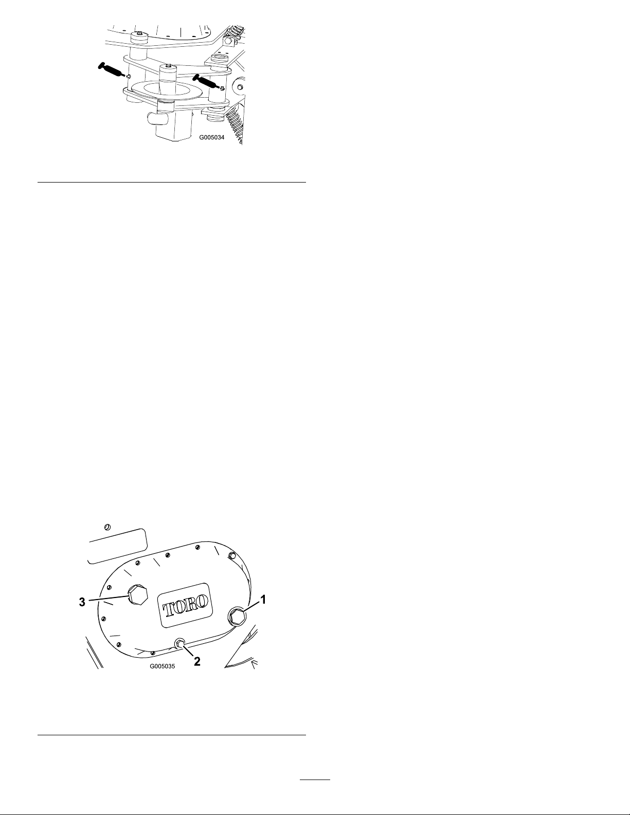
CheckingtheGear-LubeLevel
ServiceInterval:Every25hours
Beforestorage
1.Parkthemachineonalevelsurface,disengage
theauxiliaryhydraulicslever,andlowerthe
attachmentsothattheplowisontheground.
Engagetheparkingbrake(ifequipped).
2.Stoptheengineandremovethekey.
3.Checktheclearglassgaugeonthesideofthe
gearcase(Figure15).
g005034
2.Stoptheengineandremovethekey.
3.Prepareanappropriatecontainertocatchthe
usedoilundertheplow.
4.Removethedrainplug(Figure15),allowingthe
oiltospilloutintothecontainer.
5.Whennished,replacethedrainplug,ensuring
thatitistight.
6.Removethellplug(Figure15)andllthecase
withgearlubeuntilitislevelwiththereddotin
thegauge.
7.Replacethellplug.
Note:Thegearlubeshouldbeatthelevelof
thereddotinthecenterofthegauge.
4.Ifthegear-lubelevelislow,removethellplug
(Figure15)andllthecasewithgearlubeuntilit
islevelwiththereddotinthegauge.
Figure15
1.Glassgauge
2.Drainplug
5.Replacethellplug.
3.Fillplug
g005035
11
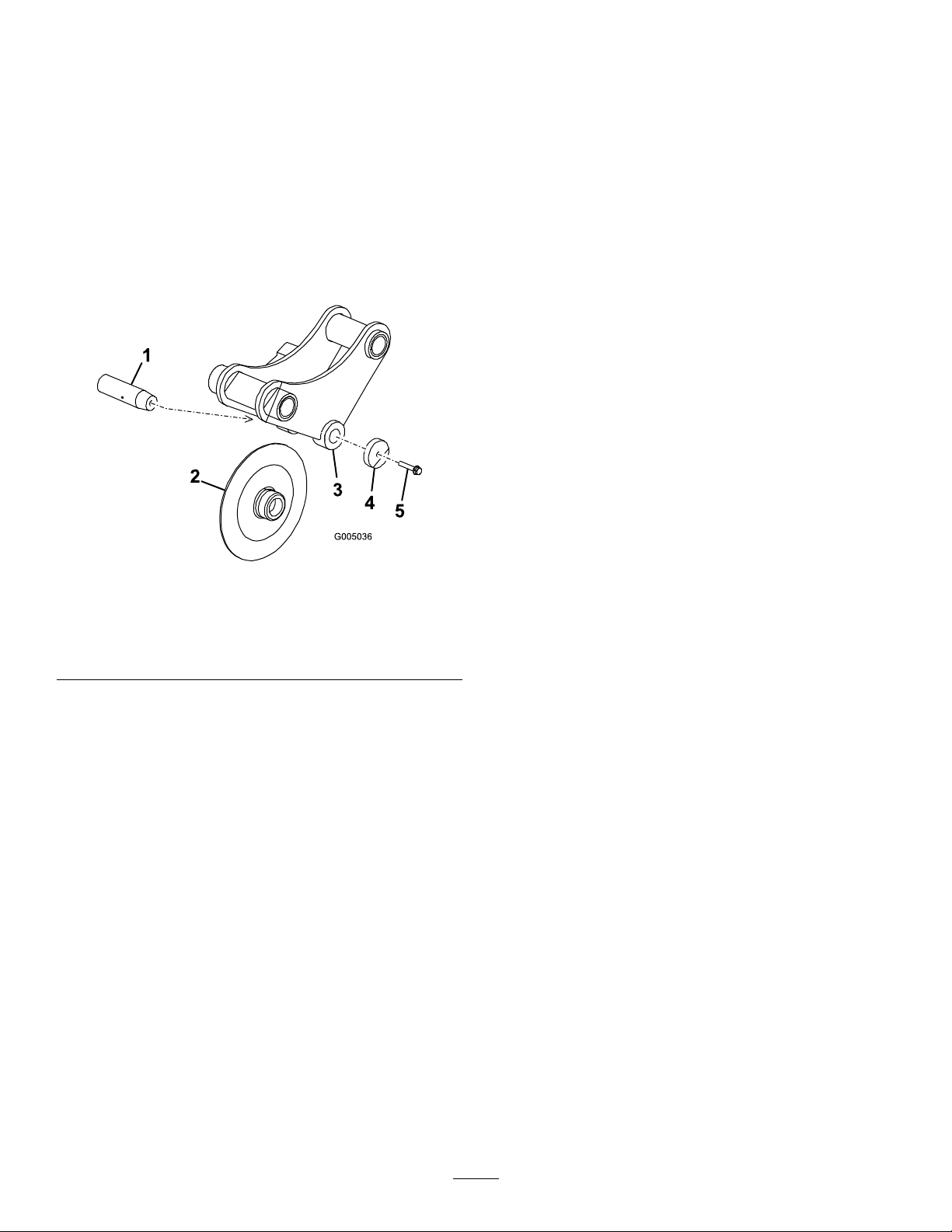
ReplacingtheCoulter
Ifthecoulterbecomesexcessivelywornordamaged,
replaceit.
1.Parkthemachineonalevelsurface,disengage
theauxiliaryhydraulicslever,lowerthe
attachment,andengagetheparkingbrake(if
equipped).
2.Shutofftheengineandremovethekey.
3.Backoutthecoulter-pinscrewabout1.3cm(0.5
inch),thenstrikeitseveraltimeswithahammer
toloosenthepin(Figure16).
Storage
1.Beforelong-termstorage,washtheattachment
withmilddetergentandwatertoremovedirtand
grime.
2.Greasetheplow.
3.Checkgear-caselubrication.
4.Checkandtightenallbolts,nuts,andscrews.
Repairorreplaceanydamagedorwornpart.
5.Ensurethatallhydrauliccouplersareconnected
togethertopreventcontaminationofthe
hydraulicsystem.
6.Paintallscratchedorbaremetalsurfaces.Paint
isavailablefromyourAuthorizedServiceDealer.
7.Storetheattachmentinaclean,drygarageor
storagearea.Coverittoprotectitandkeepit
clean.
Figure16
1.Coulterpin
2.Coulter5.Coulter-pinscrew
3.Coulterbracket
4.Completelyremovethecoulter-pinscrew,
washer,coulter,andcoulterpin(Figure16).
5.Putthenewcoulterintothecoulterbracket
(Figure16).
6.Slidethecoulterpinthroughthebracketand
coulterandsecureitwiththecoulter-pinscrew
andwasher(Figure16).
7.T orquethescrewto61N∙m(45ft-lb).
4.Washer
g005036
12

Troubleshooting
Theplowdoesnotoperate.
Problem
1.Thehydrauliccouplerisnotcompletely
connected.
2.Ahydrauliccouplerisdamaged.
3.Thereisanobstructioninahydraulic
hose.
4.Ahydraulichoseiskinked.4.Replacethekinkedhose
5.Theauxiliaryvalveonthetractionunit
isnotopening.
PossibleCauseCorrectiveAction
1.Checkandtightenallcouplers.
2.Checkthecouplersandreplaceany
thataredamaged.
3.Findandremovetheobstruction.
5.Repairthevalve.
13

DeclarationofIncorporation
TheT oroCompany,8111LyndaleAvenueSouth,Bloomington,MN,USAdeclaresthatthefollowingunit(s)
conform(s)tothedirectiveslisted,wheninstalledinaccordancewiththeaccompanyinginstructionsontocertain
ToromodelsasindicatedontherelevantDeclarationsofConformity.
ModelNo.
22911404320000andUpVibratoryPlow
SerialNo.
ProductDescriptionInvoiceDescription
VIBRATORYPLOW
ATT ACHMENTCE
GeneralDescription
VibratoryPlow
Directive
2006/42/EC
RelevanttechnicaldocumentationhasbeencompiledasrequiredperPartBofAnnexVIIof2006/42/EC.
Wewillundertaketotransmit,inresponsetorequestsbynationalauthorities,relevantinformationonthispartly
completedmachinery.Themethodoftransmissionshallbeelectronictransmittal.
ThismachineryshallnotbeputintoserviceuntilincorporatedintoapprovedToromodelsasindicatedonthe
associatedDeclarationofConformityandinaccordancewithallinstructions,wherebyitcanbedeclaredin
conformitywithallrelevantDirectives.
Certied:
JoeHager
Sr.EngineeringManager
811 1LyndaleAve.South
Bloomington,MN55420,USA
February28,2019
AuthorizedRepresentative:
MarcelDutrieux
ManagerEuropeanProductIntegrity
ToroEuropeNV
Nijverheidsstraat5
2260Oevel
Belgium

EuropeanPrivacyNotice
TheInformationToroCollects
ToroWarrantyCompany(T oro)respectsyourprivacy.Inordertoprocessyourwarrantyclaimandcontactyouintheeventofaproductrecall,weaskyou
tosharecertainpersonalinformationwithus,eitherdirectlyorthroughyourlocalT orocompanyordealer.
TheT orowarrantysystemishostedonserverslocatedwithintheUnitedStateswhereprivacylawmaynotprovidethesameprotectionasapplies
inyourcountry.
BYSHARINGYOURPERSONALINFORMATIONWITHUS,YOUARECONSENTINGTOTHEPROCESSINGOFYOURPERSONALINFORMATION
ASDESCRIBEDINTHISPRIV ACYNOTICE.
TheWayT oroUsesInformation
Toromayuseyourpersonalinformationtoprocesswarrantyclaims,tocontactyouintheeventofaproductrecallandforanyotherpurposewhichwetell
youabout.ToromayshareyourinformationwithT oro'safliates,dealersorotherbusinesspartnersinconnectionwithanyoftheseactivities.Wewillnot
sellyourpersonalinformationtoanyothercompany.Wereservetherighttodisclosepersonalinformationinordertocomplywithapplicablelawsand
withrequestsbytheappropriateauthorities,tooperateoursystemsproperlyorforourownprotectionorthatofotherusers.
RetentionofyourPersonalInformation
Wewillkeepyourpersonalinformationaslongasweneeditforthepurposesforwhichitwasoriginallycollectedorforotherlegitimatepurposes
(suchasregulatorycompliance),orasrequiredbyapplicablelaw .
Toro'sCommitmenttoSecurityofYourPersonalInformation
Wetakereasonableprecautionsinordertoprotectthesecurityofyourpersonalinformation.Wealsotakestepstomaintaintheaccuracyandcurrent
statusofpersonalinformation.
AccessandCorrectionofyourPersonalInformation
Ifyouwouldliketorevieworcorrectyourpersonalinformation,pleasecontactusbyemailatlegal@toro.com.
AustralianConsumerLaw
AustraliancustomerswillnddetailsrelatingtotheAustralianConsumerLaweitherinsidetheboxoratyourlocalToroDealer.
374-0282RevC

CaliforniaProposition65WarningInformation
Whatisthiswarning?
Youmayseeaproductforsalethathasawarninglabellikethefollowing:
WARNING:CancerandReproductiveHarm—www.p65Warnings.ca.gov.
WhatisProp65?
Prop65appliestoanycompanyoperatinginCalifornia,sellingproductsinCalifornia,ormanufacturingproductsthatmaybesoldinorbroughtinto
California.ItmandatesthattheGovernorofCaliforniamaintainandpublishalistofchemicalsknowntocausecancer,birthdefects,and/orother
reproductiveharm.Thelist,whichisupdatedannually,includeshundredsofchemicalsfoundinmanyeverydayitems.ThepurposeofProp65isto
informthepublicaboutexposuretothesechemicals.
Prop65doesnotbanthesaleofproductscontainingthesechemicalsbutinsteadrequireswarningsonanyproduct,productpackaging,orliteraturewith
theproduct.Moreover,aProp65warningdoesnotmeanthataproductisinviolationofanyproductsafetystandardsorrequirements.Infact,the
CaliforniagovernmenthasclariedthataProp65warning“isnotthesameasaregulatorydecisionthataproductis‘safe’or‘unsafe.’”Manyofthese
chemicalshavebeenusedineverydayproductsforyearswithoutdocumentedharm.Formoreinformation,gotohttps://oag.ca.gov/prop65/faqs-view-all
AProp65warningmeansthatacompanyhaseither(1)evaluatedtheexposureandhasconcludedthatitexceedsthe“nosignicantrisklevel”;or(2)
haschosentoprovideawarningbasedonitsunderstandingaboutthepresenceofalistedchemicalwithoutattemptingtoevaluatetheexposure.
Doesthislawapplyeverywhere?
Prop65warningsarerequiredunderCalifornialawonly.ThesewarningsareseenthroughoutCaliforniainawiderangeofsettings,includingbutnot
limitedtorestaurants,grocerystores,hotels,schools,andhospitals,andonawidevarietyofproducts.Additionally ,someonlineandmailorder
retailersprovideProp65warningsontheirwebsitesorincatalogs.
.
HowdotheCaliforniawarningscomparetofederallimits?
Prop65standardsareoftenmorestringentthanfederalandinternationalstandards.TherearevarioussubstancesthatrequireaProp65warning
atlevelsthatarefarlowerthanfederalactionlimits.Forexample,theProp65standardforwarningsforleadis0.5μg/day,whichiswellbelow
thefederalandinternationalstandards.
Whydon’tallsimilarproductscarrythewarning?
•ProductssoldinCaliforniarequireProp65labellingwhilesimilarproductssoldelsewheredonot.
•AcompanyinvolvedinaProp65lawsuitreachingasettlementmayberequiredtouseProp65warningsforitsproducts,butothercompanies
makingsimilarproductsmayhavenosuchrequirement.
•TheenforcementofProp65isinconsistent.
•CompaniesmayelectnottoprovidewarningsbecausetheyconcludethattheyarenotrequiredtodosounderProp65;alackofwarningsfora
productdoesnotmeanthattheproductisfreeoflistedchemicalsatsimilarlevels.
WhydoesToroincludethiswarning?
Torohaschosentoprovideconsumerswithasmuchinformationaspossiblesothattheycanmakeinformeddecisionsabouttheproductstheybuyand
use.T oroprovideswarningsincertaincasesbasedonitsknowledgeofthepresenceofoneormorelistedchemicalswithoutevaluatingthelevelof
exposure,asnotallthelistedchemicalsprovideexposurelimitrequirements.WhiletheexposurefromT oroproductsmaybenegligibleorwellwithinthe
“nosignicantrisk”range,outofanabundanceofcaution,T orohaselectedtoprovidetheProp65warnings.Moreover ,ifTorodoesnotprovidethese
warnings,itcouldbesuedbytheStateofCaliforniaorbyprivatepartiesseekingtoenforceProp65andsubjecttosubstantialpenalties.
RevA
 Loading...