


FormNo.3356-322RevB
VibratoryPlow
forCompactUtilityLoaders
ModelNo.22911—SerialNo.270000001andUp
Registeratwww.T oro.com.OriginalInstructions(EN)
Theremaybeburiedpower,gas,and/or
telephonelinesintheworkarea.Shockor
explosionmayoccurifyoudigintothem.
Havethepropertyorworkareamarkedfor
buriedlinesanddonotdiginmarkedareas.
Contactyourlocalmarkingserviceorutility
companytohavethepropertymarked(for
example,intheUnitedStates,call811forthe
nationwidemarkingservice).
Introduction
Readthisinformationcarefullytolearnhowtooperate
andmaintainyourproductproperlyandtoavoidinjury
andproductdamage.Youareresponsibleforoperating
theproductproperlyandsafely.
YoumaycontactTorodirectlyatwww .Toro.comfor
productandaccessoryinformation,helpndinga
dealer,ortoregisteryourproduct.
Wheneveryouneedservice,genuineToroparts,or
additionalinformation,contactanAuthorizedService
DealerorToroCustomerServiceandhavethemodel
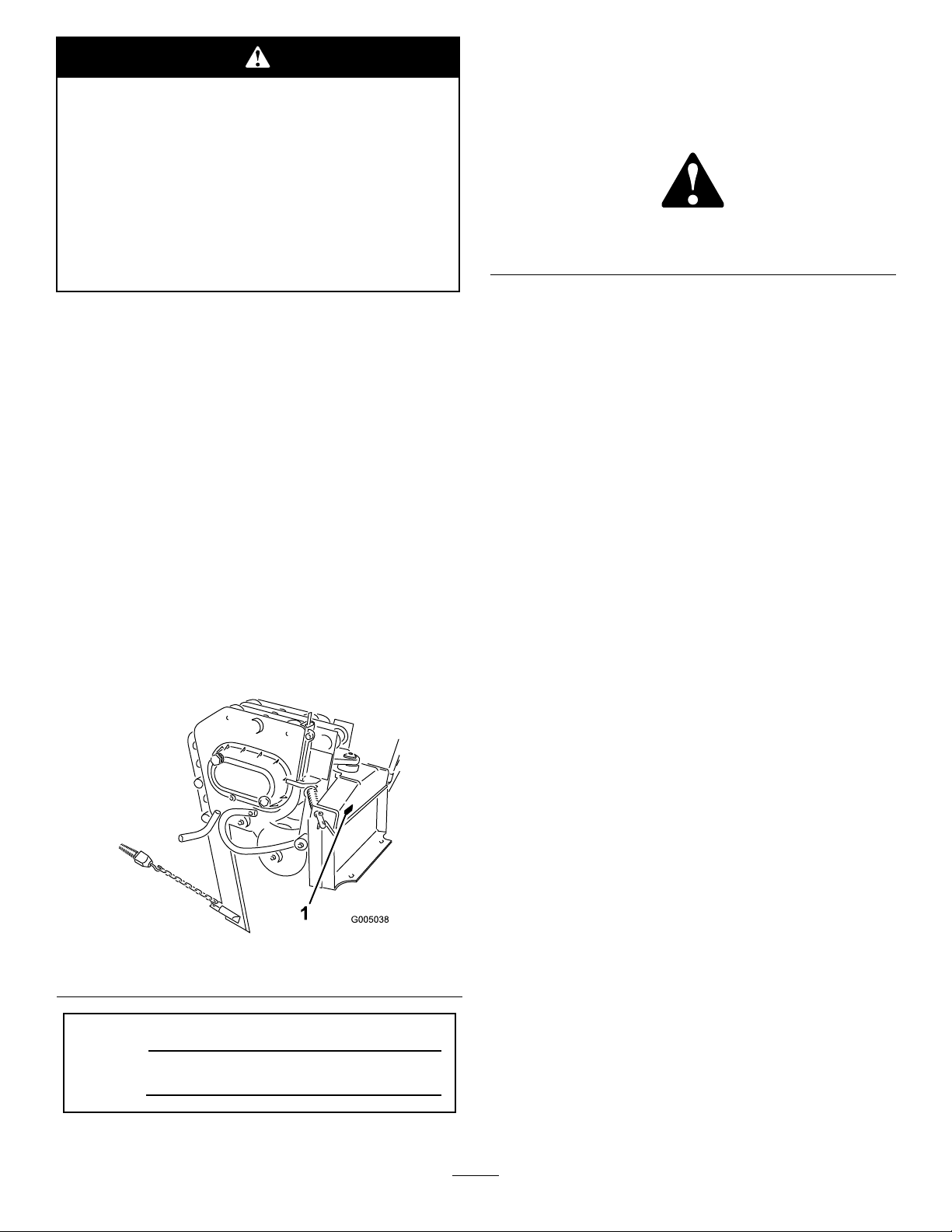
andserialnumbersofyourproductready .Figure1
identiesthelocationofthemodelandserialnumbers
ontheproduct.Writethenumbersinthespace
provided.
Figure1
1.Modelandserialnumberlocation
Thismanualidentiespotentialhazardsandhas
safetymessagesidentiedbythesafetyalertsymbol
(Figure2),whichsignalsahazardthatmaycauseserious
injuryordeathifyoudonotfollowtherecommended
precautions.
Figure2
1.Safetyalertsymbol
Thismanualalsouses2wordstohighlightinformation.
Importantcallsattentiontospecialmechanical
informationandNoteemphasizesgeneralinformation
worthyofspecialattention.
Contents
Introduction.................................................................2
Safety...........................................................................3
StabilityRatings....................................................4
SoundPressureLevel...........................................4
VibrationLevel.....................................................4
SafetyandInstructionalDecals.............................5
ProductOverview........................................................5
Specications.......................................................5
Attachments/Accessories.....................................5
Operation.....................................................................6
InstallingaBlade..................................................6
Plowing................................................................6
GaugingPlowDepth............................................7
TransportingthePlow..........................................8
RemovingthePlowfromtheTraction
Unit..................................................................8
OperatingTips.....................................................8
Maintenance.................................................................9
RecommendedMaintenanceSchedule(s)..................9
GreasingthePlow................................................9
ServicingtheGearLube.....................................10
ReplacingtheCoulter.........................................11
Storage.......................................................................11
Troubleshooting.........................................................12
ModelNo.
SerialNo.
©2007—TheToro®Company
8111LyndaleAvenueSouth
Bloomington,MN55420
Contactusatwww.Toro.com.
2
PrintedintheUSA.
AllRightsReserved
Safety
Improperuseormaintenancebytheoperatoror
ownercanresultininjury.T oreducethepotential
forinjury,complywiththesesafetyinstructionsand
thoseinthetractionunit
payattentiontothesafetyalertsymbol,which
means
safetyinstruction.Failuretocomplywiththe
instructionmayresultinpersonalinjuryordeath.
Caution
Contactwiththemovingplowcancuthands,
feet,orotherbodyparts.
•Keepyourhands,feet,andanyotherpart
ofyourbodyorclothingawayfrommoving
parts.
•Beforeadjusting,cleaning,repairing,and
inspectingtheplow,lowerittotheground,
stoptheengine,removethekey ,andwaitfor
allmovingpartstostop.
,
W ar ning
Operator’ s Man ual
,or
Danger
—personal
.Always
Whengoingupordownhill,themachinecould
overturniftheheavyendistowardthedownhill
side.Someonemaybepinnedorseriously
injuredbythemachineifitoverturns.
Operateupanddownslopeswiththeheavyend
ofthemachineuphill.Anattachedplowwill
makethefrontendheavy.
Ifyoudonotfullyseattheattachmentlocking
pinsintheattachmentmountplateholes,the
attachmentcouldfalloffofthetractionunit
severelyinjuringtheoperatororbystanders.
•Ensurethatyoufullyseattheattachment
lockingpinsthroughtheholesinthe
attachmentmountplatebeforeliftingthe
attachment.
•Ensurethattheattachmentmountplateis
freeofanydirtordebristhatmayhinder
theconnectionofthetractionunittothe
attachment.
Theremaybeburiedpower,gas,and/or
telephonelinesintheworkarea.Shockor
explosionmayoccurifyoudigintothem.
Havethepropertyorworkareamarkedfor
buriedlinesanddonotdiginmarkedareas.
Contactyourlocalmarkingserviceorutility
companytohavethepropertymarked(for
example,intheUnitedStates,call811forthe
nationwidemarkingservice).
Whentheengineisoff,attachmentsinthe
raisedpositioncangraduallylower.Someone
nearbymaybepinnedorinjuredbythe
attachmentasitlowers.
Alwayslowertheattachmentlifteachtimeyou
shutoffthetractionunit.
•Refertoyourtractionunit
Man ual
connectinganattachmenttoyourtraction
unit.
Theplowisveryloudduringoperation;
overtime,yourhearingmaybeimpairedif
unprotected.
Wearhearingprotectionduringoperation.
fordetailedinformationonsafely
Operator’ s
3

Whentheplowisoutoftheground,bystanders
couldbeinjuredbytheswingingplow,and/or
thetractionunitcouldbeoverturnedbythe
inertiaoftheswingingplow,crushingyouor
bystanders.
•Keeptheplowlowatalltimes.
•Usecautionwhenturninganddonotturn
quickly.
•Keepallbystandersatleast6ft.(2meters)
awaywhileoperating.
OrientationStabilityRating
FrontUphill
C
RearUphill
D
SideUphill
C
Hydrauliccouplers,hydrauliclines/valves,and
hydraulicuidmaybehotandcanburnyouif
youtouchthem.
•Weargloveswhenoperatingthehydraulic
couplers.
•Allowthetractionunittocoolbefore
touchinghydrauliccomponents.
•Donottouchhydraulicuidspills.
StabilityRatings
Todeterminethedegreeofslopeyoucantraversewith
theplowinstalledonatractionunit,ndthestability
ratingforthehillpositionyouwanttotravelinthe
appropriatetablebelow ,thenndthedegreeofslope
forthesameratingandhillpositionintheStabilityData
sectionofthetractionunitOperator’sManual.
SoundPressureLevel
Thisunithasamaximumsoundpressureatthe
operator’searof117dB(A),basedonmeasurements
whenoperatedonatractionunitperEN11201.The
soundpressurelevelwillvarydependingonconditions.
VibrationLevel
Thisunithasamaximumhand-armvibrationlevelof7
2
m/s
andwholebodyvibrationlevelof0.2m/s
onmeasurementsofidenticalmachinesperEN1033
andEN1032.
2
based
Exceedingthemaximumrecommendedslope
cancausethetractionunittotip,crushingyou
orbystanders.
Donotdrivethetractionunitonaslopesteeper
thanthemaximumrecommendedslope,as
determinedinthefollowingtablesandthe
tractionunit
Important:Ifyouhaveatractionunitotherthan
aTXcompactutilityloader,usethecounterweight
onthetractionunitwhenusingtheplow .Failureto
usethecounterweightwillcausethetractionunitto
becomeunstable.
Operator’ s Man ual
.
4

SafetyandInstructional
Decals
Safetydecalsandinstructionsareeasily
visibletotheoperatorandarelocated
nearanyareaofpotentialdanger.
Replaceanydecalthatisdamagedor
lost.
100-4649
1.Explosionandelectricshockhazards—donotdiginareas
withburiedgasorelectricallines,keepbystandersasafe
distancefromthemachine.
ProductOverview
1.Vibratoryplowbody
2.Blade(severaloptional
bladestylesareavailable)
3.Puller(severaloptional
pullerstylesareavailable)
Figure3
4.Gaugerodassembly
5.Coulter
6.Mountingplate
100-4650
1.Crushinghazardofhand—keepbystandersasafedistance
fromthemachine.
2.Crushinghazardoffoot—keepbystandersasafedistance
fromthemachine.
Specications
Note:Specicationsanddesignaresubjecttochange
withoutnotice.
Width
Length
Height
Weight
Hydraulicmotordisplacement
Plowcycles2,000VPM
Attachments/Accessories
AselectionofToroapprovedattachmentsand
accessoriesareavailableforusewiththemachineto
enhanceandexpanditscapabilities.Contactyour
AuthorizedServiceDealerorDistributororgoto
www.Toro.comforalistofallapprovedattachments
andaccessories.
29inches(73.6cm)
35inches(89cm)
24inches(60cm)
400lb(181.5Kg)
1.27in3/rev(20.8cc)
5

Operation
RefertoyourtractionunitOperator’sManualformore
informationoninstallingandremovingattachments
onyourtractionunit.
Important:Alwaysusethetractionunittoliftand
movetheattachment.
InstallingaBlade
Torooffersseveraldifferentbladesandpullers.
PurchaseabladeandpullerfromyourTorodealer.
Plowing
1.Movethelynchpinstotheoutsideholesonthe
springrodstoallowtheplowtomovefromside
toside(Figure5).
Thebladeissharpandcanswingduring
installationandremoval,cutting,pinching,or
crushinghandsorfeet.
Wearglovesandworkbootsandsecurelyhold
theblade.
1.Raisetheplowabout36inches(1m)offofthe
groundandinstallthecylinderlock(s).
2.Stoptheengineandremovethekey.
3.Removethetwoclickpinsfromtheclevispins
inthebladebracket,thenremovetheclevispins
(Figure4)andtheexistingblade(ifinstalled).
Figure5
1.Outerhole3.Springrod
2.Lynchpin(ininnerhole)
Whenyouremovethelynchpin,theplowcould
swingintoyouorabystander,orcausethe
tractionunittobecomeunstable.
Holdtheplowintheneutralpositionwhen
movingthelynchpins.
2.Connectthematerialbeinginstalledtotheplow.
3.Ifyourtractionunithasaspeedselector,moveitto
theslow(turtle)position.
4.Starttheengine.
5.Tilttheattachmentplatecompletelybacksothatthe
topoftheplowisparalleltotheground(Figure7).
6.Lowertheplowsothatitisrestingontheground.
Figure4
1.Clickpin
2.Clevispin
4.Slidethenewbladeintothebladebracketandsecure
itatthedesireddepth(achangeinmountingholes
willchangethedepthby3inches(7.6cm)),using
theclevispinsandclickpinsremovedpreviously
(Figure4).
3.Blade
Important:Alwaysensurethattheplowison
orinthegroundbeforeengagingtheauxiliary
hydraulicslever.Failuretodosowillcause
excessivevibrationofthetractionunit,possibly
resultingindamage.
Note:Ifyoudigaholetolowerthebladeinto
beforestarting,itwillreducetheriskofbending
theblade.
7.Pulltheauxiliaryhydraulicslevertotheoperator
griptoengagetheplow.
8.Slowlylowertheplowintothegroundtothedesired
depth,whilemovingthetractionunitbackward.
9.Whennished,releasetheauxiliaryhydraulicslever
tostoptheplow .
6

Whenplowingonahill,theplowcanswing
downhillwhenraisedoutofthesoil.Duetothe
weightoftheplow,ifitswingstoofast,theforce
couldtipthetractionunitinjuringyouorothers.
Whenplowingonahill,raisetheplowoutof
thegroundslowly,lettingitswingwhilethe
bulletisstillinthesoil.
10.Raisetheplowoutofthegroundfarenoughtopull
thepulleroutofthesoil.
11.Movethetractionunitrearwardtopullouta
workinglengthofmaterial,thenmoveforward
slightlytocreatesomeslackintheline.
12.Stoptheengine.
GaugingPlowDepth
Normally,youwillbeplowingatthemaximumdepth
setbytheblade;however,theplowisalsoequipped
withagaugetoallowyoutolifttheplowanddetermine
howhighabovemaximumdepthyouareplowing.
Thegaugeislocatedontheleftsideoftheplowfacing
thetractionunit.Arodassemblyrunsfromthegauge
totheground.Whentheplowislifted,theindicatoron
thegaugemovesdown.Marksonthegaugeshowthe
numberofincheslowerorhigherthanthemaximum
depththatyouareplowing.Thegaugereadsfrom
+2to-3inches(+5to-7.6cm),withzerobeingthe
maximumdepthonbaregroundand-3being3inches
(7.6cm)abovemaximumdepth.Figure6andFigure7
illustratethegauge.
Figure7
1.Gaugerodassembly
2.Paralleltotheground
Whenplowingbareground,maximumdepthis
indicatedonthegaugeasthezeromark.Youcan
plowdowntothe+1mark,butinthiscaseyouwillbe
contactingthegroundwiththecoulteraxle.Plowing
anylowermaydamagethecoulter.
Whenplowinggrasscoveredground,thegaugewill
readaboutaninchlowerthantheactualdepthbecause
ofthegrass.Inthiscase,lowertheplowtothedesired
coulterdepthandnotethereadingonthegauge.
Ifyouaretransportingtheploworareplowingrough
terrain,youcanlockthegaugeatthe+2position
tokeepitfrombeingdamaged.Tolockthegauge,
manuallyraiseittothe+2positionandmovethe
lockinglevertotheleft.
1.Depthgauge
Figure6
2.Gaugelockinglever
7
TransportingthePlow
1.Movethelynchpinstotheinsideholesonthespring
rodstopreventsidetosidemovement(Figure5).
Failuretosecuretheplowwillallowittoswing
sidetosideandunbalancetheplow.Duetothe
weightoftheplow,ifitswingstoofast,theforce
couldtipthetractionunitinjuringyouorothers.
Alwayssecuretheplowwiththelynchpins
intheinnerholesofthespringrodsbefore
transportingtheplow.
2.Raisetheloaderarmsjustenoughtoensurethatthe
bladeclearstheground.
OperatingTips
•Someoldermodeltractionunitshaveholesthrough
thespringandquickattachpinsonthemountplate
(Figure9)toallowyoutoinstalltwohairpincotters
whenplowinglongruns.Thiswillensurethatthe
vibrationoftheplowwillnotcausethepinsto
comeloose.
Note:Thequickattachpinsonnewertraction
unitsnolongerneedthehairpincotters.
Important:Nevertransporttheplowwiththe
armsfullyraised.
RemovingthePlowfromthe
TractionUnit
RefertoyourtractionunitOperator’sManualfor
completeinstructionsonremovingattachmentsfrom
thetractionunitanddisconnectinghydraulichoses.
1.Withtheplowraisedabovetheground,stopthe
engine.
2.Removethelowerclickpinandclevispinsecuring
thebladetotheplow(tocompletelyremovethe
blade,removeboththeupperandlowerclickand
clevispins)(Figure4).
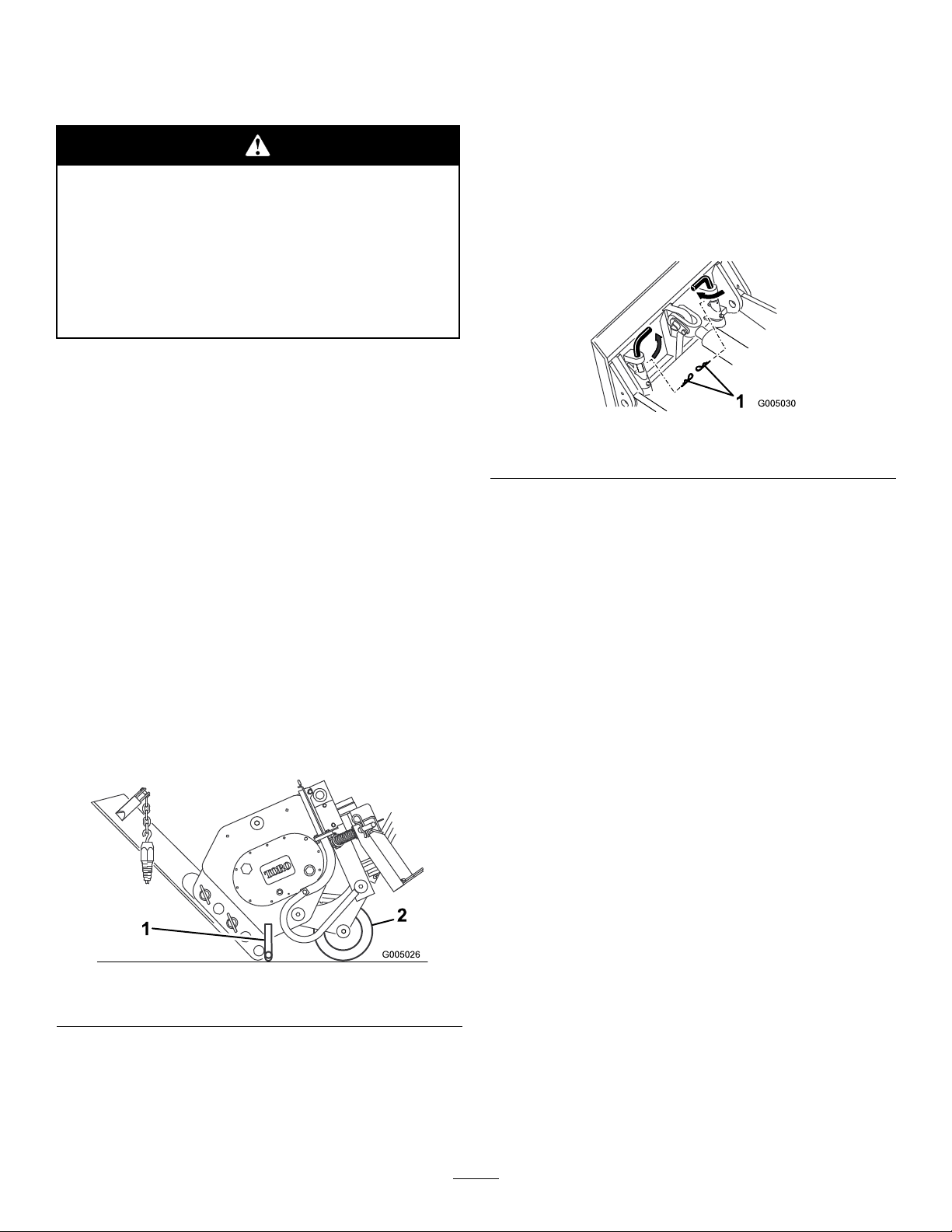
3.Swingthebladeupandsecureitasillustratedin
Figure8.
Figure9
1.Hairpincotters
•Toreducewearonthetractionunitdrivechain(if
yourmodelhasone),tightenthechainsothereis
only2inches(5cm)ofslackontheupperspan
(refertoyourtractionunitOperator’sManualfor
instructions).
•Cleantheareaoftrash,branchesandrocksbefore
plowingtopreventequipmentdamage.
•Alwaysbeginplowingwiththeslowestground
speedpossible.Increasespeedifconditionspermit,
butdonotallowthetiresortrackstospin.Spinning
thetracksortireswillcauseturfdamageandplace
stressonthetractionunit.
•Alwaysusefullthrottle(maximumenginespeed)
whenplowing.
•Alwaysplowbackwards(i.e.,inreverse).
•Ifyourtractionunithasaspeedselectorandaow
divider,movethespeedselectortoslow(turtle)and
theowdividertothe10o’clockposition.
Figure8
1.Stand2.Coulter
4.Tilttheplowforwardandlowerittothegroundor
trailer,withthestandandcoultersupportingthe
weightoftheplow(Figure8).
5.Stoptheengineandremovetheplowasdirectedin
yourtractionunitOperator’ sManual.
•Avoidsharpturnswhenplowingtoincrease
productivityandminimizegrounddisturbance.
•Ifyourtractionunithastiresandyouhavethe
agriculturalorSiteworkSystemstiresinstalledon
thetractionunit,removethetiresandmovethe
rightsidetirestotheleftandtheleftsidetiresto
theright.Thiswillensurethatthetiretreadpoints
tothereartogiveyouthemosttractionwhenusing
thevibratoryplow .
8

Maintenance
RecommendedMaintenanceSchedule(s)
MaintenanceService
Interval
Beforeeachuseordaily
Every25hours
Every200hours
Beforestorage
MaintenanceProcedure
•Greasetheplow .
•Checkthegearlubelevel.
•Changethegearlube.
•Greasetheplow .
•Checkthegearlubelevel.
•Paintchippedsurfaces.
Ifyouleavethekeyintheignitionswitch,someonecouldstarttheengine.Accidentalstartingofthe
enginecouldseriouslyinjureyouorotherbystanders.
Removethekeyfromtheignitionswitchbeforeyoudoanymaintenance.
GreasingthePlow
ServiceInterval:Beforeeachuseordaily
Beforestorage
Grease6ttings,asshowninFigure10through
Figure13,every8operatinghours.Greaseallttings
immediatelyaftereverywashing.
GreaseType:General-purposegrease
1.Stoptheengineandremovethekey.
2.Cleanthegreasettingswitharag.
3.Connectagreaseguntoeachtting.
4.Pumpgreaseintothettingsuntilgreasebeginsto
oozeoutofthebearings.
5.Wipeupanyexcessgrease.
Figure11
Figure12
Figure10
9
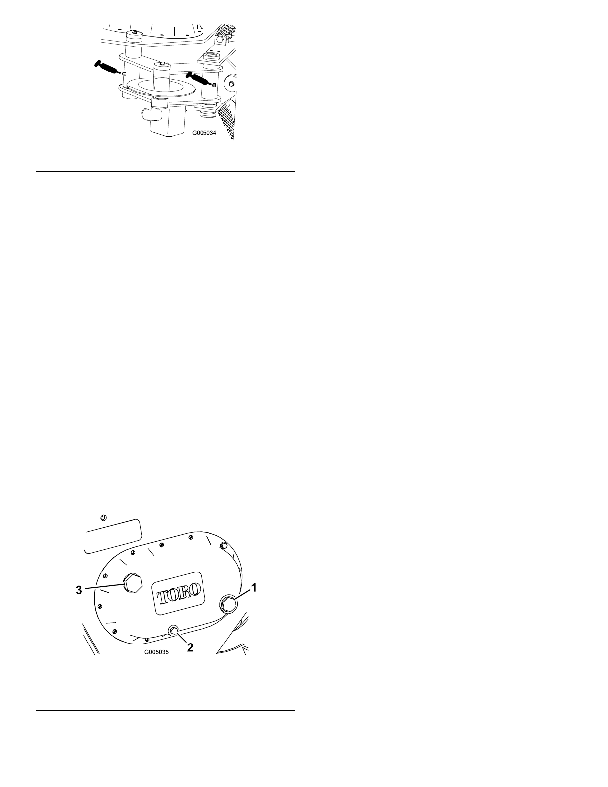
Figure13
ChangingtheGearLube
ServiceInterval:Every200hours
1.Positionthetractionunitandplowonalevelsurface
andlowertheattachmentliftsothattheplowison
theground.
2.Stoptheengineandremovethekey.
3.Prepareanappropriatecontainertocatchtheused
oilundertheplow .
4.Removethedrainplug(Figure14),allowingtheoil
tospilloutintothecontainer.
ServicingtheGearLube
Checkthegearlubricationoillevelinthegearcaseevery
25operatinghoursandchangeitevery200operating
hoursoronceayear,whicheveroccursrst.
Gearlubetype:SAE90-140APIserviceGL-4orGL-5
Rellcapacity:3pints.
CheckingtheGearLubeLevel
ServiceInterval:Every25hours
Beforestorage
1.Positionthetractionunitandplowonalevelsurface
andlowertheattachmentliftsothattheplowison
theground.
2.Stoptheengineandremovethekey.
3.Checktheclearglassgaugeonthesideofthegear
case(Figure14).Thegearlubeshouldbeatthelevel
ofthereddotinthecenterofthegauge.
4.Ifthegearlubelevelislow,removethellplug
(Figure14)andllthecasewithgearlubeuntilitis
levelwiththereddotinthegauge.
5.Whennished,replacethedrainplug,ensuringthat
itistight.
6.Removethellplug(Figure14)andllthecasewith
gearlubeuntilitislevelwiththereddotinthegauge.
7.Replacethellplug.
1.Glassgauge
2.Drainplug
5.Replacethellplug.
Figure14
3.Fillplug
10

ReplacingtheCoulter
Ifthecoulterbecomesexcessivelywornordamaged,
replaceit.
1.Backoutthecoulterpinscrewabout0.5inch(1.3
cm),thenstrikeitseveraltimeswithahammerto
loosenthepin(Figure15).
Figure15
1.Coulterpin
2.Coulter5.Coulterpinscrew
3.Coulterbracket
4.Washer
Storage
1.Beforelongtermstorage,washtheattachmentwith
milddetergentandwatertoremovedirtandgrime.
2.Greasetheplow.
3.Checkgearcaselubrication.
4.Checkandtightenallbolts,nuts,andscrews.Repair
orreplaceanydamagedorwornpart.
5.Ensurethatallhydrauliccouplersareconnected
togethertopreventcontaminationofthehydraulic
system.
6.Paintallscratchedorbaremetalsurfaces.Paintis
availablefromyourAuthorizedServiceDealer.
7.Storetheattachmentinaclean,drygarageorstorage
area.Coverittoprotectitandkeepitclean.
2.Completelyremovethecoulterpinscrew ,washer,
coulter,andcoulterpin(Figure15).
3.Putthenewcoulterintothecoulterbracket
(Figure15).
4.Slidethecoulterpinthroughthebracketandcoulter
andsecureitwiththecoulterpinscrewandwasher
(Figure15).
5.Torquethescrewto45ft-lb(61N-m).
11

Troubleshooting
Theplowdoesnotoperate.
Problem
1.Thehydrauliccouplerisnotcompletely
connected
2.Ahydrauliccouplerisdamaged.
3.Thereisanobstructioninahydraulic
hose.
4.Ahydraulichoseiskinked.4.Replacethekinkedhose
5.Theauxiliaryvalveonthetractionunit
isnotopening.
PossibleCauseCorrectiveAction
1.Checkandtightenallcouplers.
2.Checkthecouplersandreplaceany
thataredamaged.
3.Findandremovetheobstruction.
5.Repairthevalve.
12

Notes:
13

Notes:
14

Notes:
15

Compact Utility Loader
(CUL) Products
The Toro Compact Utility Loader Warranty
A One-Year Limited Warranty
The Toro® Company and its affi liate, Toro Warranty Company, pursuant
Conditions and Products Covered
to an agreement between them, jointly warrant your Toro Compact Utility
Loader (CUL) (“Product”) to be free from defects in materials or workmanship. The following time periods apply from the date the Product is delivered to the original retail purchaser:
The following time periods apply from the date of purchase:
Products Warranty Period
All CUL units and 1 year or 1000 operational
attachments hours, whichever occurs first
Kohler Engines 3 years
All other Engines 2 years
Where a warrantable condition exists, we will repair the Product at no cost
to you including diagnosis, labor, and parts.
Instructions for Obtaining Warranty Service
If you think that your Toro Product contains a defect in materials or workmanship, follow this procedure:
1. Contact any Authorized Toro CUL Service Dealer to arrange service
at their dealership. To locate a dealer convenient to you, access our
website at www.Toro.com. You may also call our Toro Customer Care
Department toll free at 888-577-7466 (U.S. customers) or 877-484-9255
(Canadian customers).
2. Bring the product and your proof of purchase (sales receipt) to the
Service Dealer.
If for any reason you are dissatisfi ed with the Service Dealer’s analysis or
with the assistance provided, contact us at:
LCB Customer Service Department
Toro Warranty Company
8111 Lyndale Avenue South
Bloomington, MN 55420-1196
Toll Free: 888-577-7466 (U.S. customers)
Toll Free: 877-484-9255 (Canada customers)
Owner Responsibilities
You must maintain your Toro Product by following the maintenance procedures described in the Operator’s Manual. Such routine maintenance,
whether performed by a dealer or by you, is at your expense. Parts scheduled for replacement as required maintenance (“Maintenance Parts”), are
warranted for the period of time up to the scheduled replacement time for
that part. Failure to perform required maintenance and adjustments can be
grounds for disallowing a warranty claim.
Not all product failures or malfunctions that occur during the warranty period are defects in materials or workmanship. This express warranty does
not cover the following:
Product failures which result from the use of non-Toro replacement
•
parts, or from installation and use of add-on, modified, or unapproved
accessories
Product failures which result from failure to perform required mainte-
•
nance and/or adjustments
Product failures which result from operating the Product in an abusive,
•
negligent or reckless manner
Parts subject to consumption through use unless found to be defec-
•
tive. Examples of parts which are consumed, or used up, during normal
Product operation include, but are not limited to, digging teeth, tines,
spark plugs, tires, tracks, filters, chains, etc.
Failures caused by outside influence. Items considered to be outside
•
influence include, but are not limited to, weather, storage practices,
contamination, use of unapproved coolants, lubricants, additives, or
chemicals, etc.
Normal “wear and tear” items. Normal “wear and tear” includes, but is
•
not limited to, worn painted surfaces, scratched decals or windows, etc
Any component covered by a separate manufacturer’s warranty
•
Pickup and delivery charges
•
Repair by an Authorized Toro CUL Service Dealer is your sole remedy
under this warranty. Neither The Toro® Company nor Toro Warranty
Company is liable for indirect, incidental or consequential damages
in connection with the use of the Toro Products covered by this warranty, including any cost or expense of providing substitute equipment or service during reasonable periods of malfunction or non-use
pending completion of repairs under this warranty. All implied warranties of merchantability and fitness for use are limited to the duration
of this express warranty. Some states do not allow exclusions of
incidental or consequential damages, or limitations on how long an
implied warranty lasts, so the above exclusions and limitations may
not apply to you. This warranty gives you specific legal rights, and you
may also have other rights which vary from state to state.
Except for the engine warranty coverage and the Emissions warranty refer-
enced below, if applicable, there is no other express warranty.
The Emissions Control System on your Product may be covered by a separate warranty meeting requirements established by the U.S. Environmental
Protection Agency (EPA) or the California Air Resources Board (CARB).
The hour limitations set forth above do not apply to the Emissions Control
System Warranty. Refer to the California Emission Control Warranty Statement printed in you operator’s manual or contained in the engine manufacturer’s documentation for details.
Items and Conditions Not Covered
General Conditions
Customers who have purchased Toro products exported from the United States or Canada should contact their Toro Distributor (Dealer) to obtain guarantee policies for your country, province, or state. If for any reason you are dissatisfied with your Distributor’s service or have difficulty obtaining guarantee
information, contact the Toro importer. If all other remedies fail, you may contact us at Toro Warranty Company.
Countries Other than the United States or Canada
Part Number 374-0181 Rev. A
 Loading...