

Page 1

Vibratory Plow
for Compact Utility Loaders
Model No. 22910—200000001 & Up
Form No. 3353-857 Rev A
Operator’s Manual
Original Instructions (EN)Register your product at www.Toro.com
Page 2
Contents
Introduction 2. . . . . . . . . . . . . . . . . . . . . . . . . . . . . . . .
Safety 2. . . . . . . . . . . . . . . . . . . . . . . . . . . . . . . . . . . . .
Sound Pressure Level 3. . . . . . . . . . . . . . . . . . . . . .
Vibration Level 3. . . . . . . . . . . . . . . . . . . . . . . . . .
Safety Decals 4. . . . . . . . . . . . . . . . . . . . . . . . . . . .
Specifications 4. . . . . . . . . . . . . . . . . . . . . . . . . . . . . . .
Stability Ratings 4. . . . . . . . . . . . . . . . . . . . . . . . . .
Installation 5. . . . . . . . . . . . . . . . . . . . . . . . . . . . . . . . .
Installing a Blade 5. . . . . . . . . . . . . . . . . . . . . . . . .
Removing the Plow from the Traction Unit 5. . . .
Operation 6. . . . . . . . . . . . . . . . . . . . . . . . . . . . . . . . . .
Plowing 6. . . . . . . . . . . . . . . . . . . . . . . . . . . . . . . .
Transporting the Plow 6. . . . . . . . . . . . . . . . . . . . .
Gauging Plow Depth 7. . . . . . . . . . . . . . . . . . . . . .
Tips for Plowing 7. . . . . . . . . . . . . . . . . . . . . . . . . .
Maintenance 8. . . . . . . . . . . . . . . . . . . . . . . . . . . . . . . .
Service Interval Chart 8. . . . . . . . . . . . . . . . . . . . .
Greasing 8. . . . . . . . . . . . . . . . . . . . . . . . . . . . . . . .
Lubrication 9. . . . . . . . . . . . . . . . . . . . . . . . . . . . . .
Replacing the Coulter 9. . . . . . . . . . . . . . . . . . . . .
Storage 10. . . . . . . . . . . . . . . . . . . . . . . . . . . . . . . . .
Troubleshooting 10. . . . . . . . . . . . . . . . . . . . . . . . . . . . .
DANGER signals an extreme hazard that will cause
serious injury or death if the recommended precautions
are not followed.
Page
WARNING signals a hazard that may cause serious injury
or death if the recommended precautions are not followed.
CAUTION signals a hazard that may cause minor or
moderate injury if the recommended precautions are not
followed.
Two other words are also used to highlight information.
“Important” calls attention to special mechanical
information and “Note” emphasizes general information
worthy of special attention.
The left and right side of the machine is determined by
standing in the normal operator’s position.
Safety
Improper use or maintenance by the operator or owner
can result in injury. To reduce the potential for injury,
comply with the safety instructions in the traction unit
operator’s manual and always pay attention to the
safety alert symbol, which means CAUTION,
WARNING, or DANGER—“personal safety
instruction.” Failure to comply with the instruction
may result in personal injury or death.
DANGER
Introduction
We want you to be completely satisfied with your new
product, so feel free to contact your local Authorized
Service Dealer for help with service, genuine replacement
parts, or other information you may require.
Whenever you contact your Authorized Service Dealer or
the factory, always know the model and serial numbers of
your product. These numbers will help the Service Dealer
or Service Representative provide exact information about
your specific product. You will find the model and serial
number on a plate located on the attachment receiver
plate. For your convenience, write the product model and
serial numbers in the space below.
Model No:
Serial No.
The warning system in this manual identifies potential
hazards and has special safety messages that help you and
others avoid personal injury, even death. DANGER,
WARNING and CAUTION are signal words used to
identify the level of hazard. However, regardless of the
hazard, be extremely careful.
POTENTIAL HAZARD
• There may be buried power, gas, and/or
telephone lines in the area being plowed.
WHAT CAN HAPPEN
• Shock or explosion may occur.
HOW TO AVOID THE HAZARD
• Have the area to be plowed marked for buried
lines and do not plow in marked areas.
DANGER
POTENTIAL HAZARD
• Contact with moving plow may cause injury.
WHAT CAN HAPPEN
• The moving plow can cut hands, feet, or other
body parts.
HOW TO AVOID THE HAZARD
• Keep your hands, feet, and any other part of
your body or clothing away from moving parts.
• Before adjusting, cleaning, repairing, and
inspecting the plow, lower it to the ground, stop
the engine, remove the key, and wait for all
moving parts to stop.
W 2005 by The Toro Company
8111 Lyndale Avenue South
Bloomington, MN 55420-1196
Contact us at www.Toro.com
All Rights Reserved
2
Printed in the USA
Page 3

WARNING
WARNING
POTENTIAL HAZARD
• If you do not fully seat the attachment locking
pins in the attachment mount plate holes, the
attachment could fall off of the traction unit.
WHAT CAN HAPPEN
• The attachment could fall rearward onto the
operator, severely injuring him or her.
• Bystanders may be severely injured by the
attachment as it falls.
HOW TO AVOID THE HAZARD
• Ensure that you fully seat the attachment
locking pins through the holes in the
attachment mount plate before lifting the
attachment.
• Ensure that the attachment mount plate is free
of any dirt or debris that may hinder the
connection of the traction unit to the
attachment.
• Refer to your traction unit Operator’s Manual
for detailed information on safely connecting an
attachment to your traction unit.
WARNING
POTENTIAL HAZARD
• When the engine is off, attachments in the
raised position can gradually lower.
WHAT CAN HAPPEN
• Someone nearby may be pinned or injured by
the attachment as it lowers.
HOW TO AVOID THE HAZARD
• Always lower the attachment lift each time you
shut off the traction unit.
POTENTIAL HAZARD
• When the plow is out of the ground, bystanders
could be injured by the swinging plow.
• The traction unit could be overturned by the
inertia of the swinging plow.
WHAT CAN HAPPEN
• You or bystanders could be crushed by the
traction unit or plow.
HOW TO AVOID THE HAZARD
• Keep the plow low at all times.
• Use caution when turning and do not turn
quickly.
• Keep all bystanders at least 6 ft. (2 meters)
away while operating.
CAUTION
POTENTIAL HAZARD
• Hydraulic couplers, hydraulic lines/valves, and
hydraulic fluid may be hot.
WHAT CAN HAPPEN
• Contact with hot hydraulic components or fluid
may cause burns.
HOW TO AVOID THE HAZARD
• Wear gloves when operating the hydraulic
couplers.
• Allow the traction unit to cool before touching
hydraulic components.
• Do not touch hydraulic fluid spills.
Sound Pressure Level
WARNING
POTENTIAL HAZARD
• The plow is very loud during operation.
WHAT CAN HAPPEN
• Over time, your hearing may be impaired if
unprotected.
HOW TO AVOID THE HAZARD
• Wear hearing protection during operation.
This unit has a maximum sound pressure at the operator’s
ear of 117 dB(A), based on measurements when operated
on a traction unit per Directive 81/1051/EEC. The sound
pressure level will vary depending on conditions.
Vibration Level
This unit has a maximum hand-arm vibration level of
7 m/s and whole body vibration level of 0.2 m/s
based on measurements of identical machines per EN
1033 and EN 1032.
3
Page 4
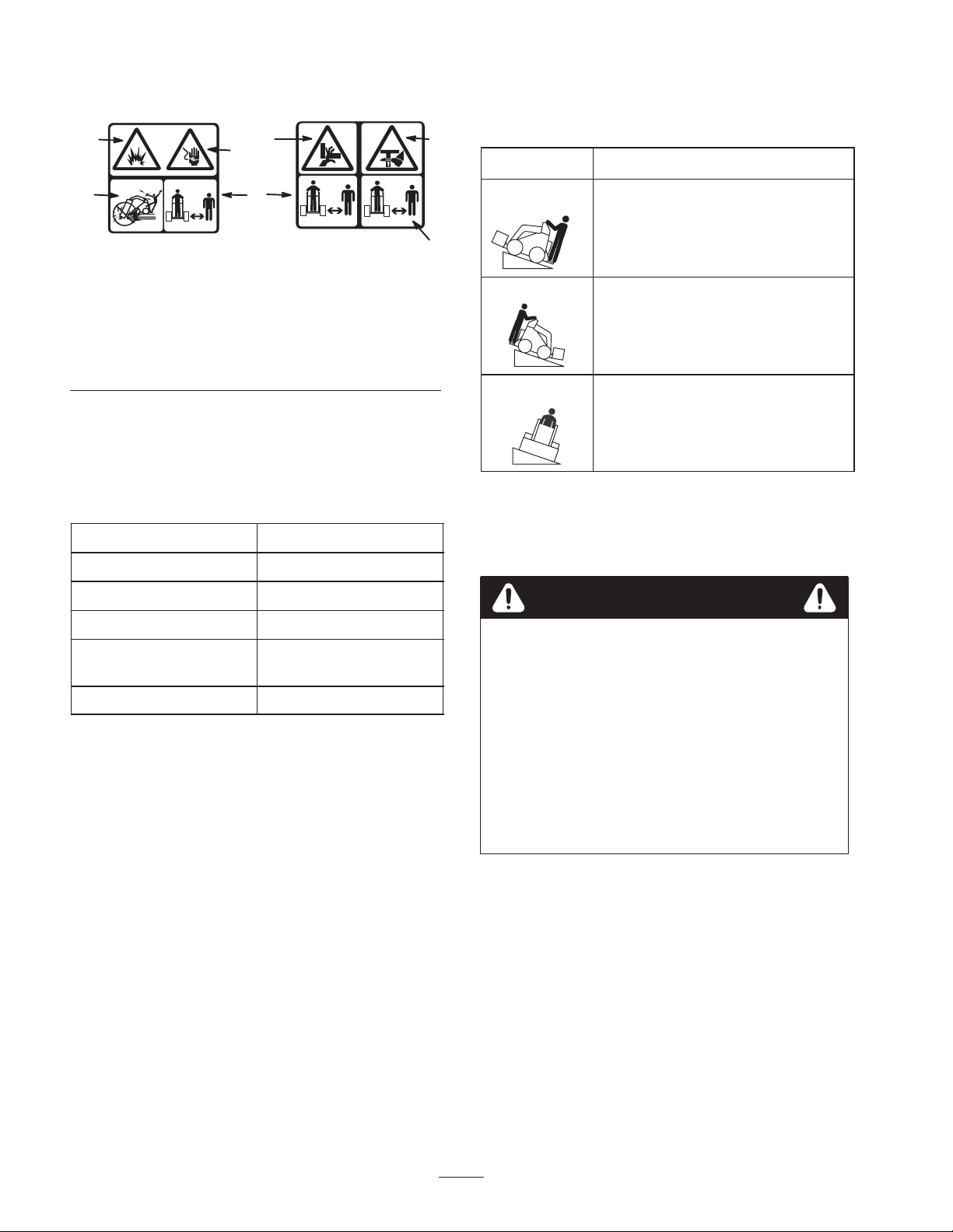
Safety Decals
1
the table below, then find the degree of slope for the same
rating and orientation in the Stability Data section of the
3
2
traction unit operator’s manual.
4
Orientation Stability Rating
5
# 100–4649
1. Explosion hazard
2. Shock hazard
3. Pinching/crushing
hazard—hand
6
# 100–4650
Figure 1
4. Pinching/crushing
hazard—foot
5. Do not dig in areas with
underground utility lines
6. Keep bystanders away
Specifications
Note: Specifications and design are subject to change
without notice.
Width 29 inches (73.6 cm)
Length 35 inches (89 cm)
Height 24 inches (60 cm)
Weight (without blade) 400 lbs (181.5 Kg)
Hydraulic motor
displacement
Plow cycles 1,528 VPM
Stability Ratings
To determine the maximum degree of slope you can
traverse with the plow installed on a traction unit, find the
stability rating for the hill orientation you want to travel in
1.27 in3/rev (20.8 cc)
Front Uphill
6
Rear Uphill
C
D
Side Uphill
C
IMPORTANT: If your traction unit has a rear
operator’s platform, the counterweight must be used
on the platform while using the plow, or the traction
unit will become unstable.
WARNING
POTENTIAL HAZARD
• Exceeding the maximum recommended slope
can cause the traction unit to tip.
WHAT CAN HAPPEN
• If the traction unit tips, you or bystanders could
be crushed.
HOW TO AVOID THE HAZARD
• Do not drive the traction unit on a slope steeper
than the maximum recommended slope, as
determined in the previous table and the
traction unit operator’s manual.
4
Page 5

Installation
CAUTION
Refer to your traction unit Operator’s Manual for
complete instructions on installing attachments onto the
traction unit and connecting hydraulic hoses.
Installing a Blade
Toro offers several different blades and pullers. Purchase
a blade and puller from your Toro dealer.
1. Raise the plow about 36 in. (1 m) off of the ground
and install the cylinder locks.
2. Stop the engine and remove the key.
3. Remove the two click pins from the clevis pins in the
blade bracket, then remove the clevis pins (Fig. 2).
4. Slide the blade into the blade bracket and secure it at
the desired depth (a change in mounting holes will
change the depth by 3 in. (7.6 cm)), using the clevis
pins and click pins removed previously (Fig. 2).
1
POTENTIAL HAZARD
• The blade is sharp and has pinch points.
WHAT CAN HAPPEN
• The blade can swing and pinch or crush hands
or feet.
HOW TO AVOID THE HAZARD
• Wear gloves and work boots and securely hold
the blade.
4. Tilt the plow forward and lower it to the ground or
trailer, with the stand and coulter supporting the
weight of the plow (Fig. 3).
1
2
m–4337
3
1. Click pin
2. Clevis pin
Figure 2
3. Blade
2
m–4155
Removing the Plow from the
Traction Unit
Refer to your traction unit operator’s manual for complete
instructions on removing attachments from the traction
unit and disconnecting hydraulic hoses.
1. With the plow raised above the ground, stop the
engine.
2. Remove the lower click pin and clevis pin securing the
blade to the plow (to completely remove the blade,
remove both the upper and lower click and clevis pins)
(Fig. 2).
Figure 3
1. Stand 2. Coulter
5. Stop the engine and remove the plow as directed in
your traction unit operator’s manual.
3. Swing the blade up and secure it as illustrated in
Figure 3.
5
Page 6

Operation
7. Pull the auxiliary hydraulics lever to the operator grip
to engage the plow.
IMPORTANT: Always use the traction unit to lift and
move the attachment.
Plowing
1. Move the lynch pins to the outside holes on the spring
rods to allow the plow to move from side to side
(Fig. 4).
1
3
2
Figure 4
1. Outer hole
2. Lynch pin (in inner hole)
3. Spring rod
CAUTION
POTENTIAL HAZARD
• When you remove the lynch pin, the plow is
free to swing.
WHAT CAN HAPPEN
• The plow could swing into you or a bystander,
or cause the traction unit to become unstable.
HOW TO AVOID THE HAZARD
• Hold the plow in the neutral position when
moving the lynch pins.
m–4146
8. Slowly lower the plow into the ground to the desired
depth, while moving the traction unit backward.
9. When finished, release the auxiliary hydraulics lever
to stop the plow.
CAUTION
POTENTIAL HAZARD
• When plowing on a hill, the plow can swing
down hill when raised out of the soil.
WHAT CAN HAPPEN
• Due to the weight of the plow, if it swings too
fast, the force could tip the traction unit
injuring you or others.
HOW TO AVOID THE HAZARD
• When plowing on a hill, raise the plow out of
the ground slowly, letting it swing while the
bullet is still in the soil.
10. Raise the plow out of the ground far enough to pull the
puller out of the soil.
11. Move the traction unit rearward to pull out a working
length of material, then move forward slightly to
create some slack in the line.
12. Stop the engine.
Transporting the Plow
1. Move the lynch pins to the inside holes on the spring
rods to prevent side to side movement (Fig. 4).
CAUTION
2. Connect the material being installed to the plow as
described in the blade Installation Instructions.
3. If your traction unit has a speed selector, move it to the
slow (turtle) position.
4. Start the engine.
5. Tilt the attachment plate completely back so that the
top of the plow is parallel to the ground (Fig. 6)
6. Lower the plow so that it is resting on the ground.
IMPORTANT: Always ensure that the plow is on or in
the ground before engaging the auxiliary hydraulics
lever. Failure to do so will cause excessive vibration of
the traction unit, possibly resulting in damage.
Note: If you dig a hole to lower the blade into before
starting, it will reduce the risk of bending the blade.
POTENTIAL HAZARD
• Failure to secure the plow will allow it to swing
side to side and unbalance the plow.
WHAT CAN HAPPEN
• Due to the weight of the plow, if it swings too
fast, the force could tip the traction unit
injuring you or others.
HOW TO AVOID THE HAZARD
• Always secure the plow with the lynch pins in
the inner holes of the spring rods before
transporting the plow.
2. Raise the loader arms just enough to ensure that the
blade clears the ground.
IMPORTANT: Never transport the plow with the arms
fully raised.
6
Page 7

Gauging Plow Depth
Normally, you will be plowing at the maximum depth set
by the blade; however, the plow is also equipped with a
gauge to allow you to lift the plow and determine how
high above maximum depth you are plowing.
The gauge is located on the the left side of the plow facing
the traction unit. A rod assembly runs from the gauge to
the ground. When the plow is lifted, the indicator on the
gauge moves down. Marks on the gauge show the number
of inches lower or higher than the maximum depth that
you are plowing. The gauge reads from +2 to –3 inches
(+5 to –7.6 cm), with zero being the maximum depth on
bare ground and –3 being 3 inches (7.6 cm) above
maximum depth. Figures 5 and 6 illustrate the gauge.
2
1
When plowing grass covered ground, the gauge will read
about an inch lower than the actual depth because of the
grass. In this case, lower the plow to the desired coulter
depth and note the reading on the gauge.
If you are transporting the plow or are plowing rough
terrain, you can lock the gauge at the +2 position to keep
it from being damaged. To lock the gauge, manually raise
it to the +2 position and move the locking lever to the left.
Tips for Plowing
• When plowing long runs it is advisable to install two
hairpin cotters through the spring and quick attach pins
on the mount plate (Fig. 7). This will ensure that the
vibration of the plow will not cause the pins to come
loose.
Note: If your quick attach pins do not have holes in them
for the hairpin cotters, contact your dealer to obtain new
quick attach pins.
m–4145
Figure 5
1. Depth gauge 2. Gauge locking lever
2
1
m–4336
Figure 6
1. Gauge rod assembly 2. Parallel to the ground
When plowing bare ground, maximum depth is indicated
on the gauge as the zero mark. You can plow down to the
+1 mark, but in this case you will be contacting the
ground with the coulter axle. Plowing any lower may
damage the coulter.
1
m–4056
Figure 7
1. Hairpin cotters
• To reduce wear on the traction unit drive chain (if your
model has one), tighten the chain so there is only 2 in.
(5 cm) of slack on the upper span (refer to your
traction unit Operator’s Manual for instructions).
• Clean the area of trash, branches and rocks before
plowing to prevent equipment damage.
• Always begin plowing with the slowest ground speed
possible. Increase speed if conditions permit, but do
not allow the tires or tracks to spin. Spinning the
tracks or tires will cause turf damage and place stress
on the traction unit.
• Always use full throttle (maximum engine speed)
when plowing.
• Always plow backwards (i.e., in reverse).
• If your traction unit has a speed selector and a flow
divider, move the speed selector to slow (turtle) and
the flow divider to the 10 o’clock position.
• Avoid sharp turns when plowing to increase
productivity and minimize ground disturbance.
7
Page 8

• If your traction unit has tires and you have the
agricultural or Sitework Systems tires installed on the
traction unit, remove the tires and move the right side
Maintenance
Service Interval Chart
tires to the left and the left side tires to the right. This
will ensure that the tire tread points to the rear to give
you the most traction when using the vibratory plow.
Each
Service Operation
Grease pivot pin fittings X X
Gear lube oil—check level X
Gear lube oil—change X
Chipped surfaces—paint X
Use5Hours25Hours
200
Hours
CAUTION
POTENTIAL HAZARD
• If you leave the key in the ignition switch, someone could start the engine.
WHAT CAN HAPPEN
• Accidental starting of the engine could seriously injure you or other bystanders.
HOW TO AVOID THE HAZARD
• Remove the key from the ignition switch before you do any maintenance.
Greasing
Service Interval/Specification
Storage
Service
Notes
Grease 6 fittings, as shown in Figures 8 through 11, every
8 operating hours. Grease all fittings immediately after
every washing.
Grease Type: General-purpose grease.
Fitting Locations
m–4146
Figure 8
m–4148
Figure 9
8
Page 9

Figure 10
3. Check the clear glass gauge on the side of the gear
case (Fig. 12). The gear lube should be at the level of
the red dot in the center of the gauge.
4. If the gear lube level is low, remove the fill plug
(Fig. 12) and fill the case with gear lube until it is
level with the red dot in the gauge.
m–4150
m–4151
Figure 11
How to Grease
1. Lower the plow/loader arms, stop the engine, and
remove the key.
2. Clean the grease fittings with a rag.
3. Connect a grease gun to the fittings.
4. Pump grease into the fittings until grease begins to
ooze out of the bearings.
5. Wipe up any excess grease.
Lubrication
Service Interval/Specification
Check the gear lubrication oil level in the gear case every
25 operating hours and change it every 200 operating
hours or once a year, whichever occurs first.
Gear lube type: SAE 90–140 API service GL–4 or GL–5
Refill capacity: 3 pints.
3
1. Glass gauge
2. Drain plug
5. Replace the fill plug.
2
Figure 12
3. Fill plug
1
m–4147
Changing Gear Lube
1. Position the traction unit and plow on a level surface
and lower the attachment lift so that the plow is on the
ground.
2. Stop the engine and remove the key.
3. Prepare an appropriate container to catch the used oil
under the plow.
4. Remove the drain plug (Fig. 12), allowing the oil to
spill out into the container.
5. When finished, replace the drain plug, ensuring that it
is tight.
6. Remove the fill plug (Fig. 12) and fill the case with
gear lube until it is level with the red dot in the gauge.
7. Replace the fill plug.
Replacing the Coulter
If the coulter becomes excessively worn or damaged,
replace it.
Checking Gear Lube
1. Position the traction unit and plow on a level surface
and lower the attachment lift so that the plow is on the
ground.
2. Stop the engine and remove the key.
1. Back out the coulter pin screw about 0.5 in. (1.3 cm),
then strike it several times with a hammer to loosen
the pin (Fig. 13).
2. Completely remove the coulter pin screw, washer,
coulter, and coulter pin (Fig. 13).
3. Put the new coulter into the coulter bracket (Fig. 13).
9
Page 10

4. Slide the coulter pin through the bracket and coulter
and secure it with the coulter pin screw and washer
(Fig. 13).
1
2
3
4
5
m–4144
Figure 13
1. Coulter pin
2. Coulter
3. Coulter bracket
5. Torque the screw to 45 ft. lbs (61 N⋅m).
4. Washer
5. Coulter pin screw
Troubleshooting
Storage
1. Before long term storage, wash the attachment with
mild detergent and water to remove dirt and grime.
2. Grease the plow.
3. Check gear case lubrication.
4. Check and tighten all bolts, nuts, and screws. Repair or
replace any part that is damaged or worn.
5. Ensure that all hydraulic couplers are connected
together to prevent contamination of the hydraulic
system.
6. Paint all scratched or bare metal surfaces. Paint is
available from your Authorized Service Dealer.
7. Store the attachment in a clean, dry garage or storage
area. Cover it to protect it and keep it clean.
PROBLEM POSSIBLE CAUSES CORRECTIVE ACTION
The plow does not operate.
POTENTIAL HAZARD
• Hydraulic fluid escaping under pressure can penetrate skin and cause injury.
WHAT CAN HAPPEN
• Fluid accidentally injected into the skin must be surgically removed within a few hours by a
doctor familiar with this form of injury or gangrene may result.
HOW TO AVOID THE HAZARD
• Keep body and hands away from pin hole leaks or nozzles that eject high pressure hydraulic
fluid.
• Use cardboard or paper to find hydraulic leaks, never use your hands.
1. Hydraulic coupler not
completely connected
2. Damaged hydraulic coupler 2. Check couplers and replace
3. An obstruction in a hydraulic
hose
4. Auxiliary valve on the traction
unit is not opening.
1. Check and tighten all couplers.
any that are damaged.
3. Find and remove the
obstruction.
4. Repair the valve.
WARNING
10
Page 11

11
Page 12

 Loading...