

Page 1
FormNo.3364-811RevB
AugerHeadandUniversalSwivel
AugerHead
forCompactUtilityLoaders
ModelNo.22805—SerialNo.310000001andUp
ModelNo.22806—SerialNo.310000001andUp
ToregisteryourproductordownloadanOperator'sManualorPartsCatalogatnocharge,gotowww.Toro.com.OriginalInstructions(EN)
Page 2
ThisproductcomplieswithallrelevantEuropean
directives,fordetailspleaseseetheseparateproduct
specicDeclarationofConformity(DOC)sheet.
DANGER
Theremaybeburiedpower,gas,and/ortelephone
linesintheworkarea.Shockorexplosionmay
occurifyoudigintothem.
Havethepropertyorworkareamarkedforburied
linesanddonotdiginmarkedareas.Contactyour
localmarkingserviceorutilitycompanytohavethe
propertymarked(forexample,intheUnitedStates,
call811forthenationwidemarkingservice).
Introduction
Themachineisahydraulicallypoweredaugerattachment
forTorocompactutilityloaders.Itisdesignedtodig
verticalholesinearthfortheinstallationofposts,plants,
andotherconstructionandlandscapingneeds.Itisnot
intendedtodrillholesinpavement,concrete,orice.
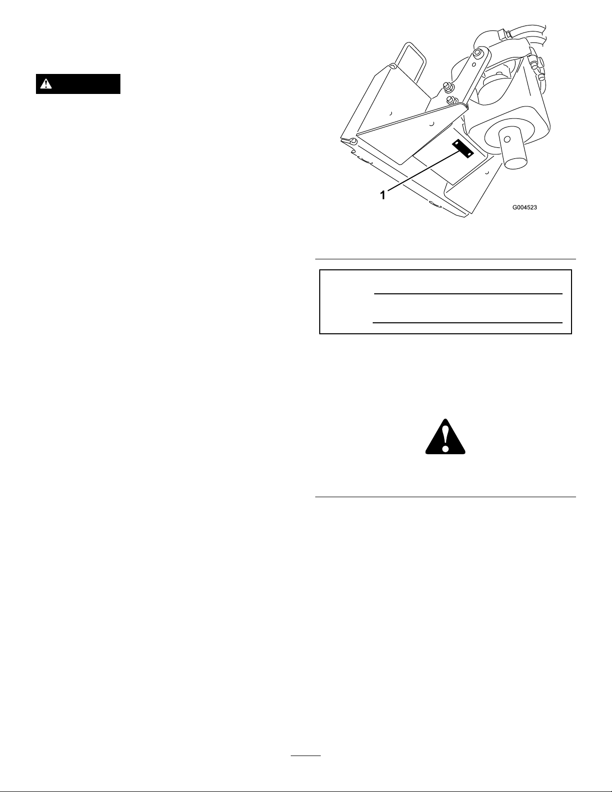
Figure1
1.Modelandserialnumberlocation
ModelNo.
SerialNo.
Readthisinformationcarefullytolearnhowtooperate
andmaintainyourproductproperlyandtoavoidinjury
andproductdamage.Youareresponsibleforoperating
theproductproperlyandsafely .
YoumaycontactTorodirectlyatwww.Toro.comfor
productandaccessoryinformation,helpndinga
dealer,ortoregisteryourproduct.
Wheneveryouneedservice,genuineToroparts,or
additionalinformation,contactanAuthorizedService
DealerorToroCustomerServiceandhavethemodel
andserialnumbersofyourproductready.
Figure1
identiesthelocationofthemodelandserialnumbers
ontheproduct.Onaugersandextensions,themodel
andserialnumberplateislocatedontheupperportion
oftheshaft.Writethenumbersinthespaceprovided.
Thismanualidentiespotentialhazardsandhas
safetymessagesidentiedbythesafetyalertsymbol
(Figure2),whichsignalsahazardthatmaycauseserious
injuryordeathifyoudonotfollowtherecommended
precautions.
Figure2
1.Safetyalertsymbol
Thismanualuses2otherwordstohighlightinformation.
Importantcallsattentiontospecialmechanical
informationandNoteemphasizesgeneralinformation
worthyofspecialattention.
Contents
Introduction.................................................................2
Safety...........................................................................3
StabilityRatings....................................................4
SafetyandInstructionalDecals.............................5
ProductOverview........................................................5
Specications.......................................................5
Operation.....................................................................6
InstallinganAuger...............................................6
DiggingaHole.....................................................7
©2010—TheToro®Company
8111LyndaleAvenueSouth
Bloomington,MN55420
Contactusatwww.T oro.com.
2
PrintedintheUSA.
AllRightsReserved
Page 3

RemovinganAuger..............................................8
Maintenance.................................................................9
RecommendedMaintenanceSchedule(s)..................9
GreasingtheCradleArmPivotPoints...................9
ChangingPlanetaryGearCaseOil........................9
Storage.......................................................................10
Troubleshooting.........................................................11
Safety
Improperuseormaintenancebytheoperatoror
ownercanresultininjury.Toreducethepotential
forinjury,complywiththesesafetyinstructionsand
thoseinthetractionunit
payattentiontothesafetyalertsymbol,which
means
safetyinstruction.Failuretocomplywiththe
instructionmayresultinpersonalinjuryordeath.
Caution
,
W ar ning
DANGER
Contactwithamovingaugercancause
entanglement,severewounds,and/ordeath.
Keepallothersatleast10feetawayfromtheauger
duringoperation.Also,donotreplacethesupplied
boltwhichsecurestheaugertothedriveheadwith
alongerboltasthismayincreasethechancefor
entanglement.
Operator’ s Man ual
,or
Danger
—personal
.Always
DANGER
Theremaybeburiedpower,gas,and/ortelephone
linesintheworkarea.Shockorexplosionmay
occurifyoudigintothem.
Havethepropertyorworkareamarkedforburied
linesanddonotdiginmarkedareas.Contactyour
localmarkingserviceorutilitycompanytohavethe
propertymarked(forexample,intheUnitedStates,
call811forthenationwidemarkingservice).
WARNING
Whentheengineisoff,attachmentsintheraised
positioncangraduallylower.Someonenearbymay
bepinnedorinjuredbytheattachmentasitlowers.
Alwayslowertheattachmentlifteachtimeyoushut
offthetractionunit.
WARNING
Whengoingupordownhill,themachinecould
overturniftheheavyendistowardthedownhill
side.Someonemaybepinnedorseriouslyinjured
bythemachineifitoverturns.
Operateupanddownslopeswiththeheavyend
ofthemachineuphill.Anattachedaugerbitwill
makethefrontendheavy.
3
Page 4
WARNING
Lightningcancausesevereinjuryordeath.If
lightningisseenorthunderisheardinthearea,do
notoperatethemachine;seekshelter.
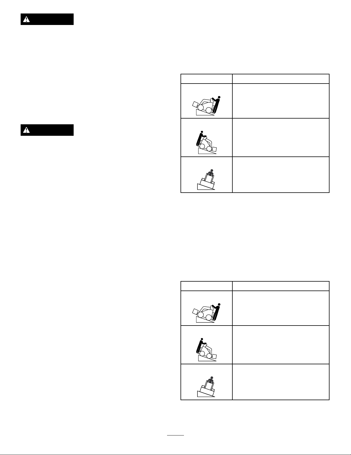
StabilityRatings
Todeterminethedegreeofslopeyoucantraversewith
theaugerinstalledonatractionunit,ndthestability
ratingforthehillpositionyouwanttotravelinthe
appropriatetablebelow ,thenndthedegreeofslope
forthesameratingandhillpositionintheStabilityData
sectionofthetractionunitOperator’sManual.
WARNING
Stabilitywitha12to30inchAuger
Important:Ifyouhaveatractionunitotherthan
aTXcompactutilityloader,usethecounterweight
onthetractionunitwhenusingtheaugerdrive
headwithalargeaugerinstalled.Failuretouse
thecounterweightwillcausethetractionunitto
becomeunstable.
OrientationStabilityRating
FrontUphill
D
RearUphill
Exceedingthemaximumrecommendedslope
cancausethetractionunittotip,crushingyouor
bystanders.
Donotdrivethetractionunitonaslopesteeper
thanthemaximumrecommendedslope,as
determinedinthefollowingtablesandthetraction
Operator’ s Man ual
unit
.
D
SideUphill
C
StabilityWithoutanAugerorwithan
AugerSmallerthan12inches
Important:Ifyouhaveatractionunitother
thanaTXcompactutilityloader,donotusethe
counterweightonthetractionunitwhenusing
theaugerdriveheadwithoutanaugerorwith
anaugersmallerthan12inches.Ifyouusethe
counterweight,thetractionunitwillbelessstable
inthefrontandsideuphillpositions.
OrientationStabilityRating
FrontUphill
D
RearUphill
C
SideUphill
B
4
Page 5

SafetyandInstructional
ProductOverview
Decals
Safetydecalsandinstructionsareeasily
visibletotheoperatorandarelocated
nearanyareaofpotentialdanger.
Replaceanydecalthatisdamagedor
lost.
Figure3
1.Hoseguide
2.Mountingplate5.Drivehead
3.Motor
4.Cradlearm
6.Driveshaft
105-0326
1.Warning—readtheOperator’sManual.
2.Entanglementhazard,auger—keepbystandersasafe
distancefromtheauger.
3.Explosionand/orelectricshockhazard—donotdiginareas
withburiedgasorpowerlines.
Specications
Note:Specicationsanddesignaresubjecttochange
withoutnotice.
Model22805
Width
Length
Height
Weight
Model22806
Width
Length
Height
Weight
24.3inches(62cm)
15.8inches(40cm)
23.3inches(59cm)
182lb(83Kg)
24.3inches(62cm)
16.5inches(42cm)
23.4inches(59cm)
196lb(89Kg)
5
Page 6

Operation
RefertoyourtractionunitOperator’sManualformore
informationoninstallingandremovingattachments
onyourtractionunit.
Note:Alwaysusethetractionunittoliftandmovethe
attachment.Tomoveanaugerwithoutthedrivehead,
slingastrapovereachendoftheaugerandhoistitto
thedesiredlocation.
InstallinganAuger
WARNING
Theaugerheadswingsfreelyinthecradlearms.
Yourhandsorngerscouldgetpinchedand
severelyinjuredoramputatediftheyarecaught
betweenthecradlearmsandtheswingingdrive
head.
Lightlysecuretheboltwithaangenut(1/2inch)
(Figure5).
Keepyourhandsandngersawayfromthecradle
arms.
1.Ifyouareinstallinganaugeronmodel22806drive
head,positionthedriveheadvertically,slideabolt
(1/2x2-1/2inches)intotheholesinthefront
cradlearms,andsecureitlightlywithaangenut
(1/2inch)(
1.Drivehead(frontview)
2.Bolt
Figure4).
Figure4
3.Frontcradlearm
2.Raisetheloaderarmssothedriveheadclearsthe
ground.
Figure5
1.Drivehead
2.Cradlearm
3.Boltandangenut
5.Ifusinganextensionwiththeauger,insertthe
endoftheextensionintotheendoftheaugerand
securetheaugertotheextensionwithabolt(7/8x
4-1/2inch)andnut(7/8inch)(
Figure6
1.Extension
2.Augershaft4.Nut,7/8inch
3.Bolt,7/8x4-1/2inch
Figure6).
6.Starttheengine.
7.Maneuverthedriveshaftintotheendoftheauger
shaftorextension(ifapplicable)(Figure7).
3.Stoptheengine.
4.Manuallyrotatetheaugerdriveheadup,until
youcanslideabolt(1/2x2-1/2inches)intothe
holeinthecradlearm,securingthedrivehead.
6
Page 7

Figure7
1.Drivehead
2.Augershaft
8.Stoptheengine.
9.Securetheaugertothedriveheadwithabolt(7/8x
4-1/2inch)andnut(7/8inch)(Figure8).
DiggingaHole
DANGER
Theremaybeburiedpower,gas,and/ortelephone
linesintheworkarea.Shockorexplosionmay
occurifyoudigintothem.
Havethepropertyorworkareamarkedforburied
linesanddonotdiginmarkedareas.Contactyour
localmarkingserviceorutilitycompanytohave
thepropertymarked(forexample,intheUnited
States,call811forthenationwidemarkingservice).
Important:Beforedigging,ensurethatthe
groundisfreeofanytrashordebris.
Important:Donotusetheaugerunlesstheauger
pointandteethareintactandingoodcondition.
1.Lowertheaugertothesoilatthesiteofthe
proposedhole.
Figure8
1.Bolt,7/8x4-1/2inches3.Bolt(s)andnut(s)
2.Nut,7/8inch
10.Removetheboltsandnutsfromthecradlearms
thatwereinstalledinsteps1(ifapplicable)and4
(Figure8).
11.Starttheengine.
12.Raisetheaugerfreeoftheground(Figure9).
2.MovethethrottlelevertotheFastposition.
3.Ifyourtractionunithasaspeedselectorlever,move
ittotheSlowposition.
4.Ifyourtractionunithasaowdividercontrol,
moveittothe10:00o’clockposition.
5.Pulltheauxiliaryhydraulicslevertotheoperator
griporreferencebartobegindigging.
6.Lowertheaugerslowlyasthesoilisloosened.As
youdigdeeper,movethetractionunitbackward
orforwardasrequiredtokeeptheaugervertical
Figure10).
(
Figure10
Figure9
13.Whentheaugerisvertical,tilttheattachment
platerearward,untilthedriveheadcontactsthe
attachmentplatetostabilizetheaugerandkeepit
fromswingingfreely(Figure9).
7.Whentheaugerbecomesfullofsoil,disengagethe
augerdriveandlifttheaugerfromthehole.Engage
theaugerdrivetospinoffthesoil,thenresume
digging.
Note:Switchingtheauxiliaryhydraulicslever
rapidlyfromforwardtoreversewillhelptoshake
offthesoil.
7
Page 8

DANGER
Ifyouareusingmodel22806,excessivedownward
forcemaycausethebittowobbleuncontrollably
whichcouldtipthetractionunit.Y ouorbystanders
couldbepinedorseriouslyinjured.
Whenusingmodel22806,donotuseexcessive
downwardpressureonthebit.Allowthebittopull
itselfintothesoil.
RemovinganAuger
1.Raisetheloaderarmssotheaugercomesoutof
thehole.
Note:Ifyouhavea24inchextensioninstalled
betweenthedriveheadandtheauger,itmaybe
necessarytoraisetheaugerashighaspossibleand
thenmovethetractionunitbackwardtopullthe
augertherestofthewayoutofthehole.
2.Settheaugerdowninitsstoragelocation.
3.Whileloweringthearms,driveslowlybackwards
untiltheaugerishorizontal.
4.Stoptheengine.
5.Removetheboltandnutsecuringthedriveheadto
theaugerorextension.
6.Starttheengineandbackthetractionunitaway
fromtheauger.
7.Ifyouusedanextension,removetheboltandnut
securingitandpullitoffoftheauger.
8
Page 9

Maintenance
RecommendedMaintenanceSchedule(s)
MaintenanceService
Interval
Aftertherst50hours
Beforeeachuseordaily
Every1,000hours
Beforestorage
MaintenanceProcedure
•Changetheplanetarygearcaseoil.
•Greasethecradlearmpivotpoints.(Greaseallttingsimmediatelyafterevery
washing.)
•Checktheaugerteethandreplacethemiftheyaredamagedorworn.
•Changetheplanetarygearcaseoil.
•Checktheaugerteethandreplacethemiftheyaredamagedorworn.
•Paintchippedsurfaces.
CAUTION
Ifyouleavethekeyintheignitionswitch,someonecouldstarttheengine.Accidentalstartingofthe
enginecouldseriouslyinjureyouorotherbystanders.
Removethekeyfromtheignitionswitchbeforeyoudoanymaintenance.
GreasingtheCradleArmPivot
Points
ServiceInterval:Beforeeachuseordaily(Grease
allttingsimmediatelyafterevery
washing.)
GreaseType:General-purposegrease
1.Stoptheengineandremovethekey.
2.Cleanthegreasettingswitharag.
3.Connectagreaseguntoeachtting.
4.Pumpgreaseintothettingsuntilgreasebeginsto
oozeoutofthebearings.
5.Wipeupanyexcessgrease.
ChangingPlanetaryGearCase
Oil
ServiceInterval:Aftertherst50hours
Every1,000hours
Theplanetarygearcaserequires0.85pintsofamild,
extremepressurelubricant,ratedAPI-GL-5,number
80or90.
1.Supportthedriveheadoveranoilpan(Figure11).
Figure11
1.Planetarygearcase3.Motor
2.Bolts
2.Removethe4boltssecuringthemotorandremove
themotor,allowingalloftheoiltodrainintothepan.
3.Whentheoiliscompletelydrained,turnthedrive
headsothattheopeningisfacingtheup.
4.Add0.85pintsofamild,extremepressurelubricant,
ratedAPI-GL-5,number80or90.
5.Replacethemotorandsecureitwiththefourbolts
removedpreviously.Torquetheboltsto105ft-lb
(142N-m)
9
Page 10

Storage
1.Beforelongtermstorage,washtheattachmentwith
milddetergentandwatertoremovedirtandgrime.
2.Checkandtightenallbolts,nuts,andscrews.Repair
orreplaceanydamagedorwornpart.
3.Ensurethatallhydrauliccouplersareconnected
togethertopreventcontaminationofthehydraulic
system.
4.Paintallscratchedorbaremetalsurfaces.Paintis
availablefromyourAuthorizedServiceDealer.
5.Storetheattachmentinaclean,drygarageorstorage
area.Coverittoprotectitandkeepitclean.
10
Page 11

Troubleshooting
Thedriveheaddoesnotoperate.
Problem
1.Hydrauliccouplernotcompletely
connected
2.Defectivehydrauliccoupler2.Checkcouplersandreplaceanythat
3.Anobstructioninahydraulichose3.Findandremovetheobstruction.
4.Kinkedhydraulichose4.Replacethekinkedhose
5.Contaminationinthegearbox5.Refertoyourauthorizedservicedealer.
PossibleCauseCorrectiveAction
1.Checkandtightenallcouplers.
aredefective.
11
Page 12

ToroCompactUtilityEquipmentWarranty
AOne-YearLimitedWarranty
CUEProducts
ConditionsandProductsCovered
TheT oro®Companyanditsafliate,T oroWarrantyCompany,pursuant
toanagreementbetweenthem,jointlywarrantyourToroCompactUtility
Equipment(“Product”)tobefreefromdefectsinmaterialsorworkmanship.
Thefollowingtimeperiodsapplyfromthedateofpurchase:
ProductsWarrantyPeriod
Loaders,TrenchersandAttachments1yearor1000operating
hours,whicheveroccursrst
KohlerEngines3years
AllotherEngines2years
Whereawarrantableconditionexists,wewillrepairtheProductatnocost
toyouincludingdiagnosis,labor,andparts.
InstructionsforObtainingWarrantyService
IfyouthinkthatyourT oroProductcontainsadefectinmaterialsor
workmanship,followthisprocedure:
1.ContactanyAuthorizedT oroCompactUtilityEquipment(CUE)
ServiceDealertoarrangeserviceattheirdealership.Tolocatea
dealerconvenienttoyou,accessourwebsiteatwww.Toro.com.
YoumayalsocallourToroCustomerCareDepartmenttollfree
at888-865-5676(U.S.customers)or888-865-5691(Canadian
customers).
2.Bringtheproductandyourproofofpurchase(salesreceipt)tothe
ServiceDealer.
3.IfforanyreasonyouaredissatisedwiththeServiceDealer’s
analysisorwiththeassistanceprovided,contactusat:
LCBCustomerCareDepartment
ToroWarrantyCompany
811 1L yndaleAvenueSouth
Bloomington,MN55420-1 196
TollFree:888-865-5676(U.S.customers)
TollFree:888-865-5691(Canadacustomers)
OwnerResponsibilities
YoumustmaintainyourT oroProductbyfollowingthemaintenance
proceduresdescribedintheOperator’sManual.Suchroutine
maintenance,whetherperformedbyadealerorbyyou,isatyourexpense.
Partsscheduledforreplacementasrequiredmaintenance(“Maintenance
Parts”),arewarrantedfortheperiodoftimeuptothescheduled
replacementtimeforthatpart.Failuretoperformrequiredmaintenance
andadjustmentscanbegroundsfordisallowingawarrantyclaim.
ItemsandConditionsNotCovered
Notallproductfailuresormalfunctionsthatoccurduringthewarranty
periodaredefectsinmaterialsorworkmanship.Thisexpresswarranty
doesnotcoverthefollowing:
•Productfailureswhichresultfromtheuseofnon-T ororeplacement
parts,orfrominstallationanduseofadd-on,modied,orunapproved
accessories
•Productfailureswhichresultfromfailuretoperformrequired
maintenanceand/oradjustments
•ProductfailureswhichresultfromoperatingtheProductinan
abusive,negligentorrecklessmanner
•Partssubjecttoconsumptionthroughuseunlessfoundtobe
defective.Examplesofpartswhichareconsumed,orusedup,during
normalProductoperationinclude,butarenotlimitedto,diggingteeth,
tines,sparkplugs,tires,tracks,lters,chains,etc.
•Failurescausedbyoutsideinuence.Itemsconsideredtobeoutside
inuenceinclude,butarenotlimitedto,weather ,storagepractices,
contamination,useofunapprovedcoolants,lubricants,additives,or
chemicals,etc.
•Normal“wearandtear”items.Normal“wearandtear”includes,butis
notlimitedto,wornpaintedsurfaces,scratcheddecalsorwindows,
etc.
•Anycomponentcoveredbyaseparatemanufacturer’swarranty
•Pickupanddeliverycharges
GeneralConditions
RepairbyanAuthorizedT oroCompactUtilityEquipment(CUE)Service
Dealerisyoursoleremedyunderthiswarranty.
NeitherTheToro®CompanynorT oroWarrantyCompanyisliable
forindirect,incidentalorconsequentialdamagesinconnectionwith
theuseoftheToroProductscoveredbythiswarranty ,including
anycostorexpenseofprovidingsubstituteequipmentorservice
duringreasonableperiodsofmalfunctionornon-usepending
completionofrepairsunderthiswarranty .Allimpliedwarranties
ofmerchantabilityandtnessforusearelimitedtotheduration
ofthisexpresswarranty .Somestatesdonotallowexclusionsof
incidentalorconsequentialdamages,orlimitationsonhowlong
animpliedwarrantylasts,sotheaboveexclusionsandlimitations
maynotapplytoyou.
Thiswarrantygivesyouspeciclegalrights,andyoumayalsohaveother
rightswhichvaryfromstatetostate.
ExceptfortheenginewarrantycoverageandtheEmissionswarranty
referencedbelow,ifapplicable,thereisnootherexpresswarranty.The
EmissionsControlSystemonyourProductmaybecoveredbyaseparate
warrantymeetingrequirementsestablishedbytheU.S.Environmental
ProtectionAgency(EPA)ortheCaliforniaAirResourcesBoard(CARB).
ThehourlimitationssetforthabovedonotapplytotheEmissions
ControlSystemWarranty.RefertotheCaliforniaEmissionControl
WarrantyStatementsuppliedwithyourProductorcontainedintheengine
manufacturer’sdocumentationfordetails.
CountriesOtherthantheUnitedStatesorCanada
CustomerswhohavepurchasedT oroproductsexportedfromtheUnitedStatesorCanadashouldcontacttheirT oroDistributor(Dealer)toobtain
guaranteepoliciesforyourcountry ,province,orstate.IfforanyreasonyouaredissatisedwithyourDistributor’sserviceorhavedifcultyobtaining
guaranteeinformation,contacttheToroimporter .Ifallotherremediesfail,youmaycontactusatT oroWarrantyCompany.
374-0261RevA
 Loading...