

Page 1

Form No. 3353-820 Rev A
Auger and Universal Swivel Auger
Drive Head
for Compact Utility Loaders
Model No. 22802—Serial No. 220000001 & Up
Model No. 22803—Serial No. 220000001 & Up
Operator’s Manual
Original Instructions (EN)Register your product at www.Toro.com
Page 2
Contents
Introduction 2. . . . . . . . . . . . . . . . . . . . . . . . . . . . . . . . .
Safety 2. . . . . . . . . . . . . . . . . . . . . . . . . . . . . . . . . . . . . .
Safety and Instruction Decals 3. . . . . . . . . . . . . . . . .
Specifications 3. . . . . . . . . . . . . . . . . . . . . . . . . . . . . . . .
Stability Ratings 4. . . . . . . . . . . . . . . . . . . . . . . . . . .
Setup 4. . . . . . . . . . . . . . . . . . . . . . . . . . . . . . . . . . . . . .
Loose/Separate/Optional Parts 5. . . . . . . . . . . . . . . .
Installing an Auger onto the Drive Head 5. . . . . . . .
Removing an Auger/Extension from the Drive
Head 6. . . . . . . . . . . . . . . . . . . . . . . . . . . . . . . . . .
Operation 6. . . . . . . . . . . . . . . . . . . . . . . . . . . . . . . . . . .
Digging a Hole 6. . . . . . . . . . . . . . . . . . . . . . . . . . . .
Maintenance 7. . . . . . . . . . . . . . . . . . . . . . . . . . . . . . . . .
Recommended Maintenance Schedule 7. . . . . . . . .
Greasing the Cradle Arm Pivot Points 7. . . . . . . . . .
Checking Planetary Gear Case Oil 7. . . . . . . . . . . . .
Changing Planetary Gear Case Oil 8. . . . . . . . . . . .
Storage 8. . . . . . . . . . . . . . . . . . . . . . . . . . . . . . . . . .
Troubleshooting 8. . . . . . . . . . . . . . . . . . . . . . . . . . . . . .
Page
Danger signals an extreme hazard that will cause serious
injury or death if you do not follow the recommended
precautions.
Warning signals a hazard that may cause serious injury or
death if you do not follow the recommended precautions.
Caution signals a hazard that may cause minor or moderate
injury if you do not follow the recommended precautions.
This manual uses two other words to highlight information.
Important calls attention to special mechanical
information and Note: emphasizes general information
worthy of special attention.
Safety
Improper use or maintenance by the operator or owner
can result in injury. To reduce the potential for injury,
comply with these safety instructions and those in the
traction unit operator’s manual. Always pay attention
to the safety alert
WARNING, or DANGER—“personal safety
instruction.” Failure to comply with the instruction may
result in personal injury or death.
symbol, which means CAUTION,
Danger
Introduction
Read this manual carefully to learn how to operate and
maintain your product properly. The information in this
manual can help you and others avoid injury and product
damage. Although Toro designs and produces safe
products, you are responsible for operating the product
properly and safely.
Whenever you need service, genuine Toro parts, or
additional information, contact an Authorized Service
Dealer or Toro Customer Service and have the model and
serial numbers of your product ready. You will find the
model and serial number on a plate located on the auger
drive head. On augers and extensions, the model and serial
number plate is located on the upper portion of the shaft.
Write the product model and serial numbers in the space
below:
Model No.
Serial No.
This manual identifies potential hazards and has special
safety messages that help you and others avoid personal
injury and even death. Danger, Warning, and Caution are
signal words used to identify the level of hazard. However,
regardless of the hazard, be extremely careful.
Contact with a moving auger can cause
entanglement, severe wounds, and/or death.
Keep all others at least 10 feet away from the
auger during operation. Also, do not replace the
supplied bolt which secures the auger to the drive
head with a longer bolt as this may increase the
chance for entanglement.
Danger
If there are buried power, gas, or telephone lines in
the work area, you may dig into them causing
shock or explosion.
Have the property or work area marked for buried
lines and do not dig in marked areas.
Warning
When the engine is off, attachments in the raised
position can gradually lower, possibly pinning or
injuring someone.
Always lower the attachment lift each time you
shut off the traction unit.
W 2005 by The Toro Company
8111 Lyndale Avenue South
Bloomington, MN 55420-1196
Contact us at www.Toro.com
All Rights Reserved
2
Printed in the USA
Page 3
Warning
Specifications
When going up or down hill, the machine could
overturn if the heavy end is toward the downhill
side, possibly pinning or seriously injuring you or
bystanders.
Operate up and down slopes with the heavy end of
the machine uphill. An attached auger bit will
make the front end heavy.
Safety and Instruction Decals
Safety decals and instructions are easily
visible to the operator and are located near
any area of potential danger. Replace any
decal that is damaged or lost.
Note: Specifications and design are subject to change
without notice.
Model 22802
Width 24 inches (61 cm)
Length 16-1/2 inches (42 cm)
Height 22 inches (56 cm)
Weight (without auger) 215 lb (98 Kg)
Maximum auger dia. 30 inches (76 cm)
Motor displacement 11.9 in3/rev (29 cm3/rev)
Motor rated pressure 3000 PSI Continuous
(211 Kg/cm
Motor flow range 0–20 GPM (38–76 LPM)
Drive ratio 3.75:1
Output shaft diameter 2-9/16 inches (6.5 cm)
2
)
Model 22803
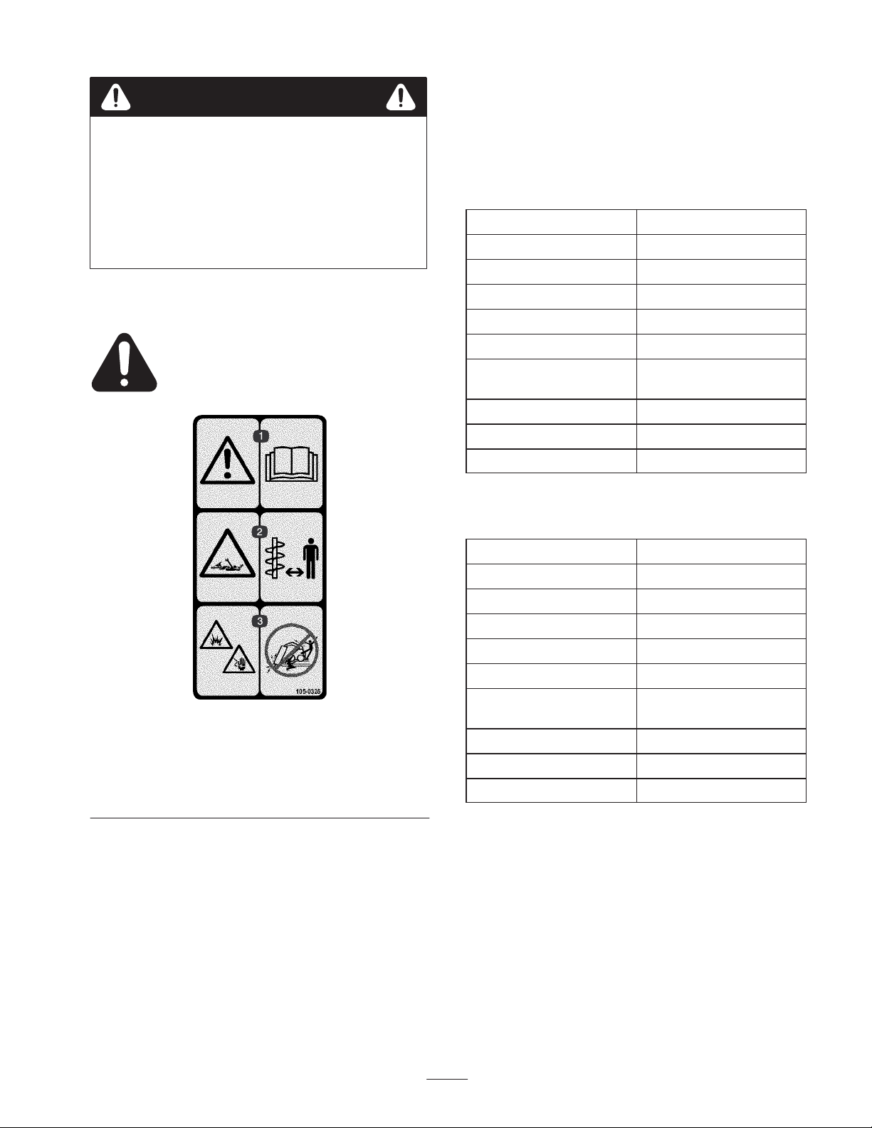
105-0326
1. Warning—read the Operator’s Manual.
2. Entanglement hazard, shaft—keep bystanders a safe distance
from the auger.
3. Explosion and electric shock hazards—do not dig in areas with
buried gas or electrical lines.
Width 24 inches (61 cm)
Length 19.3 inches (49 cm)
Height 22 inches (56 cm)
Weight (without auger) 243 lb (111 Kg)
Maximum auger dia. 15 inches (38 cm)
Motor displacement 8.0 in3/rev (130 cm3/rev)
Motor rated pressure 3000 PSI Continuous
(211 Kg/cm
Motor flow range 0–20 GPM (38–76 LPM)
Drive ratio 3.75:1
Output shaft diameter 2-9/16 inches (6.5 cm)
2
)
3
Page 4

Stability Ratings
To determine the degree of slope you can traverse with the auger installed on a traction unit, find the stability rating for the
hill position you want to travel in the appropriate table below, then find the degree of slope for the same rating and hill
position in the Stability Data section of the traction unit operator’s manual.
Warning
Exceeding the maximum slope can cause the traction unit to tip, possibly pinning or seriously
injuring you or bystanders.
Do not drive the traction unit on a slope steeper than the maximum slope.
Stability With a 12 to 30 inch Auger
Orientation
Front Uphill
Stability Rating
D
Rear Uphill
D
Side Uphill
C
Important If you have a traction unit other than a TX
compact utility loader, use the counterweight on the
traction unit when using the auger drive head with a large
auger installed. Failure to use the counterweight will cause
the traction unit to become unstable.
Stability Without an Auger or with an
Auger Smaller than 12 inches
Orientation
Front Uphill
Stability Rating
D
Rear Uphill
C
Side Uphill
B
Note: If you have a traction unit other than a TX compact
utility loader, do not use the counterweight on the traction
unit when using the auger drive head without an auger or
with an auger smaller than 12 inches. If you use the
counterweight, the traction unit will be less stable in the
front and side uphill positions.
Setup
Refer to your traction unit Operator’s Manual for more information on installing and removing the drive head on your
traction unit.
Note: Always use the traction unit to lift and move the drive head. To move an auger without the drive head, sling a strap
over each end of the auger and hoist it to the desired location.
4
Page 5

Loose/Separate/Optional Parts
Description Qty. Use
Auger (any size, sold separately)
Bolt, 1/2 x 2-3/4 inch (model 22802)
Flange nut, 1/2 inch (model 22802)
Bolt, 1/2 x 2-3/4 inch (model 22803)
Flange nut, 1/2 inch (model 22803)
Bolt, 7/8 x 4-1/2 inch
Nut, 7/8 inch
Auger extension, bolt, and nut (optional
product, sold separately)
Counterweight (sold separately) 1
Installing an Auger onto the
Drive Head
Warning
The auger head swings freely in the cradle arms.
Your hands or fingers could get pinched and
severely injured or amputated if they are caught
between the cradle arms and the swinging drive
head.
1
1
1
2
Install auger on drive head
2
1
1
1 Install between drive head and auger
Required for use with large diameter augers
(not for use on TX compact utility loaders)
3. Stop the engine.
4. Manually rotate the auger drive head up, until you can
slide a bolt (1/2 x 2-3/4 inch) into the hole in the cradle
arm, securing the drive head. Lightly secure the bolt
with a flange nut (1/2 inch) (Fig. 2).
3
1
2
Keep your hands and fingers away from the cradle
arms.
1. If you are installing an auger on model 22803 drive
head, position the drive head vertically, slide a bolt
(1/2 x 2-3/4 inch) into the holes in the front cradle arms,
and secure it lightly with a flange nut (1/2 inch)
(Fig. 2).
2
3
1
m–5989
Figure 1
1. Drive head (front view)
2. Bolt
3. Front cradle arm
2. Raise the loader arms so the drive head clears the
ground.
m–5984
Figure 2
1. Drive head
2. Cradle arm
3. Bolt and flange nut
5. If using an extension with the auger, insert the end of
the extension into the end of the auger and secure the
auger to the extension with a bolt (7/8 x 4-1/2 inch) and
nut (7/8 inch) (Fig. 3).
3
1
4
2
m–3971
Figure 3
1. Extension
2. Auger shaft
3. Bolt, 7/8 x 4-1/2 inch
4. Nut, 7/8 inch
6. Start the engine.
5
Page 6

7. Maneuver the drive shaft into the end of the auger shaft
or extension (if applicable) (Fig. 4).
1
1. Drive head 2. Auger shaft
8. Stop the engine.
9. Secure the auger to the drive head with a bolt (7/8 x
4-1/2 inch) and nut (7/8 inch) (Fig. 5).
10. Remove the bolts and nuts from the cradle arms that
were installed in steps 1 (if applicable) and 4 (Fig. 5).
2
Figure 4
m–3945
Removing an Auger/Extension
from the Drive Head
1. Raise the loader arms so the auger comes out of the
hole.
Note: If you have a 24 inch extension installed between the
drive head and the auger, it may be necessary to raise the
auger as high as possible and then move the traction unit
backward to pull the auger the rest of the way out of the
hole.
2. Set the auger down in its storage location.
3. While lowering the arms, drive slowly backwards until
the auger is horizontal.
4. Stop the engine.
5. Remove the bolt and nut securing the drive head to the
auger or extension.
3
1
m–5986
Figure 5
1. Bolt, 7/8 x 4-1/2 inch
2. Nut, 7/8 inch
11. Start the engine.
12. Raise the auger free of the ground (Fig. 6).
13. When the auger is vertical, tilt the attachment plate
rearward, until the drive head contacts the attachment
plate to stabilize the auger and keep it from swinging
freely (Fig. 6).
3. Bolt(s) and nut(s)
2
6. Start the engine and back the traction unit away from
the auger.
7. If an extension was used, remove the bolt and nut
securing it and pull it off of the auger.
Operation
Digging a Hole
Danger
If there are buried power, gas, or telephone lines in
the work area, you may dig into them causing
shock or explosion.
Have the property or work area marked for buried
lines and do not dig in marked areas.
Important Before digging, ensure that the ground is
free of any trash or debris.
Important Do not use the auger unless the auger point
and teeth are intact and in good condition.
Figure 6
m–3948
1. Lower the auger to the soil at the site of the proposed
hole.
2. Move the throttle lever to the Fast position.
3. If your traction unit has a speed selector lever, move it
to the Slow position.
4. If your traction unit has a flow divider control, move it
to the 10:00 o’clock position.
6
Page 7

5. Pull the auxiliary hydraulics lever to the operator grip
or reference bar to begin digging.
6. Lower the auger slowly as the soil is loosened. As you
dig deeper, move the traction unit backward or forward
as required to keep the auger vertical (Fig. 7).
7. When the auger becomes full of soil, disengage the
auger drive and lift the auger from the hole. Engage the
auger drive to spin off the soil, then resume digging.
Note: Switching the auxiliary hydraulics lever rapidly from
forward to reverse will help to shake off the soil.
Danger
If you are using model 22803, excessive downward
force may cause the bit to wobble uncontrollably
which could tip the traction unit. You or
bystanders could be pined or seriously injured.
m–3950
m–3951
Figure 7
When using model 22803, do not use excessive
downward pressure on the bit. Allow the bit to pull
itself into the soil.
Maintenance
Recommended Maintenance Schedule
Maintenance Service
Interval
Each Use
25 hours • Check the planetary gear case oil
1000 hours • Change the planetary gear case oil.
Storage
Maintenance Procedure
• Inspect the auger teeth and replace them if they are damaged or worn.
• Grease the pivot points on the cradle arms.
• Inspect the auger teeth and replace them if they are damaged or worn.
• Paint chipped surfaces
Caution
If you leave the key in the ignition switch, someone could start the engine, seriously injuring you
or bystanders.
Remove the key from the ignition switch before performing any maintenance.
Greasing the Cradle Arm Pivot
Points
Grease the fittings on the pivot points of the cradle arms
before each use. Also, grease all fittings immediately after
every washing.
Grease Type: General-purpose grease
1. Stop the engine and remove the key.
2. Clean the grease fittings with a rag.
3. Connect a grease gun to each fitting.
4. Pump grease into the fittings until grease begins to ooze
out of the bearings.
5. Wipe up any excess grease.
Checking Planetary Gear Case
Oil
Check the oil level in the planetary gear case every
25 hours and top off the oil if necessary.
7
Page 8

1. Place the auger drive head on the ground so that the
drive shaft is parallel with the ground.
2. Rotate the drive head so that one of the oil drain plugs
is located on top (Fig. 8).
3. Remove the upper oil drain plug (Fig. 8)
4. Rotate the auger drive head so that the drain opening is
at the 2 o’clock position (Fig 8). Oil should just begin to
come out of the opening.
1
1
Figure 8
1. Drain plug
m–5987
Changing Planetary Gear Case
Oil
Change the oil after the first 50 hours of operation and
every 1000 hours thereafter. The planetary gear case
requires 1.69 pints of a mild, extreme pressure lubricant,
rated API–GL–5, number 80 or 90.
1. Support the drive head over an oil pan so that one of the
oil drain plugs (Fig. 8) is on the bottom of the drive
head, facing the oil pan.
2. Remove the bottom oil drain plug to drain the oil.
3. When the oil is completely drained, turn the drive head
so that the oil drain opening is on the top of the drive
head, facing the up.
4. Add 1.69 pints of a mild, extreme pressure lubricant,
rated API–GL–5, number 80 or 90.
5. Replace the drain plug.
Storage
1. Before long term storage, wash the attachment with
mild detergent and water.
2. Check and tighten all bolts, nuts, and screws. Repair or
replace any damaged or worn part.
5. If no oil comes out of the opening, add oil (a mild,
extreme pressure lubricant API–GL–5, number 80 or
90) until the oil starts to run out when the drain hole is
at the 2 o’clock position.
6. Replace the drain plug.
Troubleshooting
Problem Possible Causes Corrective Action
Drive head does not operate.
1. Hydraulic coupler not
completely connected
2. Defective hydraulic coupler 2. Check couplers and replace
3. An obstruction in a hydraulic
hose
4. Kinked hydraulic hose 4. Replace the kinked hose
5. Contamination in the gearbox 5. Refer to your authorized
3. Ensure that all hydraulic couplers are connected
together to prevent contamination of the hydraulic
system.
4. Paint all scratched or bare metal surfaces. Paint is
available from your Authorized Service Dealer.
5. Store the attachment in a clean, dry garage or storage
area. Cover it to protect it and keep it clean.
1. Check and tighten all couplers.
any that are defective.
3. Find and remove the
obstruction.
service dealer.
8
 Loading...